EP2980333B1 - Baugerüst mit einem gerüstelement - Google Patents
Baugerüst mit einem gerüstelement Download PDFInfo
- Publication number
- EP2980333B1 EP2980333B1 EP15178798.3A EP15178798A EP2980333B1 EP 2980333 B1 EP2980333 B1 EP 2980333B1 EP 15178798 A EP15178798 A EP 15178798A EP 2980333 B1 EP2980333 B1 EP 2980333B1
- Authority
- EP
- European Patent Office
- Prior art keywords
- railing
- gudgeon
- push
- scaffold
- stile
- Prior art date
- Legal status (The legal status is an assumption and is not a legal conclusion. Google has not performed a legal analysis and makes no representation as to the accuracy of the status listed.)
- Active
Links
Images


Classifications
-
- E—FIXED CONSTRUCTIONS
- E04—BUILDING
- E04G—SCAFFOLDING; FORMS; SHUTTERING; BUILDING IMPLEMENTS OR AIDS, OR THEIR USE; HANDLING BUILDING MATERIALS ON THE SITE; REPAIRING, BREAKING-UP OR OTHER WORK ON EXISTING BUILDINGS
- E04G5/00—Component parts or accessories for scaffolds
- E04G5/14—Railings
- E04G5/145—Toe boards therefor
-
- E—FIXED CONSTRUCTIONS
- E04—BUILDING
- E04G—SCAFFOLDING; FORMS; SHUTTERING; BUILDING IMPLEMENTS OR AIDS, OR THEIR USE; HANDLING BUILDING MATERIALS ON THE SITE; REPAIRING, BREAKING-UP OR OTHER WORK ON EXISTING BUILDINGS
- E04G5/00—Component parts or accessories for scaffolds
- E04G5/06—Consoles; Brackets
- E04G5/061—Consoles; Brackets specially adapted for attachment to scaffolds
-
- E—FIXED CONSTRUCTIONS
- E04—BUILDING
- E04G—SCAFFOLDING; FORMS; SHUTTERING; BUILDING IMPLEMENTS OR AIDS, OR THEIR USE; HANDLING BUILDING MATERIALS ON THE SITE; REPAIRING, BREAKING-UP OR OTHER WORK ON EXISTING BUILDINGS
- E04G7/00—Connections between parts of the scaffold
- E04G7/30—Scaffolding bars or members with non-detachably fixed coupling elements
- E04G7/302—Scaffolding bars or members with non-detachably fixed coupling elements for connecting crossing or intersecting bars or members
- E04G7/303—Scaffolding bars or members with non-detachably fixed coupling elements for connecting crossing or intersecting bars or members the added coupling elements are only fixed at one of the bars or members to connect
- E04G7/305—Scaffolding bars or members with non-detachably fixed coupling elements for connecting crossing or intersecting bars or members the added coupling elements are only fixed at one of the bars or members to connect without tying means for connecting the bars or members
-
- E—FIXED CONSTRUCTIONS
- E04—BUILDING
- E04G—SCAFFOLDING; FORMS; SHUTTERING; BUILDING IMPLEMENTS OR AIDS, OR THEIR USE; HANDLING BUILDING MATERIALS ON THE SITE; REPAIRING, BREAKING-UP OR OTHER WORK ON EXISTING BUILDINGS
- E04G7/00—Connections between parts of the scaffold
- E04G7/30—Scaffolding bars or members with non-detachably fixed coupling elements
- E04G7/34—Scaffolding bars or members with non-detachably fixed coupling elements with coupling elements using positive engagement, e.g. hooks or pins
-
- E—FIXED CONSTRUCTIONS
- E04—BUILDING
- E04G—SCAFFOLDING; FORMS; SHUTTERING; BUILDING IMPLEMENTS OR AIDS, OR THEIR USE; HANDLING BUILDING MATERIALS ON THE SITE; REPAIRING, BREAKING-UP OR OTHER WORK ON EXISTING BUILDINGS
- E04G5/00—Component parts or accessories for scaffolds
- E04G5/001—Safety or protective measures against falling down relating to scaffoldings
Definitions
- the present invention relates to a scaffolding according to the preamble of claim 1.
- protective nets or protective grids For scaffolding, there is a general requirement that protective nets or protective grids must be installed in an upper area near the roof of a building, for example, to prevent the workers from falling or objects from falling.
- roof scaffoldings For this purpose, it is known to design such scaffolding in its upper region as so-called roof scaffoldings.
- protective nets can be attached to interconnected vertical beams of scaffolding elements and to substantially horizontally extending railing elements by threading or by Gurtschnellver say.
- the EP 0 268 197 A2 discloses a scaffolding element for a scaffolding according to the preamble of claim 1.
- a horizontal spar of the scaffold element is provided near the vertical spar to the vertical spar substantially parallel and from the horizontal spar upwardly extending Begrenzungselement-Aufsteckdorn.
- a railing element plug-on mandrel extending substantially horizontally beyond the limiting element plug-in mandrel extends in an area above the limiting element plug-on mandrel intended.
- the DE 10 2008 005 813 A1 discloses a scaffolding member having a pin extending upwardly from a horizontal spar which can be positioned engaging an associated aperture in a pad plank to be positioned on the horizontal spar. On a vertical spar can this be secured against lifting securing pin in an area above the plank pile.
- the DE 10 2009 049 276 A1 discloses a scaffolding in which a scaffolding element constructed with a vertical spar and a horizontal spar has a limiting element arbor on the horizontal spar. On the vertical spar a plurality of fastening devices are provided at a distance from the horizontal spar and over the limiting element-arbor, one above the other, to which a network or wooden boards or other plates can be attached.
- a scaffolding according to claim 1 This comprises at least one scaffold element with a substantially vertically oriented vertical spar, a substantially horizontally oriented, extending from the vertical spar away horizontal spar and on the vertical spar over the horizontal spar at least one railing element arbor ,
- a railing element can be coupled by attachment to an arbor with the scaffolding element. Since the at least one railing element-Avemsteckdorn integrated in a scaffold frame element above the horizontal spar of Scaffolding element is located, this horizontal spar can be used, for example, to hold floor elements for the floor covering on a scaffold, a railing element can be positioned on a railing element arbor above or near the floor level and thus also for connection of a protective network to the scaffold in or be set near the covering layer or the bottom elements providing such a covering layer.
- a limiting element Aufsteckdorn is provided on the horizontal spar. This is used to define a limiting element on the scaffolding element.
- a limiting element can be provided, for example, by a so-called drop-side wall, which is positioned near or slightly above the floor elements which provide the covering layer and can prevent lateral falling down of objects positioned on the floor elements.
- a distance of the limiting element Aufsteckdorns to the vertical spar is greater than a maximum projection length of the at least one railing element arbor from the vertical spar.
- a railing element is plugged and on the provided on the horizontal spar boundary element arbor at least one limiting element is plugged such that at least one railing element plugged on a railing railing element blocked by a limiting element against removal from the railing element arbor is.
- At least one railing element arbor extends substantially parallel to the horizontal spar.
- a structurally simple embodiment for connecting a plurality of railing elements to a scaffolding element may provide that a pair of railing element Aufsteckdornen is provided substantially in the same longitudinal extension region of the vertical spar, it being provided that a pair of Gelanderelement-Avemsteckdornen providing Dorn element provided on the vertical spar is.
- a pair of railing element Aufsteckdornen it is possible to use conventional railing elements and to use it already provided openings for mounting on the railing element Aufsteckdorne.
- the railing element arbors of the pair of railing element arbors be mutually and / or horizontal extend substantially parallel and / or are arranged substantially symmetrically with respect to a vertical center plane of the horizontal spar.
- At least one railing element arbor is fixed to the vertical spar by welding, or that at least one railing mandrel arbor on the vertical spar by screwing and / or clamps is fixed.
- the possibility is given to provide one or more railing element Aufsteckdorne also at different height positions of a scaffold element, depending on whether or in which height range attaching one or more Gelanderelement-Avemsteckdorne is required.
- the limiting element- Aufsteckdorn extending from the horizontal spar upwards preferably substantially parallel to the vertical spar.
- the limiting-element plug-on mandrel prefferably arranged essentially centrally with respect to the railing element plug-on mandrels of the pair of railing element plug-on mandrels.
- a railing element arbor element to be attached to a scaffolding element of a scaffolding may comprise a mounting area for releasably securing the railing element arbor element to the vertical spar and at the attachment area at least one railing element arbor.
- a railing element arbor element can be fixed to a conventionally constructed scaffolding element with one or more vertical beams or one or more horizontal beams, so that a high degree of variability in the construction of a scaffold can be achieved.
- the scaffolding according to the invention can furthermore be constructed in such a way that in each case a railing element is plugged onto each railing element arbor of a pair of railing element arbors such that the railing elements extend away from the skeleton element in substantially the opposite direction and / or that on the boundary element Arbor two limiting elements are plugged in such a way that the boundary elements extend substantially in the opposite direction away from the scaffold element.
- the measure b) attaching one railing element to each railing element plug-on spike so that the railing elements are essentially in one another extend opposite direction of the scaffold element comprises.
- the measure c) the attachment of two boundary elements on the boundary element Aufsteckdorn such that the boundary elements extend in substantially opposite direction away from the scaffold element comprises.
- a protective net can be connected to at least one railing element. This can be done, for example, by threading the railing element into meshes of the protective net before carrying out the measure b), and then, when implementing the measure b), the railing element in each case in at least one of its two end regions, preferably at both end regions, each on a railing element-Avemsteckdorn a scaffolding element is attached.
- the connection of the protective net to the railing element can also take place after being attached to one or two railing element plug-on mandrels of one or two framework elements. This binding of a protective net can also be done before or after the attachment of the railing element against peeling blocking limiting element on one or two Begrenzungselement-Avemsteckdorne.
- a railing element-Aufsteckdorn element is fixed to the vertical beam by screwing and / or terminals.
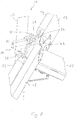
- the Fig. 1 to 7 show a first embodiment of a generally designated 10 scaffolding element.
- the scaffolding element 10 is one in one Scaffolding according to the invention, substantially vertical to be oriented vertical spar 12 and formed in a lower end portion 14 of the vertical beam 12 of the vertical spar 12 approximately orthogonal away, in the scaffolding substantially horizontal to be oriented horizontal spar 16 is formed. Since the vertical spar 12 and the horizontal spar 16 are generally constructed of metal material, the horizontal spar 16 is advantageously fixed by welding to the vertical spar 12.
- the designation refers vertically and horizontally to an orientation of the respective spars in the scaffold according to the invention to be provided in use.
- the statements "above” or “below” mean a relative positioning of various subassemblies or sections thereof in the case of customary incorporation or positioning of a scaffolding element 10 in the scaffolding.
- the lower end region 14 of the vertical spar 12 will in principle be arranged such that it lies downwards in the vertical or vertical direction, while an upper end region 18 of the vertical spar 12 will generally be positioned above, ie above the lower end region 14.
- the coupling elements 20 are provided in different longitudinal extension regions, with which substantially horizontally extending to be positioned railing elements 22 and 24, as well as in Fig. 1 are recognizable, can be coupled.
- the railing elements 22, 24 in their end regions 26, 28 are substantially angled, in particular bent at right angles and have approximately orthogonal to the longitudinal direction of the railing elements 22, 24 extending, advantageously formed from flat coupling portions 30, 32, from above into the Coupling elements 20 can be inserted and locked therein.
- the illustration in Fig. 1 two railings - Elements 22, 24 shows, whose end portions 26, 28 are positioned adjacent to each other.
- each of the two railing elements 22, 24 is constructed such that it has, for example, the end region 26 at one end region and, for example, the end region 28 at the other end region.
- Each railing element can thus be coupled in its two end regions 26, 28 with a framework element 10 or the coupling elements provided there or in the manner described below with its two end regions 26, 28 each with a railing element arbor two horizontally spaced to each other arranged scaffolding elements 10 are coupled.
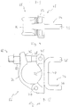
- a essentially U-shaped and formed in the Fig. 4 to 7 more clearly visible mandrel element 34 is provided.
- the mandrel element 34 has two U-legs of the same, essentially parallel to each other extending Gelän - derelement Aufsteckdorne 36, 38 and a connecting them and connected for example by welding to the vertical spar 12 connecting web 40.
- the railing element arbors 36, 38 may, as shown in FIG Fig. 1 may have a substantially square or rectangular cross-section, but, as shown in the 6 and 7 is shown, also have a circular cross-section.
- the positioning of the railing element Aufsteckdorne 36, 38 with respect to the vertical beam 12 and also emanating from this horizontal beam 16 is such that the two substantially in the same longitudinal extension region of the vertical spar and thus at the same distance from the horizontal spar 16 positioned railing mandrels 36, 38th to a vertical center plane M of the horizontal spar 16 or of the entire frame element 10, which in the illustration of Fig. 5 orthogonal to the drawing plane stands, are arranged substantially symmetrically. Both railing element Aufsteckdorne 36, 38 thus also extend substantially symmetrically and parallel to the horizontal spar 16 and have the vertical center plane M at substantially the same distance.
- the horizontal spar 16 is provided at a distance from the vertical spar 12 from the horizontal spar 16 upwards, ie in the direction of the upper end portion 18 of the vertical spar 12 extending limiting element embarksteckdorn 42.
- This may for example be fixed by welding to the horizontal spar 16 and may extend substantially parallel to the vertical spar and preferably over the railing element Aufsteckdorne 36, 38 addition.
- the limiting element Aufsteckdorn 42 is preferably centrally, ie in the region of the vertical center plane M on the horizontal spar 16 and thus also positioned centrally between the two railing element Aufsteckdornen 36, 38.
- the distance of the limiting member Aufsteckdorns 42 to the vertical spar 16 is greater than the maximum extension length of the railing element Aufsteckdorne 36, 38 from the vertical spar 12, so that between the ends 44, 46 of the railing element Aufsteckdorne 36, 38 and the limiting element Aufsteckdorn 42 in the longitudinal direction of the horizontal spar 16 is a distance.
- the angled bent end portions 26, 28 of the railing elements 22, 24 are for receiving the railing element Aufsteckdorne 36, 38 mandrel openings 60, 62 are provided. These are positioned so that when the railing element Aufsteckdornen 36, 38 inserted into these mandrel openings 60, 62, the coupling portions 30, 32 of the connected to the frame member 10 railing elements 22, 24 are positioned substantially overlapping each other and extending in the direction of the vertical spar 12.
- the two coupling sections 30, 32 thus lie with respect to each other in such a way as they would also be in the coupling state with a coupling element 20 provided on the vertical spar 12, but in a positioning in which they extend upwards, ie in the direction away from the horizontal spar 16.
- a protective net to be provided on the scaffolding is to be coupled to the scaffold by threading onto railing elements, in particular also the railing elements 22, 24 in the region of the covering plane, ie in the region of the horizontal spar 16, before the railing elements 22, 24 are put onto the railing element - Aufsteckdorne 36, 38, the railing elements 22, 24 are threaded into meshes of a protective net.
- the connection of a protective net with quick buckles is also possible. In this case, the setting of a protective net before or after tying the railing elements 22, 24 to the scaffolding element 10 take place.
- the limiting elements 48, 50 on the limiting element Aufsteckdorn 42 are plugged so that they come to lie directly next to the two railing elements 22, 24, ie in the same height range.
- the limiting elements 48, 50 on the one hand provide a lateral boundary in the covering plane, on the other hand they also prevent a lateral release of the railing elements 22, 24 of the railing element Aufsteckdornen 36, 38, as they the railing elements 22, 24 against a releasing allowing lateral Block shift.
- both the railing elements 22, 24, as well as the limiting elements 48, 50 can be coupled to the scaffold element 10 in a simple and ergonomically sensible manner, but at the same time provide high security in a scaffold constructed in this way. Both the construction and the dismantling of a scaffold formed with such a scaffolding element take place in an easily comprehensible and thus time-saving manner.
- FIG. 8 A modified embodiment is in Fig. 8 shown.
- the projection length of the railing element Aufsteckdorns 64 from the vertical spar 16 is smaller than the distance of the substantially parallel to the vertical spar extending Begrenzungselement-Avemsteckdorns 42 to the vertical spar 12, so that the two railing elements 22, 24 before attachment of the limiting elements 48, 50 can be fitted without obstruction by the limiting element-Avemsteckdorn 42 on the railing element-Avemsteckdorn 64. Subsequently, the limiting elements 48, 50 can be plugged onto the limiting element Aufsteckdorn 42, so that at least the above-mentioned securing effect for the railing elements 22, 24 is obtained.
- FIGS. 9 and 10 show a handrail element Aufsteckdorn element 66, which can be used in conjunction with a provided in a scaffold according to the invention scaffold element 10, as for example, in Fig. 1 is shown, in which, however, no mandrel element 34 must be fixed or fixed by welding to a vertical spar 12.
- the railing element arbor element 66 includes a generally designated 68 mounting area and a fixed thereto, for example by welding mandrel element 34.
- the mandrel element 34 has, similar to that in the Fig. 1 to 7 illustrated embodiment variant, the two railing element Aufsteckdorne 36, 38 and the connecting them and connected to the mounting portion 68 connecting web 40, in general, a U-shaped configuration.
- a single railing element-Avemsteckdorn 64 as in Fig. 8 is shown, could be provided on the attachment portion 68.
- the attachment region 68 is formed in the exemplary embodiment shown with two by a pivot pin 70 pivotally connected together clamping legs 72, 74.
- the mandrel element 34 is fixed for example by welding.
- an external thread member 78 is pivotally provided on the clamping leg 72 by means of a pivot pin 75.
- the clamping leg 72 remote end portion the clamping leg 74 has a in the FIGS. 9 and 10 unrecognizable, for example, U-shaped and outwardly open opening 76.
- the external thread member 78 can be pivoted from the outside into the opening 76.
- an internally threaded element 80 provided on the external thread element 78 can be pressed by turning against the end region of the clamping leg 74 so that the two clamping legs 72, 74 are pivoted toward one another and thereby clamp the vertical spar 12 between them.
- the railing element Aufsteckdorn element 66 can be attached to any positioning of the vertical beam 12, for example, in adaptation to the height of one or more Gelanderimplantationn 10 to be coupled limiting elements 48, 50. If necessary, can also in other height ranges or additional height ranges such a railing element Aufsteckdorn element 66 created the possibility to connect one or more railing elements 22, 24 to a scaffold element 10.
Landscapes
- Engineering & Computer Science (AREA)
- Architecture (AREA)
- Mechanical Engineering (AREA)
- Civil Engineering (AREA)
- Structural Engineering (AREA)
- Bridges Or Land Bridges (AREA)
Priority Applications (1)
| Application Number | Priority Date | Filing Date | Title |
|---|---|---|---|
| PL15178798T PL2980333T3 (pl) | 2014-08-01 | 2015-07-29 | Rusztowanie z elementem rusztowania |
Applications Claiming Priority (1)
| Application Number | Priority Date | Filing Date | Title |
|---|---|---|---|
| DE102014215140.6A DE102014215140A1 (de) | 2014-08-01 | 2014-08-01 | Gerüstelement, insbesondere für ein Baugerüst |
Publications (2)
| Publication Number | Publication Date |
|---|---|
| EP2980333A1 EP2980333A1 (de) | 2016-02-03 |
| EP2980333B1 true EP2980333B1 (de) | 2017-06-28 |
Family
ID=53783086
Family Applications (1)
| Application Number | Title | Priority Date | Filing Date |
|---|---|---|---|
| EP15178798.3A Active EP2980333B1 (de) | 2014-08-01 | 2015-07-29 | Baugerüst mit einem gerüstelement |
Country Status (5)
| Country | Link |
|---|---|
| EP (1) | EP2980333B1 (pl) |
| DE (1) | DE102014215140A1 (pl) |
| DK (1) | DK2980333T3 (pl) |
| ES (1) | ES2635304T3 (pl) |
| PL (1) | PL2980333T3 (pl) |
Families Citing this family (1)
| Publication number | Priority date | Publication date | Assignee | Title |
|---|---|---|---|---|
| CN118728050A (zh) * | 2024-07-04 | 2024-10-01 | 中交一公局集团有限公司 | 支架组件及支架组件安装方法 |
Family Cites Families (10)
| Publication number | Priority date | Publication date | Assignee | Title |
|---|---|---|---|---|
| BE564874A (pl) * | 1957-02-16 | 1958-02-28 | Weinmann Otto | |
| US3785602A (en) * | 1972-03-02 | 1974-01-15 | Symons Corp | Toeboard clamp for steel scaffolding |
| FR2463247A1 (fr) * | 1979-08-14 | 1981-02-20 | Robert Grillages | Perfectionnements aux barrieres de chantier |
| JPS5944843U (ja) * | 1982-09-16 | 1984-03-24 | ゼオン化成株式会社 | パネル取付時の隙間防止用固定具 |
| EP0268197B1 (de) * | 1986-11-20 | 1991-04-03 | Gerhard Grund | Gerüst, insbesondere Baugerüst |
| MY130124A (en) * | 1989-05-19 | 2007-06-29 | Tu Fit Australia Pty Ltd | A tube and fitting scaffolding system |
| FR2866043B1 (fr) * | 2004-02-10 | 2006-03-24 | Macc | Dispositif de reglage et de blocage de supports de potelets de garde-corps pour console d'echafaudage |
| ES2304881B2 (es) * | 2005-02-22 | 2010-01-22 | Juan Jose Madrigal Ruiz | Mejoras introducidas en el objeto de la patente principal 20500397, por "valla de seguridad de facil montaje". |
| DE102008005813B4 (de) * | 2008-01-24 | 2009-10-08 | Rux Gmbh | Vertikalrahmen |
| DE102009049726A1 (de) * | 2009-10-17 | 2011-04-21 | Weiss, Johannes | Baugerüst mit Schutzflächenstütze für verschiedene Auskragungen |
-
2014
- 2014-08-01 DE DE102014215140.6A patent/DE102014215140A1/de active Pending
-
2015
- 2015-07-29 EP EP15178798.3A patent/EP2980333B1/de active Active
- 2015-07-29 DK DK15178798.3T patent/DK2980333T3/en active
- 2015-07-29 PL PL15178798T patent/PL2980333T3/pl unknown
- 2015-07-29 ES ES15178798.3T patent/ES2635304T3/es active Active
Non-Patent Citations (1)
| Title |
|---|
| None * |
Also Published As
| Publication number | Publication date |
|---|---|
| DK2980333T3 (en) | 2017-10-09 |
| EP2980333A1 (de) | 2016-02-03 |
| PL2980333T3 (pl) | 2017-12-29 |
| DE102014215140A1 (de) | 2016-02-04 |
| ES2635304T3 (es) | 2017-10-03 |
Similar Documents
| Publication | Publication Date | Title |
|---|---|---|
| DE803433C (de) | Verlaengerbarer Schalungstraeger fuer Betondecken o. dgl. | |
| EP3440281B1 (de) | Beschlag für ein bordbrett eines gerüsts | |
| EP3491205B1 (de) | Befestigungselement | |
| EP4538481B1 (de) | Vorrichtung zur anbringung von absturzsicherungen an baugerüsten | |
| WO2017207263A1 (de) | Vertikalträgerbaugruppe für einen schwerlast-gerüstturm | |
| EP3719236A1 (de) | Schalungsstütze, stützeinrichtung und deckenschalung | |
| DE3838489C1 (pl) | ||
| DE202023106733U1 (de) | Vorrichtung zur Anbringung von Absturzsicherungen an Baugerüsten | |
| EP3712354A1 (de) | Schalungsbühne | |
| DE2156392A1 (de) | Bauelement für auf Biegung belastete Masten, insb. für Aufzug-, Kran- und Antennenmasten | |
| DE202020102278U1 (de) | Eckkonsole | |
| EP2980333A1 (de) | Gerüstelement, insbesondere für ein baugerüst | |
| DE3730846C2 (pl) | ||
| DE9417562U1 (de) | Gerüstanker | |
| DE102008005813B4 (de) | Vertikalrahmen | |
| EP3983626B1 (de) | Tragpfosten und schnellspanngeländer in modulbauweise | |
| EP3611313B1 (de) | Vorrichtung zum befestigen von lasten an der unterseite eines gerüstbodens eines gerüstes | |
| DE3139125A1 (de) | Schalungsstuetze | |
| DE2842925C2 (pl) | ||
| DE3903575A1 (de) | Im bauwesen zu verwendende haltevorrichtung zum halten von hilfseinrichtungen, insbesondere von gelaenderbrettern oder schalbrettern | |
| EP3045612B1 (de) | Gerüstelement, insbesondere für ein baugerüst | |
| DE3120125C2 (pl) | ||
| DE19703835A1 (de) | Personenführung für Selbstbedienungsmärkte und dergleichen | |
| DE3624011A1 (de) | Vorrichtung zum anbringen einer schutzeinrichtung an einer hochgelegenen stelle eines gebaeudes | |
| DE4216554A1 (de) | Absenkvorrichtung für lasttragende Systemteile |
Legal Events
| Date | Code | Title | Description |
|---|---|---|---|
| PUAI | Public reference made under article 153(3) epc to a published international application that has entered the european phase |
Free format text: ORIGINAL CODE: 0009012 |
|
| AK | Designated contracting states |
Kind code of ref document: A1 Designated state(s): AL AT BE BG CH CY CZ DE DK EE ES FI FR GB GR HR HU IE IS IT LI LT LU LV MC MK MT NL NO PL PT RO RS SE SI SK SM TR |
|
| AX | Request for extension of the european patent |
Extension state: BA ME |
|
| 17P | Request for examination filed |
Effective date: 20160204 |
|
| RBV | Designated contracting states (corrected) |
Designated state(s): AL AT BE BG CH CY CZ DE DK EE ES FI FR GB GR HR HU IE IS IT LI LT LU LV MC MK MT NL NO PL PT RO RS SE SI SK SM TR |
|
| 17Q | First examination report despatched |
Effective date: 20160520 |
|
| GRAP | Despatch of communication of intention to grant a patent |
Free format text: ORIGINAL CODE: EPIDOSNIGR1 |
|
| INTG | Intention to grant announced |
Effective date: 20170126 |
|
| GRAS | Grant fee paid |
Free format text: ORIGINAL CODE: EPIDOSNIGR3 |
|
| GRAA | (expected) grant |
Free format text: ORIGINAL CODE: 0009210 |
|
| AK | Designated contracting states |
Kind code of ref document: B1 Designated state(s): AL AT BE BG CH CY CZ DE DK EE ES FI FR GB GR HR HU IE IS IT LI LT LU LV MC MK MT NL NO PL PT RO RS SE SI SK SM TR |
|
| REG | Reference to a national code |
Ref country code: GB Ref legal event code: FG4D Free format text: NOT ENGLISH |
|
| REG | Reference to a national code |
Ref country code: CH Ref legal event code: NV Representative=s name: E. BLUM AND CO. AG PATENT- UND MARKENANWAELTE , CH Ref country code: CH Ref legal event code: EP |
|
| REG | Reference to a national code |
Ref country code: AT Ref legal event code: REF Ref document number: 904972 Country of ref document: AT Kind code of ref document: T Effective date: 20170715 |
|
| REG | Reference to a national code |
Ref country code: FR Ref legal event code: PLFP Year of fee payment: 3 |
|
| REG | Reference to a national code |
Ref country code: IE Ref legal event code: FG4D Free format text: LANGUAGE OF EP DOCUMENT: GERMAN |
|
| REG | Reference to a national code |
Ref country code: DE Ref legal event code: R096 Ref document number: 502015001324 Country of ref document: DE |
|
| REG | Reference to a national code |
Ref country code: SE Ref legal event code: TRGR |
|
| REG | Reference to a national code |
Ref country code: NL Ref legal event code: FP |
|
| REG | Reference to a national code |
Ref country code: ES Ref legal event code: FG2A Ref document number: 2635304 Country of ref document: ES Kind code of ref document: T3 Effective date: 20171003 |
|
| REG | Reference to a national code |
Ref country code: DK Ref legal event code: T3 Effective date: 20171003 |
|
| PG25 | Lapsed in a contracting state [announced via postgrant information from national office to epo] |
Ref country code: LT Free format text: LAPSE BECAUSE OF FAILURE TO SUBMIT A TRANSLATION OF THE DESCRIPTION OR TO PAY THE FEE WITHIN THE PRESCRIBED TIME-LIMIT Effective date: 20170628 Ref country code: NO Free format text: LAPSE BECAUSE OF FAILURE TO SUBMIT A TRANSLATION OF THE DESCRIPTION OR TO PAY THE FEE WITHIN THE PRESCRIBED TIME-LIMIT Effective date: 20170928 Ref country code: FI Free format text: LAPSE BECAUSE OF FAILURE TO SUBMIT A TRANSLATION OF THE DESCRIPTION OR TO PAY THE FEE WITHIN THE PRESCRIBED TIME-LIMIT Effective date: 20170628 Ref country code: HR Free format text: LAPSE BECAUSE OF FAILURE TO SUBMIT A TRANSLATION OF THE DESCRIPTION OR TO PAY THE FEE WITHIN THE PRESCRIBED TIME-LIMIT Effective date: 20170628 |
|
| REG | Reference to a national code |
Ref country code: LT Ref legal event code: MG4D |
|
| PG25 | Lapsed in a contracting state [announced via postgrant information from national office to epo] |
Ref country code: RS Free format text: LAPSE BECAUSE OF FAILURE TO SUBMIT A TRANSLATION OF THE DESCRIPTION OR TO PAY THE FEE WITHIN THE PRESCRIBED TIME-LIMIT Effective date: 20170628 Ref country code: LV Free format text: LAPSE BECAUSE OF FAILURE TO SUBMIT A TRANSLATION OF THE DESCRIPTION OR TO PAY THE FEE WITHIN THE PRESCRIBED TIME-LIMIT Effective date: 20170628 Ref country code: BG Free format text: LAPSE BECAUSE OF FAILURE TO SUBMIT A TRANSLATION OF THE DESCRIPTION OR TO PAY THE FEE WITHIN THE PRESCRIBED TIME-LIMIT Effective date: 20170928 |
|
| PG25 | Lapsed in a contracting state [announced via postgrant information from national office to epo] |
Ref country code: RO Free format text: LAPSE BECAUSE OF FAILURE TO SUBMIT A TRANSLATION OF THE DESCRIPTION OR TO PAY THE FEE WITHIN THE PRESCRIBED TIME-LIMIT Effective date: 20170628 Ref country code: SK Free format text: LAPSE BECAUSE OF FAILURE TO SUBMIT A TRANSLATION OF THE DESCRIPTION OR TO PAY THE FEE WITHIN THE PRESCRIBED TIME-LIMIT Effective date: 20170628 Ref country code: EE Free format text: LAPSE BECAUSE OF FAILURE TO SUBMIT A TRANSLATION OF THE DESCRIPTION OR TO PAY THE FEE WITHIN THE PRESCRIBED TIME-LIMIT Effective date: 20170628 Ref country code: CZ Free format text: LAPSE BECAUSE OF FAILURE TO SUBMIT A TRANSLATION OF THE DESCRIPTION OR TO PAY THE FEE WITHIN THE PRESCRIBED TIME-LIMIT Effective date: 20170628 |
|
| PG25 | Lapsed in a contracting state [announced via postgrant information from national office to epo] |
Ref country code: SM Free format text: LAPSE BECAUSE OF FAILURE TO SUBMIT A TRANSLATION OF THE DESCRIPTION OR TO PAY THE FEE WITHIN THE PRESCRIBED TIME-LIMIT Effective date: 20170628 Ref country code: IS Free format text: LAPSE BECAUSE OF FAILURE TO SUBMIT A TRANSLATION OF THE DESCRIPTION OR TO PAY THE FEE WITHIN THE PRESCRIBED TIME-LIMIT Effective date: 20171028 |
|
| REG | Reference to a national code |
Ref country code: DE Ref legal event code: R097 Ref document number: 502015001324 Country of ref document: DE |
|
| PG25 | Lapsed in a contracting state [announced via postgrant information from national office to epo] |
Ref country code: MC Free format text: LAPSE BECAUSE OF FAILURE TO SUBMIT A TRANSLATION OF THE DESCRIPTION OR TO PAY THE FEE WITHIN THE PRESCRIBED TIME-LIMIT Effective date: 20170628 |
|
| REG | Reference to a national code |
Ref country code: IE Ref legal event code: MM4A |
|
| REG | Reference to a national code |
Ref country code: BE Ref legal event code: MM Effective date: 20170731 |
|
| PLBE | No opposition filed within time limit |
Free format text: ORIGINAL CODE: 0009261 |
|
| STAA | Information on the status of an ep patent application or granted ep patent |
Free format text: STATUS: NO OPPOSITION FILED WITHIN TIME LIMIT |
|
| 26N | No opposition filed |
Effective date: 20180329 |
|
| PG25 | Lapsed in a contracting state [announced via postgrant information from national office to epo] |
Ref country code: LU Free format text: LAPSE BECAUSE OF NON-PAYMENT OF DUE FEES Effective date: 20170729 |
|
| REG | Reference to a national code |
Ref country code: FR Ref legal event code: PLFP Year of fee payment: 4 |
|
| PG25 | Lapsed in a contracting state [announced via postgrant information from national office to epo] |
Ref country code: IE Free format text: LAPSE BECAUSE OF NON-PAYMENT OF DUE FEES Effective date: 20170729 |
|
| PG25 | Lapsed in a contracting state [announced via postgrant information from national office to epo] |
Ref country code: BE Free format text: LAPSE BECAUSE OF NON-PAYMENT OF DUE FEES Effective date: 20170731 Ref country code: SI Free format text: LAPSE BECAUSE OF FAILURE TO SUBMIT A TRANSLATION OF THE DESCRIPTION OR TO PAY THE FEE WITHIN THE PRESCRIBED TIME-LIMIT Effective date: 20170628 |
|
| PG25 | Lapsed in a contracting state [announced via postgrant information from national office to epo] |
Ref country code: MT Free format text: LAPSE BECAUSE OF FAILURE TO SUBMIT A TRANSLATION OF THE DESCRIPTION OR TO PAY THE FEE WITHIN THE PRESCRIBED TIME-LIMIT Effective date: 20170628 |
|
| PG25 | Lapsed in a contracting state [announced via postgrant information from national office to epo] |
Ref country code: HU Free format text: LAPSE BECAUSE OF FAILURE TO SUBMIT A TRANSLATION OF THE DESCRIPTION OR TO PAY THE FEE WITHIN THE PRESCRIBED TIME-LIMIT; INVALID AB INITIO Effective date: 20150729 |
|
| PG25 | Lapsed in a contracting state [announced via postgrant information from national office to epo] |
Ref country code: CY Free format text: LAPSE BECAUSE OF FAILURE TO SUBMIT A TRANSLATION OF THE DESCRIPTION OR TO PAY THE FEE WITHIN THE PRESCRIBED TIME-LIMIT Effective date: 20170628 |
|
| PG25 | Lapsed in a contracting state [announced via postgrant information from national office to epo] |
Ref country code: MK Free format text: LAPSE BECAUSE OF FAILURE TO SUBMIT A TRANSLATION OF THE DESCRIPTION OR TO PAY THE FEE WITHIN THE PRESCRIBED TIME-LIMIT Effective date: 20170628 |
|
| PG25 | Lapsed in a contracting state [announced via postgrant information from national office to epo] |
Ref country code: TR Free format text: LAPSE BECAUSE OF FAILURE TO SUBMIT A TRANSLATION OF THE DESCRIPTION OR TO PAY THE FEE WITHIN THE PRESCRIBED TIME-LIMIT Effective date: 20170628 |
|
| PG25 | Lapsed in a contracting state [announced via postgrant information from national office to epo] |
Ref country code: PT Free format text: LAPSE BECAUSE OF FAILURE TO SUBMIT A TRANSLATION OF THE DESCRIPTION OR TO PAY THE FEE WITHIN THE PRESCRIBED TIME-LIMIT Effective date: 20170628 |
|
| PG25 | Lapsed in a contracting state [announced via postgrant information from national office to epo] |
Ref country code: GR Free format text: LAPSE BECAUSE OF FAILURE TO SUBMIT A TRANSLATION OF THE DESCRIPTION OR TO PAY THE FEE WITHIN THE PRESCRIBED TIME-LIMIT Effective date: 20170628 |
|
| PG25 | Lapsed in a contracting state [announced via postgrant information from national office to epo] |
Ref country code: AL Free format text: LAPSE BECAUSE OF FAILURE TO SUBMIT A TRANSLATION OF THE DESCRIPTION OR TO PAY THE FEE WITHIN THE PRESCRIBED TIME-LIMIT Effective date: 20170628 |
|
| P01 | Opt-out of the competence of the unified patent court (upc) registered |
Effective date: 20230509 |
|
| PGFP | Annual fee paid to national office [announced via postgrant information from national office to epo] |
Ref country code: NL Payment date: 20250721 Year of fee payment: 11 |
|
| PGFP | Annual fee paid to national office [announced via postgrant information from national office to epo] |
Ref country code: ES Payment date: 20250826 Year of fee payment: 11 |
|
| PGFP | Annual fee paid to national office [announced via postgrant information from national office to epo] |
Ref country code: DK Payment date: 20250725 Year of fee payment: 11 Ref country code: DE Payment date: 20250722 Year of fee payment: 11 |
|
| PGFP | Annual fee paid to national office [announced via postgrant information from national office to epo] |
Ref country code: IT Payment date: 20250724 Year of fee payment: 11 Ref country code: PL Payment date: 20250717 Year of fee payment: 11 |
|
| PGFP | Annual fee paid to national office [announced via postgrant information from national office to epo] |
Ref country code: GB Payment date: 20250722 Year of fee payment: 11 |
|
| PGFP | Annual fee paid to national office [announced via postgrant information from national office to epo] |
Ref country code: FR Payment date: 20250725 Year of fee payment: 11 Ref country code: AT Payment date: 20250722 Year of fee payment: 11 |
|
| PGFP | Annual fee paid to national office [announced via postgrant information from national office to epo] |
Ref country code: CH Payment date: 20250801 Year of fee payment: 11 Ref country code: SE Payment date: 20250722 Year of fee payment: 11 |