EP2979127B1 - Anzeigeverfahren und -system - Google Patents
Anzeigeverfahren und -system Download PDFInfo
- Publication number
- EP2979127B1 EP2979127B1 EP14715401.7A EP14715401A EP2979127B1 EP 2979127 B1 EP2979127 B1 EP 2979127B1 EP 14715401 A EP14715401 A EP 14715401A EP 2979127 B1 EP2979127 B1 EP 2979127B1
- Authority
- EP
- European Patent Office
- Prior art keywords
- image
- display
- orientation
- head
- viewer
- Prior art date
- Legal status (The legal status is an assumption and is not a legal conclusion. Google has not performed a legal analysis and makes no representation as to the accuracy of the status listed.)
- Active
Links
Images


Classifications
-
- G—PHYSICS
- G02—OPTICS
- G02B—OPTICAL ELEMENTS, SYSTEMS OR APPARATUS
- G02B27/00—Optical systems or apparatus not provided for by any of the groups G02B1/00 - G02B26/00, G02B30/00
- G02B27/01—Head-up displays
- G02B27/017—Head mounted
- G02B27/0172—Head mounted characterised by optical features
-
- G—PHYSICS
- G02—OPTICS
- G02B—OPTICAL ELEMENTS, SYSTEMS OR APPARATUS
- G02B27/00—Optical systems or apparatus not provided for by any of the groups G02B1/00 - G02B26/00, G02B30/00
- G02B27/01—Head-up displays
- G02B27/0179—Display position adjusting means not related to the information to be displayed
-
- G—PHYSICS
- G02—OPTICS
- G02B—OPTICAL ELEMENTS, SYSTEMS OR APPARATUS
- G02B27/00—Optical systems or apparatus not provided for by any of the groups G02B1/00 - G02B26/00, G02B30/00
- G02B27/01—Head-up displays
- G02B27/017—Head mounted
-
- G—PHYSICS
- G06—COMPUTING OR CALCULATING; COUNTING
- G06F—ELECTRIC DIGITAL DATA PROCESSING
- G06F3/00—Input arrangements for transferring data to be processed into a form capable of being handled by the computer; Output arrangements for transferring data from processing unit to output unit, e.g. interface arrangements
- G06F3/01—Input arrangements or combined input and output arrangements for interaction between user and computer
- G06F3/011—Arrangements for interaction with the human body, e.g. for user immersion in virtual reality
- G06F3/012—Head tracking input arrangements
-
- H—ELECTRICITY
- H04—ELECTRIC COMMUNICATION TECHNIQUE
- H04N—PICTORIAL COMMUNICATION, e.g. TELEVISION
- H04N23/00—Cameras or camera modules comprising electronic image sensors; Control thereof
- H04N23/60—Control of cameras or camera modules
- H04N23/68—Control of cameras or camera modules for stable pick-up of the scene, e.g. compensating for camera body vibrations
- H04N23/681—Motion detection
- H04N23/6811—Motion detection based on the image signal
-
- H—ELECTRICITY
- H04—ELECTRIC COMMUNICATION TECHNIQUE
- H04N—PICTORIAL COMMUNICATION, e.g. TELEVISION
- H04N23/00—Cameras or camera modules comprising electronic image sensors; Control thereof
- H04N23/60—Control of cameras or camera modules
- H04N23/68—Control of cameras or camera modules for stable pick-up of the scene, e.g. compensating for camera body vibrations
- H04N23/681—Motion detection
- H04N23/6812—Motion detection based on additional sensors, e.g. acceleration sensors
-
- H—ELECTRICITY
- H04—ELECTRIC COMMUNICATION TECHNIQUE
- H04N—PICTORIAL COMMUNICATION, e.g. TELEVISION
- H04N23/00—Cameras or camera modules comprising electronic image sensors; Control thereof
- H04N23/60—Control of cameras or camera modules
- H04N23/68—Control of cameras or camera modules for stable pick-up of the scene, e.g. compensating for camera body vibrations
- H04N23/682—Vibration or motion blur correction
- H04N23/683—Vibration or motion blur correction performed by a processor, e.g. controlling the readout of an image memory
-
- H—ELECTRICITY
- H04—ELECTRIC COMMUNICATION TECHNIQUE
- H04N—PICTORIAL COMMUNICATION, e.g. TELEVISION
- H04N23/00—Cameras or camera modules comprising electronic image sensors; Control thereof
- H04N23/60—Control of cameras or camera modules
- H04N23/698—Control of cameras or camera modules for achieving an enlarged field of view, e.g. panoramic image capture
-
- G—PHYSICS
- G02—OPTICS
- G02B—OPTICAL ELEMENTS, SYSTEMS OR APPARATUS
- G02B27/00—Optical systems or apparatus not provided for by any of the groups G02B1/00 - G02B26/00, G02B30/00
- G02B27/01—Head-up displays
- G02B27/0101—Head-up displays characterised by optical features
- G02B2027/0138—Head-up displays characterised by optical features comprising image capture systems, e.g. camera
-
- G—PHYSICS
- G02—OPTICS
- G02B—OPTICAL ELEMENTS, SYSTEMS OR APPARATUS
- G02B27/00—Optical systems or apparatus not provided for by any of the groups G02B1/00 - G02B26/00, G02B30/00
- G02B27/01—Head-up displays
- G02B27/0101—Head-up displays characterised by optical features
- G02B2027/014—Head-up displays characterised by optical features comprising information/image processing systems
-
- G—PHYSICS
- G02—OPTICS
- G02B—OPTICAL ELEMENTS, SYSTEMS OR APPARATUS
- G02B27/00—Optical systems or apparatus not provided for by any of the groups G02B1/00 - G02B26/00, G02B30/00
- G02B27/01—Head-up displays
- G02B27/0179—Display position adjusting means not related to the information to be displayed
- G02B2027/0187—Display position adjusting means not related to the information to be displayed slaved to motion of at least a part of the body of the user, e.g. head, eye
Definitions
- This disclosure relates to displays.
- HMD head-mountable display
- An HMD is an image or video display device which may be worn on the head or as part of a helmet. Either one eye or both eyes are provided with small electronic display devices.
- Some HMDs allow a displayed image to be superimposed on a real-world view.
- This type of HMD can be referred to as an optical see-through HMD and generally requires the display devices to be positioned somewhere other than directly in front of the user's eyes. Some way of deflecting the displayed image so that the user may see it is then required. This might be through the use of a partially reflective mirror placed in front of the user's eyes so as to allow the user to see through the mirror but also to see a reflection of the output of the display devices.
- a waveguide arrangement employing total internal reflection is used to convey a displayed image from a display device disposed to the side of the user's head so that the user may see the displayed image but still see a view of the real world through the waveguide.
- a virtual image of the display is created (using known techniques) so that the user sees the virtual image at an appropriate size and distance to allow relaxed viewing.
- the virtual image may be arranged so as to be perceived by the user at a distance of (for example) 20 m from the user, having a perceived size of 5 m x 5m.
- HMDs allow the user only to see the displayed images, which is to say that they obscure the real world environment surrounding the user.
- This type of HMD can position the actual display devices in front of the user's eyes, in association with appropriate lenses which place a virtual displayed image at a suitable distance for the user to focus in a relaxed manner - for example, at a similar virtual distance and perceived size as the optical see-through HMD described above.
- This type of device might be used for viewing movies or similar recorded content, or for viewing so-called virtual reality content representing a virtual space surrounding the user. It is of course however possible to display a real-world view on this type of HMD, for example by using a forward-facing camera to generate images for display on the display devices.
- HMDs Although the original development of HMDs was perhaps driven by the military and professional applications of these devices, HMDs are becoming more popular for use by casual users in, for example, computer game or domestic computing applications.
- Embodiments of the present disclosure provide a display method and apparatus using a display operable to display an image to a viewer.
- the display is a head-mountable display and the position and/or orientation of the viewer's head is detected by detecting a position and/or orientation of the head-mountable display.
- the head mountable display may have a frame to be mounted onto an viewer's head, the frame defining one or two eye display positions which, in use, are positioned in front of a respective eye of the viewer and a respective display element is mounted with respect to each of the eye display positions, the display element providing a virtual image of a video display of a video signal from a video signal source to that eye of the viewer.
- the display is not a head-mountable display.
- the display (whether head mountable or not) may be referred to as an immersive display, in that in normal use it fills at least a threshold angular range (for example, at least 40°) of the field of view of the user.
- a threshold angular range for example, at least 40°
- Examples include multiple projector displays, wrap-around (curved) displays and the like.
- the HMD comprises a frame 40, in this example formed of a rear strap and a top strap, and a display portion 50.
- the HMD of Figure 1 completely obscures the user's view of the surrounding environment. All that the user can see is the pair of images displayed within the HMD.
- the HMD has associated headphone earpieces 60 which fit into the user's left and right ears 70.
- the earpieces 60 replay an audio signal provided from an external source, which may be the same as the video signal source which provides the video signal for display to the user's eyes.
- a video signal is provided for display by the HMD.
- This could be provided by an external video signal source 80 such as a video games machine or data processing apparatus (such as a personal computer), in which case the signals could be transmitted to the HMD by a wired or a wireless connection.
- suitable wireless connections include Bluetooth (R) connections.
- Audio signals for the earpieces 60 can be carried by the same connection.
- any control signals passed from the HMD to the video (audio) signal source may be carried by the same connection.
- Figure 1 provides an example of a head-mountable display system comprising a frame to be mounted onto an observer's head, the frame defining one or two eye display positions which, in use, are positioned in front of a respective eye of the observer and a display element mounted with respect to each of the eye display positions, the display element providing a virtual image of a video display of a video signal from a video signal source to that eye of the observer.
- Figure 1 shows just one example of an HMD.
- an HMD could use a frame more similar to that associated with conventional eyeglasses, namely a substantially horizontal leg extending back from the display portion to the top rear of the user's ear, possibly curling down behind the ear.
- the user's view of the external environment may not in fact be entirely obscured; the displayed images could be arranged so as to be superposed (from the user's point of view) over the external environment. An example of such an arrangement will be described below with reference to Figure 4 .
- FIG. 1 A schematic plan view of how this is achieved is provided as Figure 2 , which illustrates the positions 100 of the user's eyes and the relative position 110 of the user's nose.
- the display portion 50 in schematic form, comprises an exterior shield 120 to mask ambient light from the user's eyes and an internal shield 130 which prevents one eye from seeing the display intended for the other eye.
- the combination of the user's face, the exterior shield 120 and the interior shield 130 form two compartments 140, one for each eye.
- a display element 150 and one or more optical elements 160 In each of the compartments there is provided a display element 150 and one or more optical elements 160. The way in which the display element and the optical element(s) cooperate to provide a display to the user will be described with reference to Figure 3 .
- the display element 150 generates a displayed image which is (in this example) refracted by the optical elements 160 (shown schematically as a convex lens but which could include compound lenses or other elements) so as to generate a virtual image 170 which appears to the user to be larger than and significantly further away than the real image generated by the display element 150.
- the virtual image may have an apparent image size (image diagonal) of more than 1 m and may be disposed at a distance of more than 1 m from the user's eye (or from the frame of the HMD). In general terms, depending on the purpose of the HMD, it is desirable to have the virtual image disposed a significant distance from the user.
- FIG. 4 An alternative arrangement is shown in Figure 4 .
- This arrangement may be used where it is desired that the user's view of the external environment is not entirely obscured. However, it is also applicable to HMDs in which the user's external view is wholly obscured.
- the display element 150 and optical elements 200 cooperate to provide an image which is projected onto a mirror 210, which deflects the image towards the user's eye position 220. The user perceives a virtual image to be located at a position 230 which is in front of the user and at a suitable distance from the user.
- the mirror 210 can be a substantially 100% reflective mirror.
- the arrangement of Figure 4 then has the advantage that the display element and optical elements can be located closer to the centre of gravity of the user's head and to the side of the user's eyes, which can produce a less bulky HMD for the user to wear.
- the mirror 210 can be made partially reflective so that the user sees the external environment, through the mirror 210, with the virtual image superposed over the real external environment.
- FIG. 5 An example of a pair of stereoscopic images for display to the left and right eyes is shown in Figure 5 .
- the images exhibit a lateral displacement relative to one another, with the displacement of image features depending upon the (real or simulated) lateral separation of the cameras by which the images were captured, the angular convergence of the cameras and the (real or simulated) distance of each image feature from the camera position.
- an HMD may be used simply to view movies and the like. In this case, there is no change required to the apparent viewpoint of the displayed images as the user turns the user's head, for example from side to side.
- the user's viewpoint need to track movements with respect to a real or virtual space in which the user is located.
- This tracking is carried out by detecting motion of the HMD and varying the apparent viewpoint of the displayed images so that the apparent viewpoint tracks the motion.
- Figure 6 schematically illustrates the effect of a user head movement in a VR or AR system.
- a virtual environment is represented by a (virtual) spherical shell 250 around a user. Because of the need to represent this arrangement on a two-dimensional paper drawing, the shell is represented by a part of a circle, at a distance from the user equivalent to the separation of the displayed virtual image from the user.
- a user is initially at a first position 260 and is directed towards a portion 270 of the virtual environment. It is this portion 270 which is represented in the images displayed on the display elements 150 of the user's HMD.
- the displayed portion of the virtual environment also moves so that, at the end of the movement, a new portion 290 is displayed by the HMD.
- the apparent viewpoint within the virtual environment moves with the head movement. If the head rotates to the right side, for example, as shown in Figure 6 , the apparent viewpoint also moves to the right from the user's point of view. If the situation is considered from the aspect of a displayed object, such as a displayed object 300, this will effectively move in the opposite direction to the head movement. So, if the head movement is to the right, the apparent viewpoint moves to the right but an object such as the displayed object 300 which is stationary in the virtual environment will move towards the left of the displayed image and eventually will disappear off the left-hand side of the displayed image, for the simple reason that the displayed portion of the virtual environment has moved to the right whereas the displayed object 300 has not moved in the virtual environment. Similar considerations apply to the up-down component of any motion.
- FIGS 7a and 7b schematically illustrate HMDs with motion sensing.
- the two drawings are in a similar format to that shown in Figure 2 . That is to say, the drawings are schematic plan views of an HMD, in which the display element 150 and optical elements 160 are represented by a simple box shape. Many features of Figure 2 are not shown, for clarity of the diagrams. Both drawings show examples of HMDs with a motion detector for detecting motion of the observer's head.
- a forward-facing camera 320 is provided on the front of the HMD. This does not necessarily provide images for display to the user (although it could do so in an augmented reality arrangement). Instead, its primary purpose in the present embodiments is to allow motion sensing. A technique for using images captured by the camera 320 for motion sensing will be described below in connection with Figure 8 .
- the motion detector comprises a camera mounted so as to move with the frame; and an image comparator operable to compare successive images captured by the camera so as to detect inter-image motion.
- Figure 7b makes use of a hardware motion detector 330.
- This can be mounted anywhere within or on the HMD.
- suitable hardware motion detectors are piezoelectric accelerometers or optical fibre gyroscopes. It will of course be appreciated that both hardware motion detection and camera-based motion detection can be used in the same device, in which case one sensing arrangement could be used as a backup when the other one is unavailable, or one sensing arrangement (such as the camera) could provide data for changing the apparent viewpoint of the displayed images, whereas the other (such as an accelerometer) could provide data for image stabilisation.
- Figure 8 schematically illustrates one example of motion detection using the camera 320 of Figure 7a .
- the camera 320 is a video camera, capturing images at an image capture rate of, for example, 25 images per second. As each image is captured, it is passed to an image store 400 for storage and is also compared, by an image comparator 410, with a preceding image retrieved from the image store. The comparison uses known block matching techniques (so-called "optical flow” detection) to establish whether substantially the whole image captured by the camera 320 has moved since the time at which the preceding image was captured.
- Localised motion might indicate moving objects within the field of view of the camera 320, but global motion of substantially the whole image would tend to indicate motion of the camera rather than of individual features in the captured scene, and in the present case because the camera is mounted on the HMD, motion of the camera corresponds to motion of the HMD and in turn to motion of the user's head.
- the displacement between one image and the next, as detected by the image comparator 410, is converted to a signal indicative of motion by a motion detector 420. If required, the motion signal is converted by to a position signal by an integrator 430.
- the HMD can detect head motion using a mechanical or solid state detector 330 such as an accelerometer.
- a mechanical or solid state detector 330 such as an accelerometer.
- the detector 330 can be better suited for use with higher frequency motion detection.
- a high image rate camera such as a 200 Hz capture rate camera
- a camera-based system may be more appropriate.
- the detector 330 could take the place of the camera 320, the image store 400 and the comparator 410, so as to provide an input directly to the motion detector 420. Or the detector 330 could take the place of the motion detector 420 as well, directly providing an output signal indicative of physical motion.
- position or motion detecting techniques are of course possible.
- a mechanical arrangement by which the HMD is linked by a moveable pantograph arm to a fixed point may be used, with position and orientation sensors detecting changes in the deflection of the pantograph arm.
- a system of one or more transmitters and receivers, mounted on the HMD and on a fixed point can be used to allow detection of the position and orientation of the HMD by triangulation techniques.
- the HMD could carry one or more directional transmitters, and an array of receivers associated with known or fixed points could detect the relative signals from the one or more transmitters.
- the transmitters could be fixed and the receivers could be on the HMD.
- transmitters and receivers examples include infra-red transducers, ultrasonic transducers and radio frequency transducers.
- the radio frequency transducers could have a dual purpose, in that they could also form part of a radio frequency data link to and/or from the HMD, such as a Bluetooth® link.
- Figure 9 schematically illustrates image processing carried out in response to a detected position or change in position of the HMD, as technical background only to the processes to be described below.
- the apparent viewpoint of the video being displayed to the user of the HMD is changed in response to a change in actual position or orientation of the user's head.
- a motion sensor 450 (such as the arrangement of Figure 8 and/or the motion detector 330 of Figure 7b ) supplying data indicative of motion and/or current position to a required image position detector 460, which translates the actual position of the HMD into data defining the required image for display.
- An image generator 480 accesses image data stored in an image store 470 if required, and generates the required images from the appropriate viewpoint for display by the HMD.
- the external video signal source can provide the functionality of the image generator 480.
- the image generator 480 may act on the basis of metadata such as so-called view matrix data, in a manner to be described below.
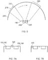
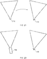
- Figure 10 schematically illustrates the capture of an image by a camera and Figure 11 schematically illustrates the re-projection of the captured image.
- a camera 500 captures an image of a portion 510 of a real-world scene.
- the field of view of the camera 500 is shown schematically as a generally triangular shape 520, such that the camera is at one apex of the generally triangular shape, the sides adjacent to the camera schematically indicate the left and right extremes of the field of view and the side opposite the camera schematically illustrates the portion of the scene which is captured.
- This schematic notation will be used in several of the following drawings.
- the view matrix may refer to the camera's position and/or orientation in space, either relative to a notional fixed point and orientation or expressed as changes with respect to the position and/or orientation applicable at a previous time (which may be the time associated with a preceding captured image, for example).
- the view matrix could be considered as the x, y and z spatial position of the camera along with its rotational orientation expressed as yaw, pitch and roll (general terms indicative of three orthogonal rotational degrees of freedom) and its viewing frustum (a general term indicative of the field of view of the camera, ranging between a wide-angle field of view and a narrow angle or telephoto field of view, and which may be expressed as an angular range corresponding to, for example, the angle 530 shown in Figure 10 ).
- the view matrix data need not comprise all of these data contributions. For example, in some arrangements, only a lateral rotational orientation (yaw) may be relevant.
- the choice of which data items to include within the view matrix data is therefore a matter for the system designer, taking into account the expected uses of the captured images and view matrix data.
- the view matrix data is stored in association with the captured image, for example as so-called metadata which is stored and/or transmitted as part of the overall image data package, for example by a camera apparatus such as that described below with reference to Figure 27 comprising an image capture device for capturing an image; a position and/or orientation detector for detecting the position and/or orientation of the camera apparatus at the time of capture of the image; and a metadata generator for associating metadata with the image, the metadata indicating the detected position and/or orientation of the camera apparatus at the time of capture of the image.
- a camera apparatus such as that described below with reference to Figure 27 comprising an image capture device for capturing an image; a position and/or orientation detector for detecting the position and/or orientation of the camera apparatus at the time of capture of the image; and a metadata generator for associating metadata with the image, the metadata indicating the detected position and/or orientation of the camera apparatus at the time of capture of the image.
- the camera 500 may be a stills camera or a video camera capturing a succession of images, separated by time intervals.
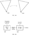
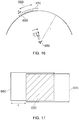
- Figure 11 schematically illustrates the re-projection of the image captured by the camera of Figure 10 according to a viewpoint of a viewer.
- the viewpoint 540 is schematically illustrated by an eye symbol and a generally triangular shape 550 which is similar to the triangular shape 520 discussed above.
- a process is carried out which relates the view matrix (as discussed above) of the viewpoint to the view matrix of the camera 500. Examples of such techniques will be described with reference to Figures 12 and 13 . Further examples are discussed in Seitz: "Image Based Transformation of Viewpoint and Scene Appearance", PhD Dissertation, Computer Sciences Department Technical Report 1354, University of Wisconsin - Madison, October 1997 .
- Figure 12 schematically illustrates an image rotation from a first view matrix 560 to a second view matrix 570.
- Re-projection of this type involves simply rotating and scaling the image so as to correct for any differences in field of view and orientation between the view matrix of the camera and the view matrix of the user viewpoint. Examples of this type of re-projection will be discussed below with reference to Figures 16 and 17 .
- Figure 13 schematically illustrates an image rotation and translation from a first view matrix 580 to eight second view matrix 590.
- the processing is slightly more involved, and may also use a depth map, indicating the image depth of different image features in the captured image, to allow the user viewpoint to be translated with respect to the viewpoint of the camera. Examples of the use of a depth map will be discussed below with reference to Figures 18-20 .
- Figure 14 schematically illustrates a latency issue with HMD image display.
- the position and/or orientation of an HMD can be used, for example as discussed with reference to Figure 9 , so that an image for display is rendered according to the detected position and/or orientation of the HMD.
- the arrangement discussed with reference to Figure 9 involves detecting the current position and/or orientation of the HMD and rendering an appropriate image for display.
- FIG 14 consider a situation in which the user's viewpoint is rotating (in a clockwise direction as illustrated schematically in Figure 14 ) from a first viewpoint 600 to a second viewpoint 610, over the course of a time interval of the order of an image repetition period of the image displays used in the HMD (for example, 1/25 second). Note that the two representations in Figure 14 are shown side-by-side, but this is for the purposes of the drawing rather than necessarily indicating a translation of the user viewpoint (although some translation could be involved between the two viewpoints).
- the position and/or orientation of the HMD is detected when the HMD is at the viewpoint 600.
- the next image for display is then rendered, but by the time that image is actually displayed, the viewpoint has rotated to the viewpoint 610.
- the result is that the image is displayed is incorrect for the user's viewpoint 610 at the time that image is displayed. This can provide a subjectively poorer experience for the user, and may possibly lead to disorientation or even nausea on the part of the user.
- Figure 15 is a schematic flow chart illustrating an image processing technique. The technique will first be discussed at a high level, and then more detail will be given below.
- the features of the technique shown in Figure 15 involve capturing or rendering an image (at a step of 620) according to the view matrix of the camera (in the case of a captured image) or the view matrix of the HMD (in the case of an image rendered by, for example, a computer game).
- the image would be rendered according to the view matrix corresponding to the viewpoint 600 in Figure 14 .
- the technique involves detecting an initial position and/or orientation of the viewer's head and generating an image for display according to the detected position and/or orientation.
- the image is then transmitted or passed to the HMD along with metadata defining that view matrix (that is to say, the view matrix according to which the image was captured or first rendered).
- the HMD view matrix is again detected (in other words, detecting a current position and/or orientation of the viewer's head at a time at which the image is to be displayed) and, at a step 630, the image is re-projected based on the metadata indicating the original view matrix and the view matrix detected from the HMD at the time of display (in the terminology of Figure 14 , this would be the view matrix corresponding to the viewpoint 610, so that the technique involves associating metadata with the generated image, the metadata indicating the initial position and/or orientation of the viewer's head). So, the technique involves re-projecting the generated image according to any differences between the initial position and/or orientation and the current position and/or orientation of the viewer's head and displaying the re-projected image using the display.
- the view matrix of the camera is generally not within the control of the display arrangements and so this technique provides a way of compensating for differences between the two view matrices.
- image rendering however, the issues are slightly different.
- a significant feature is that the time taken to process a re-projection operation can be much less than the time taken for a full rendering operation to generate an output image.
- the rendering operation takes place relative to a viewpoint (such as the viewpoint 600) which is correct at the time that the rendering operation is initiated, but the viewpoint is then adjusted (to the viewpoint 610, for example) at the time of display.
- a viewpoint such as the viewpoint 600
- the viewpoint is then adjusted (to the viewpoint 610, for example) at the time of display.
- the technique can involve receiving an image and associated metadata, detecting a current position and/or orientation of the viewer's head at a time at which the image is to be displayed, re-projecting the received image according to any differences between the position and/or orientation indicated by the metadata and the current position and/or orientation of the viewer's head, and displaying the re-projected image.
- the timing of the process can proceed as follows: At a time t 0 , the HMD view matrix data (representing the HMD's position at t 0 ) is detected. the step 620 is initiated and takes a period T render .
- the image is then transferred to the HMD. This can take a period of zero or more seconds (the period would be zero if, for example, the image had been rendered at the HMD). But in general, a period T delivery is noted for the time taken to deliver the image to the HMD ready for display.
- the HMD view matrix data is again detected. This could correspond to the required display time, in which case (according to the derivation below) the image would be displayed late by an amount T reproj , or it could be carried out at a time equal to a display time T display - T reproj . In either case it is carried out at a time dependent upon a required display time.
- the image is then re-projected (at the step 630) to account for differences between the initial and the latest view matrices.
- the time period taken for the re-projection is T reproj , assumed here to be much less than (or at least less than) T render .
- the image is then displayed at a time: t 0 + T render + T delivery + T reporoj .
- the detected initial position is detected at a latest time, allowing for the image generating latency and the image re-projection latency, to allow for the display of the re-projected image at the display time.
- Figure 16 schematically illustrates the rotation of an HMD viewpoint 650 in a clockwise direction.
- Figure 16 is similar to Figure 6 discussed above, in that the image for display is considered to lie on the surface of a sphere of radius r, where r is substantially equal to the distance from the user's eye to the virtual image generated by the HMD display system. Under this arrangement, a rotation of the viewpoint 650 by an angle ⁇ can be considered as a lateral movement on the surface of the sphere of radius r by a lateral distance d. Such a displacement d is schematically illustrated in Figure 17 . If it is assumed that an image generated at the step 620 is represented by an image 660 in Figure 16 , and an image generated at this step 630 is represented by an image 670 in Figure 16 , it may be seen that the two images may be represented side-by-side from the point of view of the user. (Note that in Figure 17 , a small vertical displacement is shown just to allow the different images to be distinguished from one another in the drawing).
- a "subtraction" operation is carried out, which is a schematic term to illustrate the operation of detecting the overlap between the required display position of the image 670 and the actual position of the image 660, so as to display within the image 670 the overlapping portion 680 (shaded in Figure 17 ) of the image 660.
- the re-projecting comprises detecting an overlapping portion between the generated image and the required re-projected image, and reproducing the overlapping portion as part of the re-projected image.
- the missing areas in the image 670 are masked or filled in using image data from a panoramic image captured or prepared for this purpose and stored by the display arrangement. So, embodiments of the technique therefore comprise filling portions of the re-projected image other than the overlapping portion with image material from a further image source.
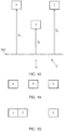
- Figure 18 schematically illustrates a depth map which may be derived, for example, from image data captured by a 3-D (binocular) camera or a so-called Z-camera, or which may be generated as part of the operation of a computer games machine's rendering engine.
- FIG. 18 In the schematic example of Figure 18 , three image objects labelled as objects A, B and C, are shown at respective image depths measured from an arbitrary depth position 700 of z A , z B and z C . Two potential viewpoints are shown, labelled as a viewpoint v 1 and a viewpoint v 2 respectively.
- Figures 19 and 20 schematically illustrate portions of images according to the viewpoint v 1 and the viewpoint v 2 respectively.
- the depth of each of the image objects is taken into account in generating the images.
- this technique can also be used at a re-projection stage such as that defined by the step 630 discussed above, so that image objects may be moved relative to one another in the re-projected image according to their respective image depths.
- the technique can involve providing depth data indicating the image depth of one or more image features, and the re-projecting can comprise repositioning one or more image features within the re-projected image according to the depth data.
- Figure 21 schematically illustrates a technique for image rendering and re-projection to compensate for HMD motion.
- a user viewpoint moves or rotates from a viewpoint 710, detected as part of the step 620 of Figure 15 , to a viewpoint 720 detected as part of the step 630 of Figure 15 and according to which the image for display is re-projected. In this way, an image according to the correct viewpoint 720 is displayed to the user.
- Figure 22 is a schematic flowchart relating to the technique shown in Figure 21 .
- process steps 800, 810, 820, 830, 840 and 850 are shown.
- the steps 800, 810 and 820 correspond generally to the step 620 of Figure 15 .
- the remaining steps 830, 840 and 850 correspond generally to the step 630 of Figure 15 .
- each of the steps in Figure 22 could be carried out immediately (or substantially immediately) in response to completion of the preceding step.
- the current position of the HMD (corresponding to the position 710 of Figure 21 ) is detected and, at the step 810, is stored (for example in a temporary working memory forming part of the HMD or the computer games machine).
- an image for display is rendered according to the viewpoint 710.
- the HMD position is again detected at the step 830 which, in this example, will detect the position 720.
- the image for display is re-projected as discussed above at the step 840 and is displayed to the user at the step 850.
- the timing of the steps could be in accordance with the example timings discussed above.
- Figure 23 schematically illustrates a technique for image capturing and re-projection to compensate for different camera and HMD positions.
- a camera viewpoint 730 is different to an HMD viewpoint 740.
- Figure 24 is a schematic flowchart relating to the technique shown in Figure 23 .
- process steps 900, 910, 920, 930, 940 and 950 are shown. Of these, the steps 900 and 910 correspond generally to the step 620 of Figure 15 . The remaining steps 920, 930, 940 and 950 correspond generally to the step 630 of Figure 15 .
- the current position of the camera (corresponding to the position 730 of Figure 23 ) is detected and, at the step 910, is transmitted as metadata along with the captured image.
- the HMD position is detected at the step 920 which, in this example, will detect the position 740.
- the image for display is re-projected as discussed above at the step 930 and is rendered (at the step 940) for display to the user at the step 950.
- Figure 25 schematically illustrates the viewing of a panoramic image 1030 formed by combining or stitching together images captured by respective cameras or camera positions 1000, 1010, 1020.
- This arrangement does not itself represent an embodiment of the present invention.
- real cameras do not have to be involved; the panoramic image could be formed by stitching together multiple computer-generated images having different respective viewpoints.
- the viewpoint of each of the cameras, camera positions or virtual cameras used to capture the panoramic image is associated with the panoramic image or the respective image portion corresponding to that viewpoint as image metadata, in a similar manner to the step 910 discussed above.
- an image 1050 for display is generated by re-projecting the respective image portions or the whole panoramic image according to the techniques discussed above.
- Figure 26 schematically illustrates camera viewpoint adjustment in a displayed image, which can allow images to be reproduced at their original size and position relative to the viewer. This arrangement does not itself represent an embodiment of the present invention.
- the left side of Figure 26 schematically illustrates a user capturing an image of (in this example) a tall building using a hand-held camera. As discussed above, the camera viewpoint is recorded and associated with the captured image as metadata.
- a user is doing the captured image by an HMD. The captured image is re-projected according to the user's viewpoint using the techniques discussed above.
- the data-processing operations described above may be carried out at the video signal source 80 (for example, a computer games machine) and/or the HMD (in terms of all of the steps of Figure 22 and the steps 920..950 of Figure 24 ).
- the division between processing at the HMD and processing at the source 80 is a matter for the system designer; it may be desirable to reduce the size, weight and power consumption of the HMD for user comfort, which would make it appropriate to move as much processing as possible to the source 80.
- some of the processing may take place entirely at the HMD. In either instance, the processing may be carried out by appropriate programmable hardware operating under software control, for example.
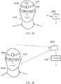
- Figure 27 schematically illustrates a camera 1100 having this functionality.
- the camera 1100 comprises a lens arrangement 1110, and image sensor 1120 arranged to receive light through the lens arrangement 1110 and convert the light into an image signal, a position, orientation and/or motion detector 1130, which may be of the types discussed above in connection with detecting the HMD's position, orientation and/or motion, and a processor 1140 operable to carry out at least the steps 900, 910 using data from the detector 1130 and to output an image signal 1150 having associated viewpoint metadata as discussed above. Note that if optical flow motion detection is used as described earlier, the image data for this process may be simply derived from the sensor 1120, so avoiding the need for a separate detector 1130.
- FIG 28 schematically illustrates a viewer 1200 observing a display screen 1210.
- the display screen 1210 may be a forward-projection screen (in which case one or more projectors, not shown, may be positioned on the same side of the screen 1210 as the user), or a rear-projection screen (in which case one or more projectors, not shown, may be positioned on the other side of the screen to that of the user) or formed as one or more display panels such as liquid crystal display (LCD) panels.
- LCD liquid crystal display
- the same techniques as discussed above can be used in respect of a larger display 1210 and a detection of the user's head orientation.
- Various ways in which the head orientation can be detected will be discussed below.
- Figure 29 schematically illustrates a user 1300 wearing a head orientation detector 1310.
- the head orientation detector 1310 is illustrated schematically as a headband 1320 and an orientation detector 1330 mounted on the headband.
- the arrangement could be made more discreet, for example been combined into a fitment attachable to a conventional pair of spectacles 1340 or forming part of a hat or pair of headphones.
- the orientation detector 1330 operates according to the techniques shown in Figure 8 if all the various alternatives discussed earlier in connection with the description of Figure 8 .
- the orientation detector 1330 encompasses much of the functionality of an HMD, but without the image display function.
- the orientation detector 1330 may comprise a processor to derive an orientation from whichever data source it is using (for example, images of the ambient scene or accelerometer data), so that the orientation detector 1330 transmits data indicative of the orientation to a receiver 1350, for example by a wireless link such as a Bluetooth link. Of course, a wired link could be used instead.
- the orientation detector 1330 may transmit "raw" acquired data, such as captured images of the surroundings or raw data from an accelerometer to the receiver 1350, so that the receiver 1350 (or a further downstream processing device, not shown) derives orientation information from the raw data received from the orientation detector 1330.
- Figure 30 schematically illustrates a passive head orientation detection technique.
- a video camera 1410 captures images of the user 1400 and passes the images to a processor 1420.
- the processor 1420 can operate in various ways.
- the processor 1420 can apply known face-detection techniques to detect the orientation of the user's face with respect to the camera 1410. For example, such techniques may involve comparing an image portion containing the user's face (normalised to a standard scale) to various Eigen images each indicative of characteristics of a face at a different orientation relative to the camera. The closest match amongst the Eigen images may be taken to be indicative of the current orientation of the user's face.
- the processor 1420 may be calibrated with information defining the relative orientation of the camera 1410 and the display screen in use, so as to be able to provide an output which is indicative of a current orientation of the user's face relative to the display screen.
- the user may wear one or more passive markers such as a reflective or retro reflective marker (not shown in Figure 30 ) to assist the processor 1420 in the detection of the orientation of the user's face relative to the camera.
- a reflective or retro reflective marker (not shown in Figure 30 ) to assist the processor 1420 in the detection of the orientation of the user's face relative to the camera.
- the camera 1410 may comprise a source of illumination arranged to eliminate the markers.
- the illumination may be invisible or substantially invisible to the user, for example infrared illumination.
Landscapes
- Engineering & Computer Science (AREA)
- Physics & Mathematics (AREA)
- General Physics & Mathematics (AREA)
- Multimedia (AREA)
- Signal Processing (AREA)
- Optics & Photonics (AREA)
- General Engineering & Computer Science (AREA)
- Theoretical Computer Science (AREA)
- Human Computer Interaction (AREA)
- Controls And Circuits For Display Device (AREA)
- Processing Or Creating Images (AREA)
- Instrument Panels (AREA)
Claims (12)
- Anzeigeverfahren, das ein Display verwendet, das betriebsfähig ist, um ein Bild für einen Betrachter anzuzeigen, wobei das Verfahren Folgendes umfasst:Erkennen (800) einer anfänglichen Position und/oder Orientierung des Kopfes des Betrachters;Erzeugen (820), durch eine Videosignalquelle, eines Bildes, im Folgenden als erzeugtes Bild bezeichnet, zur Anzeige gemäß der erkannten anfänglichen Position und/oder Orientierung;Erkennen (830) einer aktuellen Position und/oder Orientierung des Kopfes des Betrachters in Abhängigkeit von einem Anzeigezeitpunkt, zu dem das Bild angezeigt werden soll;Reprojizieren (840) des erzeugten Bildes gemäß beliebigen Differenzen zwischen der anfänglichen Position und/oder Orientierung und der aktuellen Position und/oder Orientierung des Kopfes des Betrachters durch einen Bild-Reprojektor, bei dem der Schritt des Reprojizierens das Erkennen eines überlappenden Abschnitts zwischen dem erzeugten Bild und dem erforderlichen reprojizierten Bild umfasst, undReproduzieren des überlappenden Abschnitts als Teil des reprojizierten Bildes;Speichern eines Panoramabildes, um eine weitere Bildquelle bereitzustellen, um andere Abschnitte des reprojizierten Bildes als den überlappenden Abschnitt zu füllen, wobei das Panoramabild zu diesem Zweck erfasst oder vorbereitet wurde;Füllen von Abschnitten des reprojizierten Bildes außer dem überlappenden Abschnitt mit Bildmaterial aus der weiteren Bildquelle; undAnzeigen (850) des reprojizierten Bildes unter Verwendung des Displays, bei dem der Erzeugungsschritt das Verknüpfen von Metadaten mit dem erzeugten Bild umfasst, wobei die Metadaten die anfängliche Position und/oder Orientierung des Kopfes des Betrachters angeben.
- Verfahren gemäß einem beliebigen der vorhergehenden Ansprüche, bei dem der Erzeugungsschritt das Bereitstellen von Tiefendaten umfasst, die die Bildtiefe eines oder mehrerer Bildmerkmale angeben, und der Schritt der Reprojektion das Neupositionieren eines oder mehrerer Bildmerkmale innerhalb des reprojizierten Bildes gemäß den Tiefendaten umfasst.
- Verfahren gemäß einem beliebigen der vorhergehenden Ansprüche, bei dem das Display ein kopfmontierbares Display ist und die Position und/oder Orientierung des Kopfes des Betrachters durch Erkennen einer Position und/oder Orientierung des kopfmontierbaren Displays erkannt wird.
- Verfahren gemäß einem beliebigen der vorhergehenden Ansprüche, bei dem der Erzeugungsschritt eine Zeitspanne in Anspruch nimmt, die mindestens einer Bilderzeugungslatenz entspricht, und der Reprojektionsschritt eine Zeitspanne in Anspruch nimmt, die mindestens einer Bildreprojektionslatenz entspricht, wobei die Bilderzeugungslatenz länger als die Bildreprojektionslatenz ist.
- Verfahren gemäß Anspruch 4, bei dem die erkannte anfängliche Position zu einem spätesten Zeitpunkt erkannt wird, wobei die Bilderzeugungslatenz und die Reprojektionslatenz des Bildes gestatten, dass das reprojizierte Bild zum Anzeigezeitpunkt angezeigt wird.
- Computer-Software zum Ausführen eines Verfahrens gemäß einem beliebigen der vorhergehenden Ansprüche.
- Anzeigesystem, das Folgendes umfasst:ein Anzeigeelement (150), das von einem Betrachter beobachtet werden kann;einen Positions- und/oder Orientierungsdetektor (450, 420) zum Erkennen der Position und/oder Orientierung des Kopfes des Betrachters;eine Videosignalquelle (620) zum Erzeugen eines Bildes, im Folgenden als erzeugtes Bild bezeichnet, zur Anzeige gemäß einer anfänglichen Position und/oder Orientierung des Kopfes des Betrachters;einen Bild-Reprojektor (630) zum Empfangen des erzeugten Bildes und zum Reprojizieren des erzeugten Bildes zur Anzeige durch das Anzeigeelement gemäß beliebigen Differenzen zwischen der Position und/oder Orientierung, die für die Erzeugung des Bildes anwendbar sind, und der aktuellen Position und/oder Orientierung des Kopfes des Betrachters, wobei der Bild-Reprojektor ausgebildet ist, um einen überlappenden Abschnitt zwischen dem erzeugten Bild und dem erforderlichen reprojizierten Bild zu erkennen;einen Speicher zum Speichern eines Panoramabildes, um eine weitere Bildquelle bereitzustellen, um andere Abschnitte des reprojizierten Bildes als den überlappenden Abschnitt zu füllen, wobei das Panoramabild zu diesem Zweck erfasst oder vorbereitet wurde;wobei der Bild-Reprojektor (630) dazu ausgebildet ist, den überlappenden Abschnitt als Teil des reprojizierten Bildes zu reproduzieren und andere Abschnitte des reprojizierten Bildes als den überlappenden Abschnitt mit Bildmaterial aus der weiteren Bildquelle zu füllen, wobei die Videosignalquelle dazu ausgebildet ist, dem erzeugten Bild Metadaten zuzuordnen, wobei die Metadaten die anfängliche Position und/oder Orientierung des Kopfes des Betrachters angeben.
- System gemäß Anspruch 7, bei dem die Videosignalquelle eine Videospiel- oder Datenverarbeitungsmaschine ist.
- System gemäß Anspruch 7 oder Anspruch 8, bei dem der Positions- und/oder Orientierungsdetektor Folgendes umfasst:eine Kamera (320), die so montiert ist, dass sie sich mit dem Kopf des Benutzers bewegt; undeinen Bildvergleicher (410), der betriebsfähig ist, um sukzessive Bilder, die von der Kamera erfasst wurden, zu vergleichen, um eine Bewegung zwischen den Bildern zu erkennen.
- System gemäß Anspruch 7 oder Anspruch 8, bei dem der Positions- und/oder Orientierungsdetektor einen Beschleunigungsmesser (450) umfasst.
- System gemäß Anspruch 7 oder Anspruch 8, bei dem das Anzeigeelement einen Teil eines kopfmontierbaren Displays (10) mit einem auf dem Kopf eines Betrachters zu montierenden Rahmen (40) bildet, wobei der Rahmen eine oder zwei Anzeigepositionen für das Auge definiert, die im Gebrauch vor einem jeweiligen Auge des Betrachters positioniert sind, und ein jeweiliges Anzeigeelement in Bezug auf jede der Anzeigepositionen für das Auge montiert ist, wobei das Anzeigeelement ein virtuelles Bild einer Videoanzeige eines Videosignals von einer Videosignalquelle für dieses Auge des Betrachters bereitstellt.
- System gemäß Anspruch 11, bei dem im Gebrauch das virtuelle Bild in einem Abstand von mehr als einem Meter zum Rahmen erzeugt wird.
Priority Applications (1)
| Application Number | Priority Date | Filing Date | Title |
|---|---|---|---|
| EP21211371.6A EP4012482A1 (de) | 2013-03-25 | 2014-03-24 | Anzeige |
Applications Claiming Priority (4)
| Application Number | Priority Date | Filing Date | Title |
|---|---|---|---|
| GBGB1305402.8A GB201305402D0 (en) | 2013-03-25 | 2013-03-25 | Head mountable display |
| GB1308151.8A GB2512404A (en) | 2013-03-25 | 2013-05-07 | Display |
| GB1404739.3A GB2514466B (en) | 2013-03-25 | 2014-03-17 | Display |
| PCT/GB2014/050905 WO2014155072A2 (en) | 2013-03-25 | 2014-03-24 | Display |
Related Child Applications (1)
| Application Number | Title | Priority Date | Filing Date |
|---|---|---|---|
| EP21211371.6A Division EP4012482A1 (de) | 2013-03-25 | 2014-03-24 | Anzeige |
Publications (2)
| Publication Number | Publication Date |
|---|---|
| EP2979127A2 EP2979127A2 (de) | 2016-02-03 |
| EP2979127B1 true EP2979127B1 (de) | 2021-12-01 |
Family
ID=48326595
Family Applications (2)
| Application Number | Title | Priority Date | Filing Date |
|---|---|---|---|
| EP21211371.6A Pending EP4012482A1 (de) | 2013-03-25 | 2014-03-24 | Anzeige |
| EP14715401.7A Active EP2979127B1 (de) | 2013-03-25 | 2014-03-24 | Anzeigeverfahren und -system |
Family Applications Before (1)
| Application Number | Title | Priority Date | Filing Date |
|---|---|---|---|
| EP21211371.6A Pending EP4012482A1 (de) | 2013-03-25 | 2014-03-24 | Anzeige |
Country Status (5)
| Country | Link |
|---|---|
| US (1) | US10054796B2 (de) |
| EP (2) | EP4012482A1 (de) |
| CN (1) | CN105103034B (de) |
| GB (3) | GB201305402D0 (de) |
| WO (1) | WO2014155072A2 (de) |
Families Citing this family (72)
| Publication number | Priority date | Publication date | Assignee | Title |
|---|---|---|---|---|
| GB201310359D0 (en) * | 2013-06-11 | 2013-07-24 | Sony Comp Entertainment Europe | Head-Mountable apparatus and systems |
| US20150228119A1 (en) | 2014-02-11 | 2015-08-13 | Osterhout Group, Inc. | Spatial location presentation in head worn computing |
| US9766463B2 (en) | 2014-01-21 | 2017-09-19 | Osterhout Group, Inc. | See-through computer display systems |
| US9753288B2 (en) | 2014-01-21 | 2017-09-05 | Osterhout Group, Inc. | See-through computer display systems |
| US9852545B2 (en) | 2014-02-11 | 2017-12-26 | Osterhout Group, Inc. | Spatial location presentation in head worn computing |
| US12112089B2 (en) | 2014-02-11 | 2024-10-08 | Mentor Acquisition One, Llc | Spatial location presentation in head worn computing |
| US20160187651A1 (en) | 2014-03-28 | 2016-06-30 | Osterhout Group, Inc. | Safety for a vehicle operator with an hmd |
| GB2528699B (en) | 2014-07-29 | 2017-05-03 | Sony Computer Entertainment Europe Ltd | Image processing |
| US20160037134A1 (en) * | 2014-07-31 | 2016-02-04 | Todd MEDEMA | Methods and systems of simulating time of day and environment of remote locations |
| US9686520B2 (en) * | 2015-01-22 | 2017-06-20 | Microsoft Technology Licensing, Llc | Reconstructing viewport upon user viewpoint misprediction |
| US10127714B1 (en) * | 2015-01-27 | 2018-11-13 | Google Llc | Spherical three-dimensional video rendering for virtual reality |
| GB2534921B (en) * | 2015-02-06 | 2021-11-17 | Sony Interactive Entertainment Inc | Head-mountable display system |
| US20160239985A1 (en) | 2015-02-17 | 2016-08-18 | Osterhout Group, Inc. | See-through computer display systems |
| US10878775B2 (en) | 2015-02-17 | 2020-12-29 | Mentor Acquisition One, Llc | See-through computer display systems |
| JP6540108B2 (ja) * | 2015-03-09 | 2019-07-10 | 富士通株式会社 | 画像生成方法、システム、装置、及び端末 |
| EP3289430B1 (de) | 2015-04-27 | 2019-10-23 | Snap-Aid Patents Ltd. | Schätzung und verwendung einer relativen kopfhaltung und kamerasichtfeld |
| US11252399B2 (en) | 2015-05-28 | 2022-02-15 | Microsoft Technology Licensing, Llc | Determining inter-pupillary distance |
| US9746675B2 (en) | 2015-05-28 | 2017-08-29 | Microsoft Technology Licensing, Llc | Alignment based view matrix tuning |
| US9658686B2 (en) | 2015-05-28 | 2017-05-23 | Microsoft Technology Licensing, Llc | Motion based view matrix tuning |
| KR101716326B1 (ko) | 2015-09-08 | 2017-03-14 | 클릭트 주식회사 | 가상현실영상 전송방법, 재생방법 및 이를 이용한 프로그램 |
| KR102501752B1 (ko) * | 2015-09-21 | 2023-02-20 | 삼성전자주식회사 | 헤드 마운트 디스플레이의 움직임을 보상하는 방법 및 이를 위한 장치 |
| JP6548821B2 (ja) * | 2015-09-30 | 2019-07-24 | 株式会社ソニー・インタラクティブエンタテインメント | ヘッドマウントディスプレイの画面上でコンテンツの配置を最適化する方法 |
| US10694115B2 (en) * | 2015-09-30 | 2020-06-23 | Huawei Technologies Co., Ltd. | Method, apparatus, and terminal for presenting panoramic visual content |
| GB2543320B (en) * | 2015-10-14 | 2020-05-13 | Sony Interactive Entertainment Inc | Head-mountable display system |
| US9781342B1 (en) | 2015-10-22 | 2017-10-03 | Gopro, Inc. | System and method for identifying comment clusters for panoramic content segments |
| WO2017083420A1 (en) * | 2015-11-10 | 2017-05-18 | Thales Visionix, Inc. | Robust vision-inertial pedestrian tracking with heading auto-alignment |
| CN105915877A (zh) * | 2015-12-27 | 2016-08-31 | 乐视致新电子科技(天津)有限公司 | 一种三维视频的自由观影方法及设备 |
| WO2017120906A1 (zh) * | 2016-01-15 | 2017-07-20 | 赵政荣 | 游戏时的专利信息提醒方法和头戴虚拟设备 |
| US10317991B2 (en) | 2016-02-09 | 2019-06-11 | Google Llc | Pixel adjusting at display controller for electronic display stabilization |
| US10591728B2 (en) | 2016-03-02 | 2020-03-17 | Mentor Acquisition One, Llc | Optical systems for head-worn computers |
| US10667981B2 (en) | 2016-02-29 | 2020-06-02 | Mentor Acquisition One, Llc | Reading assistance system for visually impaired |
| CN105955454A (zh) * | 2016-04-15 | 2016-09-21 | 北京小鸟看看科技有限公司 | 一种用于虚拟现实系统的防眩晕方法和装置 |
| CN105892683A (zh) * | 2016-04-29 | 2016-08-24 | 上海乐相科技有限公司 | 一种显示方法及目标设备 |
| US11182930B2 (en) * | 2016-05-02 | 2021-11-23 | Waves Audio Ltd. | Head tracking with adaptive reference |
| SE540058C2 (en) * | 2016-05-10 | 2018-03-06 | Bae Systems Haegglunds Ab | Method and system for facilitating transportation of an observer in a vehicle |
| JP2017208688A (ja) * | 2016-05-18 | 2017-11-24 | 株式会社スクウェア・エニックス | プログラム、コンピュータ装置、プログラム実行方法、及び、コンピュータシステム |
| EP3473011A1 (de) * | 2016-06-21 | 2019-04-24 | Signify Holding B.V. | Anzeigesystem und -verfahren |
| CN106170082A (zh) * | 2016-06-30 | 2016-11-30 | 深圳市虚拟现实科技有限公司 | 远程全景图像实时全方位传输和显示方法 |
| CN106131647B (zh) * | 2016-07-18 | 2019-03-19 | 杭州当虹科技有限公司 | 一种基于虚拟现实视频的多画面同时观看方法 |
| CN106094210A (zh) * | 2016-08-05 | 2016-11-09 | 江苏艾锐泰克无人飞行器科技有限公司 | 一种手机大屏呈像装置和航拍系统 |
| JP6228640B1 (ja) * | 2016-08-17 | 2017-11-08 | 株式会社コロプラ | 表示制御方法および当該表示制御方法をコンピュータに実行させるためのプログラム |
| CN106331823B (zh) * | 2016-08-31 | 2019-08-20 | 北京奇艺世纪科技有限公司 | 一种视频播放方法及装置 |
| CN106445129A (zh) * | 2016-09-14 | 2017-02-22 | 乐视控股(北京)有限公司 | 全景图像信息显示方法、装置及系统 |
| KR102630681B1 (ko) * | 2016-10-11 | 2024-01-30 | 삼성전자주식회사 | 디스플레이 장치 및 캡처 이미지 생성 방법 |
| CN106782260B (zh) * | 2016-12-06 | 2020-05-29 | 歌尔科技有限公司 | 用于虚拟现实运动场景的显示方法及装置 |
| GB2558280A (en) * | 2016-12-23 | 2018-07-11 | Sony Interactive Entertainment Inc | Head mountable display system |
| US9992461B1 (en) * | 2017-02-08 | 2018-06-05 | Hyundai Motor Company | Projection orientation correction system for vehicle |
| KR101874111B1 (ko) * | 2017-03-03 | 2018-07-03 | 클릭트 주식회사 | 가상현실영상 재생방법 및 이를 이용한 프로그램 |
| WO2018167532A1 (fr) * | 2017-03-13 | 2018-09-20 | Spondeo Group Sa | Procédé de génération de données multimédia associée à un système de sport |
| CN106970467B (zh) * | 2017-03-28 | 2020-03-24 | 联想(北京)有限公司 | 信息显示方法及头戴式显示设备 |
| WO2018212617A1 (en) * | 2017-05-18 | 2018-11-22 | Samsung Electronics Co., Ltd. | Method for providing 360-degree video and device for supporting the same |
| JP2019079193A (ja) * | 2017-10-23 | 2019-05-23 | キヤノン株式会社 | 情報処理装置、撮像装置、プログラム及び撮像システム |
| US11119331B2 (en) * | 2018-03-28 | 2021-09-14 | Disney Enterprises, Inc. | Method for dampening projector vibration |
| US10520739B1 (en) * | 2018-07-11 | 2019-12-31 | Valve Corporation | Dynamic panel masking |
| US11080822B2 (en) | 2018-12-21 | 2021-08-03 | Htc Corporation | Method, system and recording medium for building environment map |
| CN112148115A (zh) | 2019-06-28 | 2020-12-29 | 中兴通讯股份有限公司 | 媒体处理方法、装置、系统和可读存储介质 |
| GB2585198B (en) | 2019-07-01 | 2022-03-02 | Sony Interactive Entertainment Inc | Method and device for generating video frames |
| EP4062380A4 (de) | 2019-11-18 | 2023-11-29 | Magic Leap, Inc. | Kartieren und lokalisieren einer begehbaren welt |
| US11150470B2 (en) | 2020-01-07 | 2021-10-19 | Microsoft Technology Licensing, Llc | Inertial measurement unit signal based image reprojection |
| US11574424B2 (en) | 2020-01-27 | 2023-02-07 | Magic Leap, Inc. | Augmented reality map curation |
| US11860439B1 (en) | 2020-05-06 | 2024-01-02 | Apple Inc. | Head-mounted electronic device with alignment sensors |
| US12069230B2 (en) * | 2020-12-23 | 2024-08-20 | Meta Platforms Technologies, Llc | Temporal foveated rendering |
| GB2602841B (en) * | 2021-01-19 | 2024-09-11 | Sony Interactive Entertainment Inc | Image generation system and method |
| US12086308B2 (en) * | 2021-01-20 | 2024-09-10 | Magna Electronics Inc. | Vehicular driver assist system with adjustable display |
| US11622100B2 (en) * | 2021-02-17 | 2023-04-04 | flexxCOACH VR | 360-degree virtual-reality system for dynamic events |
| US11544896B2 (en) | 2021-05-14 | 2023-01-03 | Zoox, Inc. | Spatial and temporal upsampling techniques for simulated sensor data |
| US11715257B2 (en) | 2021-05-14 | 2023-08-01 | Zoox, Inc. | Simulation view generation based on simulated sensor operations |
| US11430177B1 (en) * | 2021-05-14 | 2022-08-30 | Zoox, Inc. | Mapping simulated sensors to simulated environment views |
| US11741661B2 (en) | 2021-05-14 | 2023-08-29 | Zoox, Inc. | Sensor simulation with unified multi-sensor views |
| CN118302717A (zh) | 2021-10-20 | 2024-07-05 | 南特工作室有限责任公司 | 经由动态视角的相机跟踪 |
| WO2023147236A1 (en) | 2022-01-26 | 2023-08-03 | Apple Inc. | Storage systems with calibration capabilities |
| US20250095290A1 (en) * | 2023-09-18 | 2025-03-20 | Dark Arts Software LLC | System for mitigating convergence insufficiency in virtual reality displays |
Citations (3)
| Publication number | Priority date | Publication date | Assignee | Title |
|---|---|---|---|---|
| EP0709816A2 (de) * | 1994-10-28 | 1996-05-01 | Canon Kabushiki Kaisha | Anzeigevorrichtung und ihre Kontrollmethode |
| US20050156817A1 (en) * | 2002-08-30 | 2005-07-21 | Olympus Corporation | Head-mounted display system and method for processing images |
| EP2211224A1 (de) * | 2009-01-27 | 2010-07-28 | Thomson Licensing SA | Datenhelm und zugehöriges Betriebsverfahren |
Family Cites Families (27)
| Publication number | Priority date | Publication date | Assignee | Title |
|---|---|---|---|---|
| NL8301864A (nl) * | 1983-05-26 | 1984-12-17 | Philips Nv | Hoofdtelevisie ofwel inrichting voor het individueel weergeven van beelden. |
| US5566073A (en) | 1994-07-11 | 1996-10-15 | Margolin; Jed | Pilot aid using a synthetic environment |
| US5742264A (en) | 1995-01-24 | 1998-04-21 | Matsushita Electric Industrial Co., Ltd. | Head-mounted display |
| US6552744B2 (en) * | 1997-09-26 | 2003-04-22 | Roxio, Inc. | Virtual reality camera |
| GB2372169B (en) * | 1999-09-22 | 2004-05-26 | Canadian Space Agency | Method and system for time/motion compensation for head mounted displays |
| US7312766B1 (en) * | 2000-09-22 | 2007-12-25 | Canadian Space Agency | Method and system for time/motion compensation for head mounted displays |
| JP3620537B2 (ja) * | 2003-05-02 | 2005-02-16 | セイコーエプソン株式会社 | 画像処理システム、プロジェクタ、プログラム、情報記憶媒体および画像処理方法 |
| CN100416336C (zh) * | 2003-06-12 | 2008-09-03 | 美国西门子医疗解决公司 | 校准真实和虚拟视图 |
| WO2005093493A1 (ja) | 2004-03-29 | 2005-10-06 | Sony Corporation | 光学装置及び虚像表示装置 |
| US7259758B2 (en) * | 2004-06-21 | 2007-08-21 | Microsoft Corporation | System and method for reducing latency in display of computer-generated graphics |
| US9323055B2 (en) * | 2006-05-26 | 2016-04-26 | Exelis, Inc. | System and method to display maintenance and operational instructions of an apparatus using augmented reality |
| CN201145773Y (zh) * | 2008-01-24 | 2008-11-05 | 寇开泰 | 眼镜式显示器 |
| JP4674634B2 (ja) | 2008-12-19 | 2011-04-20 | ソニー株式会社 | 頭部装着型ディスプレイ |
| US20100156907A1 (en) * | 2008-12-23 | 2010-06-24 | Microsoft Corporation | Display surface tracking |
| CN102484730A (zh) * | 2009-06-04 | 2012-05-30 | 寇平公司 | 集成头戴显示器的3-d视频处理器 |
| US9366862B2 (en) * | 2010-02-28 | 2016-06-14 | Microsoft Technology Licensing, Llc | System and method for delivering content to a group of see-through near eye display eyepieces |
| US20120188148A1 (en) * | 2011-01-24 | 2012-07-26 | Microvision, Inc. | Head Mounted Meta-Display System |
| JP5784818B2 (ja) * | 2011-03-29 | 2015-09-24 | クアルコム,インコーポレイテッド | 拡張現実システムにおける実世界表面への仮想画像のアンカリング |
| US8836771B2 (en) * | 2011-04-26 | 2014-09-16 | Echostar Technologies L.L.C. | Apparatus, systems and methods for shared viewing experience using head mounted displays |
| WO2012166593A2 (en) * | 2011-05-27 | 2012-12-06 | Thomas Seidl | System and method for creating a navigable, panoramic three-dimensional virtual reality environment having ultra-wide field of view |
| WO2013021458A1 (ja) * | 2011-08-09 | 2013-02-14 | パイオニア株式会社 | 複合現実感装置 |
| GB201116566D0 (en) * | 2011-09-26 | 2011-11-09 | Skype Ltd | Video stabilisation |
| US9087471B2 (en) * | 2011-11-04 | 2015-07-21 | Google Inc. | Adaptive brightness control of head mounted display |
| US20130135303A1 (en) * | 2011-11-28 | 2013-05-30 | Cast Group Of Companies Inc. | System and Method for Visualizing a Virtual Environment Online |
| KR101180119B1 (ko) * | 2012-02-23 | 2012-09-05 | (주)올라웍스 | 카메라 모듈을 통해 사용자의 머리를 트래킹하여 화면을 제어하는 방법, 제어장치 및 컴퓨터 판독 가능한 기록 매체 |
| US10269179B2 (en) * | 2012-10-05 | 2019-04-23 | Elwha Llc | Displaying second augmentations that are based on registered first augmentations |
| US20140240469A1 (en) * | 2013-02-28 | 2014-08-28 | Motorola Mobility Llc | Electronic Device with Multiview Image Capture and Depth Sensing |
-
2013
- 2013-03-25 GB GBGB1305402.8A patent/GB201305402D0/en not_active Ceased
- 2013-05-07 GB GB1308151.8A patent/GB2512404A/en not_active Withdrawn
-
2014
- 2014-03-17 GB GB1404739.3A patent/GB2514466B/en active Active
- 2014-03-24 CN CN201480016970.9A patent/CN105103034B/zh active Active
- 2014-03-24 EP EP21211371.6A patent/EP4012482A1/de active Pending
- 2014-03-24 US US14/778,867 patent/US10054796B2/en active Active
- 2014-03-24 EP EP14715401.7A patent/EP2979127B1/de active Active
- 2014-03-24 WO PCT/GB2014/050905 patent/WO2014155072A2/en not_active Ceased
Patent Citations (3)
| Publication number | Priority date | Publication date | Assignee | Title |
|---|---|---|---|---|
| EP0709816A2 (de) * | 1994-10-28 | 1996-05-01 | Canon Kabushiki Kaisha | Anzeigevorrichtung und ihre Kontrollmethode |
| US20050156817A1 (en) * | 2002-08-30 | 2005-07-21 | Olympus Corporation | Head-mounted display system and method for processing images |
| EP2211224A1 (de) * | 2009-01-27 | 2010-07-28 | Thomson Licensing SA | Datenhelm und zugehöriges Betriebsverfahren |
Also Published As
| Publication number | Publication date |
|---|---|
| WO2014155072A3 (en) | 2014-11-20 |
| US10054796B2 (en) | 2018-08-21 |
| WO2014155072A2 (en) | 2014-10-02 |
| CN105103034B (zh) | 2019-11-12 |
| GB2514466A (en) | 2014-11-26 |
| US20160246061A1 (en) | 2016-08-25 |
| EP4012482A1 (de) | 2022-06-15 |
| GB201305402D0 (en) | 2013-05-08 |
| GB201308151D0 (en) | 2013-06-12 |
| GB2514466B (en) | 2017-11-29 |
| GB2512404A (en) | 2014-10-01 |
| EP2979127A2 (de) | 2016-02-03 |
| GB201404739D0 (en) | 2014-04-30 |
| CN105103034A (zh) | 2015-11-25 |
Similar Documents
| Publication | Publication Date | Title |
|---|---|---|
| EP2979127B1 (de) | Anzeigeverfahren und -system | |
| EP3051525B1 (de) | Anzeige | |
| US10257492B2 (en) | Image encoding and display | |
| US10306202B2 (en) | Image encoding and display | |
| EP3070513B1 (de) | Am kopf tragbares anzeigesystem | |
| EP3008691B1 (de) | Kopfmontierbare vorrichtung und systeme | |
| EP3008548B1 (de) | Kopfmontierbare vorrichtung und systeme | |
| GB2517057A (en) | Head-mountable apparatus and systems | |
| US9372346B2 (en) | Directional light beams for angle detection | |
| US12118733B2 (en) | Apparatus and method for virtual reality | |
| GB2558283A (en) | Image processing | |
| WO2018115843A1 (en) | Head mountable display system |
Legal Events
| Date | Code | Title | Description |
|---|---|---|---|
| PUAI | Public reference made under article 153(3) epc to a published international application that has entered the european phase |
Free format text: ORIGINAL CODE: 0009012 |
|
| 17P | Request for examination filed |
Effective date: 20150829 |
|
| AK | Designated contracting states |
Kind code of ref document: A2 Designated state(s): AL AT BE BG CH CY CZ DE DK EE ES FI FR GB GR HR HU IE IS IT LI LT LU LV MC MK MT NL NO PL PT RO RS SE SI SK SM TR |
|
| AX | Request for extension of the european patent |
Extension state: BA ME |
|
| DAX | Request for extension of the european patent (deleted) | ||
| RAP1 | Party data changed (applicant data changed or rights of an application transferred) |
Owner name: SONY INTERACTIVE ENTERTAINMENT EUROPE LIMITED |
|
| STAA | Information on the status of an ep patent application or granted ep patent |
Free format text: STATUS: EXAMINATION IS IN PROGRESS |
|
| 17Q | First examination report despatched |
Effective date: 20190611 |
|
| RAP1 | Party data changed (applicant data changed or rights of an application transferred) |
Owner name: SONY INTERACTIVE ENTERTAINMENT INC. |
|
| GRAP | Despatch of communication of intention to grant a patent |
Free format text: ORIGINAL CODE: EPIDOSNIGR1 |
|
| STAA | Information on the status of an ep patent application or granted ep patent |
Free format text: STATUS: GRANT OF PATENT IS INTENDED |
|
| INTG | Intention to grant announced |
Effective date: 20210628 |
|
| GRAS | Grant fee paid |
Free format text: ORIGINAL CODE: EPIDOSNIGR3 |
|
| GRAA | (expected) grant |
Free format text: ORIGINAL CODE: 0009210 |
|
| STAA | Information on the status of an ep patent application or granted ep patent |
Free format text: STATUS: THE PATENT HAS BEEN GRANTED |
|
| AK | Designated contracting states |
Kind code of ref document: B1 Designated state(s): AL AT BE BG CH CY CZ DE DK EE ES FI FR GB GR HR HU IE IS IT LI LT LU LV MC MK MT NL NO PL PT RO RS SE SI SK SM TR |
|
| REG | Reference to a national code |
Ref country code: GB Ref legal event code: FG4D |
|
| REG | Reference to a national code |
Ref country code: AT Ref legal event code: REF Ref document number: 1452328 Country of ref document: AT Kind code of ref document: T Effective date: 20211215 Ref country code: CH Ref legal event code: EP |
|
| REG | Reference to a national code |
Ref country code: IE Ref legal event code: FG4D |
|
| REG | Reference to a national code |
Ref country code: DE Ref legal event code: R096 Ref document number: 602014081495 Country of ref document: DE |
|
| REG | Reference to a national code |
Ref country code: NL Ref legal event code: FP |
|
| REG | Reference to a national code |
Ref country code: LT Ref legal event code: MG9D |
|
| REG | Reference to a national code |
Ref country code: AT Ref legal event code: MK05 Ref document number: 1452328 Country of ref document: AT Kind code of ref document: T Effective date: 20211201 |
|
| PG25 | Lapsed in a contracting state [announced via postgrant information from national office to epo] |
Ref country code: RS Free format text: LAPSE BECAUSE OF FAILURE TO SUBMIT A TRANSLATION OF THE DESCRIPTION OR TO PAY THE FEE WITHIN THE PRESCRIBED TIME-LIMIT Effective date: 20211201 Ref country code: LT Free format text: LAPSE BECAUSE OF FAILURE TO SUBMIT A TRANSLATION OF THE DESCRIPTION OR TO PAY THE FEE WITHIN THE PRESCRIBED TIME-LIMIT Effective date: 20211201 Ref country code: FI Free format text: LAPSE BECAUSE OF FAILURE TO SUBMIT A TRANSLATION OF THE DESCRIPTION OR TO PAY THE FEE WITHIN THE PRESCRIBED TIME-LIMIT Effective date: 20211201 Ref country code: BG Free format text: LAPSE BECAUSE OF FAILURE TO SUBMIT A TRANSLATION OF THE DESCRIPTION OR TO PAY THE FEE WITHIN THE PRESCRIBED TIME-LIMIT Effective date: 20220301 Ref country code: AT Free format text: LAPSE BECAUSE OF FAILURE TO SUBMIT A TRANSLATION OF THE DESCRIPTION OR TO PAY THE FEE WITHIN THE PRESCRIBED TIME-LIMIT Effective date: 20211201 |
|
| PG25 | Lapsed in a contracting state [announced via postgrant information from national office to epo] |
Ref country code: SE Free format text: LAPSE BECAUSE OF FAILURE TO SUBMIT A TRANSLATION OF THE DESCRIPTION OR TO PAY THE FEE WITHIN THE PRESCRIBED TIME-LIMIT Effective date: 20211201 Ref country code: PL Free format text: LAPSE BECAUSE OF FAILURE TO SUBMIT A TRANSLATION OF THE DESCRIPTION OR TO PAY THE FEE WITHIN THE PRESCRIBED TIME-LIMIT Effective date: 20211201 Ref country code: NO Free format text: LAPSE BECAUSE OF FAILURE TO SUBMIT A TRANSLATION OF THE DESCRIPTION OR TO PAY THE FEE WITHIN THE PRESCRIBED TIME-LIMIT Effective date: 20220301 Ref country code: LV Free format text: LAPSE BECAUSE OF FAILURE TO SUBMIT A TRANSLATION OF THE DESCRIPTION OR TO PAY THE FEE WITHIN THE PRESCRIBED TIME-LIMIT Effective date: 20211201 Ref country code: HR Free format text: LAPSE BECAUSE OF FAILURE TO SUBMIT A TRANSLATION OF THE DESCRIPTION OR TO PAY THE FEE WITHIN THE PRESCRIBED TIME-LIMIT Effective date: 20211201 Ref country code: GR Free format text: LAPSE BECAUSE OF FAILURE TO SUBMIT A TRANSLATION OF THE DESCRIPTION OR TO PAY THE FEE WITHIN THE PRESCRIBED TIME-LIMIT Effective date: 20220302 Ref country code: ES Free format text: LAPSE BECAUSE OF FAILURE TO SUBMIT A TRANSLATION OF THE DESCRIPTION OR TO PAY THE FEE WITHIN THE PRESCRIBED TIME-LIMIT Effective date: 20211201 |
|
| PG25 | Lapsed in a contracting state [announced via postgrant information from national office to epo] |
Ref country code: SM Free format text: LAPSE BECAUSE OF FAILURE TO SUBMIT A TRANSLATION OF THE DESCRIPTION OR TO PAY THE FEE WITHIN THE PRESCRIBED TIME-LIMIT Effective date: 20211201 Ref country code: SK Free format text: LAPSE BECAUSE OF FAILURE TO SUBMIT A TRANSLATION OF THE DESCRIPTION OR TO PAY THE FEE WITHIN THE PRESCRIBED TIME-LIMIT Effective date: 20211201 Ref country code: RO Free format text: LAPSE BECAUSE OF FAILURE TO SUBMIT A TRANSLATION OF THE DESCRIPTION OR TO PAY THE FEE WITHIN THE PRESCRIBED TIME-LIMIT Effective date: 20211201 Ref country code: PT Free format text: LAPSE BECAUSE OF FAILURE TO SUBMIT A TRANSLATION OF THE DESCRIPTION OR TO PAY THE FEE WITHIN THE PRESCRIBED TIME-LIMIT Effective date: 20220401 Ref country code: EE Free format text: LAPSE BECAUSE OF FAILURE TO SUBMIT A TRANSLATION OF THE DESCRIPTION OR TO PAY THE FEE WITHIN THE PRESCRIBED TIME-LIMIT Effective date: 20211201 Ref country code: CZ Free format text: LAPSE BECAUSE OF FAILURE TO SUBMIT A TRANSLATION OF THE DESCRIPTION OR TO PAY THE FEE WITHIN THE PRESCRIBED TIME-LIMIT Effective date: 20211201 |
|
| REG | Reference to a national code |
Ref country code: DE Ref legal event code: R097 Ref document number: 602014081495 Country of ref document: DE |
|
| PG25 | Lapsed in a contracting state [announced via postgrant information from national office to epo] |
Ref country code: IS Free format text: LAPSE BECAUSE OF FAILURE TO SUBMIT A TRANSLATION OF THE DESCRIPTION OR TO PAY THE FEE WITHIN THE PRESCRIBED TIME-LIMIT Effective date: 20220401 |
|
| PLBE | No opposition filed within time limit |
Free format text: ORIGINAL CODE: 0009261 |
|
| STAA | Information on the status of an ep patent application or granted ep patent |
Free format text: STATUS: NO OPPOSITION FILED WITHIN TIME LIMIT |
|
| PG25 | Lapsed in a contracting state [announced via postgrant information from national office to epo] |
Ref country code: MC Free format text: LAPSE BECAUSE OF FAILURE TO SUBMIT A TRANSLATION OF THE DESCRIPTION OR TO PAY THE FEE WITHIN THE PRESCRIBED TIME-LIMIT Effective date: 20211201 Ref country code: DK Free format text: LAPSE BECAUSE OF FAILURE TO SUBMIT A TRANSLATION OF THE DESCRIPTION OR TO PAY THE FEE WITHIN THE PRESCRIBED TIME-LIMIT Effective date: 20211201 Ref country code: AL Free format text: LAPSE BECAUSE OF FAILURE TO SUBMIT A TRANSLATION OF THE DESCRIPTION OR TO PAY THE FEE WITHIN THE PRESCRIBED TIME-LIMIT Effective date: 20211201 |
|
| REG | Reference to a national code |
Ref country code: CH Ref legal event code: PL |
|
| 26N | No opposition filed |
Effective date: 20220902 |
|
| PG25 | Lapsed in a contracting state [announced via postgrant information from national office to epo] |
Ref country code: SI Free format text: LAPSE BECAUSE OF FAILURE TO SUBMIT A TRANSLATION OF THE DESCRIPTION OR TO PAY THE FEE WITHIN THE PRESCRIBED TIME-LIMIT Effective date: 20211201 |
|
| REG | Reference to a national code |
Ref country code: BE Ref legal event code: MM Effective date: 20220331 |
|
| PG25 | Lapsed in a contracting state [announced via postgrant information from national office to epo] |
Ref country code: LU Free format text: LAPSE BECAUSE OF NON-PAYMENT OF DUE FEES Effective date: 20220324 Ref country code: LI Free format text: LAPSE BECAUSE OF NON-PAYMENT OF DUE FEES Effective date: 20220331 Ref country code: IE Free format text: LAPSE BECAUSE OF NON-PAYMENT OF DUE FEES Effective date: 20220324 Ref country code: CH Free format text: LAPSE BECAUSE OF NON-PAYMENT OF DUE FEES Effective date: 20220331 |
|
| PG25 | Lapsed in a contracting state [announced via postgrant information from national office to epo] |
Ref country code: BE Free format text: LAPSE BECAUSE OF NON-PAYMENT OF DUE FEES Effective date: 20220331 |
|
| PG25 | Lapsed in a contracting state [announced via postgrant information from national office to epo] |
Ref country code: IT Free format text: LAPSE BECAUSE OF FAILURE TO SUBMIT A TRANSLATION OF THE DESCRIPTION OR TO PAY THE FEE WITHIN THE PRESCRIBED TIME-LIMIT Effective date: 20211201 |
|
| P01 | Opt-out of the competence of the unified patent court (upc) registered |
Effective date: 20230519 |
|
| PG25 | Lapsed in a contracting state [announced via postgrant information from national office to epo] |
Ref country code: HU Free format text: LAPSE BECAUSE OF FAILURE TO SUBMIT A TRANSLATION OF THE DESCRIPTION OR TO PAY THE FEE WITHIN THE PRESCRIBED TIME-LIMIT; INVALID AB INITIO Effective date: 20140324 |
|
| PG25 | Lapsed in a contracting state [announced via postgrant information from national office to epo] |
Ref country code: MK Free format text: LAPSE BECAUSE OF FAILURE TO SUBMIT A TRANSLATION OF THE DESCRIPTION OR TO PAY THE FEE WITHIN THE PRESCRIBED TIME-LIMIT Effective date: 20211201 Ref country code: CY Free format text: LAPSE BECAUSE OF FAILURE TO SUBMIT A TRANSLATION OF THE DESCRIPTION OR TO PAY THE FEE WITHIN THE PRESCRIBED TIME-LIMIT Effective date: 20211201 |
|
| PG25 | Lapsed in a contracting state [announced via postgrant information from national office to epo] |
Ref country code: TR Free format text: LAPSE BECAUSE OF FAILURE TO SUBMIT A TRANSLATION OF THE DESCRIPTION OR TO PAY THE FEE WITHIN THE PRESCRIBED TIME-LIMIT Effective date: 20211201 |
|
| PG25 | Lapsed in a contracting state [announced via postgrant information from national office to epo] |
Ref country code: MT Free format text: LAPSE BECAUSE OF FAILURE TO SUBMIT A TRANSLATION OF THE DESCRIPTION OR TO PAY THE FEE WITHIN THE PRESCRIBED TIME-LIMIT Effective date: 20211201 |
|
| PGFP | Annual fee paid to national office [announced via postgrant information from national office to epo] |
Ref country code: NL Payment date: 20260219 Year of fee payment: 13 |
|
| PGFP | Annual fee paid to national office [announced via postgrant information from national office to epo] |
Ref country code: GB Payment date: 20260220 Year of fee payment: 13 |
|
| PGFP | Annual fee paid to national office [announced via postgrant information from national office to epo] |
Ref country code: DE Payment date: 20260219 Year of fee payment: 13 |
|
| PGFP | Annual fee paid to national office [announced via postgrant information from national office to epo] |
Ref country code: FR Payment date: 20260219 Year of fee payment: 13 |