EP2979127B1 - Display method and system - Google Patents
Display method and system Download PDFInfo
- Publication number
- EP2979127B1 EP2979127B1 EP14715401.7A EP14715401A EP2979127B1 EP 2979127 B1 EP2979127 B1 EP 2979127B1 EP 14715401 A EP14715401 A EP 14715401A EP 2979127 B1 EP2979127 B1 EP 2979127B1
- Authority
- EP
- European Patent Office
- Prior art keywords
- image
- display
- orientation
- head
- viewer
- Prior art date
- Legal status (The legal status is an assumption and is not a legal conclusion. Google has not performed a legal analysis and makes no representation as to the accuracy of the status listed.)
- Active
Links
- 238000000034 method Methods 0.000 title claims description 57
- 239000000463 material Substances 0.000 claims description 4
- 210000003128 head Anatomy 0.000 description 33
- 239000011159 matrix material Substances 0.000 description 28
- 238000001514 detection method Methods 0.000 description 17
- 230000003287 optical effect Effects 0.000 description 12
- 238000009877 rendering Methods 0.000 description 12
- 208000013057 hereditary mucoepithelial dysplasia Diseases 0.000 description 9
- 230000008569 process Effects 0.000 description 7
- 238000006073 displacement reaction Methods 0.000 description 6
- 230000004044 response Effects 0.000 description 6
- 238000013519 translation Methods 0.000 description 5
- 230000014616 translation Effects 0.000 description 5
- 230000003190 augmentative effect Effects 0.000 description 4
- 230000008859 change Effects 0.000 description 4
- 230000004886 head movement Effects 0.000 description 4
- 238000005286 illumination Methods 0.000 description 3
- 238000005516 engineering process Methods 0.000 description 2
- 238000000926 separation method Methods 0.000 description 2
- 230000005236 sound signal Effects 0.000 description 2
- 206010028813 Nausea Diseases 0.000 description 1
- 230000008901 benefit Effects 0.000 description 1
- 230000015572 biosynthetic process Effects 0.000 description 1
- 150000001875 compounds Chemical class 0.000 description 1
- 238000009795 derivation Methods 0.000 description 1
- 238000010586 diagram Methods 0.000 description 1
- 238000011143 downstream manufacturing Methods 0.000 description 1
- 230000009977 dual effect Effects 0.000 description 1
- 210000005069 ears Anatomy 0.000 description 1
- 230000000694 effects Effects 0.000 description 1
- 230000006870 function Effects 0.000 description 1
- 230000005484 gravity Effects 0.000 description 1
- 239000004973 liquid crystal related substance Substances 0.000 description 1
- 239000003550 marker Substances 0.000 description 1
- 230000008693 nausea Effects 0.000 description 1
- 239000013307 optical fiber Substances 0.000 description 1
- 239000007787 solid Substances 0.000 description 1
- 230000006641 stabilisation Effects 0.000 description 1
- 230000036962 time dependent Effects 0.000 description 1
- 230000009466 transformation Effects 0.000 description 1
- 230000003936 working memory Effects 0.000 description 1
Images


Classifications
-
- G—PHYSICS
- G02—OPTICS
- G02B—OPTICAL ELEMENTS, SYSTEMS OR APPARATUS
- G02B27/00—Optical systems or apparatus not provided for by any of the groups G02B1/00 - G02B26/00, G02B30/00
- G02B27/01—Head-up displays
- G02B27/017—Head mounted
- G02B27/0172—Head mounted characterised by optical features
-
- G—PHYSICS
- G02—OPTICS
- G02B—OPTICAL ELEMENTS, SYSTEMS OR APPARATUS
- G02B27/00—Optical systems or apparatus not provided for by any of the groups G02B1/00 - G02B26/00, G02B30/00
- G02B27/01—Head-up displays
- G02B27/0179—Display position adjusting means not related to the information to be displayed
-
- G—PHYSICS
- G02—OPTICS
- G02B—OPTICAL ELEMENTS, SYSTEMS OR APPARATUS
- G02B27/00—Optical systems or apparatus not provided for by any of the groups G02B1/00 - G02B26/00, G02B30/00
- G02B27/01—Head-up displays
- G02B27/017—Head mounted
-
- G—PHYSICS
- G06—COMPUTING; CALCULATING OR COUNTING
- G06F—ELECTRIC DIGITAL DATA PROCESSING
- G06F3/00—Input arrangements for transferring data to be processed into a form capable of being handled by the computer; Output arrangements for transferring data from processing unit to output unit, e.g. interface arrangements
- G06F3/01—Input arrangements or combined input and output arrangements for interaction between user and computer
- G06F3/011—Arrangements for interaction with the human body, e.g. for user immersion in virtual reality
- G06F3/012—Head tracking input arrangements
-
- H—ELECTRICITY
- H04—ELECTRIC COMMUNICATION TECHNIQUE
- H04N—PICTORIAL COMMUNICATION, e.g. TELEVISION
- H04N23/00—Cameras or camera modules comprising electronic image sensors; Control thereof
- H04N23/60—Control of cameras or camera modules
- H04N23/68—Control of cameras or camera modules for stable pick-up of the scene, e.g. compensating for camera body vibrations
- H04N23/681—Motion detection
- H04N23/6811—Motion detection based on the image signal
-
- H—ELECTRICITY
- H04—ELECTRIC COMMUNICATION TECHNIQUE
- H04N—PICTORIAL COMMUNICATION, e.g. TELEVISION
- H04N23/00—Cameras or camera modules comprising electronic image sensors; Control thereof
- H04N23/60—Control of cameras or camera modules
- H04N23/68—Control of cameras or camera modules for stable pick-up of the scene, e.g. compensating for camera body vibrations
- H04N23/681—Motion detection
- H04N23/6812—Motion detection based on additional sensors, e.g. acceleration sensors
-
- H—ELECTRICITY
- H04—ELECTRIC COMMUNICATION TECHNIQUE
- H04N—PICTORIAL COMMUNICATION, e.g. TELEVISION
- H04N23/00—Cameras or camera modules comprising electronic image sensors; Control thereof
- H04N23/60—Control of cameras or camera modules
- H04N23/68—Control of cameras or camera modules for stable pick-up of the scene, e.g. compensating for camera body vibrations
- H04N23/682—Vibration or motion blur correction
- H04N23/683—Vibration or motion blur correction performed by a processor, e.g. controlling the readout of an image memory
-
- H—ELECTRICITY
- H04—ELECTRIC COMMUNICATION TECHNIQUE
- H04N—PICTORIAL COMMUNICATION, e.g. TELEVISION
- H04N23/00—Cameras or camera modules comprising electronic image sensors; Control thereof
- H04N23/60—Control of cameras or camera modules
- H04N23/698—Control of cameras or camera modules for achieving an enlarged field of view, e.g. panoramic image capture
-
- G—PHYSICS
- G02—OPTICS
- G02B—OPTICAL ELEMENTS, SYSTEMS OR APPARATUS
- G02B27/00—Optical systems or apparatus not provided for by any of the groups G02B1/00 - G02B26/00, G02B30/00
- G02B27/01—Head-up displays
- G02B27/0101—Head-up displays characterised by optical features
- G02B2027/0138—Head-up displays characterised by optical features comprising image capture systems, e.g. camera
-
- G—PHYSICS
- G02—OPTICS
- G02B—OPTICAL ELEMENTS, SYSTEMS OR APPARATUS
- G02B27/00—Optical systems or apparatus not provided for by any of the groups G02B1/00 - G02B26/00, G02B30/00
- G02B27/01—Head-up displays
- G02B27/0101—Head-up displays characterised by optical features
- G02B2027/014—Head-up displays characterised by optical features comprising information/image processing systems
-
- G—PHYSICS
- G02—OPTICS
- G02B—OPTICAL ELEMENTS, SYSTEMS OR APPARATUS
- G02B27/00—Optical systems or apparatus not provided for by any of the groups G02B1/00 - G02B26/00, G02B30/00
- G02B27/01—Head-up displays
- G02B27/0179—Display position adjusting means not related to the information to be displayed
- G02B2027/0187—Display position adjusting means not related to the information to be displayed slaved to motion of at least a part of the body of the user, e.g. head, eye
Definitions
- This disclosure relates to displays.
- HMD head-mountable display
- An HMD is an image or video display device which may be worn on the head or as part of a helmet. Either one eye or both eyes are provided with small electronic display devices.
- Some HMDs allow a displayed image to be superimposed on a real-world view.
- This type of HMD can be referred to as an optical see-through HMD and generally requires the display devices to be positioned somewhere other than directly in front of the user's eyes. Some way of deflecting the displayed image so that the user may see it is then required. This might be through the use of a partially reflective mirror placed in front of the user's eyes so as to allow the user to see through the mirror but also to see a reflection of the output of the display devices.
- a waveguide arrangement employing total internal reflection is used to convey a displayed image from a display device disposed to the side of the user's head so that the user may see the displayed image but still see a view of the real world through the waveguide.
- a virtual image of the display is created (using known techniques) so that the user sees the virtual image at an appropriate size and distance to allow relaxed viewing.
- the virtual image may be arranged so as to be perceived by the user at a distance of (for example) 20 m from the user, having a perceived size of 5 m x 5m.
- HMDs allow the user only to see the displayed images, which is to say that they obscure the real world environment surrounding the user.
- This type of HMD can position the actual display devices in front of the user's eyes, in association with appropriate lenses which place a virtual displayed image at a suitable distance for the user to focus in a relaxed manner - for example, at a similar virtual distance and perceived size as the optical see-through HMD described above.
- This type of device might be used for viewing movies or similar recorded content, or for viewing so-called virtual reality content representing a virtual space surrounding the user. It is of course however possible to display a real-world view on this type of HMD, for example by using a forward-facing camera to generate images for display on the display devices.
- HMDs Although the original development of HMDs was perhaps driven by the military and professional applications of these devices, HMDs are becoming more popular for use by casual users in, for example, computer game or domestic computing applications.
- Embodiments of the present disclosure provide a display method and apparatus using a display operable to display an image to a viewer.
- the display is a head-mountable display and the position and/or orientation of the viewer's head is detected by detecting a position and/or orientation of the head-mountable display.
- the head mountable display may have a frame to be mounted onto an viewer's head, the frame defining one or two eye display positions which, in use, are positioned in front of a respective eye of the viewer and a respective display element is mounted with respect to each of the eye display positions, the display element providing a virtual image of a video display of a video signal from a video signal source to that eye of the viewer.
- the display is not a head-mountable display.
- the display (whether head mountable or not) may be referred to as an immersive display, in that in normal use it fills at least a threshold angular range (for example, at least 40°) of the field of view of the user.
- a threshold angular range for example, at least 40°
- Examples include multiple projector displays, wrap-around (curved) displays and the like.
- the HMD comprises a frame 40, in this example formed of a rear strap and a top strap, and a display portion 50.
- the HMD of Figure 1 completely obscures the user's view of the surrounding environment. All that the user can see is the pair of images displayed within the HMD.
- the HMD has associated headphone earpieces 60 which fit into the user's left and right ears 70.
- the earpieces 60 replay an audio signal provided from an external source, which may be the same as the video signal source which provides the video signal for display to the user's eyes.
- a video signal is provided for display by the HMD.
- This could be provided by an external video signal source 80 such as a video games machine or data processing apparatus (such as a personal computer), in which case the signals could be transmitted to the HMD by a wired or a wireless connection.
- suitable wireless connections include Bluetooth (R) connections.
- Audio signals for the earpieces 60 can be carried by the same connection.
- any control signals passed from the HMD to the video (audio) signal source may be carried by the same connection.
- Figure 1 provides an example of a head-mountable display system comprising a frame to be mounted onto an observer's head, the frame defining one or two eye display positions which, in use, are positioned in front of a respective eye of the observer and a display element mounted with respect to each of the eye display positions, the display element providing a virtual image of a video display of a video signal from a video signal source to that eye of the observer.
- Figure 1 shows just one example of an HMD.
- an HMD could use a frame more similar to that associated with conventional eyeglasses, namely a substantially horizontal leg extending back from the display portion to the top rear of the user's ear, possibly curling down behind the ear.
- the user's view of the external environment may not in fact be entirely obscured; the displayed images could be arranged so as to be superposed (from the user's point of view) over the external environment. An example of such an arrangement will be described below with reference to Figure 4 .
- FIG. 1 A schematic plan view of how this is achieved is provided as Figure 2 , which illustrates the positions 100 of the user's eyes and the relative position 110 of the user's nose.
- the display portion 50 in schematic form, comprises an exterior shield 120 to mask ambient light from the user's eyes and an internal shield 130 which prevents one eye from seeing the display intended for the other eye.
- the combination of the user's face, the exterior shield 120 and the interior shield 130 form two compartments 140, one for each eye.
- a display element 150 and one or more optical elements 160 In each of the compartments there is provided a display element 150 and one or more optical elements 160. The way in which the display element and the optical element(s) cooperate to provide a display to the user will be described with reference to Figure 3 .
- the display element 150 generates a displayed image which is (in this example) refracted by the optical elements 160 (shown schematically as a convex lens but which could include compound lenses or other elements) so as to generate a virtual image 170 which appears to the user to be larger than and significantly further away than the real image generated by the display element 150.
- the virtual image may have an apparent image size (image diagonal) of more than 1 m and may be disposed at a distance of more than 1 m from the user's eye (or from the frame of the HMD). In general terms, depending on the purpose of the HMD, it is desirable to have the virtual image disposed a significant distance from the user.
- FIG. 4 An alternative arrangement is shown in Figure 4 .
- This arrangement may be used where it is desired that the user's view of the external environment is not entirely obscured. However, it is also applicable to HMDs in which the user's external view is wholly obscured.
- the display element 150 and optical elements 200 cooperate to provide an image which is projected onto a mirror 210, which deflects the image towards the user's eye position 220. The user perceives a virtual image to be located at a position 230 which is in front of the user and at a suitable distance from the user.
- the mirror 210 can be a substantially 100% reflective mirror.
- the arrangement of Figure 4 then has the advantage that the display element and optical elements can be located closer to the centre of gravity of the user's head and to the side of the user's eyes, which can produce a less bulky HMD for the user to wear.
- the mirror 210 can be made partially reflective so that the user sees the external environment, through the mirror 210, with the virtual image superposed over the real external environment.
- FIG. 5 An example of a pair of stereoscopic images for display to the left and right eyes is shown in Figure 5 .
- the images exhibit a lateral displacement relative to one another, with the displacement of image features depending upon the (real or simulated) lateral separation of the cameras by which the images were captured, the angular convergence of the cameras and the (real or simulated) distance of each image feature from the camera position.
- an HMD may be used simply to view movies and the like. In this case, there is no change required to the apparent viewpoint of the displayed images as the user turns the user's head, for example from side to side.
- the user's viewpoint need to track movements with respect to a real or virtual space in which the user is located.
- This tracking is carried out by detecting motion of the HMD and varying the apparent viewpoint of the displayed images so that the apparent viewpoint tracks the motion.
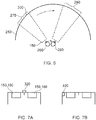
- Figure 6 schematically illustrates the effect of a user head movement in a VR or AR system.
- a virtual environment is represented by a (virtual) spherical shell 250 around a user. Because of the need to represent this arrangement on a two-dimensional paper drawing, the shell is represented by a part of a circle, at a distance from the user equivalent to the separation of the displayed virtual image from the user.
- a user is initially at a first position 260 and is directed towards a portion 270 of the virtual environment. It is this portion 270 which is represented in the images displayed on the display elements 150 of the user's HMD.
- the displayed portion of the virtual environment also moves so that, at the end of the movement, a new portion 290 is displayed by the HMD.
- the apparent viewpoint within the virtual environment moves with the head movement. If the head rotates to the right side, for example, as shown in Figure 6 , the apparent viewpoint also moves to the right from the user's point of view. If the situation is considered from the aspect of a displayed object, such as a displayed object 300, this will effectively move in the opposite direction to the head movement. So, if the head movement is to the right, the apparent viewpoint moves to the right but an object such as the displayed object 300 which is stationary in the virtual environment will move towards the left of the displayed image and eventually will disappear off the left-hand side of the displayed image, for the simple reason that the displayed portion of the virtual environment has moved to the right whereas the displayed object 300 has not moved in the virtual environment. Similar considerations apply to the up-down component of any motion.
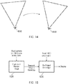
- FIGS 7a and 7b schematically illustrate HMDs with motion sensing.
- the two drawings are in a similar format to that shown in Figure 2 . That is to say, the drawings are schematic plan views of an HMD, in which the display element 150 and optical elements 160 are represented by a simple box shape. Many features of Figure 2 are not shown, for clarity of the diagrams. Both drawings show examples of HMDs with a motion detector for detecting motion of the observer's head.
- a forward-facing camera 320 is provided on the front of the HMD. This does not necessarily provide images for display to the user (although it could do so in an augmented reality arrangement). Instead, its primary purpose in the present embodiments is to allow motion sensing. A technique for using images captured by the camera 320 for motion sensing will be described below in connection with Figure 8 .
- the motion detector comprises a camera mounted so as to move with the frame; and an image comparator operable to compare successive images captured by the camera so as to detect inter-image motion.
- Figure 7b makes use of a hardware motion detector 330.
- This can be mounted anywhere within or on the HMD.
- suitable hardware motion detectors are piezoelectric accelerometers or optical fibre gyroscopes. It will of course be appreciated that both hardware motion detection and camera-based motion detection can be used in the same device, in which case one sensing arrangement could be used as a backup when the other one is unavailable, or one sensing arrangement (such as the camera) could provide data for changing the apparent viewpoint of the displayed images, whereas the other (such as an accelerometer) could provide data for image stabilisation.
- Figure 8 schematically illustrates one example of motion detection using the camera 320 of Figure 7a .
- the camera 320 is a video camera, capturing images at an image capture rate of, for example, 25 images per second. As each image is captured, it is passed to an image store 400 for storage and is also compared, by an image comparator 410, with a preceding image retrieved from the image store. The comparison uses known block matching techniques (so-called "optical flow” detection) to establish whether substantially the whole image captured by the camera 320 has moved since the time at which the preceding image was captured.
- Localised motion might indicate moving objects within the field of view of the camera 320, but global motion of substantially the whole image would tend to indicate motion of the camera rather than of individual features in the captured scene, and in the present case because the camera is mounted on the HMD, motion of the camera corresponds to motion of the HMD and in turn to motion of the user's head.
- the displacement between one image and the next, as detected by the image comparator 410, is converted to a signal indicative of motion by a motion detector 420. If required, the motion signal is converted by to a position signal by an integrator 430.
- the HMD can detect head motion using a mechanical or solid state detector 330 such as an accelerometer.
- a mechanical or solid state detector 330 such as an accelerometer.
- the detector 330 can be better suited for use with higher frequency motion detection.
- a high image rate camera such as a 200 Hz capture rate camera
- a camera-based system may be more appropriate.
- the detector 330 could take the place of the camera 320, the image store 400 and the comparator 410, so as to provide an input directly to the motion detector 420. Or the detector 330 could take the place of the motion detector 420 as well, directly providing an output signal indicative of physical motion.
- position or motion detecting techniques are of course possible.
- a mechanical arrangement by which the HMD is linked by a moveable pantograph arm to a fixed point may be used, with position and orientation sensors detecting changes in the deflection of the pantograph arm.
- a system of one or more transmitters and receivers, mounted on the HMD and on a fixed point can be used to allow detection of the position and orientation of the HMD by triangulation techniques.
- the HMD could carry one or more directional transmitters, and an array of receivers associated with known or fixed points could detect the relative signals from the one or more transmitters.
- the transmitters could be fixed and the receivers could be on the HMD.
- transmitters and receivers examples include infra-red transducers, ultrasonic transducers and radio frequency transducers.
- the radio frequency transducers could have a dual purpose, in that they could also form part of a radio frequency data link to and/or from the HMD, such as a Bluetooth® link.
- Figure 9 schematically illustrates image processing carried out in response to a detected position or change in position of the HMD, as technical background only to the processes to be described below.
- the apparent viewpoint of the video being displayed to the user of the HMD is changed in response to a change in actual position or orientation of the user's head.
- a motion sensor 450 (such as the arrangement of Figure 8 and/or the motion detector 330 of Figure 7b ) supplying data indicative of motion and/or current position to a required image position detector 460, which translates the actual position of the HMD into data defining the required image for display.
- An image generator 480 accesses image data stored in an image store 470 if required, and generates the required images from the appropriate viewpoint for display by the HMD.
- the external video signal source can provide the functionality of the image generator 480.
- the image generator 480 may act on the basis of metadata such as so-called view matrix data, in a manner to be described below.
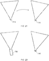
- Figure 10 schematically illustrates the capture of an image by a camera and Figure 11 schematically illustrates the re-projection of the captured image.
- a camera 500 captures an image of a portion 510 of a real-world scene.
- the field of view of the camera 500 is shown schematically as a generally triangular shape 520, such that the camera is at one apex of the generally triangular shape, the sides adjacent to the camera schematically indicate the left and right extremes of the field of view and the side opposite the camera schematically illustrates the portion of the scene which is captured.
- This schematic notation will be used in several of the following drawings.
- the view matrix may refer to the camera's position and/or orientation in space, either relative to a notional fixed point and orientation or expressed as changes with respect to the position and/or orientation applicable at a previous time (which may be the time associated with a preceding captured image, for example).
- the view matrix could be considered as the x, y and z spatial position of the camera along with its rotational orientation expressed as yaw, pitch and roll (general terms indicative of three orthogonal rotational degrees of freedom) and its viewing frustum (a general term indicative of the field of view of the camera, ranging between a wide-angle field of view and a narrow angle or telephoto field of view, and which may be expressed as an angular range corresponding to, for example, the angle 530 shown in Figure 10 ).
- the view matrix data need not comprise all of these data contributions. For example, in some arrangements, only a lateral rotational orientation (yaw) may be relevant.
- the choice of which data items to include within the view matrix data is therefore a matter for the system designer, taking into account the expected uses of the captured images and view matrix data.
- the view matrix data is stored in association with the captured image, for example as so-called metadata which is stored and/or transmitted as part of the overall image data package, for example by a camera apparatus such as that described below with reference to Figure 27 comprising an image capture device for capturing an image; a position and/or orientation detector for detecting the position and/or orientation of the camera apparatus at the time of capture of the image; and a metadata generator for associating metadata with the image, the metadata indicating the detected position and/or orientation of the camera apparatus at the time of capture of the image.
- a camera apparatus such as that described below with reference to Figure 27 comprising an image capture device for capturing an image; a position and/or orientation detector for detecting the position and/or orientation of the camera apparatus at the time of capture of the image; and a metadata generator for associating metadata with the image, the metadata indicating the detected position and/or orientation of the camera apparatus at the time of capture of the image.
- the camera 500 may be a stills camera or a video camera capturing a succession of images, separated by time intervals.
- Figure 11 schematically illustrates the re-projection of the image captured by the camera of Figure 10 according to a viewpoint of a viewer.
- the viewpoint 540 is schematically illustrated by an eye symbol and a generally triangular shape 550 which is similar to the triangular shape 520 discussed above.
- a process is carried out which relates the view matrix (as discussed above) of the viewpoint to the view matrix of the camera 500. Examples of such techniques will be described with reference to Figures 12 and 13 . Further examples are discussed in Seitz: "Image Based Transformation of Viewpoint and Scene Appearance", PhD Dissertation, Computer Sciences Department Technical Report 1354, University of Wisconsin - Madison, October 1997 .
- Figure 12 schematically illustrates an image rotation from a first view matrix 560 to a second view matrix 570.
- Re-projection of this type involves simply rotating and scaling the image so as to correct for any differences in field of view and orientation between the view matrix of the camera and the view matrix of the user viewpoint. Examples of this type of re-projection will be discussed below with reference to Figures 16 and 17 .
- Figure 13 schematically illustrates an image rotation and translation from a first view matrix 580 to eight second view matrix 590.
- the processing is slightly more involved, and may also use a depth map, indicating the image depth of different image features in the captured image, to allow the user viewpoint to be translated with respect to the viewpoint of the camera. Examples of the use of a depth map will be discussed below with reference to Figures 18-20 .
- Figure 14 schematically illustrates a latency issue with HMD image display.
- the position and/or orientation of an HMD can be used, for example as discussed with reference to Figure 9 , so that an image for display is rendered according to the detected position and/or orientation of the HMD.
- the arrangement discussed with reference to Figure 9 involves detecting the current position and/or orientation of the HMD and rendering an appropriate image for display.
- FIG 14 consider a situation in which the user's viewpoint is rotating (in a clockwise direction as illustrated schematically in Figure 14 ) from a first viewpoint 600 to a second viewpoint 610, over the course of a time interval of the order of an image repetition period of the image displays used in the HMD (for example, 1/25 second). Note that the two representations in Figure 14 are shown side-by-side, but this is for the purposes of the drawing rather than necessarily indicating a translation of the user viewpoint (although some translation could be involved between the two viewpoints).
- the position and/or orientation of the HMD is detected when the HMD is at the viewpoint 600.
- the next image for display is then rendered, but by the time that image is actually displayed, the viewpoint has rotated to the viewpoint 610.
- the result is that the image is displayed is incorrect for the user's viewpoint 610 at the time that image is displayed. This can provide a subjectively poorer experience for the user, and may possibly lead to disorientation or even nausea on the part of the user.
- Figure 15 is a schematic flow chart illustrating an image processing technique. The technique will first be discussed at a high level, and then more detail will be given below.
- the features of the technique shown in Figure 15 involve capturing or rendering an image (at a step of 620) according to the view matrix of the camera (in the case of a captured image) or the view matrix of the HMD (in the case of an image rendered by, for example, a computer game).
- the image would be rendered according to the view matrix corresponding to the viewpoint 600 in Figure 14 .
- the technique involves detecting an initial position and/or orientation of the viewer's head and generating an image for display according to the detected position and/or orientation.
- the image is then transmitted or passed to the HMD along with metadata defining that view matrix (that is to say, the view matrix according to which the image was captured or first rendered).
- the HMD view matrix is again detected (in other words, detecting a current position and/or orientation of the viewer's head at a time at which the image is to be displayed) and, at a step 630, the image is re-projected based on the metadata indicating the original view matrix and the view matrix detected from the HMD at the time of display (in the terminology of Figure 14 , this would be the view matrix corresponding to the viewpoint 610, so that the technique involves associating metadata with the generated image, the metadata indicating the initial position and/or orientation of the viewer's head). So, the technique involves re-projecting the generated image according to any differences between the initial position and/or orientation and the current position and/or orientation of the viewer's head and displaying the re-projected image using the display.
- the view matrix of the camera is generally not within the control of the display arrangements and so this technique provides a way of compensating for differences between the two view matrices.
- image rendering however, the issues are slightly different.
- a significant feature is that the time taken to process a re-projection operation can be much less than the time taken for a full rendering operation to generate an output image.
- the rendering operation takes place relative to a viewpoint (such as the viewpoint 600) which is correct at the time that the rendering operation is initiated, but the viewpoint is then adjusted (to the viewpoint 610, for example) at the time of display.
- a viewpoint such as the viewpoint 600
- the viewpoint is then adjusted (to the viewpoint 610, for example) at the time of display.
- the technique can involve receiving an image and associated metadata, detecting a current position and/or orientation of the viewer's head at a time at which the image is to be displayed, re-projecting the received image according to any differences between the position and/or orientation indicated by the metadata and the current position and/or orientation of the viewer's head, and displaying the re-projected image.
- the timing of the process can proceed as follows: At a time t 0 , the HMD view matrix data (representing the HMD's position at t 0 ) is detected. the step 620 is initiated and takes a period T render .
- the image is then transferred to the HMD. This can take a period of zero or more seconds (the period would be zero if, for example, the image had been rendered at the HMD). But in general, a period T delivery is noted for the time taken to deliver the image to the HMD ready for display.
- the HMD view matrix data is again detected. This could correspond to the required display time, in which case (according to the derivation below) the image would be displayed late by an amount T reproj , or it could be carried out at a time equal to a display time T display - T reproj . In either case it is carried out at a time dependent upon a required display time.
- the image is then re-projected (at the step 630) to account for differences between the initial and the latest view matrices.
- the time period taken for the re-projection is T reproj , assumed here to be much less than (or at least less than) T render .
- the image is then displayed at a time: t 0 + T render + T delivery + T reporoj .
- the detected initial position is detected at a latest time, allowing for the image generating latency and the image re-projection latency, to allow for the display of the re-projected image at the display time.
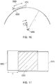
- Figure 16 schematically illustrates the rotation of an HMD viewpoint 650 in a clockwise direction.
- Figure 16 is similar to Figure 6 discussed above, in that the image for display is considered to lie on the surface of a sphere of radius r, where r is substantially equal to the distance from the user's eye to the virtual image generated by the HMD display system. Under this arrangement, a rotation of the viewpoint 650 by an angle ⁇ can be considered as a lateral movement on the surface of the sphere of radius r by a lateral distance d. Such a displacement d is schematically illustrated in Figure 17 . If it is assumed that an image generated at the step 620 is represented by an image 660 in Figure 16 , and an image generated at this step 630 is represented by an image 670 in Figure 16 , it may be seen that the two images may be represented side-by-side from the point of view of the user. (Note that in Figure 17 , a small vertical displacement is shown just to allow the different images to be distinguished from one another in the drawing).
- a "subtraction" operation is carried out, which is a schematic term to illustrate the operation of detecting the overlap between the required display position of the image 670 and the actual position of the image 660, so as to display within the image 670 the overlapping portion 680 (shaded in Figure 17 ) of the image 660.
- the re-projecting comprises detecting an overlapping portion between the generated image and the required re-projected image, and reproducing the overlapping portion as part of the re-projected image.
- the missing areas in the image 670 are masked or filled in using image data from a panoramic image captured or prepared for this purpose and stored by the display arrangement. So, embodiments of the technique therefore comprise filling portions of the re-projected image other than the overlapping portion with image material from a further image source.
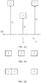
- Figure 18 schematically illustrates a depth map which may be derived, for example, from image data captured by a 3-D (binocular) camera or a so-called Z-camera, or which may be generated as part of the operation of a computer games machine's rendering engine.
- FIG. 18 In the schematic example of Figure 18 , three image objects labelled as objects A, B and C, are shown at respective image depths measured from an arbitrary depth position 700 of z A , z B and z C . Two potential viewpoints are shown, labelled as a viewpoint v 1 and a viewpoint v 2 respectively.
- Figures 19 and 20 schematically illustrate portions of images according to the viewpoint v 1 and the viewpoint v 2 respectively.
- the depth of each of the image objects is taken into account in generating the images.
- this technique can also be used at a re-projection stage such as that defined by the step 630 discussed above, so that image objects may be moved relative to one another in the re-projected image according to their respective image depths.
- the technique can involve providing depth data indicating the image depth of one or more image features, and the re-projecting can comprise repositioning one or more image features within the re-projected image according to the depth data.
- Figure 21 schematically illustrates a technique for image rendering and re-projection to compensate for HMD motion.
- a user viewpoint moves or rotates from a viewpoint 710, detected as part of the step 620 of Figure 15 , to a viewpoint 720 detected as part of the step 630 of Figure 15 and according to which the image for display is re-projected. In this way, an image according to the correct viewpoint 720 is displayed to the user.
- Figure 22 is a schematic flowchart relating to the technique shown in Figure 21 .
- process steps 800, 810, 820, 830, 840 and 850 are shown.
- the steps 800, 810 and 820 correspond generally to the step 620 of Figure 15 .
- the remaining steps 830, 840 and 850 correspond generally to the step 630 of Figure 15 .
- each of the steps in Figure 22 could be carried out immediately (or substantially immediately) in response to completion of the preceding step.
- the current position of the HMD (corresponding to the position 710 of Figure 21 ) is detected and, at the step 810, is stored (for example in a temporary working memory forming part of the HMD or the computer games machine).
- an image for display is rendered according to the viewpoint 710.
- the HMD position is again detected at the step 830 which, in this example, will detect the position 720.
- the image for display is re-projected as discussed above at the step 840 and is displayed to the user at the step 850.
- the timing of the steps could be in accordance with the example timings discussed above.
- Figure 23 schematically illustrates a technique for image capturing and re-projection to compensate for different camera and HMD positions.
- a camera viewpoint 730 is different to an HMD viewpoint 740.
- Figure 24 is a schematic flowchart relating to the technique shown in Figure 23 .
- process steps 900, 910, 920, 930, 940 and 950 are shown. Of these, the steps 900 and 910 correspond generally to the step 620 of Figure 15 . The remaining steps 920, 930, 940 and 950 correspond generally to the step 630 of Figure 15 .
- the current position of the camera (corresponding to the position 730 of Figure 23 ) is detected and, at the step 910, is transmitted as metadata along with the captured image.
- the HMD position is detected at the step 920 which, in this example, will detect the position 740.
- the image for display is re-projected as discussed above at the step 930 and is rendered (at the step 940) for display to the user at the step 950.
- Figure 25 schematically illustrates the viewing of a panoramic image 1030 formed by combining or stitching together images captured by respective cameras or camera positions 1000, 1010, 1020.
- This arrangement does not itself represent an embodiment of the present invention.
- real cameras do not have to be involved; the panoramic image could be formed by stitching together multiple computer-generated images having different respective viewpoints.
- the viewpoint of each of the cameras, camera positions or virtual cameras used to capture the panoramic image is associated with the panoramic image or the respective image portion corresponding to that viewpoint as image metadata, in a similar manner to the step 910 discussed above.
- an image 1050 for display is generated by re-projecting the respective image portions or the whole panoramic image according to the techniques discussed above.
- Figure 26 schematically illustrates camera viewpoint adjustment in a displayed image, which can allow images to be reproduced at their original size and position relative to the viewer. This arrangement does not itself represent an embodiment of the present invention.
- the left side of Figure 26 schematically illustrates a user capturing an image of (in this example) a tall building using a hand-held camera. As discussed above, the camera viewpoint is recorded and associated with the captured image as metadata.
- a user is doing the captured image by an HMD. The captured image is re-projected according to the user's viewpoint using the techniques discussed above.
- the data-processing operations described above may be carried out at the video signal source 80 (for example, a computer games machine) and/or the HMD (in terms of all of the steps of Figure 22 and the steps 920..950 of Figure 24 ).
- the division between processing at the HMD and processing at the source 80 is a matter for the system designer; it may be desirable to reduce the size, weight and power consumption of the HMD for user comfort, which would make it appropriate to move as much processing as possible to the source 80.
- some of the processing may take place entirely at the HMD. In either instance, the processing may be carried out by appropriate programmable hardware operating under software control, for example.
- Figure 27 schematically illustrates a camera 1100 having this functionality.
- the camera 1100 comprises a lens arrangement 1110, and image sensor 1120 arranged to receive light through the lens arrangement 1110 and convert the light into an image signal, a position, orientation and/or motion detector 1130, which may be of the types discussed above in connection with detecting the HMD's position, orientation and/or motion, and a processor 1140 operable to carry out at least the steps 900, 910 using data from the detector 1130 and to output an image signal 1150 having associated viewpoint metadata as discussed above. Note that if optical flow motion detection is used as described earlier, the image data for this process may be simply derived from the sensor 1120, so avoiding the need for a separate detector 1130.
- FIG 28 schematically illustrates a viewer 1200 observing a display screen 1210.
- the display screen 1210 may be a forward-projection screen (in which case one or more projectors, not shown, may be positioned on the same side of the screen 1210 as the user), or a rear-projection screen (in which case one or more projectors, not shown, may be positioned on the other side of the screen to that of the user) or formed as one or more display panels such as liquid crystal display (LCD) panels.
- LCD liquid crystal display
- the same techniques as discussed above can be used in respect of a larger display 1210 and a detection of the user's head orientation.
- Various ways in which the head orientation can be detected will be discussed below.
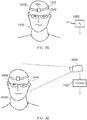
- Figure 29 schematically illustrates a user 1300 wearing a head orientation detector 1310.
- the head orientation detector 1310 is illustrated schematically as a headband 1320 and an orientation detector 1330 mounted on the headband.
- the arrangement could be made more discreet, for example been combined into a fitment attachable to a conventional pair of spectacles 1340 or forming part of a hat or pair of headphones.
- the orientation detector 1330 operates according to the techniques shown in Figure 8 if all the various alternatives discussed earlier in connection with the description of Figure 8 .
- the orientation detector 1330 encompasses much of the functionality of an HMD, but without the image display function.
- the orientation detector 1330 may comprise a processor to derive an orientation from whichever data source it is using (for example, images of the ambient scene or accelerometer data), so that the orientation detector 1330 transmits data indicative of the orientation to a receiver 1350, for example by a wireless link such as a Bluetooth link. Of course, a wired link could be used instead.
- the orientation detector 1330 may transmit "raw" acquired data, such as captured images of the surroundings or raw data from an accelerometer to the receiver 1350, so that the receiver 1350 (or a further downstream processing device, not shown) derives orientation information from the raw data received from the orientation detector 1330.
- Figure 30 schematically illustrates a passive head orientation detection technique.
- a video camera 1410 captures images of the user 1400 and passes the images to a processor 1420.
- the processor 1420 can operate in various ways.
- the processor 1420 can apply known face-detection techniques to detect the orientation of the user's face with respect to the camera 1410. For example, such techniques may involve comparing an image portion containing the user's face (normalised to a standard scale) to various Eigen images each indicative of characteristics of a face at a different orientation relative to the camera. The closest match amongst the Eigen images may be taken to be indicative of the current orientation of the user's face.
- the processor 1420 may be calibrated with information defining the relative orientation of the camera 1410 and the display screen in use, so as to be able to provide an output which is indicative of a current orientation of the user's face relative to the display screen.
- the user may wear one or more passive markers such as a reflective or retro reflective marker (not shown in Figure 30 ) to assist the processor 1420 in the detection of the orientation of the user's face relative to the camera.
- a reflective or retro reflective marker (not shown in Figure 30 ) to assist the processor 1420 in the detection of the orientation of the user's face relative to the camera.
- the camera 1410 may comprise a source of illumination arranged to eliminate the markers.
- the illumination may be invisible or substantially invisible to the user, for example infrared illumination.
Description
- This disclosure relates to displays.
- As background, an example head-mountable display (HMD) will be discussed, although (as described further below) the disclosure is applicable to other types of displays.
- An HMD is an image or video display device which may be worn on the head or as part of a helmet. Either one eye or both eyes are provided with small electronic display devices.
- Some HMDs allow a displayed image to be superimposed on a real-world view. This type of HMD can be referred to as an optical see-through HMD and generally requires the display devices to be positioned somewhere other than directly in front of the user's eyes. Some way of deflecting the displayed image so that the user may see it is then required. This might be through the use of a partially reflective mirror placed in front of the user's eyes so as to allow the user to see through the mirror but also to see a reflection of the output of the display devices. In another arrangement, disclosed in
EP-A-1 731 943 andUS-A-2010/0157433 , a waveguide arrangement employing total internal reflection is used to convey a displayed image from a display device disposed to the side of the user's head so that the user may see the displayed image but still see a view of the real world through the waveguide. Once again, in either of these types of arrangement, a virtual image of the display is created (using known techniques) so that the user sees the virtual image at an appropriate size and distance to allow relaxed viewing. For example, even though the physical display device may be tiny (for example, 10 mm x 10 mm) and may be just a few millimetres from the user's eye, the virtual image may be arranged so as to be perceived by the user at a distance of (for example) 20 m from the user, having a perceived size of 5 m x 5m. - Other HMDs, however, allow the user only to see the displayed images, which is to say that they obscure the real world environment surrounding the user. This type of HMD can position the actual display devices in front of the user's eyes, in association with appropriate lenses which place a virtual displayed image at a suitable distance for the user to focus in a relaxed manner - for example, at a similar virtual distance and perceived size as the optical see-through HMD described above. This type of device might be used for viewing movies or similar recorded content, or for viewing so-called virtual reality content representing a virtual space surrounding the user. It is of course however possible to display a real-world view on this type of HMD, for example by using a forward-facing camera to generate images for display on the display devices.
- Although the original development of HMDs was perhaps driven by the military and professional applications of these devices, HMDs are becoming more popular for use by casual users in, for example, computer game or domestic computing applications.
- Previously proposed arrangements are disclosed by
US 2007/273610 A1 ,US 2001/010546 A1 ,KR 101 180 119 B1 WO 2013/125921 A1 ),EP 2 211 224 A1 ,EP 0 709 816 A2 andUS 2005/156817 A1 . - The present disclosure is defined by the appended claims.
- A technical description will now be provided with reference to the accompanying drawings, in which:
-
Figure 1 schematically illustrates an HMD worn by a user; -
Figure 2 is a schematic plan view of an HMD; -
Figure 3 schematically illustrates the formation of a virtual image by an HMD; -
Figure 4 schematically illustrates another type of display for use in an HMD; -
Figure 5 schematically illustrates a pair of stereoscopic images; -
Figure 6 schematically illustrates a change of view of user of an HMD; -
Figures 7a and 7b schematically illustrate HMDs with motion sensing; -
Figure 8 schematically illustrates a position sensor based on optical flow detection; -
Figure 9 schematically illustrates the generation of images in response to HMD position or motion detection; -
Figure 10 schematically illustrates the capture of an image by a camera; -
Figure 11 schematically illustrates the re-projection of the captured image; -
Figure 12 schematically illustrates an image rotation; -
Figure 13 schematically illustrates an image rotation and translation; -
Figure 14 schematically illustrates a latency issue with HMD image display; -
Figure 15 is a schematic flow chart illustrating an image processing technique; -
Figure 16 schematically illustrates the rotation of an HMD; -
Figure 17 schematically illustrates image position subtraction; -
Figure 18 schematically illustrates a depth map; -
Figures 19 and 20 schematically illustrate images according to different respective viewpoints; -
Figure 21 schematically illustrates a technique for image rendering and re-projection to compensate for HMD motion; -
Figure 22 is a schematic flowchart relating to the technique shown inFigure 21 ; -
Figure 23 schematically illustrates a technique for image capture and re-projection to compensate for different camera and HMD positions; -
Figure 24 is a schematic flowchart relating to the technique shown inFigure 23 ; -
Figure 25 schematically illustrates the viewing of a panoramic image; -
Figure 26 schematically illustrates camera viewpoint adjustment in a displayed image; -
Figure 27 schematically illustrates a camera apparatus; -
Figure 28 schematically illustrates a viewer observing a display screen; -
Figure 29 schematically illustrates a user wearing a head orientation detector; and -
Figure 30 schematically illustrates a passive head orientation detection technique. - Embodiments of the present disclosure provide a display method and apparatus using a display operable to display an image to a viewer. In some embodiments, the display is a head-mountable display and the position and/or orientation of the viewer's head is detected by detecting a position and/or orientation of the head-mountable display. The head mountable display may have a frame to be mounted onto an viewer's head, the frame defining one or two eye display positions which, in use, are positioned in front of a respective eye of the viewer and a respective display element is mounted with respect to each of the eye display positions, the display element providing a virtual image of a video display of a video signal from a video signal source to that eye of the viewer. In other examples, the display is not a head-mountable display. In some embodiments, the display (whether head mountable or not) may be referred to as an immersive display, in that in normal use it fills at least a threshold angular range (for example, at least 40°) of the field of view of the user. Examples include multiple projector displays, wrap-around (curved) displays and the like.
- Referring now to
Figure 1 , auser 10 is wearing anHMD 20 on the user'shead 30. The HMD comprises aframe 40, in this example formed of a rear strap and a top strap, and adisplay portion 50. - The HMD of
Figure 1 completely obscures the user's view of the surrounding environment. All that the user can see is the pair of images displayed within the HMD. - The HMD has associated
headphone earpieces 60 which fit into the user's left andright ears 70. Theearpieces 60 replay an audio signal provided from an external source, which may be the same as the video signal source which provides the video signal for display to the user's eyes. - In operation, a video signal is provided for display by the HMD. This could be provided by an external video signal source 80 such as a video games machine or data processing apparatus (such as a personal computer), in which case the signals could be transmitted to the HMD by a wired or a wireless connection. Examples of suitable wireless connections include Bluetooth (R) connections. Audio signals for the
earpieces 60 can be carried by the same connection. Similarly, any control signals passed from the HMD to the video (audio) signal source may be carried by the same connection. - Accordingly, the arrangement of
Figure 1 provides an example of a head-mountable display system comprising a frame to be mounted onto an observer's head, the frame defining one or two eye display positions which, in use, are positioned in front of a respective eye of the observer and a display element mounted with respect to each of the eye display positions, the display element providing a virtual image of a video display of a video signal from a video signal source to that eye of the observer. -
Figure 1 shows just one example of an HMD. Other formats are possible: for example an HMD could use a frame more similar to that associated with conventional eyeglasses, namely a substantially horizontal leg extending back from the display portion to the top rear of the user's ear, possibly curling down behind the ear. In other examples, the user's view of the external environment may not in fact be entirely obscured; the displayed images could be arranged so as to be superposed (from the user's point of view) over the external environment. An example of such an arrangement will be described below with reference toFigure 4 . - In the example of
Figure 1 , a separate respective display is provided for each of the user's eyes. A schematic plan view of how this is achieved is provided asFigure 2 , which illustrates thepositions 100 of the user's eyes and therelative position 110 of the user's nose. Thedisplay portion 50, in schematic form, comprises anexterior shield 120 to mask ambient light from the user's eyes and aninternal shield 130 which prevents one eye from seeing the display intended for the other eye. The combination of the user's face, theexterior shield 120 and theinterior shield 130 form twocompartments 140, one for each eye. In each of the compartments there is provided adisplay element 150 and one or moreoptical elements 160. The way in which the display element and the optical element(s) cooperate to provide a display to the user will be described with reference toFigure 3 . - Referring to
Figure 3 , thedisplay element 150 generates a displayed image which is (in this example) refracted by the optical elements 160 (shown schematically as a convex lens but which could include compound lenses or other elements) so as to generate avirtual image 170 which appears to the user to be larger than and significantly further away than the real image generated by thedisplay element 150. As an example, the virtual image may have an apparent image size (image diagonal) of more than 1 m and may be disposed at a distance of more than 1 m from the user's eye (or from the frame of the HMD). In general terms, depending on the purpose of the HMD, it is desirable to have the virtual image disposed a significant distance from the user. For example, if the HMD is for viewing movies or the like, it is desirable that the user's eyes are relaxed during such viewing, which requires a distance (to the virtual image) of at least several metres. InFigure 3 , solid lines (such as the line 180) are used to denote real optical rays, whereas broken lines (such as the line 190) are used to denote virtual rays. - An alternative arrangement is shown in
Figure 4 . This arrangement may be used where it is desired that the user's view of the external environment is not entirely obscured. However, it is also applicable to HMDs in which the user's external view is wholly obscured. In the arrangement ofFigure 4 , thedisplay element 150 andoptical elements 200 cooperate to provide an image which is projected onto amirror 210, which deflects the image towards the user'seye position 220. The user perceives a virtual image to be located at aposition 230 which is in front of the user and at a suitable distance from the user. - In the case of an HMD in which the user's view of the external surroundings is entirely obscured, the
mirror 210 can be a substantially 100% reflective mirror. The arrangement ofFigure 4 then has the advantage that the display element and optical elements can be located closer to the centre of gravity of the user's head and to the side of the user's eyes, which can produce a less bulky HMD for the user to wear. Alternatively, if the HMD is designed not to completely obscure the user's view of the external environment, themirror 210 can be made partially reflective so that the user sees the external environment, through themirror 210, with the virtual image superposed over the real external environment. - In the case where separate respective displays are provided for each of the user's eyes, it is possible to display stereoscopic images. An example of a pair of stereoscopic images for display to the left and right eyes is shown in
Figure 5 . The images exhibit a lateral displacement relative to one another, with the displacement of image features depending upon the (real or simulated) lateral separation of the cameras by which the images were captured, the angular convergence of the cameras and the (real or simulated) distance of each image feature from the camera position. - Note that the lateral displacements in
Figure 5 (and those inFigure 15 to be described below) could in fact be the other way round, which is to say that the left eye image as drawn could in fact be the right eye image, and the right eye image as drawn could in fact be the left eye image. This is because some stereoscopic displays tend to shift objects to the right in the right eye image and to the left in the left eye image, so as to simulate the idea that the user is looking through a stereoscopic window onto the scene beyond. However, some HMDs use the arrangement shown inFigure 5 because this gives the impression to the user that the user is viewing the scene through a pair of binoculars. The choice between these two arrangements is at the discretion of the system designer, - In some situations (not themselves representing use according to an embodiment of the claimed invention), an HMD may be used simply to view movies and the like. In this case, there is no change required to the apparent viewpoint of the displayed images as the user turns the user's head, for example from side to side. In other uses, however, such as those associated with virtual reality (VR) or augmented reality (AR) systems, the user's viewpoint need to track movements with respect to a real or virtual space in which the user is located.
- This tracking is carried out by detecting motion of the HMD and varying the apparent viewpoint of the displayed images so that the apparent viewpoint tracks the motion.
-
Figure 6 schematically illustrates the effect of a user head movement in a VR or AR system. - Referring to
Figure 6 , a virtual environment is represented by a (virtual)spherical shell 250 around a user. Because of the need to represent this arrangement on a two-dimensional paper drawing, the shell is represented by a part of a circle, at a distance from the user equivalent to the separation of the displayed virtual image from the user. A user is initially at afirst position 260 and is directed towards aportion 270 of the virtual environment. It is thisportion 270 which is represented in the images displayed on thedisplay elements 150 of the user's HMD. - Consider the situation in which the user then moves his head to a new position and/or
orientation 280. In order to maintain the correct sense of the virtual reality or augmented reality display, the displayed portion of the virtual environment also moves so that, at the end of the movement, anew portion 290 is displayed by the HMD. - So, in this arrangement, the apparent viewpoint within the virtual environment moves with the head movement. If the head rotates to the right side, for example, as shown in
Figure 6 , the apparent viewpoint also moves to the right from the user's point of view. If the situation is considered from the aspect of a displayed object, such as a displayedobject 300, this will effectively move in the opposite direction to the head movement. So, if the head movement is to the right, the apparent viewpoint moves to the right but an object such as the displayedobject 300 which is stationary in the virtual environment will move towards the left of the displayed image and eventually will disappear off the left-hand side of the displayed image, for the simple reason that the displayed portion of the virtual environment has moved to the right whereas the displayedobject 300 has not moved in the virtual environment. Similar considerations apply to the up-down component of any motion. -
Figures 7a and 7b schematically illustrate HMDs with motion sensing. The two drawings are in a similar format to that shown inFigure 2 . That is to say, the drawings are schematic plan views of an HMD, in which thedisplay element 150 andoptical elements 160 are represented by a simple box shape. Many features ofFigure 2 are not shown, for clarity of the diagrams. Both drawings show examples of HMDs with a motion detector for detecting motion of the observer's head. - In
Figure 7a , a forward-facingcamera 320 is provided on the front of the HMD. This does not necessarily provide images for display to the user (although it could do so in an augmented reality arrangement). Instead, its primary purpose in the present embodiments is to allow motion sensing. A technique for using images captured by thecamera 320 for motion sensing will be described below in connection withFigure 8 . In these arrangements, the motion detector comprises a camera mounted so as to move with the frame; and an image comparator operable to compare successive images captured by the camera so as to detect inter-image motion. -
Figure 7b makes use of ahardware motion detector 330. This can be mounted anywhere within or on the HMD. Examples of suitable hardware motion detectors are piezoelectric accelerometers or optical fibre gyroscopes. It will of course be appreciated that both hardware motion detection and camera-based motion detection can be used in the same device, in which case one sensing arrangement could be used as a backup when the other one is unavailable, or one sensing arrangement (such as the camera) could provide data for changing the apparent viewpoint of the displayed images, whereas the other (such as an accelerometer) could provide data for image stabilisation. -
Figure 8 schematically illustrates one example of motion detection using thecamera 320 ofFigure 7a . - The
camera 320 is a video camera, capturing images at an image capture rate of, for example, 25 images per second. As each image is captured, it is passed to animage store 400 for storage and is also compared, by animage comparator 410, with a preceding image retrieved from the image store. The comparison uses known block matching techniques (so-called "optical flow" detection) to establish whether substantially the whole image captured by thecamera 320 has moved since the time at which the preceding image was captured. Localised motion might indicate moving objects within the field of view of thecamera 320, but global motion of substantially the whole image would tend to indicate motion of the camera rather than of individual features in the captured scene, and in the present case because the camera is mounted on the HMD, motion of the camera corresponds to motion of the HMD and in turn to motion of the user's head. - The displacement between one image and the next, as detected by the
image comparator 410, is converted to a signal indicative of motion by amotion detector 420. If required, the motion signal is converted by to a position signal by anintegrator 430. - As mentioned above, as an alternative to, or in addition to, the detection of motion by detecting inter-image motion between images captured by a video camera associated with the HMD, the HMD can detect head motion using a mechanical or
solid state detector 330 such as an accelerometer. This can in fact give a faster response in respect of the indication of motion, given that the response time of the video-based system is at best the reciprocal of the image capture rate. In some instances, therefore, thedetector 330 can be better suited for use with higher frequency motion detection. However, in other instances, for example if a high image rate camera is used (such as a 200 Hz capture rate camera), a camera-based system may be more appropriate. In terms ofFigure 8 , thedetector 330 could take the place of thecamera 320, theimage store 400 and thecomparator 410, so as to provide an input directly to themotion detector 420. Or thedetector 330 could take the place of themotion detector 420 as well, directly providing an output signal indicative of physical motion. - Other position or motion detecting techniques are of course possible. For example, a mechanical arrangement by which the HMD is linked by a moveable pantograph arm to a fixed point (for example, on a data processing device or on a piece of furniture) may be used, with position and orientation sensors detecting changes in the deflection of the pantograph arm. In other embodiments, a system of one or more transmitters and receivers, mounted on the HMD and on a fixed point, can be used to allow detection of the position and orientation of the HMD by triangulation techniques. For example, the HMD could carry one or more directional transmitters, and an array of receivers associated with known or fixed points could detect the relative signals from the one or more transmitters. Or the transmitters could be fixed and the receivers could be on the HMD. Examples of transmitters and receivers include infra-red transducers, ultrasonic transducers and radio frequency transducers. The radio frequency transducers could have a dual purpose, in that they could also form part of a radio frequency data link to and/or from the HMD, such as a Bluetooth® link.
-
Figure 9 schematically illustrates image processing carried out in response to a detected position or change in position of the HMD, as technical background only to the processes to be described below. - As mentioned above in connection with
Figure 6 , in some applications such as virtual reality and augmented reality arrangements, the apparent viewpoint of the video being displayed to the user of the HMD is changed in response to a change in actual position or orientation of the user's head. - With reference to
Figure 9 , this is achieved by a motion sensor 450 (such as the arrangement ofFigure 8 and/or themotion detector 330 ofFigure 7b ) supplying data indicative of motion and/or current position to a requiredimage position detector 460, which translates the actual position of the HMD into data defining the required image for display. Animage generator 480 accesses image data stored in animage store 470 if required, and generates the required images from the appropriate viewpoint for display by the HMD. The external video signal source can provide the functionality of theimage generator 480. - The
image generator 480 may act on the basis of metadata such as so-called view matrix data, in a manner to be described below. - In order to illustrate schematically some of the general concepts associated with the present technology,
Figure 10 schematically illustrates the capture of an image by a camera andFigure 11 schematically illustrates the re-projection of the captured image. - Referring to
Figure 10 , acamera 500 captures an image of aportion 510 of a real-world scene. The field of view of thecamera 500 is shown schematically as a generallytriangular shape 520, such that the camera is at one apex of the generally triangular shape, the sides adjacent to the camera schematically indicate the left and right extremes of the field of view and the side opposite the camera schematically illustrates the portion of the scene which is captured. This schematic notation will be used in several of the following drawings. - To discuss the general concept of image re-projection, assume that in the arrangement of
Figure 10 , not only the image is captured but also information defining a "view matrix" of the camera is also captured. Here, the view matrix may refer to the camera's position and/or orientation in space, either relative to a notional fixed point and orientation or expressed as changes with respect to the position and/or orientation applicable at a previous time (which may be the time associated with a preceding captured image, for example). So, in one expression, the view matrix could be considered as the x, y and z spatial position of the camera along with its rotational orientation expressed as yaw, pitch and roll (general terms indicative of three orthogonal rotational degrees of freedom) and its viewing frustum (a general term indicative of the field of view of the camera, ranging between a wide-angle field of view and a narrow angle or telephoto field of view, and which may be expressed as an angular range corresponding to, for example, theangle 530 shown inFigure 10 ). The view matrix data need not comprise all of these data contributions. For example, in some arrangements, only a lateral rotational orientation (yaw) may be relevant. The choice of which data items to include within the view matrix data is therefore a matter for the system designer, taking into account the expected uses of the captured images and view matrix data. - The view matrix data is stored in association with the captured image, for example as so-called metadata which is stored and/or transmitted as part of the overall image data package, for example by a camera apparatus such as that described below with reference to
Figure 27 comprising an image capture device for capturing an image; a position and/or orientation detector for detecting the position and/or orientation of the camera apparatus at the time of capture of the image; and a metadata generator for associating metadata with the image, the metadata indicating the detected position and/or orientation of the camera apparatus at the time of capture of the image. - Note that the
camera 500 may be a stills camera or a video camera capturing a succession of images, separated by time intervals. -
Figure 11 schematically illustrates the re-projection of the image captured by the camera ofFigure 10 according to a viewpoint of a viewer. Theviewpoint 540 is schematically illustrated by an eye symbol and a generallytriangular shape 550 which is similar to thetriangular shape 520 discussed above. In order to display the image captured by thecamera 500 so that it is appropriate for viewing according to the viewpoint shown inFigure 11 , a process is carried out which relates the view matrix (as discussed above) of the viewpoint to the view matrix of thecamera 500. Examples of such techniques will be described with reference toFigures 12 and 13 . Further examples are discussed in Seitz: "Image Based Transformation of Viewpoint and Scene Appearance", PhD Dissertation, Computer Sciences Department Technical Report 1354, University of Wisconsin - Madison, October 1997. -
Figure 12 schematically illustrates an image rotation from afirst view matrix 560 to asecond view matrix 570. Re-projection of this type involves simply rotating and scaling the image so as to correct for any differences in field of view and orientation between the view matrix of the camera and the view matrix of the user viewpoint. Examples of this type of re-projection will be discussed below with reference toFigures 16 and 17 . -
Figure 13 schematically illustrates an image rotation and translation from afirst view matrix 580 to eightsecond view matrix 590. Here, the processing is slightly more involved, and may also use a depth map, indicating the image depth of different image features in the captured image, to allow the user viewpoint to be translated with respect to the viewpoint of the camera. Examples of the use of a depth map will be discussed below with reference toFigures 18-20 . - Note that the images do not have to be camera-captured images. These techniques are all equally applicable to machine-generated images such as images generated by a computer games machine for displayed to the user as part of the process of playing a computer game.
-
Figure 14 schematically illustrates a latency issue with HMD image display. As discussed above, the position and/or orientation of an HMD can be used, for example as discussed with reference toFigure 9 , so that an image for display is rendered according to the detected position and/or orientation of the HMD. In the case of viewing a portion of a wider captured image, or generating a required image as part of computer game play, the arrangement discussed with reference toFigure 9 involves detecting the current position and/or orientation of the HMD and rendering an appropriate image for display. - However, the latency involved in this process can lead to an incorrect image being generated.
- Referring to
Figure 14 , consider a situation in which the user's viewpoint is rotating (in a clockwise direction as illustrated schematically inFigure 14 ) from afirst viewpoint 600 to asecond viewpoint 610, over the course of a time interval of the order of an image repetition period of the image displays used in the HMD (for example, 1/25 second). Note that the two representations inFigure 14 are shown side-by-side, but this is for the purposes of the drawing rather than necessarily indicating a translation of the user viewpoint (although some translation could be involved between the two viewpoints). - In order to allow time for the next output image to be rendered, the position and/or orientation of the HMD is detected when the HMD is at the
viewpoint 600. The next image for display is then rendered, but by the time that image is actually displayed, the viewpoint has rotated to theviewpoint 610. The result is that the image is displayed is incorrect for the user'sviewpoint 610 at the time that image is displayed. This can provide a subjectively poorer experience for the user, and may possibly lead to disorientation or even nausea on the part of the user. - Techniques which address this problem will now be discussed.
-
Figure 15 is a schematic flow chart illustrating an image processing technique. The technique will first be discussed at a high level, and then more detail will be given below. - The features of the technique shown in
Figure 15 involve capturing or rendering an image (at a step of 620) according to the view matrix of the camera (in the case of a captured image) or the view matrix of the HMD (in the case of an image rendered by, for example, a computer game). - In the latter example, the image would be rendered according to the view matrix corresponding to the
viewpoint 600 inFigure 14 . In other words, the technique involves detecting an initial position and/or orientation of the viewer's head and generating an image for display according to the detected position and/or orientation. The image is then transmitted or passed to the HMD along with metadata defining that view matrix (that is to say, the view matrix according to which the image was captured or first rendered). At the time of display, the HMD view matrix is again detected (in other words, detecting a current position and/or orientation of the viewer's head at a time at which the image is to be displayed) and, at astep 630, the image is re-projected based on the metadata indicating the original view matrix and the view matrix detected from the HMD at the time of display (in the terminology ofFigure 14 , this would be the view matrix corresponding to theviewpoint 610, so that the technique involves associating metadata with the generated image, the metadata indicating the initial position and/or orientation of the viewer's head). So, the technique involves re-projecting the generated image according to any differences between the initial position and/or orientation and the current position and/or orientation of the viewer's head and displaying the re-projected image using the display. - In the case of a captured image, the view matrix of the camera is generally not within the control of the display arrangements and so this technique provides a way of compensating for differences between the two view matrices. In the case of image rendering, however, the issues are slightly different. However, a significant feature is that the time taken to process a re-projection operation can be much less than the time taken for a full rendering operation to generate an output image. In turn, this means that the rendering operation has to start earlier relative to the time of display which can lead to the latency problems with regards to detection of the appropriate viewpoint to use for the rendering operation, as discussed with reference to
Figure 14 . By contrast, using the technique described with reference toFigure 15 , the rendering operation takes place relative to a viewpoint (such as the viewpoint 600) which is correct at the time that the rendering operation is initiated, but the viewpoint is then adjusted (to theviewpoint 610, for example) at the time of display. This avoids the need to try to predict theviewpoint 610 in advance, which could also lead to errors in the viewpoint, but provides an image for displayed to the user at the appropriate viewpoint corresponding to the display time. Accordingly, the technique can involve receiving an image and associated metadata, detecting a current position and/or orientation of the viewer's head at a time at which the image is to be displayed, re-projecting the received image according to any differences between the position and/or orientation indicated by the metadata and the current position and/or orientation of the viewer's head, and displaying the re-projected image. - In examples consistent with the claimed invention, the timing of the process can proceed as follows:
At a time t0, the HMD view matrix data (representing the HMD's position at t0) is detected. thestep 620 is initiated and takes a period Trender. - At a time t0 + Trender, the required image has been rendered.
- The image is then transferred to the HMD. This can take a period of zero or more seconds (the period would be zero if, for example, the image had been rendered at the HMD). But in general, a period Tdelivery is noted for the time taken to deliver the image to the HMD ready for display.
- At a time t0 + Trender + Tdelivery, the HMD view matrix data is again detected. This could correspond to the required display time, in which case (according to the derivation below) the image would be displayed late by an amount Treproj, or it could be carried out at a time equal to a display time Tdisplay - Treproj. In either case it is carried out at a time dependent upon a required display time.
- The image is then re-projected (at the step 630) to account for differences between the initial and the latest view matrices. The time period taken for the re-projection is Treproj, assumed here to be much less than (or at least less than) Trender.
- The image is then displayed at a time:

- Therefore, when the image is displayed, its maximum positional error corresponds to the movement of the HMD in the period Treproj, whereas without the present technique, the maximum positional error corresponds to the movement of the HMD in the larger period Trender+ Tdelivery.
- These are therefore examples of a generating step taking a period of time equal to at least an image generating latency, and a re-projecting step taking a period of time equal to at least an image re-projection latency, the image generating latency being longer than the image re-projection latency.
- In the above examples, the detected initial position is detected at a latest time, allowing for the image generating latency and the image re-projection latency, to allow for the display of the re-projected image at the display time.
- Worked examples of this technique will be discussed below.
-
Figure 16 schematically illustrates the rotation of anHMD viewpoint 650 in a clockwise direction. -
Figure 16 is similar toFigure 6 discussed above, in that the image for display is considered to lie on the surface of a sphere of radius r, where r is substantially equal to the distance from the user's eye to the virtual image generated by the HMD display system. Under this arrangement, a rotation of theviewpoint 650 by an angle θ can be considered as a lateral movement on the surface of the sphere of radius r by a lateral distance d. Such a displacement d is schematically illustrated inFigure 17 . If it is assumed that an image generated at thestep 620 is represented by animage 660 inFigure 16 , and an image generated at thisstep 630 is represented by animage 670 inFigure 16 , it may be seen that the two images may be represented side-by-side from the point of view of the user. (Note that inFigure 17 , a small vertical displacement is shown just to allow the different images to be distinguished from one another in the drawing). - In a simple example, in order to generate (at the step 630) an
appropriate image 670 for display to the user, a "subtraction" operation is carried out, which is a schematic term to illustrate the operation of detecting the overlap between the required display position of theimage 670 and the actual position of theimage 660, so as to display within theimage 670 the overlapping portion 680 (shaded inFigure 17 ) of theimage 660. In other words, the re-projecting comprises detecting an overlapping portion between the generated image and the required re-projected image, and reproducing the overlapping portion as part of the re-projected image. - In embodiments of the present disclosure, the missing areas in the image 670 (those parts not shown as shaded) are masked or filled in using image data from a panoramic image captured or prepared for this purpose and stored by the display arrangement. So, embodiments of the technique therefore comprise filling portions of the re-projected image other than the overlapping portion with image material from a further image source.
- In order to re-project images by taking into account translations of the viewpoint, embodiments of the disclosure can use that information associated with the images.
Figure 18 schematically illustrates a depth map which may be derived, for example, from image data captured by a 3-D (binocular) camera or a so-called Z-camera, or which may be generated as part of the operation of a computer games machine's rendering engine. - In the schematic example of
Figure 18 , three image objects labelled as objects A, B and C, are shown at respective image depths measured from anarbitrary depth position 700 of zA, zB and zC. Two potential viewpoints are shown, labelled as a viewpoint v1 and a viewpoint v2 respectively. -
Figures 19 and 20 schematically illustrate portions of images according to the viewpoint v1 and the viewpoint v2 respectively. At a rendering stage, the depth of each of the image objects is taken into account in generating the images. However, this technique can also be used at a re-projection stage such as that defined by thestep 630 discussed above, so that image objects may be moved relative to one another in the re-projected image according to their respective image depths. Accordingly, the technique can involve providing depth data indicating the image depth of one or more image features, and the re-projecting can comprise repositioning one or more image features within the re-projected image according to the depth data. -
Figure 21 schematically illustrates a technique for image rendering and re-projection to compensate for HMD motion. In a similar manner toFigure 14 , a user viewpoint moves or rotates from aviewpoint 710, detected as part of thestep 620 ofFigure 15 , to aviewpoint 720 detected as part of thestep 630 ofFigure 15 and according to which the image for display is re-projected. In this way, an image according to thecorrect viewpoint 720 is displayed to the user. - In more detail,
Figure 22 is a schematic flowchart relating to the technique shown inFigure 21 . InFigure 22 , process steps 800, 810, 820, 830, 840 and 850 are shown. Of these, thesteps step 620 ofFigure 15 . The remainingsteps step 630 ofFigure 15 . Note that in some examples, each of the steps inFigure 22 could be carried out immediately (or substantially immediately) in response to completion of the preceding step. - At the
step 800, the current position of the HMD (corresponding to theposition 710 ofFigure 21 ) is detected and, at thestep 810, is stored (for example in a temporary working memory forming part of the HMD or the computer games machine). At thestep 820, an image for display is rendered according to theviewpoint 710. - At the time at which the rendered image is to be displayed, or at a time interval t before the instant at which the image is to be displayed, where t is the length of time required for the re-projection operation, the HMD position is again detected at the
step 830 which, in this example, will detect theposition 720. The image for display is re-projected as discussed above at thestep 840 and is displayed to the user at thestep 850. - The timing of the steps could be in accordance with the example timings discussed above.
- A similar arrangement, not itself forming an embodiment of the present invention, relating to captured images will now be discussed.
Figure 23 schematically illustrates a technique for image capturing and re-projection to compensate for different camera and HMD positions. InFigure 23 acamera viewpoint 730 is different to anHMD viewpoint 740. -
Figure 24 is a schematic flowchart relating to the technique shown inFigure 23 . - In
Figure 24 , process steps 900, 910, 920, 930, 940 and 950 are shown. Of these, thesteps step 620 ofFigure 15 . The remainingsteps step 630 ofFigure 15 . - At the
step 900, the current position of the camera (corresponding to theposition 730 ofFigure 23 ) is detected and, at thestep 910, is transmitted as metadata along with the captured image. - At the time at which the image is to be displayed, or at a time interval t before the instant at which the image is to be displayed, where t is the length of time required for the re-projection operation, the HMD position is detected at the
step 920 which, in this example, will detect theposition 740. The image for display is re-projected as discussed above at thestep 930 and is rendered (at the step 940) for display to the user at thestep 950. -
Figure 25 schematically illustrates the viewing of apanoramic image 1030 formed by combining or stitching together images captured by respective cameras orcamera positions step 910 discussed above. At the time of display, according to auser viewpoint 1040, animage 1050 for display is generated by re-projecting the respective image portions or the whole panoramic image according to the techniques discussed above. -
Figure 26 schematically illustrates camera viewpoint adjustment in a displayed image, which can allow images to be reproduced at their original size and position relative to the viewer. This arrangement does not itself represent an embodiment of the present invention. The left side ofFigure 26 schematically illustrates a user capturing an image of (in this example) a tall building using a hand-held camera. As discussed above, the camera viewpoint is recorded and associated with the captured image as metadata. To the right ofFigures 26 , a user is doing the captured image by an HMD. The captured image is re-projected according to the user's viewpoint using the techniques discussed above. - The data-processing operations described above may be carried out at the video signal source 80 (for example, a computer games machine) and/or the HMD (in terms of all of the steps of
Figure 22 and thesteps 920..950 ofFigure 24 ). The division between processing at the HMD and processing at the source 80 is a matter for the system designer; it may be desirable to reduce the size, weight and power consumption of the HMD for user comfort, which would make it appropriate to move as much processing as possible to the source 80. Alternatively, in order to reduce the amount of data which needs to be transferred between the HMD and the source 80, some of the processing may take place entirely at the HMD. In either instance, the processing may be carried out by appropriate programmable hardware operating under software control, for example. Thesteps Figure 24 may be carried out by a camera or (in a similar manner to the discussion above) by apparatus associated with a camera. For the purposes of example (though not relating to an embodiment of the present invention),Figure 27 schematically illustrates acamera 1100 having this functionality. InFigure 27 , thecamera 1100 comprises alens arrangement 1110, andimage sensor 1120 arranged to receive light through thelens arrangement 1110 and convert the light into an image signal, a position, orientation and/ormotion detector 1130, which may be of the types discussed above in connection with detecting the HMD's position, orientation and/or motion, and aprocessor 1140 operable to carry out at least thesteps detector 1130 and to output animage signal 1150 having associated viewpoint metadata as discussed above. Note that if optical flow motion detection is used as described earlier, the image data for this process may be simply derived from thesensor 1120, so avoiding the need for aseparate detector 1130. - The embodiments described so far have related primarily to head mountable displays. Further arrangements will now be described in which the display or displays are not head mountable.
-
Figure 28 schematically illustrates aviewer 1200 observing adisplay screen 1210. Thedisplay screen 1210 may be a forward-projection screen (in which case one or more projectors, not shown, may be positioned on the same side of thescreen 1210 as the user), or a rear-projection screen (in which case one or more projectors, not shown, may be positioned on the other side of the screen to that of the user) or formed as one or more display panels such as liquid crystal display (LCD) panels. The skilled person will understand that the particular technology used to implement the display of images on thedisplay screen 1210 is not material to the present embodiments. - Many of the techniques discussed above in connection with HMD devices can also be used equivalently in respect of the arrangement of
Figure 28 . In the earlier discussion of HMD systems, the orientation of the HMD was detected by various techniques. A similar consideration in the arrangement ofFigure 28 involves the detection of the user's head orientation. It will be appreciated that the head orientation does not necessarily indicate the direction that the user is looking, but it is generally considered to indicate a good approximation of the direction ofviewing 1220. - So, in some embodiments, the same techniques as discussed above (in connection with HMD systems) can be used in respect of a
larger display 1210 and a detection of the user's head orientation. Various ways in which the head orientation can be detected will be discussed below. -
Figure 29 schematically illustrates auser 1300 wearing ahead orientation detector 1310. Thehead orientation detector 1310 is illustrated schematically as aheadband 1320 and anorientation detector 1330 mounted on the headband. In practice, the arrangement could be made more discreet, for example been combined into a fitment attachable to a conventional pair ofspectacles 1340 or forming part of a hat or pair of headphones. - Functionally, the
orientation detector 1330 operates according to the techniques shown inFigure 8 if all the various alternatives discussed earlier in connection with the description ofFigure 8 . In this regard, theorientation detector 1330 encompasses much of the functionality of an HMD, but without the image display function. - The
orientation detector 1330 may comprise a processor to derive an orientation from whichever data source it is using (for example, images of the ambient scene or accelerometer data), so that theorientation detector 1330 transmits data indicative of the orientation to areceiver 1350, for example by a wireless link such as a Bluetooth link. Of course, a wired link could be used instead. Alternatively, theorientation detector 1330 may transmit "raw" acquired data, such as captured images of the surroundings or raw data from an accelerometer to thereceiver 1350, so that the receiver 1350 (or a further downstream processing device, not shown) derives orientation information from the raw data received from theorientation detector 1330. -
Figure 30 schematically illustrates a passive head orientation detection technique. This arrangement does not necessarily require the user in 1400 to wear or carry any particular equipment or items. Avideo camera 1410 captures images of theuser 1400 and passes the images to aprocessor 1420. Theprocessor 1420 can operate in various ways. In one example, theprocessor 1420 can apply known face-detection techniques to detect the orientation of the user's face with respect to thecamera 1410. For example, such techniques may involve comparing an image portion containing the user's face (normalised to a standard scale) to various Eigen images each indicative of characteristics of a face at a different orientation relative to the camera. The closest match amongst the Eigen images may be taken to be indicative of the current orientation of the user's face. Theprocessor 1420 may be calibrated with information defining the relative orientation of thecamera 1410 and the display screen in use, so as to be able to provide an output which is indicative of a current orientation of the user's face relative to the display screen. - In another example, the user may wear one or more passive markers such as a reflective or retro reflective marker (not shown in
Figure 30 ) to assist theprocessor 1420 in the detection of the orientation of the user's face relative to the camera. For example, if theside arms 1430 of the user's spectacles were provided with different (that is to say, distinguishable by the camera 1410) reflective markers, the relative size in the captured image of the respective markers could be processed to provide an indication of the orientation of the user's face. Optionally, thecamera 1410 may comprise a source of illumination arranged to eliminate the markers. Optionally, the illumination may be invisible or substantially invisible to the user, for example infrared illumination. - The techniques described above may be implemented in hardware, software or combinations of the two. In the case that a software-controlled data processing apparatus is employed to implement one or more features of the embodiments, it will be appreciated that such software is also considered as an embodiment of the disclosure.
Claims (12)
- A display method using a display operable to display an image to a viewer, the method comprising:detecting (800) an initial position and/or orientation of the viewer's head;generating (820), by a video signal source, an image, hereafter referred to as a generated image, for display according to the detected initial position and/or orientation;detecting (830) a current position and/or orientation of the viewer's head depending upon a display time at which the image is to be displayed;re-projecting (840), by an image re-projector, the generated image according to any differences between the initial position and/or orientation and the current position and/or orientation of the viewer's head, in which the step of re-projecting comprises detecting an overlapping portion between the generated image and the required re-projected image, and reproducing the overlapping portion as part of the re-projected image;storing a panoramic image to provide a further image source to fill portions of the re-projected image other than the overlapping portion, the panoramic image having been captured or prepared for this purpose;filling portions of the re-projected image other than the overlapping portion with image material from the further image source; anddisplaying (850) the re-projected image using the display, in which the generating step comprises associating metadata with the generated image, the metadata indicating the initial position and/or orientation of the viewer's head.
- A method according to any one of the preceding claims, in which the generating step comprises providing depth data indicating the image depth of one or more image features, and the step of re-projecting comprises repositioning one or more image features within the re-projected image according to the depth data.
- A method according to any one of the preceding claims, in which the display is a head-mountable display and the position and/or orientation of the viewer's head is detected by detecting a position and/or orientation of the head-mountable display.
- A method according to any one of the preceding claims, in which the generating step takes a period of time equal to at least an image generating latency, and the re-projecting step takes a period of time equal to at least an image re-projection latency, the image generating latency being longer than the image re-projection latency.
- A method according to claim 4, in which the detected initial position is detected at a latest time, allowing for the image generating latency and the image re-projection latency, to allow for the display of the re-projected image at the display time.
- Computer software for carrying out a method according to any one of the preceding claims.
- A display system comprising:a display element (150) observable by a viewer;a position and/or orientation detector (450, 420) for detecting position and/or orientation of the viewer's head;a video signal source (620) for generating an image, hereafter referred to as a generated image, for display according to an initial position and/or orientation of the viewer's head;an image re-projector (630) for receiving the generated image and re-projecting the generated image for display by the display element according to any differences between the position and/or orientation applicable to the generation of the image and the current position and/or orientation of the viewer's head, in which the image re-projector is configured to detect an overlapping portion between the generated image and the required re-projected image;a store for storing a panoramic image to provide a further image source to fill portions of the re-projected image other than the overlapping portion, the panoramic image having been captured or prepared for this purpose;in which the image re-projector (630) is configured to reproduce the overlapping portion as part of the re-projected image and to fill portions of the re-projected image other than the overlapping portion with image material from the further image source, in which the video signal source is configured to associate metadata with the generated image, the metadata indicating the initial position and/or orientation of the viewer's head.
- A system according to claim 7, in which the video signal source is a video gaming or data processing machine.
- A system according to claim 7 or claim 8, in which the position and/or orientation detector comprises:a camera (320) mounted so as to move with the user's head; andan image comparator (410) operable to compare successive images captured by the camera so as to detect inter-image motion.
- A system according to claim 7 or claim 8, in which the position and/or orientation detector comprises an accelerometer (450).
- A system according to claim 7 or claim 8, in which the display element forms part of a head-mountable display (10) having a frame (40) to be mounted onto an viewer's head, the frame defining one or two eye display positions which, in use, are positioned in front of a respective eye of the viewer and a respective display element is mounted with respect to each of the eye display positions, the display element providing a virtual image of a video display of a video signal from a video signal source to that eye of the viewer.
- A system according to claim 11, in which, in use, the virtual image is generated at a distance of more than one metre from the frame.
Priority Applications (1)
| Application Number | Priority Date | Filing Date | Title |
|---|---|---|---|
| EP21211371.6A EP4012482A1 (en) | 2013-03-25 | 2014-03-24 | Display |
Applications Claiming Priority (4)
| Application Number | Priority Date | Filing Date | Title |
|---|---|---|---|
| GBGB1305402.8A GB201305402D0 (en) | 2013-03-25 | 2013-03-25 | Head mountable display |
| GB1308151.8A GB2512404A (en) | 2013-03-25 | 2013-05-07 | Display |
| GB1404739.3A GB2514466B (en) | 2013-03-25 | 2014-03-17 | Display |
| PCT/GB2014/050905 WO2014155072A2 (en) | 2013-03-25 | 2014-03-24 | Display |
Related Child Applications (1)
| Application Number | Title | Priority Date | Filing Date |
|---|---|---|---|
| EP21211371.6A Division EP4012482A1 (en) | 2013-03-25 | 2014-03-24 | Display |
Publications (2)
| Publication Number | Publication Date |
|---|---|
| EP2979127A2 EP2979127A2 (en) | 2016-02-03 |
| EP2979127B1 true EP2979127B1 (en) | 2021-12-01 |
Family
ID=48326595
Family Applications (2)
| Application Number | Title | Priority Date | Filing Date |
|---|---|---|---|
| EP21211371.6A Pending EP4012482A1 (en) | 2013-03-25 | 2014-03-24 | Display |
| EP14715401.7A Active EP2979127B1 (en) | 2013-03-25 | 2014-03-24 | Display method and system |
Family Applications Before (1)
| Application Number | Title | Priority Date | Filing Date |
|---|---|---|---|
| EP21211371.6A Pending EP4012482A1 (en) | 2013-03-25 | 2014-03-24 | Display |
Country Status (5)
| Country | Link |
|---|---|
| US (1) | US10054796B2 (en) |
| EP (2) | EP4012482A1 (en) |
| CN (1) | CN105103034B (en) |
| GB (3) | GB201305402D0 (en) |
| WO (1) | WO2014155072A2 (en) |
Families Citing this family (67)
| Publication number | Priority date | Publication date | Assignee | Title |
|---|---|---|---|---|
| GB201310359D0 (en) * | 2013-06-11 | 2013-07-24 | Sony Comp Entertainment Europe | Head-Mountable apparatus and systems |
| US20150228119A1 (en) | 2014-02-11 | 2015-08-13 | Osterhout Group, Inc. | Spatial location presentation in head worn computing |
| US9766463B2 (en) | 2014-01-21 | 2017-09-19 | Osterhout Group, Inc. | See-through computer display systems |
| US9753288B2 (en) | 2014-01-21 | 2017-09-05 | Osterhout Group, Inc. | See-through computer display systems |
| US9852545B2 (en) | 2014-02-11 | 2017-12-26 | Osterhout Group, Inc. | Spatial location presentation in head worn computing |
| US20160187651A1 (en) | 2014-03-28 | 2016-06-30 | Osterhout Group, Inc. | Safety for a vehicle operator with an hmd |
| GB2528699B (en) | 2014-07-29 | 2017-05-03 | Sony Computer Entertainment Europe Ltd | Image processing |
| US20160037134A1 (en) * | 2014-07-31 | 2016-02-04 | Todd MEDEMA | Methods and systems of simulating time of day and environment of remote locations |
| US9686520B2 (en) * | 2015-01-22 | 2017-06-20 | Microsoft Technology Licensing, Llc | Reconstructing viewport upon user viewpoint misprediction |
| US10127714B1 (en) * | 2015-01-27 | 2018-11-13 | Google Llc | Spherical three-dimensional video rendering for virtual reality |
| GB2534921B (en) * | 2015-02-06 | 2021-11-17 | Sony Interactive Entertainment Inc | Head-mountable display system |
| US10878775B2 (en) | 2015-02-17 | 2020-12-29 | Mentor Acquisition One, Llc | See-through computer display systems |
| US20160239985A1 (en) | 2015-02-17 | 2016-08-18 | Osterhout Group, Inc. | See-through computer display systems |
| JP6540108B2 (en) * | 2015-03-09 | 2019-07-10 | 富士通株式会社 | Image generation method, system, device, and terminal |
| US10419655B2 (en) | 2015-04-27 | 2019-09-17 | Snap-Aid Patents Ltd. | Estimating and using relative head pose and camera field-of-view |
| US11252399B2 (en) | 2015-05-28 | 2022-02-15 | Microsoft Technology Licensing, Llc | Determining inter-pupillary distance |
| US9746675B2 (en) | 2015-05-28 | 2017-08-29 | Microsoft Technology Licensing, Llc | Alignment based view matrix tuning |
| US9658686B2 (en) | 2015-05-28 | 2017-05-23 | Microsoft Technology Licensing, Llc | Motion based view matrix tuning |
| KR101716326B1 (en) * | 2015-09-08 | 2017-03-14 | 클릭트 주식회사 | Method and program for transmitting and playing virtual reality image |
| KR102501752B1 (en) | 2015-09-21 | 2023-02-20 | 삼성전자주식회사 | The method and apparatus for comppensating motion of the head mounted display |
| CN107111371B (en) * | 2015-09-30 | 2019-12-06 | 华为技术有限公司 | method, device and terminal for displaying panoramic visual content |
| JP6548821B2 (en) * | 2015-09-30 | 2019-07-24 | 株式会社ソニー・インタラクティブエンタテインメント | How to optimize the placement of content on the screen of a head mounted display |
| GB2543320B (en) * | 2015-10-14 | 2020-05-13 | Sony Interactive Entertainment Inc | Head-mountable display system |
| US9781342B1 (en) * | 2015-10-22 | 2017-10-03 | Gopro, Inc. | System and method for identifying comment clusters for panoramic content segments |
| ES2935067T3 (en) * | 2015-11-10 | 2023-03-01 | Thales Defense & Security Inc | Robust vision-inertial pedestrian tracking with heading autoalignment |
| CN105915877A (en) * | 2015-12-27 | 2016-08-31 | 乐视致新电子科技(天津)有限公司 | Free film watching method and device of three-dimensional video |
| WO2017120906A1 (en) * | 2016-01-15 | 2017-07-20 | 赵政荣 | Patent information notification method for use during playing game and head-mounted virtual reality apparatus |
| US10317991B2 (en) | 2016-02-09 | 2019-06-11 | Google Llc | Pixel adjusting at display controller for electronic display stabilization |
| US10591728B2 (en) | 2016-03-02 | 2020-03-17 | Mentor Acquisition One, Llc | Optical systems for head-worn computers |
| US10667981B2 (en) | 2016-02-29 | 2020-06-02 | Mentor Acquisition One, Llc | Reading assistance system for visually impaired |
| CN105955454A (en) * | 2016-04-15 | 2016-09-21 | 北京小鸟看看科技有限公司 | Anti-vertigo method and device for virtual reality system |
| CN105892683A (en) * | 2016-04-29 | 2016-08-24 | 上海乐相科技有限公司 | Display method and target equipment |
| US11182930B2 (en) * | 2016-05-02 | 2021-11-23 | Waves Audio Ltd. | Head tracking with adaptive reference |
| SE540058C2 (en) * | 2016-05-10 | 2018-03-06 | Bae Systems Haegglunds Ab | Method and system for facilitating transportation of an observer in a vehicle |
| JP2017208688A (en) * | 2016-05-18 | 2017-11-24 | 株式会社スクウェア・エニックス | Program, computer device, program execution method, and computer system |
| US20190335164A1 (en) * | 2016-06-21 | 2019-10-31 | Philips Lighting Holding B.V. | Display system and method |
| CN106170082A (en) * | 2016-06-30 | 2016-11-30 | 深圳市虚拟现实科技有限公司 | The remotely real-time comprehensive transmission of panoramic picture and display packing |
| CN106131647B (en) * | 2016-07-18 | 2019-03-19 | 杭州当虹科技有限公司 | A kind of more pictures based on virtual reality video viewing method simultaneously |
| CN106094210A (en) * | 2016-08-05 | 2016-11-09 | 江苏艾锐泰克无人飞行器科技有限公司 | A kind of mobile phone large-size screen monitors presentation device and system of taking photo by plane |
| JP6228640B1 (en) * | 2016-08-17 | 2017-11-08 | 株式会社コロプラ | Display control method and program for causing a computer to execute the display control method |
| CN106331823B (en) * | 2016-08-31 | 2019-08-20 | 北京奇艺世纪科技有限公司 | A kind of video broadcasting method and device |
| CN106445129A (en) * | 2016-09-14 | 2017-02-22 | 乐视控股(北京)有限公司 | Method, device and system for displaying panoramic picture information |
| KR102630681B1 (en) * | 2016-10-11 | 2024-01-30 | 삼성전자주식회사 | Display apparatus and method for generating capture image |
| CN106782260B (en) * | 2016-12-06 | 2020-05-29 | 歌尔科技有限公司 | Display method and device for virtual reality motion scene |
| GB2558280A (en) * | 2016-12-23 | 2018-07-11 | Sony Interactive Entertainment Inc | Head mountable display system |
| US9992461B1 (en) * | 2017-02-08 | 2018-06-05 | Hyundai Motor Company | Projection orientation correction system for vehicle |
| KR101874111B1 (en) | 2017-03-03 | 2018-07-03 | 클릭트 주식회사 | Method and program for playing virtual reality image |
| EP3595787A1 (en) * | 2017-03-13 | 2020-01-22 | Holodia AG | Method for generating multimedia data associated with a system for practicing sports |
| CN106970467B (en) * | 2017-03-28 | 2020-03-24 | 联想(北京)有限公司 | Information display method and head-mounted display equipment |
| US11258999B2 (en) | 2017-05-18 | 2022-02-22 | Samsung Electronics Co., Ltd. | Method and device for reducing motion sickness when providing 360-degree video |
| JP2019079193A (en) * | 2017-10-23 | 2019-05-23 | キヤノン株式会社 | Information processor, imaging device, program and imaging system |
| US11119331B2 (en) * | 2018-03-28 | 2021-09-14 | Disney Enterprises, Inc. | Method for dampening projector vibration |
| US10520739B1 (en) * | 2018-07-11 | 2019-12-31 | Valve Corporation | Dynamic panel masking |
| CN111354088B (en) * | 2018-12-21 | 2023-11-10 | 宏达国际电子股份有限公司 | Environment map building method and system |
| CN112148115A (en) * | 2019-06-28 | 2020-12-29 | 中兴通讯股份有限公司 | Media processing method, device, system and readable storage medium |
| GB2585198B (en) | 2019-07-01 | 2022-03-02 | Sony Interactive Entertainment Inc | Method and device for generating video frames |
| WO2021101844A1 (en) | 2019-11-18 | 2021-05-27 | Magic Leap, Inc. | Mapping and localization of a passable world |
| US11150470B2 (en) * | 2020-01-07 | 2021-10-19 | Microsoft Technology Licensing, Llc | Inertial measurement unit signal based image reprojection |
| EP4097711A4 (en) | 2020-01-27 | 2024-01-24 | Magic Leap Inc | Augmented reality map curation |
| US11860439B1 (en) | 2020-05-06 | 2024-01-02 | Apple Inc. | Head-mounted electronic device with alignment sensors |
| US20220201271A1 (en) * | 2020-12-23 | 2022-06-23 | Facebook Technologies, Llc | Temporal foveated rendering |
| US11622100B2 (en) * | 2021-02-17 | 2023-04-04 | flexxCOACH VR | 360-degree virtual-reality system for dynamic events |
| US11715257B2 (en) | 2021-05-14 | 2023-08-01 | Zoox, Inc. | Simulation view generation based on simulated sensor operations |
| US11430177B1 (en) * | 2021-05-14 | 2022-08-30 | Zoox, Inc. | Mapping simulated sensors to simulated environment views |
| US11741661B2 (en) | 2021-05-14 | 2023-08-29 | Zoox, Inc. | Sensor simulation with unified multi-sensor views |
| US11544896B2 (en) | 2021-05-14 | 2023-01-03 | Zoox, Inc. | Spatial and temporal upsampling techniques for simulated sensor data |
| WO2023069422A1 (en) * | 2021-10-20 | 2023-04-27 | Nantstudios, Llc | Camera tracking via dynamic perspectives |
Citations (3)
| Publication number | Priority date | Publication date | Assignee | Title |
|---|---|---|---|---|
| EP0709816A2 (en) * | 1994-10-28 | 1996-05-01 | Canon Kabushiki Kaisha | Display apparatus and its control method |
| US20050156817A1 (en) * | 2002-08-30 | 2005-07-21 | Olympus Corporation | Head-mounted display system and method for processing images |
| EP2211224A1 (en) * | 2009-01-27 | 2010-07-28 | Thomson Licensing SA | Head-mounted display and operating method thereof |
Family Cites Families (27)
| Publication number | Priority date | Publication date | Assignee | Title |
|---|---|---|---|---|
| NL8301864A (en) * | 1983-05-26 | 1984-12-17 | Philips Nv | MAIN TV OR EQUIPMENT FOR INDIVIDUAL DISPLAY OF IMAGES. |
| US5566073A (en) | 1994-07-11 | 1996-10-15 | Margolin; Jed | Pilot aid using a synthetic environment |
| US5742264A (en) | 1995-01-24 | 1998-04-21 | Matsushita Electric Industrial Co., Ltd. | Head-mounted display |
| US6552744B2 (en) * | 1997-09-26 | 2003-04-22 | Roxio, Inc. | Virtual reality camera |
| CA2385548C (en) * | 1999-09-22 | 2010-09-21 | Canadian Space Agency | Method and system for time/motion compensation for head mounted displays |
| US7312766B1 (en) * | 2000-09-22 | 2007-12-25 | Canadian Space Agency | Method and system for time/motion compensation for head mounted displays |
| JP3620537B2 (en) * | 2003-05-02 | 2005-02-16 | セイコーエプソン株式会社 | Image processing system, projector, program, information storage medium, and image processing method |
| CN100416336C (en) * | 2003-06-12 | 2008-09-03 | 美国西门子医疗解决公司 | Calibrating real and virtual views |
| US7418170B2 (en) | 2004-03-29 | 2008-08-26 | Sony Corporation | Optical device and virtual image display device |
| US7259758B2 (en) * | 2004-06-21 | 2007-08-21 | Microsoft Corporation | System and method for reducing latency in display of computer-generated graphics |
| US9323055B2 (en) * | 2006-05-26 | 2016-04-26 | Exelis, Inc. | System and method to display maintenance and operational instructions of an apparatus using augmented reality |
| CN201145773Y (en) * | 2008-01-24 | 2008-11-05 | 寇开泰 | Glasses type displayer |
| JP4674634B2 (en) | 2008-12-19 | 2011-04-20 | ソニー株式会社 | Head-mounted display |
| US20100156907A1 (en) * | 2008-12-23 | 2010-06-24 | Microsoft Corporation | Display surface tracking |
| US20100309295A1 (en) * | 2009-06-04 | 2010-12-09 | Chow Kenny W Y | 3d video processor integrated with head mounted display |
| US9366862B2 (en) * | 2010-02-28 | 2016-06-14 | Microsoft Technology Licensing, Llc | System and method for delivering content to a group of see-through near eye display eyepieces |
| US20120188148A1 (en) * | 2011-01-24 | 2012-07-26 | Microvision, Inc. | Head Mounted Meta-Display System |
| JP5960796B2 (en) * | 2011-03-29 | 2016-08-02 | クアルコム,インコーポレイテッド | Modular mobile connected pico projector for local multi-user collaboration |
| US8836771B2 (en) * | 2011-04-26 | 2014-09-16 | Echostar Technologies L.L.C. | Apparatus, systems and methods for shared viewing experience using head mounted displays |
| WO2012166593A2 (en) * | 2011-05-27 | 2012-12-06 | Thomas Seidl | System and method for creating a navigable, panoramic three-dimensional virtual reality environment having ultra-wide field of view |
| US20140176609A1 (en) * | 2011-08-09 | 2014-06-26 | Pioneer Corporation | Mixed reality apparatus |
| GB201116566D0 (en) * | 2011-09-26 | 2011-11-09 | Skype Ltd | Video stabilisation |
| US9087471B2 (en) * | 2011-11-04 | 2015-07-21 | Google Inc. | Adaptive brightness control of head mounted display |
| US20130135303A1 (en) * | 2011-11-28 | 2013-05-30 | Cast Group Of Companies Inc. | System and Method for Visualizing a Virtual Environment Online |
| KR101180119B1 (en) | 2012-02-23 | 2012-09-05 | (주)올라웍스 | Method, apparatusand computer-readable recording medium for controlling display by head trackting using camera module |
| US10269179B2 (en) * | 2012-10-05 | 2019-04-23 | Elwha Llc | Displaying second augmentations that are based on registered first augmentations |
| US20140240469A1 (en) * | 2013-02-28 | 2014-08-28 | Motorola Mobility Llc | Electronic Device with Multiview Image Capture and Depth Sensing |
-
2013
- 2013-03-25 GB GBGB1305402.8A patent/GB201305402D0/en not_active Ceased
- 2013-05-07 GB GB1308151.8A patent/GB2512404A/en not_active Withdrawn
-
2014
- 2014-03-17 GB GB1404739.3A patent/GB2514466B/en active Active
- 2014-03-24 EP EP21211371.6A patent/EP4012482A1/en active Pending
- 2014-03-24 US US14/778,867 patent/US10054796B2/en active Active
- 2014-03-24 CN CN201480016970.9A patent/CN105103034B/en active Active
- 2014-03-24 EP EP14715401.7A patent/EP2979127B1/en active Active
- 2014-03-24 WO PCT/GB2014/050905 patent/WO2014155072A2/en active Application Filing
Patent Citations (3)
| Publication number | Priority date | Publication date | Assignee | Title |
|---|---|---|---|---|
| EP0709816A2 (en) * | 1994-10-28 | 1996-05-01 | Canon Kabushiki Kaisha | Display apparatus and its control method |
| US20050156817A1 (en) * | 2002-08-30 | 2005-07-21 | Olympus Corporation | Head-mounted display system and method for processing images |
| EP2211224A1 (en) * | 2009-01-27 | 2010-07-28 | Thomson Licensing SA | Head-mounted display and operating method thereof |
Also Published As
| Publication number | Publication date |
|---|---|
| EP4012482A1 (en) | 2022-06-15 |
| CN105103034A (en) | 2015-11-25 |
| CN105103034B (en) | 2019-11-12 |
| GB2514466B (en) | 2017-11-29 |
| GB201308151D0 (en) | 2013-06-12 |
| EP2979127A2 (en) | 2016-02-03 |
| GB201305402D0 (en) | 2013-05-08 |
| GB2514466A (en) | 2014-11-26 |
| GB2512404A (en) | 2014-10-01 |
| WO2014155072A2 (en) | 2014-10-02 |
| US10054796B2 (en) | 2018-08-21 |
| GB201404739D0 (en) | 2014-04-30 |
| WO2014155072A3 (en) | 2014-11-20 |
| US20160246061A1 (en) | 2016-08-25 |
Similar Documents
| Publication | Publication Date | Title |
|---|---|---|
| EP2979127B1 (en) | Display method and system | |
| EP3051525B1 (en) | Display | |
| US10257492B2 (en) | Image encoding and display | |
| US10306202B2 (en) | Image encoding and display | |
| EP3008691B1 (en) | Head-mountable apparatus and systems | |
| EP3070513B1 (en) | Head-mountable display system | |
| EP3008548B1 (en) | Head-mountable apparatus and systems | |
| GB2517057A (en) | Head-mountable apparatus and systems | |
| US9372346B2 (en) | Directional light beams for angle detection | |
| EP4207067A1 (en) | Apparatus and method for virtual reality | |
| GB2558283A (en) | Image processing | |
| WO2018115842A1 (en) | Head mounted virtual reality display | |
| WO2018115843A1 (en) | Head mountable display system |
Legal Events
| Date | Code | Title | Description |
|---|---|---|---|
| PUAI | Public reference made under article 153(3) epc to a published international application that has entered the european phase |
Free format text: ORIGINAL CODE: 0009012 |
|
| 17P | Request for examination filed |
Effective date: 20150829 |
|
| AK | Designated contracting states |
Kind code of ref document: A2 Designated state(s): AL AT BE BG CH CY CZ DE DK EE ES FI FR GB GR HR HU IE IS IT LI LT LU LV MC MK MT NL NO PL PT RO RS SE SI SK SM TR |
|
| AX | Request for extension of the european patent |
Extension state: BA ME |
|
| DAX | Request for extension of the european patent (deleted) | ||
| RAP1 | Party data changed (applicant data changed or rights of an application transferred) |
Owner name: SONY INTERACTIVE ENTERTAINMENT EUROPE LIMITED |
|
| STAA | Information on the status of an ep patent application or granted ep patent |
Free format text: STATUS: EXAMINATION IS IN PROGRESS |
|
| 17Q | First examination report despatched |
Effective date: 20190611 |
|
| STAA | Information on the status of an ep patent application or granted ep patent |
Free format text: STATUS: EXAMINATION IS IN PROGRESS |
|
| RAP1 | Party data changed (applicant data changed or rights of an application transferred) |
Owner name: SONY INTERACTIVE ENTERTAINMENT INC. |
|
| GRAP | Despatch of communication of intention to grant a patent |
Free format text: ORIGINAL CODE: EPIDOSNIGR1 |
|
| STAA | Information on the status of an ep patent application or granted ep patent |
Free format text: STATUS: GRANT OF PATENT IS INTENDED |
|
| INTG | Intention to grant announced |
Effective date: 20210628 |
|
| GRAS | Grant fee paid |
Free format text: ORIGINAL CODE: EPIDOSNIGR3 |
|
| GRAA | (expected) grant |
Free format text: ORIGINAL CODE: 0009210 |
|
| STAA | Information on the status of an ep patent application or granted ep patent |
Free format text: STATUS: THE PATENT HAS BEEN GRANTED |
|
| AK | Designated contracting states |
Kind code of ref document: B1 Designated state(s): AL AT BE BG CH CY CZ DE DK EE ES FI FR GB GR HR HU IE IS IT LI LT LU LV MC MK MT NL NO PL PT RO RS SE SI SK SM TR |
|
| REG | Reference to a national code |
Ref country code: GB Ref legal event code: FG4D |
|
| REG | Reference to a national code |
Ref country code: AT Ref legal event code: REF Ref document number: 1452328 Country of ref document: AT Kind code of ref document: T Effective date: 20211215 Ref country code: CH Ref legal event code: EP |
|
| REG | Reference to a national code |
Ref country code: IE Ref legal event code: FG4D |
|
| REG | Reference to a national code |
Ref country code: DE Ref legal event code: R096 Ref document number: 602014081495 Country of ref document: DE |
|
| REG | Reference to a national code |
Ref country code: NL Ref legal event code: FP |
|
| REG | Reference to a national code |
Ref country code: LT Ref legal event code: MG9D |
|
| REG | Reference to a national code |
Ref country code: AT Ref legal event code: MK05 Ref document number: 1452328 Country of ref document: AT Kind code of ref document: T Effective date: 20211201 |
|
| PG25 | Lapsed in a contracting state [announced via postgrant information from national office to epo] |
Ref country code: RS Free format text: LAPSE BECAUSE OF FAILURE TO SUBMIT A TRANSLATION OF THE DESCRIPTION OR TO PAY THE FEE WITHIN THE PRESCRIBED TIME-LIMIT Effective date: 20211201 Ref country code: LT Free format text: LAPSE BECAUSE OF FAILURE TO SUBMIT A TRANSLATION OF THE DESCRIPTION OR TO PAY THE FEE WITHIN THE PRESCRIBED TIME-LIMIT Effective date: 20211201 Ref country code: FI Free format text: LAPSE BECAUSE OF FAILURE TO SUBMIT A TRANSLATION OF THE DESCRIPTION OR TO PAY THE FEE WITHIN THE PRESCRIBED TIME-LIMIT Effective date: 20211201 Ref country code: BG Free format text: LAPSE BECAUSE OF FAILURE TO SUBMIT A TRANSLATION OF THE DESCRIPTION OR TO PAY THE FEE WITHIN THE PRESCRIBED TIME-LIMIT Effective date: 20220301 Ref country code: AT Free format text: LAPSE BECAUSE OF FAILURE TO SUBMIT A TRANSLATION OF THE DESCRIPTION OR TO PAY THE FEE WITHIN THE PRESCRIBED TIME-LIMIT Effective date: 20211201 |
|
| PG25 | Lapsed in a contracting state [announced via postgrant information from national office to epo] |
Ref country code: SE Free format text: LAPSE BECAUSE OF FAILURE TO SUBMIT A TRANSLATION OF THE DESCRIPTION OR TO PAY THE FEE WITHIN THE PRESCRIBED TIME-LIMIT Effective date: 20211201 Ref country code: PL Free format text: LAPSE BECAUSE OF FAILURE TO SUBMIT A TRANSLATION OF THE DESCRIPTION OR TO PAY THE FEE WITHIN THE PRESCRIBED TIME-LIMIT Effective date: 20211201 Ref country code: NO Free format text: LAPSE BECAUSE OF FAILURE TO SUBMIT A TRANSLATION OF THE DESCRIPTION OR TO PAY THE FEE WITHIN THE PRESCRIBED TIME-LIMIT Effective date: 20220301 Ref country code: LV Free format text: LAPSE BECAUSE OF FAILURE TO SUBMIT A TRANSLATION OF THE DESCRIPTION OR TO PAY THE FEE WITHIN THE PRESCRIBED TIME-LIMIT Effective date: 20211201 Ref country code: HR Free format text: LAPSE BECAUSE OF FAILURE TO SUBMIT A TRANSLATION OF THE DESCRIPTION OR TO PAY THE FEE WITHIN THE PRESCRIBED TIME-LIMIT Effective date: 20211201 Ref country code: GR Free format text: LAPSE BECAUSE OF FAILURE TO SUBMIT A TRANSLATION OF THE DESCRIPTION OR TO PAY THE FEE WITHIN THE PRESCRIBED TIME-LIMIT Effective date: 20220302 Ref country code: ES Free format text: LAPSE BECAUSE OF FAILURE TO SUBMIT A TRANSLATION OF THE DESCRIPTION OR TO PAY THE FEE WITHIN THE PRESCRIBED TIME-LIMIT Effective date: 20211201 |
|
| PG25 | Lapsed in a contracting state [announced via postgrant information from national office to epo] |
Ref country code: SM Free format text: LAPSE BECAUSE OF FAILURE TO SUBMIT A TRANSLATION OF THE DESCRIPTION OR TO PAY THE FEE WITHIN THE PRESCRIBED TIME-LIMIT Effective date: 20211201 Ref country code: SK Free format text: LAPSE BECAUSE OF FAILURE TO SUBMIT A TRANSLATION OF THE DESCRIPTION OR TO PAY THE FEE WITHIN THE PRESCRIBED TIME-LIMIT Effective date: 20211201 Ref country code: RO Free format text: LAPSE BECAUSE OF FAILURE TO SUBMIT A TRANSLATION OF THE DESCRIPTION OR TO PAY THE FEE WITHIN THE PRESCRIBED TIME-LIMIT Effective date: 20211201 Ref country code: PT Free format text: LAPSE BECAUSE OF FAILURE TO SUBMIT A TRANSLATION OF THE DESCRIPTION OR TO PAY THE FEE WITHIN THE PRESCRIBED TIME-LIMIT Effective date: 20220401 Ref country code: EE Free format text: LAPSE BECAUSE OF FAILURE TO SUBMIT A TRANSLATION OF THE DESCRIPTION OR TO PAY THE FEE WITHIN THE PRESCRIBED TIME-LIMIT Effective date: 20211201 Ref country code: CZ Free format text: LAPSE BECAUSE OF FAILURE TO SUBMIT A TRANSLATION OF THE DESCRIPTION OR TO PAY THE FEE WITHIN THE PRESCRIBED TIME-LIMIT Effective date: 20211201 |
|
| REG | Reference to a national code |
Ref country code: DE Ref legal event code: R097 Ref document number: 602014081495 Country of ref document: DE |
|
| PG25 | Lapsed in a contracting state [announced via postgrant information from national office to epo] |
Ref country code: IS Free format text: LAPSE BECAUSE OF FAILURE TO SUBMIT A TRANSLATION OF THE DESCRIPTION OR TO PAY THE FEE WITHIN THE PRESCRIBED TIME-LIMIT Effective date: 20220401 |
|
| PLBE | No opposition filed within time limit |
Free format text: ORIGINAL CODE: 0009261 |
|
| STAA | Information on the status of an ep patent application or granted ep patent |
Free format text: STATUS: NO OPPOSITION FILED WITHIN TIME LIMIT |
|
| PG25 | Lapsed in a contracting state [announced via postgrant information from national office to epo] |
Ref country code: MC Free format text: LAPSE BECAUSE OF FAILURE TO SUBMIT A TRANSLATION OF THE DESCRIPTION OR TO PAY THE FEE WITHIN THE PRESCRIBED TIME-LIMIT Effective date: 20211201 Ref country code: DK Free format text: LAPSE BECAUSE OF FAILURE TO SUBMIT A TRANSLATION OF THE DESCRIPTION OR TO PAY THE FEE WITHIN THE PRESCRIBED TIME-LIMIT Effective date: 20211201 Ref country code: AL Free format text: LAPSE BECAUSE OF FAILURE TO SUBMIT A TRANSLATION OF THE DESCRIPTION OR TO PAY THE FEE WITHIN THE PRESCRIBED TIME-LIMIT Effective date: 20211201 |
|
| REG | Reference to a national code |
Ref country code: CH Ref legal event code: PL |
|
| 26N | No opposition filed |
Effective date: 20220902 |
|
| PG25 | Lapsed in a contracting state [announced via postgrant information from national office to epo] |
Ref country code: SI Free format text: LAPSE BECAUSE OF FAILURE TO SUBMIT A TRANSLATION OF THE DESCRIPTION OR TO PAY THE FEE WITHIN THE PRESCRIBED TIME-LIMIT Effective date: 20211201 |
|
| REG | Reference to a national code |
Ref country code: BE Ref legal event code: MM Effective date: 20220331 |
|
| PG25 | Lapsed in a contracting state [announced via postgrant information from national office to epo] |
Ref country code: LU Free format text: LAPSE BECAUSE OF NON-PAYMENT OF DUE FEES Effective date: 20220324 Ref country code: LI Free format text: LAPSE BECAUSE OF NON-PAYMENT OF DUE FEES Effective date: 20220331 Ref country code: IE Free format text: LAPSE BECAUSE OF NON-PAYMENT OF DUE FEES Effective date: 20220324 Ref country code: CH Free format text: LAPSE BECAUSE OF NON-PAYMENT OF DUE FEES Effective date: 20220331 |
|
| PG25 | Lapsed in a contracting state [announced via postgrant information from national office to epo] |
Ref country code: BE Free format text: LAPSE BECAUSE OF NON-PAYMENT OF DUE FEES Effective date: 20220331 |
|
| PGFP | Annual fee paid to national office [announced via postgrant information from national office to epo] |
Ref country code: FR Payment date: 20230316 Year of fee payment: 10 |
|
| PG25 | Lapsed in a contracting state [announced via postgrant information from national office to epo] |
Ref country code: IT Free format text: LAPSE BECAUSE OF FAILURE TO SUBMIT A TRANSLATION OF THE DESCRIPTION OR TO PAY THE FEE WITHIN THE PRESCRIBED TIME-LIMIT Effective date: 20211201 |
|
| PGFP | Annual fee paid to national office [announced via postgrant information from national office to epo] |
Ref country code: GB Payment date: 20230315 Year of fee payment: 10 Ref country code: DE Payment date: 20230316 Year of fee payment: 10 |
|
| P01 | Opt-out of the competence of the unified patent court (upc) registered |
Effective date: 20230519 |
|
| PGFP | Annual fee paid to national office [announced via postgrant information from national office to epo] |
Ref country code: NL Payment date: 20230317 Year of fee payment: 10 |
|
| PG25 | Lapsed in a contracting state [announced via postgrant information from national office to epo] |
Ref country code: HU Free format text: LAPSE BECAUSE OF FAILURE TO SUBMIT A TRANSLATION OF THE DESCRIPTION OR TO PAY THE FEE WITHIN THE PRESCRIBED TIME-LIMIT; INVALID AB INITIO Effective date: 20140324 |
|
| PGFP | Annual fee paid to national office [announced via postgrant information from national office to epo] |
Ref country code: NL Payment date: 20240311 Year of fee payment: 11 |