EP2978564B2 - Cage de serrage pourvue d'éléments de fixation - Google Patents
Cage de serrage pourvue d'éléments de fixation Download PDFInfo
- Publication number
- EP2978564B2 EP2978564B2 EP14717997.2A EP14717997A EP2978564B2 EP 2978564 B2 EP2978564 B2 EP 2978564B2 EP 14717997 A EP14717997 A EP 14717997A EP 2978564 B2 EP2978564 B2 EP 2978564B2
- Authority
- EP
- European Patent Office
- Prior art keywords
- clamping
- component
- nest
- shaft
- clamping nest
- Prior art date
- Legal status (The legal status is an assumption and is not a legal conclusion. Google has not performed a legal analysis and makes no representation as to the accuracy of the status listed.)
- Active
Links
- 238000000034 method Methods 0.000 claims description 12
- 238000003825 pressing Methods 0.000 claims description 8
- 238000005304 joining Methods 0.000 claims description 7
- 229920002457 flexible plastic Polymers 0.000 claims description 2
- 239000000463 material Substances 0.000 claims 1
- 230000000694 effects Effects 0.000 description 2
- 238000003780 insertion Methods 0.000 description 2
- 230000037431 insertion Effects 0.000 description 2
- 238000009434 installation Methods 0.000 description 2
- 238000004519 manufacturing process Methods 0.000 description 2
- 238000005096 rolling process Methods 0.000 description 2
- 238000009792 diffusion process Methods 0.000 description 1
- 239000002184 metal Substances 0.000 description 1
- 239000007787 solid Substances 0.000 description 1
Images


Classifications
-
- B—PERFORMING OPERATIONS; TRANSPORTING
- B23—MACHINE TOOLS; METAL-WORKING NOT OTHERWISE PROVIDED FOR
- B23P—METAL-WORKING NOT OTHERWISE PROVIDED FOR; COMBINED OPERATIONS; UNIVERSAL MACHINE TOOLS
- B23P11/00—Connecting or disconnecting metal parts or objects by metal-working techniques not otherwise provided for
-
- F—MECHANICAL ENGINEERING; LIGHTING; HEATING; WEAPONS; BLASTING
- F01—MACHINES OR ENGINES IN GENERAL; ENGINE PLANTS IN GENERAL; STEAM ENGINES
- F01L—CYCLICALLY OPERATING VALVES FOR MACHINES OR ENGINES
- F01L1/00—Valve-gear or valve arrangements, e.g. lift-valve gear
- F01L1/02—Valve drive
- F01L1/04—Valve drive by means of cams, camshafts, cam discs, eccentrics or the like
- F01L1/047—Camshafts
-
- B—PERFORMING OPERATIONS; TRANSPORTING
- B23—MACHINE TOOLS; METAL-WORKING NOT OTHERWISE PROVIDED FOR
- B23P—METAL-WORKING NOT OTHERWISE PROVIDED FOR; COMBINED OPERATIONS; UNIVERSAL MACHINE TOOLS
- B23P2700/00—Indexing scheme relating to the articles being treated, e.g. manufactured, repaired, assembled, connected or other operations covered in the subgroups
- B23P2700/02—Camshafts
-
- F—MECHANICAL ENGINEERING; LIGHTING; HEATING; WEAPONS; BLASTING
- F01—MACHINES OR ENGINES IN GENERAL; ENGINE PLANTS IN GENERAL; STEAM ENGINES
- F01L—CYCLICALLY OPERATING VALVES FOR MACHINES OR ENGINES
- F01L1/00—Valve-gear or valve arrangements, e.g. lift-valve gear
- F01L1/02—Valve drive
- F01L1/04—Valve drive by means of cams, camshafts, cam discs, eccentrics or the like
- F01L1/047—Camshafts
- F01L2001/0471—Assembled camshafts
-
- F—MECHANICAL ENGINEERING; LIGHTING; HEATING; WEAPONS; BLASTING
- F01—MACHINES OR ENGINES IN GENERAL; ENGINE PLANTS IN GENERAL; STEAM ENGINES
- F01L—CYCLICALLY OPERATING VALVES FOR MACHINES OR ENGINES
- F01L1/00—Valve-gear or valve arrangements, e.g. lift-valve gear
- F01L1/02—Valve drive
- F01L1/04—Valve drive by means of cams, camshafts, cam discs, eccentrics or the like
- F01L1/047—Camshafts
- F01L2001/0475—Hollow camshafts
-
- F—MECHANICAL ENGINEERING; LIGHTING; HEATING; WEAPONS; BLASTING
- F01—MACHINES OR ENGINES IN GENERAL; ENGINE PLANTS IN GENERAL; STEAM ENGINES
- F01L—CYCLICALLY OPERATING VALVES FOR MACHINES OR ENGINES
- F01L2303/00—Manufacturing of components used in valve arrangements
- F01L2303/01—Tools for producing, mounting or adjusting, e.g. some part of the distribution
Definitions
- the alignment unit After the component is attached, the alignment unit is moved in the opposite axial direction until it is separated from the component and can then be removed.
- the installation space on and around the camshaft is very limited. A movement in the axial direction to remove the tool is therefore not always possible.
- the UK 102009060350 discloses the features of the preamble of claim 1.
- the object of the present invention to provide a clamping nest which can be removed in the radial direction after the component has been installed.
- This object is achieved with a clamping nest having the features of claim 1.
- the two opposing bearing surfaces ensure that the component is held securely in the fork-shaped area and the clamping nest can be removed in the radial direction after assembly.
- this design has the advantage that the component can be moved in both axial directions during assembly with the help of the clamping bracket.
- the axial direction is understood to mean the direction in which the shaft extends. It is therefore the direction of the axis of rotation of the shaft. In relation to a component, this is the direction of the axis of symmetry of the circular-cylindrical recess for receiving the shaft.
- the radial direction means any direction that is perpendicular to the axial direction.
- the component is often a cam.
- the component then has at least one extension extending radially away from the shaft.
- Other components such as sensor wheels are also possible.
- the majority of the clamping elements are arranged in such a way that the component can be accommodated in an orientation in which the extension essentially points along the fork axis towards the clamping nest. This enables a particularly slim configuration of the clamping nest in a direction that runs perpendicularly to the fork axis and perpendicularly to the axial direction.
- the component is first positioned in the vicinity of a widening of the shaft and then pressed onto this widening by means of the clamping nest, so that the component is fixed there.
- the widening can in particular involve rolling.
- a greater effort is required. It is therefore advantageous if the contact surfaces are designed to be so solid that the component can be pressed onto a widening of the shaft by means of the clamping nest.
- the two bearing surfaces includes a fixing element on the side facing the other bearing surface, in order to fix the axial position of the component between the bearing surfaces by means of a press fit.
- the fixing element can be formed, for example, by a leaf spring, which is compressed when the component is pushed into the clamping nest and thus presses the component onto the opposite support surface.
- the fixing element can also be formed by a flexible plastic, which is also pressed together when the component is pushed into the clamping nest and thus presses the component in the direction of the opposite support surface.
- the leaf spring which is typically made of metal, has the additional advantage that it is less sensitive to the high temperatures that can occur during the joining process.
- At least one of the clamping elements is designed as a ball bearing.
- This has the advantage that the friction of the clamping nest is reduced compared to a one-piece clamping element. Friction occurs, for example, when the component is rotated to a predetermined angular position by means of the clamping elements by a kind of funnel effect, as described below. The surface of the component slides along the clamping elements. Wear of the clamping nest can therefore occur due to friction. This is reduced by the ball bearings according to the invention.
- one of the two bearing surfaces of the clamping nest is formed by an adjustable slide which can be moved in the radial direction between a clamping position and a receiving position.
- the slide and the other bearing surface limit the axial position of the component in both axial directions.
- the slide is pulled back from the fork-side end of the clamping nest compared to the bracing position.
- the axial position of the component is thus fixed in a form-fitting manner only in one axial direction.
- the design of one contact surface as a slide makes it possible to insert the component into the clamping nest in the axial direction while the slide is in the receiving position.
- the axial position of the component is in both axial directions fixed positively, so that the component can be moved in both axial directions on the shaft.
- the attachment and movement is done in one step by pressing the component onto an expansion of the shaft.
- the slide can be moved to the receiving position so that the clamping nest can be removed either in the axial direction or in the radial direction or by a combined axial/radial movement, as explained further below. This thus enables a particularly flexible use of the clamping nest according to the invention.
- At least one first clamping element from the plurality of clamping elements is advantageously connected to the slide and a second clamping element from the plurality of clamping elements is connected to the opposite bearing surface of the two bearing surfaces.
- first clamping element and the second clamping element are designed and positioned in such a way that in the clamping position the angular position of the component is fixed within the fork-shaped area.
- the first clamping element and the second clamping element also prevent the component from rotating about the axial direction . Since the angular position of components, especially cams, on a shaft is important for subsequent engine control, it is necessary that the components do not twist unintentionally during the assembly process. In addition, there are special assembly processes that include axial twisting of the components around the axial direction. So it can be advantageous, if necessary following a temporary pre-positioning, to join the components to a widening of the shaft and then to twist them axially at this position.
- a particularly good fixation in the radial direction can be achieved if the first clamping element is spaced far enough from the fork-side end of the slide that it acts on the extension of the component in the clamping position and the second clamping element is arranged so close to the fork-side end of the other bearing surface, that it acts on the central part in the braced position.
- the clamping nest advantageously has two first clamping elements from the plurality of clamping elements, both of which are connected to the slide and are spaced far enough from the fork-side end of the slide that they Attack bracing position on the extension of the component, and each other have such a distance that the extension of the component comes to rest in the bracing position between the first two clamping elements.
- the tensioning element advantageously has two second tensioning elements from the plurality of tensioning elements, both of which are connected to the bearing surface opposite the slide.
- the two second clamping elements are arranged so close to the fork-side end that in the clamping position they act in the respective contact areas on the central part of the component, the distance between the two contact areas being between 50° and 130°, in particular between 70° and 110°, based on is the axis of rotation of the shaft.
- the first clamping element and the second clamping element are designed and positioned in such a way that a received component is rotated into a predetermined angular position by moving the slide from the receiving position into the clamping position.
- the first clamping element connected to the slide causes a kind of funnel effect when the slide is moved from the receiving position into the clamping position.
- the component is supported on the second clamping element.
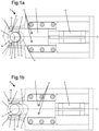
- FIG 1a a view along an axial direction of a clamping nest 1 according to the invention is shown.
- the clamping nest 1 comprises a bearing surface 2 and an opposite bearing surface which is formed by the slide 3 .
- the slider 3 has a recess 11 and the opposite support surface 2 has a recess 9 so that overall a fork-shaped area 10 for receiving the component 7 results.
- the fork axis is denoted by A.
- the component 7 is represented by a cam. However, other components, such as sensor wheels, are also possible.
- the component 7 has a circular-cylindrical recess 12 and an extension 19 extending radially away from the shaft.
- the bearing surface 2 and the opposite bearing surface formed by the slide 3 determine the axial positions of the component 7 in both axial directions in a form-fitting manner.
- the slide 3 can be moved in the direction of the fork axis A, ie in the radial direction, between a bracing position and a receiving position.
- two first clamping elements 5 are connected, which are spaced as far from the fork end of the slide 3 that they are in the Figure 1a engage the bracing position shown on the extension 19 of the component 7.
- the clamping elements are 5 in Figure 1a covered by the slider 3. In the perspective view of figure 2 however, these can be seen.
- Two second tensioning elements 4 are connected to the bearing surface 2 and are arranged at the fork-side end of the bearing surface 2 .
- the first clamping elements 5 and the second clamping elements 4 are designed and positioned in such a way that they fix the angular position of the component 7 within the fork-shaped area 10 in the clamping position.
- Both second clamping elements 4 act on the respective contact areas 21 on the central part 20 of the component 7 .
- the two contact areas 21 have an angular distance a relative to the axis of rotation B of the shaft, which in the present case is approximately 100°, for example.
- the first clamping elements 5 and the second clamping elements 4 are arranged in such a way that the component 7 can be accommodated in an orientation in which the extension 19 essentially points along the fork axis A towards the clamping nest 1 .
- the two first clamping elements 5 are at such a distance from one another that the extension 19 of the component 7 comes to lie between the two first clamping elements 5 in the clamping position.
- Figure 1b shows the clamping nest 1 according to the invention in the receiving position.
- the slide 3 is pulled back from the fork-side end of the bracing nest 1 compared to the bracing position.
- the clamping nest 1 has an adjustment unit 8 for this purpose.
- the second clamping elements 4 are formed in one piece with the bearing surface 2 in the illustrated embodiment, the first clamping elements 5 are connected to the slide 3 via fastening elements 15 .
- the second clamping elements 4 can also be designed separately and connected to the bearing surface 2 via fastening elements 13 . This is e.g. in figure 4 shown. at figure 4 it is a view of the clamping nest 1 according to the invention along a radial direction.
- the second clamping elements 4 are formed here by ball bearings, which are connected to the bearing surface 2 by means of fastening elements 13 .
- a shaft 16 with an axis of rotation B is also shown, which is inserted along the axial direction R into the circular-cylindrical recess 12 of the component 7 .
- the fixing element 6 Due to the viewing direction in the fork-shaped area 10 along the fork axis A (shown in figure 3 ) is in figure 4 now also the fixing element 6 can be seen, which is a leaf spring here.
- the fixing element 6 belongs to the bearing surface formed by the slide 3 and serves to fix the axial position of the component between the bearing surface 2 and the slide 3 by means of a press fit.
- the leaf spring 6 is arranged on the side of the slide 3 that faces the bearing surface 2 .
- the slide 3 is closed, ie when the slide 3 is moved from the receiving position into the bracing position, the component 7 is supported on the second clamping elements 4 . Therefore, the leaf spring 6 is compressed and exerts a force on the component 7 in the axial direction R from.
- the first clamping elements 5 act on both sides of the extension 19, so that the component 7 is clamped (see Fig figure 2 ).
- the extension 19 of the component 7 is also centered between the two first clamping elements 5 . Even if the component 7 was not inserted in the correct angular position, it is rotated into the predetermined angular position by closing the slide 3 .
- the slide 3 is moved away from the shaft 16 in the radial direction, so that the clamping nest 1 is brought back into the receiving position.
- the clamping nest 1 can now not be easily removed in the radial direction, since due to the expansion D of the second clamping elements 4 there is a form fit between the clamping nest 1 and the component 7 . Therefore, the clamping nest 1 is first moved in the axial direction until there is no longer a form fit in the radial direction, since the second clamping elements 4 have an extension D in the axial direction that is smaller than the distance between the opposite bearing surfaces 2, 3 1 can also be used with small working distances. The clamping nest 1 is then removed in the radial direction.
- figure 5 shows a longitudinal section through a clamping nest 1 not according to the invention without a slide.
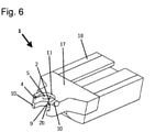
- FIG 6 shows a corresponding three-dimensional representation of the same clamping nest 1 without slider.
- the clamping nest 1 comprises a head part 17 and a carrier element 18.
- the head part 17 has a fork-shaped area 10 for receiving a component.
- the fork-shaped portion 10 has two opposing bearing surfaces 2 and 2b, the Determine the axial position of the component in both axial directions with a positive fit.
- the angular position of the component within the forked area 10 is fixed by the plurality of clamping elements 4 and 5 .
- the plurality of clamping elements 4.5 comprises two first clamping elements 5, which are spaced far enough from the fork-side end of the clamping nest 1 that they act on the extension of the component, and two second clamping elements 4, which are arranged so close to the fork-side end that they attack the central part of the component.
- the bearing surface 2b shown above comprises a fixing element on the side facing the other bearing surface 2 in order to fix the axial position of the component between the two bearing surfaces 2, 2b by means of a press fit.
- the fixing element which in the present case is formed by a leaf spring 6, is pressed together and the leaf spring 6 is fixed, then the component between the two bearing surfaces, in which it presses the component onto the bearing surface 2 .
- the Figures 7a - 7c schematically show different variants of fastening a component 7 on the shaft 16 .
- the shaft 16 has a widening 22 in each case, the diameter of which is larger than the inner diameter of the circular-cylindrical recess 12 of the component.
- the widening 22 is designed as a rolling.
Claims (17)
- Cage de serrage (1) pour le positionnement et l'assemblage d'un composant (7) sur un arbre (16), le composant (7) présentant une partie centrale (20) avec un évidement cylindrique circulaire (12) pour recevoir l'arbre (16),
la cage de serrage (1) présentant une région en forme de fourche (10) pour recevoir le composant (7) et la région en forme de fourche (10) comprenant une pluralité d'éléments de serrage (4, 5) qui fixent la position angulaire du composant (7) à l'intérieur de la région en forme de fourche (10),
la région en forme de fourche (10) comprenant deux surfaces d'appui opposées (2, 2b) qui fixent la position axiale du composant (7) par engagement par correspondance de formes dans les deux directions axiales,
caractérisée en ce que l'une des deux surfaces d'appui (2, 2b) est formée par un coulisseau déplaçable (3) qui peut être déplacé dans la direction radiale entre une position de serrage et une position de réception. - Cage de serrage selon la revendication 1,
caractérisée en ce que
les surfaces d'appui (2, 2b) sont réalisées de telle sorte que le composant (7) puisse être déplacé au moyen de la cage de serrage (1) dans les deux directions axiales le long de l'arbre (16) . - Cage de serrage selon l'une quelconque des revendications 1 à 2,
caractérisée en ce que
le composant (7) présente au moins une saillie (19) s'étendant radialement à l'écart de l'arbre (16) et la pluralité d'éléments de serrage (4, 5) est disposée de telle sorte que le composant (7) puisse être reçu dans une orientation dans laquelle la saillie (19) est tournée essentiellement vers la cage de serrage (1) le long de l'axe (A) de la fourche. - Cage de serrage selon l'une quelconque des revendications 1 à 3,
caractérisée en ce que
les surfaces d'appui (2, 2b) sont réalisées de telle sorte massife que le composant (7) puisse être pressé au moyen de la cage de serrage (1) sur un élargissement (22) de l'arbre (16). - Cage de serrage selon l'une quelconque des revendications 1 à 4,
caractérisée en ce que
au moins l'une des deux surfaces d'appui (2b) comprend un élément de fixation (6) sur le côté tourné vers l'autre surface d'appui (2), afin de fixer par ajustement serré la position axiale du composant (7) entre les surfaces d'appui (2, 2b). - Cage de serrage selon la revendication 5,
caractérisée en ce que
l'élément de fixation (6) est un ressort à lame ou un plastique flexible. - Cage de serrage selon l'une quelconque des revendications 1 à 6,
caractérisée en ce que
au moins l'un des éléments de serrage (4, 5) est réalisé sous forme de roulement à billes. - Cage de serrage selon l'une quelconque des revendications 1 à 7,
caractérisée en ce que
dans la position de serrage, le coulisseau (3) et l'autre surface d'appui (2) délimitent par engagement par correspondance de formes la position axiale du composant (7) dans les deux directions axiales et, dans la position de réception, le coulisseau (3) est en retrait par rapport à l'extrémité côté fourche de la cage de serrage (1) par comparaison avec la position de serrage. - Cage de serrage selon l'une quelconque des revendications 1 à 8,
caractérisée en ce
qu'au moins un premier élément de serrage (5) parmi la pluralité des éléments de serrage est relié au coulisseau (3) et un deuxième élément de serrage (4) parmi la pluralité des éléments de serrage (4, 5) est relié à la surface d'appui opposée (2) des deux surfaces d'appui. - Cage de serrage selon la revendication 9,
caractérisée en ce que
le premier élément de serrage (5) et le deuxième élément de serrage (4) sont réalisés et positionnés de telle sorte que dans la position de serrage, la position angulaire du composant (7) à l'intérieur de la région en forme de fourche (10) soit fixée. - Cage de serrage selon la revendication 10,
caractérisée en ce que
le composant (7) présente au moins une saillie (19) s'étendant radialement à l'écart de l'arbre (16) et le premier élément de serrage (5) est espacé de l'extrémité côté fourche du coulisseau (3) de telle sorte que dans la position de serrage, il vienne en prise contre la saillie (19) du composant (7), et le deuxième élément de serrage (4) est disposé tellement près de l'extrémité côté fourche de l'autre surface d'appui (2) qu'il vienne en prise dans la position de serrage sur la partie centrale (20). - Cage de serrage selon l'une quelconque des revendications 1 à 11,
caractérisée en ce que
le composant (7) présente au moins une saillie (19) s'étendant radialement à l'écart de l'arbre (16) et la cage de serrage (1) comprend deux premiers éléments de serrage (5) parmi la pluralité d'éléments de serrage, les deux premiers éléments de serrage (5) étant reliés au coulisseau (3) et étant espacés de l'extrémité côté fourche du coulisseau (3) de telle sorte qu'ils viennent en prise dans la position de serrage avec la saillie (19) du composant (7), ceux-ci étant espacés l'un de l'autre d'une distance telle que la saillie (19) du composant (7) vienne se placer, dans la position de serrage, entre les deux premiers éléments de serrage (5). - Cage de serrage selon l'une quelconque des revendications 1 à 12,
caractérisée en ce que
la cage de serrage comprend deux deuxièmes éléments de serrage (4) parmi la pluralité des éléments de serrage (4, 5), les deux deuxièmes éléments de serrage (4) étant reliés à la surface d'appui (2) opposée au coulisseau (3) et étant disposés tellement près de l'extrémité côté fourche qu'ils viennent en prise avec la partie centrale (20) du composant dans la position de serrage dans des régions de contact respectives (21), et la distance des deux régions de contact (21) étant comprise entre 50° et 130° par rapport à l'axe de rotation de l'arbre (16). - Cage de serrage selon les revendications 9 à 13,
caractérisée en ce que
le premier élément de serrage (5) et le deuxième élément de serrage (4) sont réalisés et positionnés de telle sorte qu'un composant reçu (7) soit tourné dans une position angulaire prédéterminée par déplacement du coulisseau (3) de la position de réception dans la position de serrage. - Cage de serrage selon l'une quelconque des revendications 11 à 14,
caractérisée en ce que
le deuxième élément de serrage (4) présente, dans la direction axiale, une étendue qui est inférieure à la distance entre les surfaces d'appui opposées (2, 2b). - Procédé pour le positionnement et l'assemblage d'un composant (7) sur un arbre (16) au moyen d'une cage de serrage (1) selon l'une quelconque des revendications 1 à 15, comprenant les étapes suivantes :a. fourniture d'un composant (7) avec un évidement cylindrique circulaire (12),b. réception du composant (7) dans la région en forme de fourche (10) de la cage de serrage,c. insertion d'un arbre (16) avec au moins un élargissement (22) dans l'évidement (12),d. pressage du composant (7) sur l'élargissement (22) au moyen de la cage de serrage (1),e. enlèvement de la cage de serrage (1) dans la direction radiale.
- Procédé pour le positionnement et l'assemblage d'un composant (7) sur un arbre au moyen d'une cage de serrage selon l'une quelconque des revendications 1 à 15, comprenant les étapes suivantes :a. fourniture d'un composant (7) avec un évidement cylindrique circulaire (12),b. fourniture de la cage de serrage (1) dans la position de réception,c. réception du composant (7) dans la région en forme de fourche (10) de la cage de serrage (1),d. déplacement du coulisseau (3) dans la direction radiale vers à l'arbre (16) de telle sorte que la cage de serrage (1) soit amenée dans la position de serrage,e. insertion d'un arbre avec au moins un élargissement (22) dans l'évidement (12),f. pressage du composant (7) sur l'élargissement (22) au moyen de la cage de serrage (1),g. déplacement du coulisseau (3) dans la direction radiale à l'écart de l'arbre (16) de telle sorte que la cage de serrage (1) soit amenée dans la position de réception,h. déplacement de la cage de serrage dans la direction axiale jusqu'à ce qu'il n'existe plus aucun engagement par correspondance de formes dans la direction radiale entre le composant (7) et tous les éléments de serrage (4, 5) de la cage de serrage (1),i. enlèvement de la cage de serrage (1) dans la direction radiale.
Applications Claiming Priority (2)
| Application Number | Priority Date | Filing Date | Title |
|---|---|---|---|
| DE102013005713.2A DE102013005713A1 (de) | 2013-03-30 | 2013-03-30 | Spannnest mit Fixierelementen |
| PCT/EP2014/000839 WO2014161649A1 (fr) | 2013-03-30 | 2014-03-28 | Cage de serrage pourvue d'éléments de fixation |
Publications (3)
| Publication Number | Publication Date |
|---|---|
| EP2978564A1 EP2978564A1 (fr) | 2016-02-03 |
| EP2978564B1 EP2978564B1 (fr) | 2018-03-07 |
| EP2978564B2 true EP2978564B2 (fr) | 2022-03-02 |
Family
ID=50513201
Family Applications (1)
| Application Number | Title | Priority Date | Filing Date |
|---|---|---|---|
| EP14717997.2A Active EP2978564B2 (fr) | 2013-03-30 | 2014-03-28 | Cage de serrage pourvue d'éléments de fixation |
Country Status (10)
| Country | Link |
|---|---|
| US (1) | US10557381B2 (fr) |
| EP (1) | EP2978564B2 (fr) |
| JP (1) | JP6302043B2 (fr) |
| KR (1) | KR102098984B1 (fr) |
| CN (1) | CN105102184B (fr) |
| BR (1) | BR112015024889A2 (fr) |
| DE (1) | DE102013005713A1 (fr) |
| HU (1) | HUE037385T2 (fr) |
| MX (1) | MX2015013717A (fr) |
| WO (1) | WO2014161649A1 (fr) |
Families Citing this family (2)
| Publication number | Priority date | Publication date | Assignee | Title |
|---|---|---|---|---|
| DE102013005713A1 (de) | 2013-03-30 | 2014-10-02 | Thyssenkrupp Presta Teccenter Ag | Spannnest mit Fixierelementen |
| DE102021213755A1 (de) | 2021-12-03 | 2023-06-07 | Mahle International Gmbh | Spannvorrichtung |
Family Cites Families (20)
| Publication number | Priority date | Publication date | Assignee | Title |
|---|---|---|---|---|
| DE3227693C2 (de) | 1982-07-24 | 1985-06-13 | Mahle Gmbh, 7000 Stuttgart | Verfahren zur Herstellung einer Nockenwelle für Verbrennungsmotoren |
| JPS6297722A (ja) | 1985-10-22 | 1987-05-07 | Nissan Motor Co Ltd | カムシヤフトの製造方法 |
| JPH07102409B2 (ja) | 1987-02-10 | 1995-11-08 | 正信 中村 | カムシヤフトの製造方法およびその装置 |
| FR2672834B1 (fr) * | 1991-02-18 | 1993-05-21 | Essilor Int | Organe de serrage et de prehension. |
| JP3040206B2 (ja) | 1991-08-14 | 2000-05-15 | クルップ・プレスタ・アーゲー | カムシャフトの製造装置 |
| JP3408644B2 (ja) * | 1994-10-07 | 2003-05-19 | 三菱重工業株式会社 | 部品圧入カムシャフト |
| FR2797793B1 (fr) * | 1999-08-24 | 2001-11-09 | Renault | Outillage pour la fabrication d'arbres a cames par dudgeonnage |
| JP2003106325A (ja) | 2001-09-28 | 2003-04-09 | Toyota Motor Corp | カムピース、カムピースの製造方法、及びカムシャフトの製造方法 |
| EP1611316B1 (fr) | 2003-03-08 | 2017-07-19 | ThyssenKrupp Presta TecCenter AG | Arbre a cames dont les cames sont engagees par pression |
| DE102004060807B3 (de) | 2004-12-17 | 2006-06-01 | Daimlerchrysler Ag | Vorrichtung zur Herstellung von gebauten Nockenwellen |
| DE102007056638B4 (de) * | 2007-11-24 | 2018-02-22 | Usk Karl Utz Sondermaschinen Gmbh | Verfahren und Vorrichtung zur Montage von einem Verbund, insbesondere aus einer Nockenwelle und einem Gehäuse |
| DE102008064194A1 (de) * | 2008-12-22 | 2010-07-01 | Usk Karl Utz Sondermaschinen Gmbh | Verfahren und Vorrichtung zur Positionierung mehrerer Funktionselemente in einer vorbestimmten Winkelposition auf einer Welle |
| DE102009060350B4 (de) * | 2009-12-24 | 2017-05-18 | Volkswagen Ag | Montagevorrichtung und Haltemodul |
| DE102009060349B4 (de) | 2009-12-24 | 2016-12-01 | Volkswagen Ag | Ausrichteeinheit und Montagevorrichtung |
| US8137379B2 (en) * | 2010-05-03 | 2012-03-20 | Josiah Labash | Pressure-applying device |
| DE102010045047A1 (de) | 2010-09-10 | 2012-03-15 | Thyssenkrupp Presta Teccenter Ag | Verfahren zum Zusammenbau eines Motormoduls |
| DE102010055123B4 (de) | 2010-12-18 | 2017-06-29 | Usk Karl Utz Sondermaschinen Gmbh | Verfahren und Vorrichtung zur Herstellung einer Nockenwelle |
| DE102011106981B4 (de) * | 2011-07-05 | 2017-01-12 | Emag Holding Gmbh | Verfahren und Vorrichtung zum Herstellen von Fügeverbindungen |
| KR101101862B1 (ko) | 2011-09-28 | 2012-01-05 | 주식회사 미보 | 캠 샤프트의 조립 장치 |
| DE102013005713A1 (de) | 2013-03-30 | 2014-10-02 | Thyssenkrupp Presta Teccenter Ag | Spannnest mit Fixierelementen |
-
2013
- 2013-03-30 DE DE102013005713.2A patent/DE102013005713A1/de not_active Ceased
-
2014
- 2014-03-28 BR BR112015024889A patent/BR112015024889A2/pt not_active Application Discontinuation
- 2014-03-28 MX MX2015013717A patent/MX2015013717A/es unknown
- 2014-03-28 CN CN201480019418.5A patent/CN105102184B/zh active Active
- 2014-03-28 WO PCT/EP2014/000839 patent/WO2014161649A1/fr active Application Filing
- 2014-03-28 US US14/781,445 patent/US10557381B2/en active Active
- 2014-03-28 EP EP14717997.2A patent/EP2978564B2/fr active Active
- 2014-03-28 HU HUE14717997A patent/HUE037385T2/hu unknown
- 2014-03-28 JP JP2016504515A patent/JP6302043B2/ja active Active
- 2014-03-28 KR KR1020157031118A patent/KR102098984B1/ko active IP Right Grant
Also Published As
| Publication number | Publication date |
|---|---|
| WO2014161649A1 (fr) | 2014-10-09 |
| EP2978564B1 (fr) | 2018-03-07 |
| KR20150135526A (ko) | 2015-12-02 |
| JP2016516596A (ja) | 2016-06-09 |
| HUE037385T2 (hu) | 2018-08-28 |
| BR112015024889A2 (pt) | 2017-07-18 |
| US20160053639A1 (en) | 2016-02-25 |
| MX2015013717A (es) | 2016-02-26 |
| CN105102184B (zh) | 2017-03-15 |
| DE102013005713A1 (de) | 2014-10-02 |
| US10557381B2 (en) | 2020-02-11 |
| CN105102184A (zh) | 2015-11-25 |
| EP2978564A1 (fr) | 2016-02-03 |
| KR102098984B1 (ko) | 2020-04-09 |
| JP6302043B2 (ja) | 2018-03-28 |
Similar Documents
| Publication | Publication Date | Title |
|---|---|---|
| EP1600679A1 (fr) | Dispositif de raccordement en plastique pour fixer un tuyau souple | |
| EP3423744B1 (fr) | Dispositif de pré-positionnement pour une bride profilée et ensemble de liaison doté d'un dispositif de pré-positionnement de ce type | |
| DE102017113379A1 (de) | Passives Auslassventil mit äußerer Torsionsfeder | |
| WO2012104242A1 (fr) | Dispositif destiné à modifier la position angulaire relative d' un arbre à cames par rapport au vilebrequin d'un moteur à combustion interne | |
| EP3129668B1 (fr) | Ensemble palier segmenté avec cage en matière plastique fixée par complémentarité de formes | |
| EP2574743B1 (fr) | Module de moteur comprenant un support de palier ainsi que son procédé de montage | |
| EP3110587B1 (fr) | Système de fixation destiné à une panne | |
| DE102016218410A1 (de) | Schwenkhebelanordnung für eine Scheibenbremse mit Führungsorgan sowie Bausatz zur Montage der Schwenkhebelanordnung | |
| EP2978564B2 (fr) | Cage de serrage pourvue d'éléments de fixation | |
| DE102014115008A1 (de) | Vorrichtung zum positionsgerechten Befestigen einer Antennenanordnung an einer Fläche | |
| EP0275441A1 (fr) | Dispositif de serrage | |
| DE102007036554B4 (de) | Deckel-Lager-Anordnung und Verfahren zum Montieren einer Aktuatorwelle | |
| DE102012004810A1 (de) | Scharnier, Scharnierteil und Verfahren zur Herstellung eines Scharnierteils | |
| EP3119641B1 (fr) | Agencement de liaison pour liaison pivotante d'un siège de véhicule et siège de véhicule | |
| EP3807012A1 (fr) | Centrifugeuse | |
| DE102009051470B4 (de) | Gleitlager sowie Brennkraftmaschine | |
| EP1762768B1 (fr) | Dispositif écarteur ajustable | |
| EP3374646B1 (fr) | Système permettant de fixer un élément plan à un élément structural et attache de fixation devant être utilisée dans un système de ce type | |
| DE102007013782B3 (de) | Verfahren zur Herstellung einer Klappenvorrichtung für Verbrennungskraftmaschinen sowie derartige Klappenvorrichtung | |
| WO2003011503A1 (fr) | Element d'ecartement pour une pince de serrage et pince de serrage | |
| EP3614030B1 (fr) | Élément de conduite pourvu de support intégré pour un moyen de fixation | |
| DE10126438A1 (de) | Schaltschiene mit einer Schaltgabel | |
| DE102017110640A1 (de) | Anordnung einer Scheibenbremse für ein Nutzfahrzeug | |
| DE102019108553B4 (de) | Verfahren zur Montage eines Druckfederelements | |
| DE102015108710B4 (de) | Spannelement für eine Spannvorrichtung, sowie Spannvorrichtung |
Legal Events
| Date | Code | Title | Description |
|---|---|---|---|
| PUAI | Public reference made under article 153(3) epc to a published international application that has entered the european phase |
Free format text: ORIGINAL CODE: 0009012 |
|
| 17P | Request for examination filed |
Effective date: 20150924 |
|
| AK | Designated contracting states |
Kind code of ref document: A1 Designated state(s): AL AT BE BG CH CY CZ DE DK EE ES FI FR GB GR HR HU IE IS IT LI LT LU LV MC MK MT NL NO PL PT RO RS SE SI SK SM TR |
|
| AX | Request for extension of the european patent |
Extension state: BA ME |
|
| DAX | Request for extension of the european patent (deleted) | ||
| GRAP | Despatch of communication of intention to grant a patent |
Free format text: ORIGINAL CODE: EPIDOSNIGR1 |
|
| STAA | Information on the status of an ep patent application or granted ep patent |
Free format text: STATUS: GRANT OF PATENT IS INTENDED |
|
| INTG | Intention to grant announced |
Effective date: 20171004 |
|
| GRAS | Grant fee paid |
Free format text: ORIGINAL CODE: EPIDOSNIGR3 |
|
| GRAA | (expected) grant |
Free format text: ORIGINAL CODE: 0009210 |
|
| STAA | Information on the status of an ep patent application or granted ep patent |
Free format text: STATUS: THE PATENT HAS BEEN GRANTED |
|
| RAP1 | Party data changed (applicant data changed or rights of an application transferred) |
Owner name: THYSSENKRUPP PRESTA TECCENTER AG |
|
| AK | Designated contracting states |
Kind code of ref document: B1 Designated state(s): AL AT BE BG CH CY CZ DE DK EE ES FI FR GB GR HR HU IE IS IT LI LT LU LV MC MK MT NL NO PL PT RO RS SE SI SK SM TR |
|
| REG | Reference to a national code |
Ref country code: GB Ref legal event code: FG4D Free format text: NOT ENGLISH |
|
| REG | Reference to a national code |
Ref country code: CH Ref legal event code: EP Ref country code: AT Ref legal event code: REF Ref document number: 976024 Country of ref document: AT Kind code of ref document: T Effective date: 20180315 |
|
| REG | Reference to a national code |
Ref country code: DE Ref legal event code: R096 Ref document number: 502014007533 Country of ref document: DE |
|
| REG | Reference to a national code |
Ref country code: IE Ref legal event code: FG4D Free format text: LANGUAGE OF EP DOCUMENT: GERMAN |
|
| REG | Reference to a national code |
Ref country code: FR Ref legal event code: PLFP Year of fee payment: 5 |
|
| REG | Reference to a national code |
Ref country code: SE Ref legal event code: TRGR |
|
| REG | Reference to a national code |
Ref country code: NL Ref legal event code: MP Effective date: 20180307 |
|
| REG | Reference to a national code |
Ref country code: LT Ref legal event code: MG4D |
|
| PG25 | Lapsed in a contracting state [announced via postgrant information from national office to epo] |
Ref country code: HR Free format text: LAPSE BECAUSE OF FAILURE TO SUBMIT A TRANSLATION OF THE DESCRIPTION OR TO PAY THE FEE WITHIN THE PRESCRIBED TIME-LIMIT Effective date: 20180307 Ref country code: LT Free format text: LAPSE BECAUSE OF FAILURE TO SUBMIT A TRANSLATION OF THE DESCRIPTION OR TO PAY THE FEE WITHIN THE PRESCRIBED TIME-LIMIT Effective date: 20180307 Ref country code: CY Free format text: LAPSE BECAUSE OF FAILURE TO SUBMIT A TRANSLATION OF THE DESCRIPTION OR TO PAY THE FEE WITHIN THE PRESCRIBED TIME-LIMIT Effective date: 20180307 Ref country code: ES Free format text: LAPSE BECAUSE OF FAILURE TO SUBMIT A TRANSLATION OF THE DESCRIPTION OR TO PAY THE FEE WITHIN THE PRESCRIBED TIME-LIMIT Effective date: 20180307 Ref country code: FI Free format text: LAPSE BECAUSE OF FAILURE TO SUBMIT A TRANSLATION OF THE DESCRIPTION OR TO PAY THE FEE WITHIN THE PRESCRIBED TIME-LIMIT Effective date: 20180307 Ref country code: NO Free format text: LAPSE BECAUSE OF FAILURE TO SUBMIT A TRANSLATION OF THE DESCRIPTION OR TO PAY THE FEE WITHIN THE PRESCRIBED TIME-LIMIT Effective date: 20180607 |
|
| REG | Reference to a national code |
Ref country code: HU Ref legal event code: AG4A Ref document number: E037385 Country of ref document: HU |
|
| PG25 | Lapsed in a contracting state [announced via postgrant information from national office to epo] |
Ref country code: LV Free format text: LAPSE BECAUSE OF FAILURE TO SUBMIT A TRANSLATION OF THE DESCRIPTION OR TO PAY THE FEE WITHIN THE PRESCRIBED TIME-LIMIT Effective date: 20180307 Ref country code: BG Free format text: LAPSE BECAUSE OF FAILURE TO SUBMIT A TRANSLATION OF THE DESCRIPTION OR TO PAY THE FEE WITHIN THE PRESCRIBED TIME-LIMIT Effective date: 20180607 Ref country code: GR Free format text: LAPSE BECAUSE OF FAILURE TO SUBMIT A TRANSLATION OF THE DESCRIPTION OR TO PAY THE FEE WITHIN THE PRESCRIBED TIME-LIMIT Effective date: 20180608 Ref country code: RS Free format text: LAPSE BECAUSE OF FAILURE TO SUBMIT A TRANSLATION OF THE DESCRIPTION OR TO PAY THE FEE WITHIN THE PRESCRIBED TIME-LIMIT Effective date: 20180307 |
|
| PG25 | Lapsed in a contracting state [announced via postgrant information from national office to epo] |
Ref country code: MT Free format text: LAPSE BECAUSE OF FAILURE TO SUBMIT A TRANSLATION OF THE DESCRIPTION OR TO PAY THE FEE WITHIN THE PRESCRIBED TIME-LIMIT Effective date: 20180307 |
|
| PG25 | Lapsed in a contracting state [announced via postgrant information from national office to epo] |
Ref country code: AL Free format text: LAPSE BECAUSE OF FAILURE TO SUBMIT A TRANSLATION OF THE DESCRIPTION OR TO PAY THE FEE WITHIN THE PRESCRIBED TIME-LIMIT Effective date: 20180307 Ref country code: RO Free format text: LAPSE BECAUSE OF FAILURE TO SUBMIT A TRANSLATION OF THE DESCRIPTION OR TO PAY THE FEE WITHIN THE PRESCRIBED TIME-LIMIT Effective date: 20180307 Ref country code: PL Free format text: LAPSE BECAUSE OF FAILURE TO SUBMIT A TRANSLATION OF THE DESCRIPTION OR TO PAY THE FEE WITHIN THE PRESCRIBED TIME-LIMIT Effective date: 20180307 Ref country code: EE Free format text: LAPSE BECAUSE OF FAILURE TO SUBMIT A TRANSLATION OF THE DESCRIPTION OR TO PAY THE FEE WITHIN THE PRESCRIBED TIME-LIMIT Effective date: 20180307 Ref country code: NL Free format text: LAPSE BECAUSE OF FAILURE TO SUBMIT A TRANSLATION OF THE DESCRIPTION OR TO PAY THE FEE WITHIN THE PRESCRIBED TIME-LIMIT Effective date: 20180307 |
|
| REG | Reference to a national code |
Ref country code: CH Ref legal event code: PL |
|
| PG25 | Lapsed in a contracting state [announced via postgrant information from national office to epo] |
Ref country code: SM Free format text: LAPSE BECAUSE OF FAILURE TO SUBMIT A TRANSLATION OF THE DESCRIPTION OR TO PAY THE FEE WITHIN THE PRESCRIBED TIME-LIMIT Effective date: 20180307 Ref country code: SK Free format text: LAPSE BECAUSE OF FAILURE TO SUBMIT A TRANSLATION OF THE DESCRIPTION OR TO PAY THE FEE WITHIN THE PRESCRIBED TIME-LIMIT Effective date: 20180307 |
|
| REG | Reference to a national code |
Ref country code: DE Ref legal event code: R026 Ref document number: 502014007533 Country of ref document: DE |
|
| PLBI | Opposition filed |
Free format text: ORIGINAL CODE: 0009260 |
|
| REG | Reference to a national code |
Ref country code: BE Ref legal event code: MM Effective date: 20180331 |
|
| REG | Reference to a national code |
Ref country code: IE Ref legal event code: MM4A |
|
| PG25 | Lapsed in a contracting state [announced via postgrant information from national office to epo] |
Ref country code: PT Free format text: LAPSE BECAUSE OF FAILURE TO SUBMIT A TRANSLATION OF THE DESCRIPTION OR TO PAY THE FEE WITHIN THE PRESCRIBED TIME-LIMIT Effective date: 20180709 Ref country code: LU Free format text: LAPSE BECAUSE OF NON-PAYMENT OF DUE FEES Effective date: 20180328 |
|
| 26 | Opposition filed |
Opponent name: MAHLE INTERNATIONAL GMBH Effective date: 20181205 |
|
| PLAX | Notice of opposition and request to file observation + time limit sent |
Free format text: ORIGINAL CODE: EPIDOSNOBS2 |
|
| PG25 | Lapsed in a contracting state [announced via postgrant information from national office to epo] |
Ref country code: IE Free format text: LAPSE BECAUSE OF NON-PAYMENT OF DUE FEES Effective date: 20180328 Ref country code: DK Free format text: LAPSE BECAUSE OF FAILURE TO SUBMIT A TRANSLATION OF THE DESCRIPTION OR TO PAY THE FEE WITHIN THE PRESCRIBED TIME-LIMIT Effective date: 20180307 Ref country code: MC Free format text: LAPSE BECAUSE OF FAILURE TO SUBMIT A TRANSLATION OF THE DESCRIPTION OR TO PAY THE FEE WITHIN THE PRESCRIBED TIME-LIMIT Effective date: 20180307 |
|
| PG25 | Lapsed in a contracting state [announced via postgrant information from national office to epo] |
Ref country code: LI Free format text: LAPSE BECAUSE OF NON-PAYMENT OF DUE FEES Effective date: 20180331 Ref country code: SI Free format text: LAPSE BECAUSE OF FAILURE TO SUBMIT A TRANSLATION OF THE DESCRIPTION OR TO PAY THE FEE WITHIN THE PRESCRIBED TIME-LIMIT Effective date: 20180307 Ref country code: BE Free format text: LAPSE BECAUSE OF NON-PAYMENT OF DUE FEES Effective date: 20180331 Ref country code: CH Free format text: LAPSE BECAUSE OF NON-PAYMENT OF DUE FEES Effective date: 20180331 |
|
| PLBB | Reply of patent proprietor to notice(s) of opposition received |
Free format text: ORIGINAL CODE: EPIDOSNOBS3 |
|
| PG25 | Lapsed in a contracting state [announced via postgrant information from national office to epo] |
Ref country code: TR Free format text: LAPSE BECAUSE OF FAILURE TO SUBMIT A TRANSLATION OF THE DESCRIPTION OR TO PAY THE FEE WITHIN THE PRESCRIBED TIME-LIMIT Effective date: 20180307 |
|
| PG25 | Lapsed in a contracting state [announced via postgrant information from national office to epo] |
Ref country code: MK Free format text: LAPSE BECAUSE OF NON-PAYMENT OF DUE FEES Effective date: 20180307 |
|
| PG25 | Lapsed in a contracting state [announced via postgrant information from national office to epo] |
Ref country code: IS Free format text: LAPSE BECAUSE OF FAILURE TO SUBMIT A TRANSLATION OF THE DESCRIPTION OR TO PAY THE FEE WITHIN THE PRESCRIBED TIME-LIMIT Effective date: 20180707 |
|
| REG | Reference to a national code |
Ref country code: AT Ref legal event code: MM01 Ref document number: 976024 Country of ref document: AT Kind code of ref document: T Effective date: 20190328 |
|
| PG25 | Lapsed in a contracting state [announced via postgrant information from national office to epo] |
Ref country code: AT Free format text: LAPSE BECAUSE OF NON-PAYMENT OF DUE FEES Effective date: 20190328 |
|
| PGFP | Annual fee paid to national office [announced via postgrant information from national office to epo] |
Ref country code: IT Payment date: 20210329 Year of fee payment: 8 Ref country code: CZ Payment date: 20210329 Year of fee payment: 8 |
|
| PGFP | Annual fee paid to national office [announced via postgrant information from national office to epo] |
Ref country code: SE Payment date: 20210319 Year of fee payment: 8 |
|
| PGFP | Annual fee paid to national office [announced via postgrant information from national office to epo] |
Ref country code: HU Payment date: 20210425 Year of fee payment: 8 |
|
| PUAH | Patent maintained in amended form |
Free format text: ORIGINAL CODE: 0009272 |
|
| STAA | Information on the status of an ep patent application or granted ep patent |
Free format text: STATUS: PATENT MAINTAINED AS AMENDED |
|
| 27A | Patent maintained in amended form |
Effective date: 20220302 |
|
| AK | Designated contracting states |
Kind code of ref document: B2 Designated state(s): AL AT BE BG CH CY CZ DE DK EE ES FI FR GB GR HR HU IE IS IT LI LT LU LV MC MK MT NL NO PL PT RO RS SE SI SK SM TR |
|
| REG | Reference to a national code |
Ref country code: DE Ref legal event code: R102 Ref document number: 502014007533 Country of ref document: DE |
|
| REG | Reference to a national code |
Ref country code: SE Ref legal event code: NAV |
|
| PG25 | Lapsed in a contracting state [announced via postgrant information from national office to epo] |
Ref country code: CZ Free format text: LAPSE BECAUSE OF FAILURE TO SUBMIT A TRANSLATION OF THE DESCRIPTION OR TO PAY THE FEE WITHIN THE PRESCRIBED TIME-LIMIT Effective date: 20180307 |
|
| PG25 | Lapsed in a contracting state [announced via postgrant information from national office to epo] |
Ref country code: HU Free format text: LAPSE BECAUSE OF NON-PAYMENT OF DUE FEES Effective date: 20220329 |
|
| PGFP | Annual fee paid to national office [announced via postgrant information from national office to epo] |
Ref country code: FR Payment date: 20230324 Year of fee payment: 10 |
|
| PG25 | Lapsed in a contracting state [announced via postgrant information from national office to epo] |
Ref country code: IT Free format text: LAPSE BECAUSE OF NON-PAYMENT OF DUE FEES Effective date: 20220328 |
|
| PGFP | Annual fee paid to national office [announced via postgrant information from national office to epo] |
Ref country code: GB Payment date: 20230322 Year of fee payment: 10 Ref country code: DE Payment date: 20220727 Year of fee payment: 10 |
|
| P01 | Opt-out of the competence of the unified patent court (upc) registered |
Effective date: 20230530 |
|
| PGFP | Annual fee paid to national office [announced via postgrant information from national office to epo] |
Ref country code: DE Payment date: 20240320 Year of fee payment: 11 Ref country code: GB Payment date: 20240320 Year of fee payment: 11 |