EP0275441A1 - Dispositif de serrage - Google Patents
Dispositif de serrage Download PDFInfo
- Publication number
- EP0275441A1 EP0275441A1 EP87118003A EP87118003A EP0275441A1 EP 0275441 A1 EP0275441 A1 EP 0275441A1 EP 87118003 A EP87118003 A EP 87118003A EP 87118003 A EP87118003 A EP 87118003A EP 0275441 A1 EP0275441 A1 EP 0275441A1
- Authority
- EP
- European Patent Office
- Prior art keywords
- clamping device
- locking body
- ball
- tool
- bore
- Prior art date
- Legal status (The legal status is an assumption and is not a legal conclusion. Google has not performed a legal analysis and makes no representation as to the accuracy of the status listed.)
- Granted
Links
Images


Classifications
-
- B—PERFORMING OPERATIONS; TRANSPORTING
- B23—MACHINE TOOLS; METAL-WORKING NOT OTHERWISE PROVIDED FOR
- B23B—TURNING; BORING
- B23B31/00—Chucks; Expansion mandrels; Adaptations thereof for remote control
- B23B31/02—Chucks
- B23B31/10—Chucks characterised by the retaining or gripping devices or their immediate operating means
- B23B31/107—Retention by laterally-acting detents, e.g. pins, screws, wedges; Retention by loose elements, e.g. balls
- B23B31/1075—Retention by screws
- B23B31/1077—Retention by screws acting on a floating pin
-
- B—PERFORMING OPERATIONS; TRANSPORTING
- B23—MACHINE TOOLS; METAL-WORKING NOT OTHERWISE PROVIDED FOR
- B23B—TURNING; BORING
- B23B2260/00—Details of constructional elements
- B23B2260/022—Balls
-
- Y—GENERAL TAGGING OF NEW TECHNOLOGICAL DEVELOPMENTS; GENERAL TAGGING OF CROSS-SECTIONAL TECHNOLOGIES SPANNING OVER SEVERAL SECTIONS OF THE IPC; TECHNICAL SUBJECTS COVERED BY FORMER USPC CROSS-REFERENCE ART COLLECTIONS [XRACs] AND DIGESTS
- Y10—TECHNICAL SUBJECTS COVERED BY FORMER USPC
- Y10T—TECHNICAL SUBJECTS COVERED BY FORMER US CLASSIFICATION
- Y10T408/00—Cutting by use of rotating axially moving tool
- Y10T408/94—Tool-support
- Y10T408/95—Tool-support with tool-retaining means
-
- Y—GENERAL TAGGING OF NEW TECHNOLOGICAL DEVELOPMENTS; GENERAL TAGGING OF CROSS-SECTIONAL TECHNOLOGIES SPANNING OVER SEVERAL SECTIONS OF THE IPC; TECHNICAL SUBJECTS COVERED BY FORMER USPC CROSS-REFERENCE ART COLLECTIONS [XRACs] AND DIGESTS
- Y10—TECHNICAL SUBJECTS COVERED BY FORMER USPC
- Y10T—TECHNICAL SUBJECTS COVERED BY FORMER US CLASSIFICATION
- Y10T409/00—Gear cutting, milling, or planing
- Y10T409/30—Milling
- Y10T409/309352—Cutter spindle or spindle support
- Y10T409/309408—Cutter spindle or spindle support with cutter holder
Definitions
- the invention relates to a clamping device with the features listed in the preamble of claim 1.
- the balls can be acted upon by eccentric inner surfaces of a clamping ring rotatably mounted on the ring flange about the system axis, by means of which the balls are clamped radially inwards against the locking body.
- This radially inwardly directed clamping pressure exerted by the balls is deflected in an axial clamping direction by the inclined surfaces at the front ends of the locking body.
- This clamping device has the disadvantage that both the clamping ring and the inclined surfaces of the locking body are only in point contact with the balls. As a result, this clamping device is at risk of wear and only safe to a limited extent against the inevitable effects of vibration during operation.
- the invention has for its object to design a tensioning device of the type mentioned so that it is wear-resistant and vibration-proof without sacrificing repeatability and easy manipulation.
- Such clamping devices are used in automated tool changing systems, in which the carrier must be able to hold different tools with a long service life and repeatability at short intervals.
- the solution according to the invention ensures surface contact in the area of the individual members of the tensioning device, which ensures high-level vibration damping and, at the same time, low specific surface pressures.
- the characterizing feature of claim 5 ensures uniformity of the clamping pressures acting on both sides of the locking body.
- the characterizing feature of claim 6 ensures that the locking body is automatically pushed back into the central position in the pulling out of the pin from the fitting bore of the carrier, in which the pulling out process is not impaired.
- the characteristic feature of claim 7 ensures that the locking body is always functional with respect to the rotational position of its longitudinal axis. An inexpensive manufacture of the locking body and the transverse recess is ensured by claim 8.
- the characteristic feature of claim 10 enables the clamping movement to wedge both partial bodies of the locking body within the transverse bore, which is particularly useful for vibration security. Due to the characterizing feature of claim 11, the clamping device can also be closed and released in the axial direction, for example from the front of the tool. By the characteristic of the Claim 14 is in turn favored the vibration resistance.
- the feature of claim 16 enables an unimpeded insertion of the fitting pin into the fitting bore without an end of the locking body protruding approximately from the transverse recess hindering the insertion movement.
- the further features of the invention solve problems based on the fact that the balls lie freely rotatably in their bearing pan. This could have the consequence that, when the tool is removed, a ball rotates, for example under external mechanical influences (vibrations, shocks, etc.), into a position in which its capping surface lies, for example, inside the bearing socket.
- the clamping device When the clamping device is closed, the inclined surface of the locking body would then no longer be punctually impacted by the capping surface, but by a spherical peripheral region of the spherical surface.
- a perfect clamping of the tool in the holder would no longer be guaranteed; on the other hand, there would be the danger that the local pressure would cause such high local pressures on the ball surface that the ball would be destroyed.
- the features of claim 17 are provided. Since the ball in the released state of the clamping device with the level of its capping surface is automatically brought into a parallel position to the system axis, the capping surface is always frontal to the locking body, regardless of the rotational position of the pressure screw, thereby ensuring unimpeded insertion of the fitting pin and error-free tensioning of the capping surface the inclined surface of the locking body are guaranteed.
- the specified rest position of the ball capping surface means that the clamping device can be released and closed with only a minimal displacement of the balls relative to the locking mechanism body possible. When tensioning itself, the ball is deflected from the rest position by the action of its capping surface from the inclined surface of the locking body against the moment of the restoring element.
- a structurally advantageous embodiment of the restoring element and its attachment to the ball or pressure screw is specified.
- an elongated, resilient plastic rod or the like can also be used. Find use.
- the ball can be deflected in all lateral spatial directions with respect to the bearing socket, a restoring moment always being exerted on the ball regardless of the deflection direction. Due to the funnel-like or conical widening of the two blind holes, there are no sharp corners and edges in the contact area of the spring part. In addition, the assembly, in particular the insertion of the spring part into the blind holes, is greatly facilitated by the widening.
- the tensioning device By designing the tensioning device according to claim 24, the restoring moment caused by the spring part is transmitted to the ball without delay. Due to the mutual contact of the spring part over its entire length in the area of the two blind bores in the bearing socket and the ball, the restoring force generated by the spring part is transmitted directly to the ball over its entire length.
- the two blind holes are concentric to the axis of rotation of the pressure screw or the ball.
- the axis of rotation of the ball is to be understood as the axis which runs through the center of the capping surface and is perpendicular to the latter.
- the specified construction makes assembly easier.
- the elongated spring part only needs to be inserted into the blind hole of the ball and both components then pressed together into the bearing socket.
- the end of the spring part protruding from the blind bore of the ball is inserted straight into the blind bore of the bearing socket.
- the funnel-like or conical widening of the blind bores has the advantage that the introduction is particularly easy.
- the length of the spring part specified in claim 26 in turn has a positive effect on the restoring torque that can be generated, since this increases with the length of the spring part.
- the features specified in claim 27 serve to improve the storage properties of the ball in the bearing pan. Because of the openings of the two blind holes, the bearing of the ball itself is deteriorated, especially since the opening of the ball blind hole on the surface section diametrically opposite the ball capping surface. The effective storage area is therefore reduced especially in the areas of storage where the greatest bearing pressures normally occur. Accordingly, it is advantageous if the overlap area of the openings of the two blind bores has a minimal surface area and consequently a shape which essentially corresponds to the cross section of the spring part.
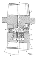
- the 1-3 essentially consists of the cutter holder, hereinafter referred to as tool 1, and the holder 2, e.g. the drive spindle of a machine tool.
- the tool 1 can be inserted with a rear fitting pin 3 into an axially identical fitting bore 4 of the carrier 2 and can be fixed there by locking elements both against an axial movement in the direction of the system axis 5 and against a rotational movement about the system axis 5.
- the locking member is at least one locking body 7 which is displaceable in the radial direction in a continuous radial transverse recess 6 of the fitting pin 3
- System axis 5 form an acute angle 11 which closes in the direction of tool 1.
- Each inclined surface 9, 10 is acted upon by the pressure surface of a pressure body which can be screwed radially into the ring flange 12 surrounding the fitting bore 4.
- This pressure surface is the capping surface 13 of a ball 14.
- Each ball 14 is supported in a bearing pan 16 at the end face of a pressure screw 15 which can be radially screwed from the outside through the ring flange and is held captively in this.
- angles 11 formed by the two inclined surfaces 9, 10 with the axis of the fitting bore 4 or the system axis 5 are of the same size.
- the locking body 7 can only be displaced to a limited extent in the longitudinal direction of the transverse recess 6 such that it can only project radially beyond the fitting pin 3 with an inclined surface 9 or 10.
- a longitudinal groove 17 of limited length is arranged on the outer circumference of the locking body 7, into which a groove permanently connected to the fitting pin 3 in the direction of the system axis 5 pointing pin 18 protrudes.
- the locking body 7 is still non-rotatably guided in the transverse recess 6.
- the transverse recess 6 can be a bore and the locking body 7 can be a cylindrical bolt.
- the locking body 7 is provided in the center with an annular groove 19 or in the longitudinal direction of the system axis 5 is penetrated by a through hole 20 which overlaps an axial coolant hole 21 in the fitting pin 3.
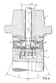
- the locking body is divided into two, with each part body 22, 23 being assigned an inclined surface 9, 10 and the parting planes 24 of both part bodies 22, 23 forming an acute angle 25 with the system axis 5 or the longitudinal axis of the fitting bore 4 and lie together.
- the locking body is also divided into two. It consists of the partial bodies 27, 28, the mutually facing dividing surfaces 29, 30 of which form an acute angle 31 which opens in the direction of the tool 1.
- the dividing surfaces 29, 30 of the partial bodies 27, 28 can be spread apart by a wedge-like tensioning member 32 that can be driven longitudinally displaceably in the direction of the system axis 5.
- the wedge surfaces 34, 35 of the tensioning member 32 lie equally on the mutually facing dividing surfaces 29, 30 of the locking bodies 27, 28.
- the wedge intermediate position of the tendon 32 between the locking bodies 28, 29 can be self-locking; then there must be sufficient pressure to retract the tendon 32 from its clamping position.
- a Hirth toothing 36 which is arranged in the region of the axial contact surface between the ring flange 12 of the carrier 2 and the counter surface of the tool 1.
- the ends of the locking body 7 or the partial body 22, 23 or 27, 28 are provided on their side facing away from the tool 1 with counter-bevels 37, 38 which form a preferably acute angle 39 which opens in the direction of the tool.
- the counter-bevels 37, 38 push the locking body 7 into its central position when the fitting pin 3 is inserted.
- the tensioning device is tensioned by screwing in at least one of the two pressure screws 15 from the outside of the carrier 2.
- the balls 14 with their capping surfaces 13 bear against the inclined surfaces 9, 10 of the locking body 7 or the partial bodies 22, 23 (FIG. 4) or 27, 28 (FIG. 6) and thereby generate an axial pressure on the fitting pin 3 towards the inside of the fitting bore 4.
- the anti-rotation device between the carrier 2 and the tool 1 can be improved by means of a fitting pin 40 (FIGS. 1, 3 and 4) or by means of a Hirth toothing (plank serration) 36 (FIG. 6-9) become effective in the area of the axial contact surface between the ring flange 12 of the carrier 2 and the counter surface of the tool 1.
- a loosening of the clamping connection is possible by loosening the same pressure screw 15 that was previously tensioned.
- the locking body 7 or its sub-bodies 22, 23 automatically slide back into a central position in the transverse recess 6, due to the inclined surfaces 9, 10, in which removal is possible without hindrance.
- the tensioning and loosening can take place not only by tightening both pressure screws 15 but also by advancing and retracting the tensioning member 32.
- fitting pin 3 is connected to the tool 1 and the fitting hole 4 is part of the carrier 2, then a kinematically reversed assignment of the fitting pin 3 or fitting hole 4 is possible without changing the inventive concept.
- the invention favors a short construction of the tensioning device in any case in the direction of the system axis 5.
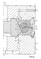
- This reset device shown in particular in FIGS. 8 and 9, consists of an elongated coil spring 50, the length of which rests in two blind bores 51, 52 in the bearing socket 16 of the pressure screw 15 and the ball 14, respectively.
- the two blind bores 51, 52 are each concentric to the axes of rotation 53, 54 of pressure screw 15 or ball 14.
- the axis of rotation 54 of the ball 14 is the axis which runs through the center of the capping surface 13 and is arranged at right angles to it.
- the two blind bores 51, 52 are formed in the direction of their openings 55 in a funnel-like manner.
- the diameter of the blind bores 51, 52 corresponds to that of the coil spring 50.
- the coil spring 50 is fixed in the blind bore 52 at its pressure screw-side end 56, for example by gluing.
- the ball-side end 57 lies freely in the blind bore 51.
- the length of the coil spring 50 essentially corresponds to the total depth of the two blind bores 51, 52.
- the capping surface 13 of the ball 14 faces the inclined surface 9, the capping surface 13 being oriented at right angles to the relative displacement direction 58 and parallel to the system axis 5.
- the two blind bores 51, 52 are congruent with their openings 55.
- the clamping device is closed by screwing in at least one of the two pressure screws 15 from the outside of the carrier 2.
- the balls 14 lay with their capping surfaces 13 on the inclined surfaces 9 of the locking body 7 and thereby generate an axial pressure on the fitting pin 3 in the direction of the inside of the fitting bore 4.
- the helical spring becomes 50 deformed in the two blind bores 51, 52 and in particular laterally deflected.
- the coil spring 50 generates a restoring moment because it shows a tendency to stretch. If the tensioning device is released again by moving the locking body 7 and ball 14 relative to one another, the ball 14 is returned to the rest position shown in FIG. 2 by contraction of the coil spring 50, in which the capping surface 13 is perpendicular to the relative displacement direction 58 or parallel to the system axis 5 is arranged. As shown in FIG. 9, the helical spring 50 lies in the tensioned position of ball 14 and locking body 7 over its entire length in the region of the two blind bores 51, 52 on mutually opposite side walls 59, 60 of the two blind bores 51, 52. The openings 55 of the two blind bores have an overlap area, the area and shape of which essentially correspond to the cross section of the coil spring 50.
Priority Applications (1)
| Application Number | Priority Date | Filing Date | Title |
|---|---|---|---|
| AT87118003T ATE60532T1 (de) | 1986-12-23 | 1987-12-05 | Spannvorrichtung. |
Applications Claiming Priority (6)
| Application Number | Priority Date | Filing Date | Title |
|---|---|---|---|
| DE3644091 | 1986-12-23 | ||
| DE3644091 | 1986-12-23 | ||
| DE3716932 | 1987-05-20 | ||
| DE19873716932 DE3716932A1 (de) | 1987-05-20 | 1987-05-20 | Spannvorrichtung |
| DE3734699 | 1987-10-14 | ||
| DE3734699 | 1987-10-14 |
Publications (2)
| Publication Number | Publication Date |
|---|---|
| EP0275441A1 true EP0275441A1 (fr) | 1988-07-27 |
| EP0275441B1 EP0275441B1 (fr) | 1991-01-30 |
Family
ID=27195289
Family Applications (1)
| Application Number | Title | Priority Date | Filing Date |
|---|---|---|---|
| EP87118003A Expired - Lifetime EP0275441B1 (fr) | 1986-12-23 | 1987-12-05 | Dispositif de serrage |
Country Status (6)
| Country | Link |
|---|---|
| US (1) | US4797041A (fr) |
| EP (1) | EP0275441B1 (fr) |
| AT (1) | ATE60532T1 (fr) |
| CA (1) | CA1298493C (fr) |
| DE (1) | DE3767867D1 (fr) |
| ES (1) | ES2021333B3 (fr) |
Cited By (7)
| Publication number | Priority date | Publication date | Assignee | Title |
|---|---|---|---|---|
| FR2623573A1 (fr) * | 1987-11-24 | 1989-05-26 | Komet Stahlhater Werkzeugfabri | Dispositif pour solidariser deux parties constitutives de machines, notamment deux parties d'outillage de machines-outils |
| EP0390342A2 (fr) * | 1989-03-31 | 1990-10-03 | Renishaw plc | Mécanisme de raccordement |
| DE4123966A1 (de) * | 1991-07-19 | 1993-01-21 | Heller Geb Gmbh Maschf | Spannvorrichtung fuer einzelwerkzeuge |
| US5212872A (en) * | 1989-03-31 | 1993-05-25 | Reinshaw Plc | Touch probe |
| US5957639A (en) * | 1996-10-04 | 1999-09-28 | E.P.B. Emile Pfalzgraf (Societe Anonyme) | Hollow cone device for gripping attachments |
| FR2941161A1 (fr) * | 2009-01-22 | 2010-07-23 | Univ Grenoble 1 | Ensemble d'usinage comprenant un outil et un porte-outil, machine tornante et outil tel qu'un foret. |
| WO2012013629A1 (fr) * | 2010-07-26 | 2012-02-02 | Rainer Pfister | Mandrin de serrage expansible hydrauliquement |
Families Citing this family (7)
| Publication number | Priority date | Publication date | Assignee | Title |
|---|---|---|---|---|
| EP0295315B1 (fr) * | 1987-06-16 | 1991-03-27 | Fried. Krupp Gesellschaft mit beschränkter Haftung | Assemblage d'outil |
| US4976574A (en) * | 1989-09-08 | 1990-12-11 | Komet Stahlhalter- Und Werkzeugfabrik Robert Breuning Gmbh | Device for connecting two tool parts |
| DE4024644A1 (de) * | 1989-09-09 | 1991-03-14 | Komet Stahlhalter Werkzeug | Vorrichtung zum loesbaren verbinden eines werkzeugs mit einer maschinenspindel |
| DE102004009217A1 (de) * | 2004-02-12 | 2005-09-01 | Gühring, Jörg, Dr. | Spannelement für Werkzeugspanner |
| US20060115337A1 (en) * | 2004-12-01 | 2006-06-01 | Fusao Higashi | Runout eliminating collet chuck |
| DE102010039793A1 (de) * | 2010-03-02 | 2011-09-08 | Komet Group Gmbh | Vorrichtung zur Verbindung zweier Bauteile |
| US10596642B2 (en) * | 2017-08-23 | 2020-03-24 | Gemini Precision Machining, Inc. | Tool and tool holder assembly |
Citations (8)
| Publication number | Priority date | Publication date | Assignee | Title |
|---|---|---|---|---|
| EP0013646A1 (fr) * | 1979-01-09 | 1980-07-23 | The Bendix Corporation | Assemblage d'un mandrin et d'une pince de serrage |
| GB2094191A (en) * | 1981-03-06 | 1982-09-15 | Komet Stahlhalter Werkzeug | Boring tool shank |
| GB2127333A (en) * | 1982-09-21 | 1984-04-11 | Illinois Tool Works | Tool and toolholder couplings in machine tools |
| EP0123220A2 (fr) * | 1983-04-20 | 1984-10-31 | Komet Stahlhalter- und Werkzeugfabrik Robert Breuning GmbH | Broche de machine-outil et porte-outil correspondant |
| GB2155823A (en) * | 1984-03-24 | 1985-10-02 | Valenite Modco | Improvements relating to tool holders |
| GB2164276A (en) * | 1984-09-14 | 1986-03-19 | Beck August Gmbh Co | Axial clamping connection |
| EP0185842A1 (fr) * | 1984-12-19 | 1986-07-02 | Gte Valenite Corporation | Dispositif pour accoupler un porte-outil échangeable à une broche |
| EP0204671A2 (fr) * | 1985-05-08 | 1986-12-10 | Santrade Ltd. | Dispositif d'accouplement d'un outil |
Family Cites Families (3)
| Publication number | Priority date | Publication date | Assignee | Title |
|---|---|---|---|---|
| DE1087875B (de) * | 1958-04-05 | 1960-08-25 | Schiess Ag | Einrichtung zum Befestigen oder Loesen der Verriegelung zwischen einer Arbeitsspindel und einem kegeligen Werkzeugschaft |
| GB1557345A (en) * | 1977-02-15 | 1979-12-05 | Leitner K | Chuck |
| JPS6116204U (ja) * | 1984-06-29 | 1986-01-30 | 大昭和精機株式会社 | コンビネ−シヨンロツクホルダ− |
-
1987
- 1987-12-05 ES ES87118003T patent/ES2021333B3/es not_active Expired - Lifetime
- 1987-12-05 EP EP87118003A patent/EP0275441B1/fr not_active Expired - Lifetime
- 1987-12-05 DE DE8787118003T patent/DE3767867D1/de not_active Expired - Lifetime
- 1987-12-05 AT AT87118003T patent/ATE60532T1/de not_active IP Right Cessation
- 1987-12-22 CA CA000555070A patent/CA1298493C/fr not_active Expired - Lifetime
- 1987-12-23 US US07/137,151 patent/US4797041A/en not_active Expired - Fee Related
Patent Citations (8)
| Publication number | Priority date | Publication date | Assignee | Title |
|---|---|---|---|---|
| EP0013646A1 (fr) * | 1979-01-09 | 1980-07-23 | The Bendix Corporation | Assemblage d'un mandrin et d'une pince de serrage |
| GB2094191A (en) * | 1981-03-06 | 1982-09-15 | Komet Stahlhalter Werkzeug | Boring tool shank |
| GB2127333A (en) * | 1982-09-21 | 1984-04-11 | Illinois Tool Works | Tool and toolholder couplings in machine tools |
| EP0123220A2 (fr) * | 1983-04-20 | 1984-10-31 | Komet Stahlhalter- und Werkzeugfabrik Robert Breuning GmbH | Broche de machine-outil et porte-outil correspondant |
| GB2155823A (en) * | 1984-03-24 | 1985-10-02 | Valenite Modco | Improvements relating to tool holders |
| GB2164276A (en) * | 1984-09-14 | 1986-03-19 | Beck August Gmbh Co | Axial clamping connection |
| EP0185842A1 (fr) * | 1984-12-19 | 1986-07-02 | Gte Valenite Corporation | Dispositif pour accoupler un porte-outil échangeable à une broche |
| EP0204671A2 (fr) * | 1985-05-08 | 1986-12-10 | Santrade Ltd. | Dispositif d'accouplement d'un outil |
Cited By (11)
| Publication number | Priority date | Publication date | Assignee | Title |
|---|---|---|---|---|
| FR2623573A1 (fr) * | 1987-11-24 | 1989-05-26 | Komet Stahlhater Werkzeugfabri | Dispositif pour solidariser deux parties constitutives de machines, notamment deux parties d'outillage de machines-outils |
| EP0390342A2 (fr) * | 1989-03-31 | 1990-10-03 | Renishaw plc | Mécanisme de raccordement |
| EP0390342A3 (fr) * | 1989-03-31 | 1991-01-09 | Renishaw plc | Mécanisme de raccordement |
| US5040931A (en) * | 1989-03-31 | 1991-08-20 | Renishaw Plc | Coupling mechanism |
| US5212872A (en) * | 1989-03-31 | 1993-05-25 | Reinshaw Plc | Touch probe |
| DE4123966A1 (de) * | 1991-07-19 | 1993-01-21 | Heller Geb Gmbh Maschf | Spannvorrichtung fuer einzelwerkzeuge |
| US5244322A (en) * | 1991-07-19 | 1993-09-14 | Gebr. Heller Maschinenfabrik Gesellschaft mit beschrankter Haftung | Clamping device for individual tools |
| US5957639A (en) * | 1996-10-04 | 1999-09-28 | E.P.B. Emile Pfalzgraf (Societe Anonyme) | Hollow cone device for gripping attachments |
| FR2941161A1 (fr) * | 2009-01-22 | 2010-07-23 | Univ Grenoble 1 | Ensemble d'usinage comprenant un outil et un porte-outil, machine tornante et outil tel qu'un foret. |
| WO2012013629A1 (fr) * | 2010-07-26 | 2012-02-02 | Rainer Pfister | Mandrin de serrage expansible hydrauliquement |
| US9440295B2 (en) | 2010-07-26 | 2016-09-13 | Rainer Pfister | Hydraulic expanding lock |
Also Published As
| Publication number | Publication date |
|---|---|
| DE3767867D1 (de) | 1991-03-07 |
| ES2021333B3 (es) | 1991-11-01 |
| ATE60532T1 (de) | 1991-02-15 |
| US4797041A (en) | 1989-01-10 |
| CA1298493C (fr) | 1992-04-07 |
| EP0275441B1 (fr) | 1991-01-30 |
Similar Documents
| Publication | Publication Date | Title |
|---|---|---|
| EP2325502B1 (fr) | Agencement et procédé pour relier un accessoire avec une table d'opération | |
| DE3605569A1 (de) | Schluesselloses bohrfutter sowie verfahren zur herstellung von schluessellosen bohrfuttern | |
| EP0507147A1 (fr) | Accouplement | |
| EP0275441B1 (fr) | Dispositif de serrage | |
| EP0623413A1 (fr) | Dispositif de serrage rapide pour lames de scie sauteuse | |
| DE3031216C2 (de) | Spannfutter für Gewindebohrer | |
| EP0622142B1 (fr) | Porte outil, en particulier mandrin à changement rapide | |
| DE3817893C2 (fr) | ||
| AT393302B (de) | Vorrichtung zur verbindung zweier werkzeugteile | |
| EP0193020B1 (fr) | Dispositif d'outillage avec tête interchangeable | |
| EP0410104B1 (fr) | Outil d'usinage par enlèvement de copeaux | |
| EP0962280B1 (fr) | Dispositif d'alignement | |
| EP1262266B1 (fr) | Dispositif de fixation | |
| DE2322027C3 (de) | In eine Arbeitsspindel einsetzbares Werkzeugfutter | |
| EP0087623B1 (fr) | Procédé d'assemblage d'une vis-mère double montée sur une broche filetée | |
| DE3439668A1 (de) | Schluesselloses schnellspannfutter | |
| DE2241608B2 (de) | In eine Arbeitsspindel einsetzbares Werkzeugfutter | |
| DE2615322C2 (de) | Befestigungsvorrichtung für Türschilder bzw. Türrosetten | |
| EP1905545A2 (fr) | Tendeur à ressort pour ressort cylindrique | |
| EP0417613A1 (fr) | Dispositif pour le couplage des deux pièces de machines-outils | |
| EP1896219B1 (fr) | Point de raccordement | |
| DE2557248C3 (de) | Vorrichtung zum Feststellen von Maschinenteilen zueinander | |
| DE4040774C1 (fr) | ||
| EP0598289B1 (fr) | Boulon de centrage pour la fixation, le centrage et/ou le positionnement des éléments avec des trous de centrage | |
| EP0582792B1 (fr) | Dispositif de réglage de la force de serrage dans un dispositif de serrage en particulier pour un étau de machine-outil |
Legal Events
| Date | Code | Title | Description |
|---|---|---|---|
| PUAI | Public reference made under article 153(3) epc to a published international application that has entered the european phase |
Free format text: ORIGINAL CODE: 0009012 |
|
| AK | Designated contracting states |
Kind code of ref document: A1 Designated state(s): AT BE CH DE ES FR GB IT LI LU NL SE |
|
| 17P | Request for examination filed |
Effective date: 19880812 |
|
| 17Q | First examination report despatched |
Effective date: 19891016 |
|
| GRAA | (expected) grant |
Free format text: ORIGINAL CODE: 0009210 |
|
| AK | Designated contracting states |
Kind code of ref document: B1 Designated state(s): AT BE CH DE ES FR GB IT LI LU NL SE |
|
| REF | Corresponds to: |
Ref document number: 60532 Country of ref document: AT Date of ref document: 19910215 Kind code of ref document: T |
|
| REF | Corresponds to: |
Ref document number: 3767867 Country of ref document: DE Date of ref document: 19910307 |
|
| GBT | Gb: translation of ep patent filed (gb section 77(6)(a)/1977) | ||
| ITF | It: translation for a ep patent filed |
Owner name: UFFICIO BREVETTI RICCARDI & C. |
|
| ET | Fr: translation filed | ||
| PGFP | Annual fee paid to national office [announced via postgrant information from national office to epo] |
Ref country code: DE Payment date: 19911031 Year of fee payment: 5 |
|
| PGFP | Annual fee paid to national office [announced via postgrant information from national office to epo] |
Ref country code: SE Payment date: 19911108 Year of fee payment: 5 |
|
| PGFP | Annual fee paid to national office [announced via postgrant information from national office to epo] |
Ref country code: GB Payment date: 19911125 Year of fee payment: 5 |
|
| PLBE | No opposition filed within time limit |
Free format text: ORIGINAL CODE: 0009261 |
|
| STAA | Information on the status of an ep patent application or granted ep patent |
Free format text: STATUS: NO OPPOSITION FILED WITHIN TIME LIMIT |
|
| PGFP | Annual fee paid to national office [announced via postgrant information from national office to epo] |
Ref country code: FR Payment date: 19911211 Year of fee payment: 5 |
|
| PGFP | Annual fee paid to national office [announced via postgrant information from national office to epo] |
Ref country code: ES Payment date: 19911220 Year of fee payment: 5 |
|
| PGFP | Annual fee paid to national office [announced via postgrant information from national office to epo] |
Ref country code: AT Payment date: 19911223 Year of fee payment: 5 |
|
| PGFP | Annual fee paid to national office [announced via postgrant information from national office to epo] |
Ref country code: LU Payment date: 19911227 Year of fee payment: 5 |
|
| PGFP | Annual fee paid to national office [announced via postgrant information from national office to epo] |
Ref country code: NL Payment date: 19911231 Year of fee payment: 5 |
|
| PGFP | Annual fee paid to national office [announced via postgrant information from national office to epo] |
Ref country code: BE Payment date: 19920107 Year of fee payment: 5 |
|
| PGFP | Annual fee paid to national office [announced via postgrant information from national office to epo] |
Ref country code: CH Payment date: 19920120 Year of fee payment: 5 |
|
| 26N | No opposition filed | ||
| EPTA | Lu: last paid annual fee | ||
| PG25 | Lapsed in a contracting state [announced via postgrant information from national office to epo] |
Ref country code: LU Free format text: LAPSE BECAUSE OF NON-PAYMENT OF DUE FEES Effective date: 19921205 Ref country code: GB Effective date: 19921205 Ref country code: AT Effective date: 19921205 |
|
| PG25 | Lapsed in a contracting state [announced via postgrant information from national office to epo] |
Ref country code: SE Effective date: 19921206 |
|
| PG25 | Lapsed in a contracting state [announced via postgrant information from national office to epo] |
Ref country code: LI Effective date: 19921231 Ref country code: CH Effective date: 19921231 Ref country code: BE Effective date: 19921231 |
|
| BERE | Be: lapsed |
Owner name: HERTEL A.G. WERKZEUGE + HARTSTOFFE Effective date: 19921231 |
|
| PG25 | Lapsed in a contracting state [announced via postgrant information from national office to epo] |
Ref country code: NL Effective date: 19930701 |
|
| GBPC | Gb: european patent ceased through non-payment of renewal fee |
Effective date: 19921205 |
|
| NLV4 | Nl: lapsed or anulled due to non-payment of the annual fee | ||
| PG25 | Lapsed in a contracting state [announced via postgrant information from national office to epo] |
Ref country code: FR Effective date: 19930831 |
|
| REG | Reference to a national code |
Ref country code: CH Ref legal event code: PL |
|
| PG25 | Lapsed in a contracting state [announced via postgrant information from national office to epo] |
Ref country code: DE Effective date: 19930901 |
|
| REG | Reference to a national code |
Ref country code: FR Ref legal event code: ST |
|
| PG25 | Lapsed in a contracting state [announced via postgrant information from national office to epo] |
Ref country code: ES Free format text: LAPSE BECAUSE OF NON-PAYMENT OF DUE FEES Effective date: 19931206 |
|
| EUG | Se: european patent has lapsed |
Ref document number: 87118003.0 Effective date: 19930709 |
|
| REG | Reference to a national code |
Ref country code: ES Ref legal event code: FD2A Effective date: 19940113 |
|
| PG25 | Lapsed in a contracting state [announced via postgrant information from national office to epo] |
Ref country code: IT Free format text: LAPSE BECAUSE OF NON-PAYMENT OF DUE FEES Effective date: 20051205 |