EP2978564B2 - Spannnest mit fixierelementen - Google Patents
Spannnest mit fixierelementen Download PDFInfo
- Publication number
- EP2978564B2 EP2978564B2 EP14717997.2A EP14717997A EP2978564B2 EP 2978564 B2 EP2978564 B2 EP 2978564B2 EP 14717997 A EP14717997 A EP 14717997A EP 2978564 B2 EP2978564 B2 EP 2978564B2
- Authority
- EP
- European Patent Office
- Prior art keywords
- clamping
- component
- nest
- shaft
- clamping nest
- Prior art date
- Legal status (The legal status is an assumption and is not a legal conclusion. Google has not performed a legal analysis and makes no representation as to the accuracy of the status listed.)
- Active
Links
Images


Classifications
-
- B—PERFORMING OPERATIONS; TRANSPORTING
- B23—MACHINE TOOLS; METAL-WORKING NOT OTHERWISE PROVIDED FOR
- B23P—METAL-WORKING NOT OTHERWISE PROVIDED FOR; COMBINED OPERATIONS; UNIVERSAL MACHINE TOOLS
- B23P11/00—Connecting or disconnecting metal parts or objects by metal-working techniques not otherwise provided for
-
- F—MECHANICAL ENGINEERING; LIGHTING; HEATING; WEAPONS; BLASTING
- F01—MACHINES OR ENGINES IN GENERAL; ENGINE PLANTS IN GENERAL; STEAM ENGINES
- F01L—CYCLICALLY OPERATING VALVES FOR MACHINES OR ENGINES
- F01L1/00—Valve-gear or valve arrangements, e.g. lift-valve gear
- F01L1/02—Valve drive
- F01L1/04—Valve drive by means of cams, camshafts, cam discs, eccentrics or the like
- F01L1/047—Camshafts
-
- B—PERFORMING OPERATIONS; TRANSPORTING
- B23—MACHINE TOOLS; METAL-WORKING NOT OTHERWISE PROVIDED FOR
- B23P—METAL-WORKING NOT OTHERWISE PROVIDED FOR; COMBINED OPERATIONS; UNIVERSAL MACHINE TOOLS
- B23P2700/00—Indexing scheme relating to the articles being treated, e.g. manufactured, repaired, assembled, connected or other operations covered in the subgroups
- B23P2700/02—Camshafts
-
- F—MECHANICAL ENGINEERING; LIGHTING; HEATING; WEAPONS; BLASTING
- F01—MACHINES OR ENGINES IN GENERAL; ENGINE PLANTS IN GENERAL; STEAM ENGINES
- F01L—CYCLICALLY OPERATING VALVES FOR MACHINES OR ENGINES
- F01L1/00—Valve-gear or valve arrangements, e.g. lift-valve gear
- F01L1/02—Valve drive
- F01L1/04—Valve drive by means of cams, camshafts, cam discs, eccentrics or the like
- F01L1/047—Camshafts
- F01L2001/0471—Assembled camshafts
-
- F—MECHANICAL ENGINEERING; LIGHTING; HEATING; WEAPONS; BLASTING
- F01—MACHINES OR ENGINES IN GENERAL; ENGINE PLANTS IN GENERAL; STEAM ENGINES
- F01L—CYCLICALLY OPERATING VALVES FOR MACHINES OR ENGINES
- F01L1/00—Valve-gear or valve arrangements, e.g. lift-valve gear
- F01L1/02—Valve drive
- F01L1/04—Valve drive by means of cams, camshafts, cam discs, eccentrics or the like
- F01L1/047—Camshafts
- F01L2001/0475—Hollow camshafts
-
- F—MECHANICAL ENGINEERING; LIGHTING; HEATING; WEAPONS; BLASTING
- F01—MACHINES OR ENGINES IN GENERAL; ENGINE PLANTS IN GENERAL; STEAM ENGINES
- F01L—CYCLICALLY OPERATING VALVES FOR MACHINES OR ENGINES
- F01L2303/00—Manufacturing of components used in valve arrangements
- F01L2303/01—Tools for producing, mounting or adjusting, e.g. some part of the distribution
Definitions
- the alignment unit After the component is attached, the alignment unit is moved in the opposite axial direction until it is separated from the component and can then be removed.
- the installation space on and around the camshaft is very limited. A movement in the axial direction to remove the tool is therefore not always possible.
- the UK 102009060350 discloses the features of the preamble of claim 1.
- the object of the present invention to provide a clamping nest which can be removed in the radial direction after the component has been installed.
- This object is achieved with a clamping nest having the features of claim 1.
- the two opposing bearing surfaces ensure that the component is held securely in the fork-shaped area and the clamping nest can be removed in the radial direction after assembly.
- this design has the advantage that the component can be moved in both axial directions during assembly with the help of the clamping bracket.
- the axial direction is understood to mean the direction in which the shaft extends. It is therefore the direction of the axis of rotation of the shaft. In relation to a component, this is the direction of the axis of symmetry of the circular-cylindrical recess for receiving the shaft.
- the radial direction means any direction that is perpendicular to the axial direction.
- the component is often a cam.
- the component then has at least one extension extending radially away from the shaft.
- Other components such as sensor wheels are also possible.
- the majority of the clamping elements are arranged in such a way that the component can be accommodated in an orientation in which the extension essentially points along the fork axis towards the clamping nest. This enables a particularly slim configuration of the clamping nest in a direction that runs perpendicularly to the fork axis and perpendicularly to the axial direction.
- the component is first positioned in the vicinity of a widening of the shaft and then pressed onto this widening by means of the clamping nest, so that the component is fixed there.
- the widening can in particular involve rolling.
- a greater effort is required. It is therefore advantageous if the contact surfaces are designed to be so solid that the component can be pressed onto a widening of the shaft by means of the clamping nest.
- the two bearing surfaces includes a fixing element on the side facing the other bearing surface, in order to fix the axial position of the component between the bearing surfaces by means of a press fit.
- the fixing element can be formed, for example, by a leaf spring, which is compressed when the component is pushed into the clamping nest and thus presses the component onto the opposite support surface.
- the fixing element can also be formed by a flexible plastic, which is also pressed together when the component is pushed into the clamping nest and thus presses the component in the direction of the opposite support surface.
- the leaf spring which is typically made of metal, has the additional advantage that it is less sensitive to the high temperatures that can occur during the joining process.
- At least one of the clamping elements is designed as a ball bearing.
- This has the advantage that the friction of the clamping nest is reduced compared to a one-piece clamping element. Friction occurs, for example, when the component is rotated to a predetermined angular position by means of the clamping elements by a kind of funnel effect, as described below. The surface of the component slides along the clamping elements. Wear of the clamping nest can therefore occur due to friction. This is reduced by the ball bearings according to the invention.
- one of the two bearing surfaces of the clamping nest is formed by an adjustable slide which can be moved in the radial direction between a clamping position and a receiving position.
- the slide and the other bearing surface limit the axial position of the component in both axial directions.
- the slide is pulled back from the fork-side end of the clamping nest compared to the bracing position.
- the axial position of the component is thus fixed in a form-fitting manner only in one axial direction.
- the design of one contact surface as a slide makes it possible to insert the component into the clamping nest in the axial direction while the slide is in the receiving position.
- the axial position of the component is in both axial directions fixed positively, so that the component can be moved in both axial directions on the shaft.
- the attachment and movement is done in one step by pressing the component onto an expansion of the shaft.
- the slide can be moved to the receiving position so that the clamping nest can be removed either in the axial direction or in the radial direction or by a combined axial/radial movement, as explained further below. This thus enables a particularly flexible use of the clamping nest according to the invention.
- At least one first clamping element from the plurality of clamping elements is advantageously connected to the slide and a second clamping element from the plurality of clamping elements is connected to the opposite bearing surface of the two bearing surfaces.
- first clamping element and the second clamping element are designed and positioned in such a way that in the clamping position the angular position of the component is fixed within the fork-shaped area.
- the first clamping element and the second clamping element also prevent the component from rotating about the axial direction . Since the angular position of components, especially cams, on a shaft is important for subsequent engine control, it is necessary that the components do not twist unintentionally during the assembly process. In addition, there are special assembly processes that include axial twisting of the components around the axial direction. So it can be advantageous, if necessary following a temporary pre-positioning, to join the components to a widening of the shaft and then to twist them axially at this position.
- a particularly good fixation in the radial direction can be achieved if the first clamping element is spaced far enough from the fork-side end of the slide that it acts on the extension of the component in the clamping position and the second clamping element is arranged so close to the fork-side end of the other bearing surface, that it acts on the central part in the braced position.
- the clamping nest advantageously has two first clamping elements from the plurality of clamping elements, both of which are connected to the slide and are spaced far enough from the fork-side end of the slide that they Attack bracing position on the extension of the component, and each other have such a distance that the extension of the component comes to rest in the bracing position between the first two clamping elements.
- the tensioning element advantageously has two second tensioning elements from the plurality of tensioning elements, both of which are connected to the bearing surface opposite the slide.
- the two second clamping elements are arranged so close to the fork-side end that in the clamping position they act in the respective contact areas on the central part of the component, the distance between the two contact areas being between 50° and 130°, in particular between 70° and 110°, based on is the axis of rotation of the shaft.
- the first clamping element and the second clamping element are designed and positioned in such a way that a received component is rotated into a predetermined angular position by moving the slide from the receiving position into the clamping position.
- the first clamping element connected to the slide causes a kind of funnel effect when the slide is moved from the receiving position into the clamping position.
- the component is supported on the second clamping element.
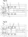
- FIG 1a a view along an axial direction of a clamping nest 1 according to the invention is shown.
- the clamping nest 1 comprises a bearing surface 2 and an opposite bearing surface which is formed by the slide 3 .
- the slider 3 has a recess 11 and the opposite support surface 2 has a recess 9 so that overall a fork-shaped area 10 for receiving the component 7 results.
- the fork axis is denoted by A.
- the component 7 is represented by a cam. However, other components, such as sensor wheels, are also possible.
- the component 7 has a circular-cylindrical recess 12 and an extension 19 extending radially away from the shaft.
- the bearing surface 2 and the opposite bearing surface formed by the slide 3 determine the axial positions of the component 7 in both axial directions in a form-fitting manner.
- the slide 3 can be moved in the direction of the fork axis A, ie in the radial direction, between a bracing position and a receiving position.
- two first clamping elements 5 are connected, which are spaced as far from the fork end of the slide 3 that they are in the Figure 1a engage the bracing position shown on the extension 19 of the component 7.
- the clamping elements are 5 in Figure 1a covered by the slider 3. In the perspective view of figure 2 however, these can be seen.
- Two second tensioning elements 4 are connected to the bearing surface 2 and are arranged at the fork-side end of the bearing surface 2 .
- the first clamping elements 5 and the second clamping elements 4 are designed and positioned in such a way that they fix the angular position of the component 7 within the fork-shaped area 10 in the clamping position.
- Both second clamping elements 4 act on the respective contact areas 21 on the central part 20 of the component 7 .
- the two contact areas 21 have an angular distance a relative to the axis of rotation B of the shaft, which in the present case is approximately 100°, for example.
- the first clamping elements 5 and the second clamping elements 4 are arranged in such a way that the component 7 can be accommodated in an orientation in which the extension 19 essentially points along the fork axis A towards the clamping nest 1 .
- the two first clamping elements 5 are at such a distance from one another that the extension 19 of the component 7 comes to lie between the two first clamping elements 5 in the clamping position.
- Figure 1b shows the clamping nest 1 according to the invention in the receiving position.
- the slide 3 is pulled back from the fork-side end of the bracing nest 1 compared to the bracing position.
- the clamping nest 1 has an adjustment unit 8 for this purpose.
- the second clamping elements 4 are formed in one piece with the bearing surface 2 in the illustrated embodiment, the first clamping elements 5 are connected to the slide 3 via fastening elements 15 .
- the second clamping elements 4 can also be designed separately and connected to the bearing surface 2 via fastening elements 13 . This is e.g. in figure 4 shown. at figure 4 it is a view of the clamping nest 1 according to the invention along a radial direction.
- the second clamping elements 4 are formed here by ball bearings, which are connected to the bearing surface 2 by means of fastening elements 13 .
- a shaft 16 with an axis of rotation B is also shown, which is inserted along the axial direction R into the circular-cylindrical recess 12 of the component 7 .
- the fixing element 6 Due to the viewing direction in the fork-shaped area 10 along the fork axis A (shown in figure 3 ) is in figure 4 now also the fixing element 6 can be seen, which is a leaf spring here.
- the fixing element 6 belongs to the bearing surface formed by the slide 3 and serves to fix the axial position of the component between the bearing surface 2 and the slide 3 by means of a press fit.
- the leaf spring 6 is arranged on the side of the slide 3 that faces the bearing surface 2 .
- the slide 3 is closed, ie when the slide 3 is moved from the receiving position into the bracing position, the component 7 is supported on the second clamping elements 4 . Therefore, the leaf spring 6 is compressed and exerts a force on the component 7 in the axial direction R from.
- the first clamping elements 5 act on both sides of the extension 19, so that the component 7 is clamped (see Fig figure 2 ).
- the extension 19 of the component 7 is also centered between the two first clamping elements 5 . Even if the component 7 was not inserted in the correct angular position, it is rotated into the predetermined angular position by closing the slide 3 .
- the slide 3 is moved away from the shaft 16 in the radial direction, so that the clamping nest 1 is brought back into the receiving position.
- the clamping nest 1 can now not be easily removed in the radial direction, since due to the expansion D of the second clamping elements 4 there is a form fit between the clamping nest 1 and the component 7 . Therefore, the clamping nest 1 is first moved in the axial direction until there is no longer a form fit in the radial direction, since the second clamping elements 4 have an extension D in the axial direction that is smaller than the distance between the opposite bearing surfaces 2, 3 1 can also be used with small working distances. The clamping nest 1 is then removed in the radial direction.
- figure 5 shows a longitudinal section through a clamping nest 1 not according to the invention without a slide.
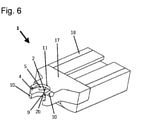
- FIG 6 shows a corresponding three-dimensional representation of the same clamping nest 1 without slider.
- the clamping nest 1 comprises a head part 17 and a carrier element 18.
- the head part 17 has a fork-shaped area 10 for receiving a component.
- the fork-shaped portion 10 has two opposing bearing surfaces 2 and 2b, the Determine the axial position of the component in both axial directions with a positive fit.
- the angular position of the component within the forked area 10 is fixed by the plurality of clamping elements 4 and 5 .
- the plurality of clamping elements 4.5 comprises two first clamping elements 5, which are spaced far enough from the fork-side end of the clamping nest 1 that they act on the extension of the component, and two second clamping elements 4, which are arranged so close to the fork-side end that they attack the central part of the component.
- the bearing surface 2b shown above comprises a fixing element on the side facing the other bearing surface 2 in order to fix the axial position of the component between the two bearing surfaces 2, 2b by means of a press fit.
- the fixing element which in the present case is formed by a leaf spring 6, is pressed together and the leaf spring 6 is fixed, then the component between the two bearing surfaces, in which it presses the component onto the bearing surface 2 .
- the Figures 7a - 7c schematically show different variants of fastening a component 7 on the shaft 16 .
- the shaft 16 has a widening 22 in each case, the diameter of which is larger than the inner diameter of the circular-cylindrical recess 12 of the component.
- the widening 22 is designed as a rolling.
Landscapes
- Engineering & Computer Science (AREA)
- Mechanical Engineering (AREA)
- General Engineering & Computer Science (AREA)
- Clamps And Clips (AREA)
- Automatic Assembly (AREA)
Description
- Bei der Herstellung von Nockenwellen werden unterschiedliche Bauteile separat hergestellt und auf eine vorgefertigte Welle gefügt. Zum Fügen werden die Bauteile auf der Welle axial auf eine Aufweitung der Welle bewegt. Dies wird typischerweise mit einem als Spannnest bezeichneten Werkzeug durchgeführt. Ein derartiges Werkzeug ist aus der
DE 102009060349 A1 bekannt. Mit dem dort als Ausrichteinheit bezeichneten Werkzeug wird das Bauteil gegriffen und entlang der Welle, d.h. in axialer Richtung, bewegt. Zusätzlich weist die Ausrichteinheit verschiedene Elemente auf, mit denen die Winkelposition des Bauteils eingestellt wird. In axialer Richtung weist die dort gezeigte Ausrichteinheit nur einen Anschlag auf mit dem das Bauteil formschlüssig in axialer Richtung fixiert ist. Das Bauteil kann also mit der Ausrichteinheit nur in einer axialen Richtung bewegt werden. Nach Befestigung des Bauteils wird die Ausrichteinheit in die entgegengesetzte axiale Richtung bewegt, bis sie vom Bauteil getrennt ist und dann entfernt werden kann. Bei heutigen Motoren ist der Bauraum auf und um die Nockenwelle herum jedoch stark begrenzt. Eine Bewegung in axialer Richtung zum Entfernen des Werkzeuges ist daher nicht immer möglich. DieDE 102009060350 offenbart die Merkmale des Oberbegriffes des Anspruchs 1. - Aufgabe der vorliegenden Erfindung ist es daher, ein Spannnest zur Verfügung zu stellen, das nach Montage des Bauteils in radialer Richtung entfernt werden kann. Diese Aufgabe wird gelöst mit einem Spannnest mit den Merkmalen des Anspruchs 1. Durch die beiden gegenüber liegenden Auflageflächen wird erreicht, dass das Bauteil sicher im gabelförmigen Bereich gehalten wird und das Spannnest nach Montage in radialer Richtung entfernt werden kann. Zusätzlich hat dieser Aufbau den Vorteil, dass das Bauteil während der Montage mit Hilfe des Spannestes in beide axialen Richtungen bewegt werden kann.
Im Sinne dieser Anmeldung wird unter der axialen Richtung die Richtung verstanden, in die sich die Welle erstreckt. Es handelt sich somit um die Richtung der Rotationsachse der Welle. Auf ein Bauteil bezogen ist dies also die Richtung der Symmetrieachse der kreiszylindrischen Ausnehmung zur Aufnahme der Welle.
Unter der radialen Richtung wird jede Richtung verstanden, die senkrecht auf der axialen Richtung steht. - Häufig handelt es sich bei dem Bauteil um einen Nocken. Das Bauteil weist dann mindestens einen sich radial von der Welle weg erstreckenden Fortsatz auf. Andere Bauteile wie Sensorräder sind ebenfalls möglich.
- Bei einer weitergebildeten Ausbildungsform ist die Mehrzahl der Spannelemente derart angeordnet, dass das Bauteil in einer Orientierung aufgenommen werden kann, bei der der Fortsatz im Wesentlichen entlang der Gabelachse zum Spannnest hin zeigt. Dies ermöglicht eine besonders schlanke Ausgestaltung des Spannnests in eine Richtung, die senkrecht zur Gabelachse und senkrecht zur axialen Richtung verläuft.
- Bei einigen Herstellungsverfahren für Nockenwellen wird das Bauteil zunächst in der Nähe einer Aufweitung der Welle positioniert und dann mittels des Spannnests auf diese Aufweitung aufgepresst, sodass das Bauteil dort fixiert ist. Bei der Aufweitung kann es sich insbesondere um eine Rollierung handeln. Für dieses Aufpressen ist ein größerer Kraftaufwand erforderlich. Daher ist es vorteilhaft, wenn die Auflageflächen derart massiv ausgeführt sind, dass das Bauteil mittels des Spannnests auf eine Aufweitung der Welle aufgepresst werden kann.
- Weiterhin ist es vorteilhaft, wenn mindestens eine der zwei Auflageflächen ein Fixierelement auf der, der anderen Auflagefläche zugewandten, Seite umfasst, um die Axialposition des Bauteils zwischen den Auflageflächen durch einen Presssitz zu fixieren. Das Fixierelement kann z.B. durch eine Blattfeder gebildet sein, die beim Einschieben des Bauteils in das Spannnest zusammen gedrückt wird und somit das Bauteil auf die gegenüber liegende Auflagefläche drückt. Alternativ kann das Fixierelement auch durch einen flexiblen Kunststoff gebildet werden, der ebenfalls beim Einschieben des Bauteils in das Spannnest zusammen gedrückt wird und somit das Bauteil in Richtung auf die gegenüber liegende Auflagefläche drückt. Die typischerweise aus einem Metall hergestellte Blattfeder hat den zusätzlichen Vorteil, dass sie unempfindlicher gegen hohe Temperaturen ist, die beim Fügeprozess auftreten können.
- Bei einigen Ausführungsformen ist mindestens eines der Spannelemente als Kugellager ausgeführt. Dies hat den Vorteil, dass im Vergleich zu einem einstückigen Spannelement die Reibung des Spannnests reduziert ist. Reibung tritt zum Beispiel auf, wenn das Bauteil mit Hilfe der Spannelemente durch eine Art Trichtereffekt in eine vorbestimmte Winkelposition gedreht wird, wie weiter unten beschrieben. Hierbei gleitet die Oberfläche des Bauteils an den Spannelementen entlang. Aufgrund von Reibung kann es also zu einem Verschleiß des Spannnestes kommen. Dies wird durch die erfindungsgemäßen Kugellager reduziert.
- Erfindungsgemäß wird eine der beiden Auflageflächen des Spannnestes durch einen verstellbaren Schieber gebildet, der in radialer Richtung zwischen einer Verspannstellung und einer Aufnahmestellung bewegt werden kann. In der Verspannstellung begrenzen der Schieber und die andere Auflagefläche die Axialposition des Bauteils in beide axialen Richtungen. Dagegen ist der Schieber in der Aufnahmestellung im Vergleich zur Verspannstellung vom gabelseitigen Ende des Spannnests zurückgezogen. Die Axialposition des Bauteils wird in der Aufnahmestellung also nur in eine axiale Richtung formschlüssig festgelegt. Die Ausbildung der einen Auflagefläche als Schieber ermöglicht es, das Bauteil in axialer Richtung in das Spannnest einzulegen während sich der Schieber in der Aufnahmestellung befindet. Nachdem der Schieber dann in die Verspannstellung gebracht wurde, wird die Axialposition des Bauteils in beide axialen Richtungen formschlüssig festgelegt, sodass das Bauteil in beide axialen Richtungen auf der Welle bewegt werden kann. Nachdem das Bauteil in axiale Richtung an die gewünschte Position der Welle bewegt wurde, wird es dort befestigt. Bei einigen Verfahren erfolgt die Befestigung und Bewegung in einem Schritt, indem das Bauteil auf eine Aufweitung der Welle aufgepresst wird. Nach Befestigung des Bauteils auf der Welle kann der Schieber in die Aufnahmestellung bewegt werden, sodass das Spannnest entweder in axiale Richtung entfernt werden kann oder in radiale Richtung oder durch eine kombinierte Axial/-radialbewegung, wie weiter unten erläutert wird. Dies ermöglicht somit einen besonders flexiblen Einsatz des erfindungsgemäßen Spannnests.
- Vorteilhaft ist mindestens ein erstes Spannelement aus der Mehrzahl der Spannelemente mit dem Schieber verbunden und ein zweites Spannelement aus der Mehrzahl der Spannelemente mit der gegenüber liegenden Auflagefläche der beiden Auflagenflächen. Beim Bewegen des Schiebers in die Verspannstellung wird somit der radiale Abstand des ersten Spannelements und des zweiten Spannelements verkleinert. Ein zuvor eingelegtes Bauteil wird durch das Verkleinern dieses Abstandes mit dem ersten Spannelement und dem zweiten Spannelement in Kontakt gebracht und somit in radialer Richtung fixiert, also zwischen dem ersten und dem zweiten Spannelement eingeklemmt. Bei einer bevorzugten Weiterbildung sind das erste Spannelement und das zweite Spannelement derart ausgebildet und positioniert, dass in der Verspannstellung die Winkelposition des Bauteils innerhalb des gabelförmigen Bereichs festgelegt ist. Neben einer formschlüssigen Fixierung des Bauteils in axialer Richtung durch die beiden gegenüber liegenden Auflageflächen und einer formschlüssigen Fixierung in radialer Richtung durch das erste Spannelement und das zweite Spannelement wird also zusätzlich eine Verdrehung des Bauteils um die axiale Richtung durch das erste Spannelement und das zweite Spannelement verhindert. Da die Winkelposition von Bauteilen, insbesondere von Nocken, auf einer Welle wichtig für die spätere Motorsteuerung ist, ist es erforderlich, dass es im Montageprozess nicht zu ungewollten Verdrehungen der Bauteile kommt. Darüberhinaus gibt es spezielle Montageprozesse, die ein axiales Verdrehen der Bauteile um die axiale Richtung beinhalten. So kann es vorteilhaft sein, gegebenenfalls im Anschluss an eine vorübergehende Vorpositionierung, die Bauteile auf eine Aufweitung der Welle zu fügen und an dieser Position dann axial zu verdrehen. Durch die Reibung zwischen Welle und Bauteilen kommt es zu Diffusionsprozessen der beiden Kontaktflächen. Auf diese Weise erhöht sich das von der Welle auf das Bauteil übertragbare Drehmoment. Mit dem erfindungsgemäßen Spannnest kann also nicht nur eine ungewollte Verdrehung verhindert werden, sondern zusätzlich eine gewollte Verdrehung herbeigeführt werden, indem das Bauteil mit Hilfe des Spannestes nach dem Aufpressen um die axiale Richtung verdreht wird.
- Eine besonders gute Fixierung in radialer Richtung lässt sich erreichen, wenn das erste Spannelement so weit vom gabelseitigen Ende des Schiebers beabstandet ist, dass es in der Verspannstellung am Fortsatz des Bauteils angreift und das zweite Spannelement so nah am gabelseitigen Ende der anderen Auflagefläche angeordnet ist, dass es in der Verspannstellung am Zentralteil angreift.
- Um das Verdrehen des Bauteils um die axiale Richtung in beide Richtungen zu verhindern, weist das Spannnest vorteilhaft zwei erste Spannelemente aus der Mehrzahl der Spannelemente auf, die beide mit dem Schieber verbunden sind und soweit vom gabelseitigen Ende des Schiebers beabstandet sind, dass sie in der Verspannstellung am Fortsatz des Bauteils angreifen, und zueinander einen derartigen Abstand haben, dass der Fortsatz des Bauteils in der Verspannstellung zwischen den beiden ersten Spannelementen zu liegen kommt.
- Bei der zuvor beschriebenen Montage, die eine Verdrehung des Bauteils um die axiale Richtung beinhaltet, werden relativ hohe Kräfte über das Bauteil übertragen. Daher ist es vorteilhaft, wenn die Kräfte gleichmäßig in das Bauteil eingebracht werden. Um dies zu erreichen, weist das Spannelement vorteilhaft zwei zweite Spannelemente aus der Mehrzahl der Spannelemente auf, die beide mit der, dem Schieber gegenüberliegenden, Auflagefläche verbunden sind. Dabei sind die beiden zweiten Spannelemente so nah am gabelseitigen Ende angeordnet, dass sie in der Verspannstellung in jeweiligen Kontaktbereichen am Zentralteil des Bauteils angreifen, wobei der Abstand der beiden Kontaktbereiche zwischen 50° und 130°, insbesondere zwischen 70° und 110°, bezogen auf die Rotationsachse der Welle beträgt. Die Angriffspunkte der Kräfte beim Verdrehen werden somit über den Umfang des Bauteils verteilt.
- Bei einer besonders bevorzugten Variante der Erfindung sind das erste Spannelement und das zweite Spannelement derart ausgebildet und positioniert, dass ein aufgenommenes Bauteil durch Bewegung des Schiebers von der Aufnahmestellung in die Verspannstellung in eine vorbestimmte Winkelposition gedreht wird. Das mit dem Schieber verbundene erste Spannelement bewirkt sozusagen eine Art Trichtereffekt beim Bewegen des Schiebers von der Aufnahmestellung in die Verspannstellung. Während dieses Verdrehens stützt sich das Bauteil auf dem zweiten Spannelement ab. Diese Anordnung hat den Vorteil, dass das Bauteil nicht präzise in das Spannnest eingelegt werden muss, sondern dass hier eine Winkelungenauigkeit toleriert werden kann. Die erforderliche präzise Winkeljustage wird dann automatisch beim Bewegen des Schiebers in die Verspannstellung durchgeführt. Dies vereinfacht den Montageprozess erheblich.
- Bei einigen Ausführungsformen weist das zweite Spannelement in axialer Richtung eine Ausdehnung auf, die kleiner ist als der Abstand der gegenüber liegenden Auflageflächen. Auf diese Weise ist es einfacher, dass Spannnest nach der Montage zu entfernen. Bei den Ausführungsformen, bei denen das zweite Spannelement so nahe am gabelseitigen Ende der dem Schieber gegenüber liegenden Auflagefläche angeordnet ist, kann das Spannnest nach Bringen des Schiebers in die Aufnahmestellung nicht unbedingt sofort in radialer Richtung entfernt werden. Je nach genauer Anordnung des zweiten Spannelements kann es sein, dass ein Formschluss zwischen dem zweiten Spannelement und Bauteil vorliegt, der verhindert, dass das Spannnest in radialer Richtung entfernt wird. Daher bewegt man bei diesen Fällen das Spannnest zunächst in axialer Richtung, bis kein Formschluss in radialer Richtung zwischen dem Bauteil und allen Spannelementen des Spannnests mehr vorliegt und entfernt dann das Spannnest in radialer Richtung. Je geringer die Ausdehnung des zweiten Spannelements in axialer Richtung ist, desto weniger muss auch das Spannnest in axialer Richtung bewegt werden, bis kein Formschluss in radialer Richtung mehr vorliegt. Die Variante, bei der das zweite Spannelement in axialer Richtung also eine Ausdehnung ausweist, die kleiner ist als der Abstand der gegenüber liegenden Auflageflächen, hat somit den Vorteil, dass ein geringerer Bauraum in axialer Richtung erforderlich ist, um das Spannnest nach der Montage des Bauteils zu entfernen.
Die Erfindung betrifft ebenfalls ein Verfahren zum Positionieren und Fügen eines Bauteils auf eine Welle mittels eines Spannnests nach einem der Ansprüche 1 bis 15, das die folgenden Schritte umfasst: - a) Bereitstellen eines Bauteils mit einer kreiszylindrischen Ausnehmung
- b) Aufnehmen des Bauteils im gabelförmigen Bereich des Spannnests
- c) Einbringen einer Welle mit mind. einer Aufweitung in die Ausnehmung
- d) Aufpressen des Bauteils auf die Aufweitung mittels des Spannnests
- e) Abnehmen des Spannnests in radialer Richtung
- a) Bereitstellen eines Bauteils mit einer kreiszylindrischen Ausnehmung
- b) Bereitstellen des Spannnests in der Aufnahmestellung
- c) Aufnehmen des Bauteils im gabelförmigen Bereich des Spannnests
- d) Bewegen des Schiebers in radialer Richtung zur Welle hin, sodass das Spannnest in die Verspannstellung gebracht wird
- e) Einbringen einer Welle mit mind. einer Aufweitung in die Ausnehmung
- f) Aufpressen des Bauteils auf die Aufweitung mittels des Spannnests
- g) Bewegen des Schiebers in radialer Richtung von der Welle weg, sodass das Spannnest in die Aufnahmestellung gebracht wird
- h) Bewegen des Spannnests in axialer Richtung, bis kein Formschluss in radialer Richtung zwischen dem Bauteil und allen Spannelementen des Spannnests vorliegt
- i) Abnehmen des Spannnests in radialer Richtung
- Die beiden Verfahren haben die Vorteile, die bereits zuvor im Hinblick auf das Spannnest selbst beschrieben wurden.
- Näher erläutert wird die Erfindung anhand der Figuren. Es zeigen
-
Figur 1a eine Aufsicht entlang einer axialen Richtung auf ein erfindungsgemäßes Spannnest mit einem Schieber in der Verspannstellung. -
Figur 1b eine Aufsicht entlang einer axialen Richtung auf ein erfindungsgemäßes Spannnest mit einem Schieber in der Aufnahmestellung. -
Figur 2 eine dreidimensionale Darstellung des Spannnests mit Schieber in der Verspannstellung. -
Figur 3 eine weitere dreidimensionale Darstellung des Spannnests mit Schieber in der Verspannstellung. -
Figur 4 eine Aufsicht entlang einer radialen Richtung auf ein erfindungsgemäßes Spannnest mit einem Schieber in der Verspannstellung. -
Figur 5 einen Querschnitt durch ein nicht erfindungsgemäßes Spannnest ohne Schieber. -
Figur 6 eine dreidimensionale Darstellung eines nicht erfindungsgemäßen Spannnests ohne Schieber. -
Figur 7a eine schematische Darstellung des Aufpressens eines Bauteils auf eine Aufweitung. -
Figur 7b eine schematische Darstellung der Winkeljustage eines Bauteils auf eine Aufweitung einer Welle. -
Figur 7c eine schematische Darstellung des gekoppelten Vorgangs von Winkeleinstellung und Aufpressen. - In
Figur 1a ist eine Aufsicht entlang einer axialen Richtung auf ein erfindungsgemäßes Spannnest 1 dargestellt. Die axiale Richtung ist zum Beispiel inFigur 4 dargestellt und dort mit R bezeichnet. Das Spannnest 1 umfasst eine Auflagefläche 2 und eine gegenüberliegende Auflagefläche, die durch den Schieber 3 gebildet ist. Der Schieber 3 weist eine Ausnehmung 11 auf und die gegenüberliegende Auflagefläche 2 weist eine Ausnehmung 9 auf, sodass sich insgesamt ein gabelförmiger Bereich 10 zur Aufnahme des Bauteils 7 ergibt. Die Gabelachse wird dabei mit A bezeichnet. In den dargestellten Figuren wird das Bauteil 7 durch einen Nocken repräsentiert. Es sind jedoch auch andere Bauteile, wie z.B. Sensorräder, möglich. Das Bauteil 7 weist eine kreiszylindrische Ausnehmung 12 und einen sich radial von der Welle weg erstreckenden Fortsatz 19 auf. Die Auflagefläche 2 und die durch den Schieber 3 gebildete gegenüber liegende Auflagefläche legen die Axialpositionen des Bauteils 7 in beide axialen Richtungen formschlüssig fest. Der Schieber 3 kann in Richtung der Gabelachse A, das heißt in radialer Richtung, zwischen einer Verspannstellung und einer Aufnahmestellung bewegt werden. Mit dem Schieber 3 sind zwei erste Spannelemente 5 verbunden, die soweit vom gabelseitigen Ende des Schiebers 3 beabstandet sind, dass sie in derFigur 1a dargestellten Verspannstellung am Fortsatz 19 des Bauteils 7 angreifen. Aufgrund der Darstellung sind die Spannelemente 5 inFigur 1a durch den Schieber 3 verdeckt. In der perspektivischen Darstellung vonFigur 2 sind diese jedoch zu erkennen. Mit der Auflagefläche 2 sind zwei zweite Spannelemente 4 verbunden, die am gabelseitigen Ende der Auflagefläche 2 angeordnet sind. Die ersten Spannelemente 5 und die zweiten Spannelemente 4 sind derart ausgebildet und positioniert, dass diese in der Verspannstellung die Winkelposition des Bauteils 7 innerhalb des gabelförmigen Bereiches 10 festlegen.
Beide zweiten Spannelemente 4 greifen am Zentralteil 20 des Bauteils 7 an die jeweiligen Kontaktbereiche 21 an. Die beiden Kontaktbereiche 21 haben einen Winkelabstand a bezogen auf die Rotationsachse B der Welle, der im vorliegenden Fall beispielsweise ca. 100° beträgt. Die ersten Spannelemente 5 und die zweiten Spannelemente 4 sind derart angeordnet, dass das Bauteil 7 in einer Orientierung aufgenommen werden kann, bei der der Fortsatz 19 im Wesentlichen entlang der Gabelachse A zum Spannnest 1 hin zeigt. Zudem haben die beiden ersten Spannelemente 5 einen derartigen Abstand zueinander, dass der Fortsatz 19 des Bauteils 7 in der Verspannstellung zwischen den beiden ersten Spannelementen 5 zu liegen kommt. -
Figur 1b zeigt das erfindungsgemäße Spannnest 1 in der Aufnahmestellung. Der Schieber 3 ist in diesem Fall im Vergleich zur Verspannstellung vom gabelseitigen Ende des Verspannnests 1 zurückgezogen. Hierzu weist das Spannnest 1 eine Verstelleinheit 8 auf. Während die zweiten Spannelemente 4 bei der dargestellten Ausführungsform einstückig mit der Auflagefläche 2 ausgebildet sind, sind die ersten Spannelemente 5 über Befestigungselemente 15 mit dem Schieber 3 verbunden. Alternativ können auch die zweiten Spannelemente 4 separat ausgeführt sein und über Befestigungselemente 13 mit der Auflagefläche 2 verbunden werden. Dies ist z.B. inFigur 4 dargestellt. BeiFigur 4 handelt es sich um eine Ansicht des erfindungsgemäßen Spannnests 1 entlang einer radialen Richtung. Man schaut sozusagen frontal in den gabelförmigen Bereich 10 hinein. Die zweiten Spannelemente 4 sind hier durch Kugellager gebildet, die mittels Befestigungselementen 13 mit der Auflagefläche 2 verbunden sind. InFigur 4 ist ferner einer Welle 16 mit einer Rotationsachse B dargestellt, die entlang der axialen Richtung R in die kreiszylindrische Ausnehmung 12 des Bauteils 7 eingefügt wird. Aufgrund der Blickrichtung in den gabelförmigen Bereich 10 entlang der Gabelachse A (gezeigt inFigur 3 ) ist inFigur 4 nun auch das Fixierelement 6 erkennbar, bei dem es sich hier um eine Blattfeder handelt. Das Fixierelement 6 gehört zur vom Schieber 3 gebildeten Auflagefläche und dient dazu, die Axialposition des Bauteils zwischen der Auflagefläche 2 und dem Schieber 3 durch einen Presssitz zu fixieren. Hierzu ist die Blattfeder 6 auf der Seite des Schiebers 3 angeordnet, die der Auflagefläche 2 zugewandt ist. Beim Schließen des Schiebers 3, d.h. beim Bewegen des Schiebers 3 von der Aufnahmestellung in die Verspannstellung, stützt sich das Bauteil 7 an den zweiten Spannelementen 4 ab. Daher wird die Blattfeder 6 zusammen gedrückt und übt eine Kraft auf das Bauteil 7 in axialer Richtung R aus. Dies fixiert die Axialposition des Bauteils 7 zwischen der Auflagefläche 2 und dem Schieber 3 in Form eines Presssitzes. Gleichzeitig greifen die ersten Spannelemente 5 auf beiden Seiten des Fortsatzes 19 an, so dass das Bauteil 7 eingeklemmt wird (sieheFigur 2 ). Durch das Schließen des Schiebers wird der Fortsatz 19 des Bauteils 7 zudem zwischen den beiden ersten Spannelementen 5 zentriert. Selbst wenn das Bauteil 7 also nicht mit korrekter Winkelposition eingelegt wurde, wird es durch Schließen des Schiebers 3 in die vorbestimmte Winkelposition gedreht. - Nach Befestigen des Bauteils 7 auf der Welle 16 wird der Schieber 3 in radialer Richtung von der Welle 16 weg bewegt, so dass das Spannnest 1 wieder in die Aufnahmestellung gebracht wird. Das Spannnest 1 kann nun nicht ohne weiteres in radialer Richtung abgenommen werden, da aufgrund der Ausdehnung D der zweiten Spannelemente 4 ein Formschluss zwischen Spannnest 1 und Bauteil 7 vorliegt. Daher wird das Spannnest 1 zunächst in axialer Richtung bewegt, bis kein Formschluss in radialer Richtung mehr vorliegt, da die zweiten Spannelemente 4 in axialer Richtung eine Ausdehnung D aufweisen, die kleiner ist als der Abstand der gegenüberliegenden Auflageflächen 2, 3. Somit kann das Spannnest 1 auch bei geringen Arbeitsabständen verwendet werden. Anschließend wird das Spannnest 1 in radialer Richtung abgenommen.
-
Figur 5 zeigt einen Längsschnitt durch ein nicht erfindungsgemäßes Spannnest 1 ohne Schieber. -
Figur 6 zeigt eine entsprechende dreidimensionale Darstellung des gleichen Spannnests 1 ohne Schieber. Das Spannnest 1 umfasst ein Kopfteil 17 und ein Trägerelement 18. Das Kopfteil 17 hat einen gabelförmigen Bereich 10 zur Aufnahme eines Bauteils. Weiterhin weist der gabelförmige Bereich 10 zwei sich gegenüber liegende Auflageflächen 2 und 2b auf, die die Axialposition des Bauteils in beide axialen Richtungen formschlüssig festlegen. Die Winkelposition des Bauteils innerhalb des gabelförmigen Bereichs 10 wird durch die Mehrzahl von Spannelementen 4 und 5 festgelegt. Die Mehrzahl der Spannelemente 4,5 umfasst dabei zwei erste Spannelemente 5, die soweit vom gabelseitigen Ende des Spannnests 1 beabstandet sind, dass sie am Fortsatz des Bauteils angreifen, und zwei zweite Spannelemente 4, die so nahe am gabelseitigen Ende angeordnet sind, dass sie am Zentralteil des Bauteils angreifen. Die inFigur 5 oben dargestellte Auflagefläche 2b umfasst ein Fixierelement auf der der anderen Auflagefläche 2 zugewandten Seite, um die Axialposition des Bauteils zwischen den beiden Auflageflächen 2,2b durch einen Presssitz zu fixieren. Beim Einschieben des Bauteils in den gabelförmigen Bereich 10 wird das Fixierelement, das im vorliegenden Fall durch eine Blattfeder 6 gebildet wird, zusammen gedrückt und die Blattfeder 6 fixiert, dann das Bauteil zwischen den beiden Auflageflächen, in denen sie das Bauteil auf die Auflagefläche 2 presst. - Die
Figuren 7a - 7c zeigen schematisch verschiedene Varianten, ein Bauteil 7 auf der Welle 16 zu befestigen. Die Welle 16 weist jeweils eine Aufweitung 22 auf, deren Durchmesser größer ist als der Innendurchmesser der kreiszylindrischen Ausnehmung 12 des Bauteils. Mittels des nicht in denFiguren 7a - 7c dargestellten Spannnests wird das Bauteil auf die Aufweitung 22 aufgepresst. Die Aufweitung 22 ist im vorliegenden Fall als eine Rollierung ausgeführt. Wie inFigur 7b durch den gebogenen Pfeil angedeutet, ist es bei einigen Ausführungsformen hilfreich, das Bauteil 7 an der endgültigen Axialposition relativ zur Welle 16 zu verdrehen. Hierdurch wird die Festigkeit des Sitzes erhöht und somit ein höheres übertragbares Drehmoment gewährleistet. Diese Drehung des Bauteils relativ zur Welle 16 kann besonders gut mit Hilfe des erfindungsgemäßen Spannnests durchgeführt werden. Durch den verdrehfesten Sitz des Bauteils 7 innerhalb des Spannnests, der durch die Mehrzahl der Spannelemente bewirkt wird, kann ein hohes Drehmoment auf das Bauteil übertragen werden und so das Bauteil 7 relativ zur Welle 16 verdreht werden. Bei der inFigur 7c angedeuteten Variante wird das Verdrehen des Bauteils gleichzeitig mit dem Aufpressen auf die Aufweitung 22 durchgeführt. Dies ist durch den schraubenförmigen Pfeil angedeutet.
Claims (17)
- Spannnest (1) zum Positionieren und Fügen eines Bauteils (7) auf einer Welle (16), wobei das Bauteil (7) einen Zentralteil (20) mit einer kreiszylindrischen Ausnehmung (12) zur Aufnahme der Welle (16) aufweist,wobei das Spannnest (1) einen gabelförmigen Bereich (10) zur Aufnahme des Bauteils (7) aufweist und wobei der gabelförmige Bereich (10) eine Mehrzahl von Spannelementen (4, 5) umfasst, die die Winkelposition des Bauteils (7) innerhalb des gabelförmigen Bereiches (10) festlegenwobeider gabelförmige Bereich (10) zwei gegenüberliegende Auflageflächen (2, 2b) umfasst, die die Axialposition des Bauteils (7) in beide axialen Richtungen formschlüssig festlegen, dadurch gekennzeichnet, dass eine der beiden Auflageflächen (2, 2b) durch einen verstellbaren Schieber (3) gebildet wird, der in radialer Richtung zwischen einer Verspannstellung und einer Aufnahmestellung bewegt werden kann.
- Spannnest nach Anspruch 1,
dadurch gekennzeichnet, dass
die Auflageflächen (2, 2b) derart ausgeführt sind, dass das Bauteil (7) mittels des Spannnestes (1) in beide axialen Richtungen entlang der Welle (16) bewegt werden kann. - Spannnest nach einem der Ansprüche 1-2,
dadurch gekennzeichnet, dass
das Bauteil (7) mindestens einen sich radial von der Welle (16) weg erstreckenden Fortsatz (19) aufweist und die Mehrzahl der Spannelemente (4, 5) derart angeordnet ist, dass das Bauteil (7) in einer Orientierung aufgenommen werden kann, bei der Fortsatz (19) im Wesentlichen entlang der Gabelachse (A) zum Spannest (1) hin zeigt. - Spannnest nach einem der Ansprüche 1 bis 3,
dadurch gekennzeichnet, dass
die Auflageflächen (2, 2b) derart massiv ausgeführt sind, dass das Bauteil (7) mittels des Spannnests (1) auf eine Aufweitung (22) der Welle (16) aufgepresst werden kann. - Spannnest nach einem der Ansprüche 1 bis 4,
dadurch gekennzeichnet, dass
mindestens eine der zwei Auflageflächen (2b) ein Fixierelement (6) auf der, der anderen Auflagefläche (2) zugewandten, Seite umfasst, um die Axialposition des Bauteils (7) zwischen den Auflageflächen (2, 2b) durch einen Presssitz zu fixieren. - Spannnest nach Anspruch 5,
dadurch gekennzeichnet, dass
das Fixierelement (6) eine Blattfeder oder ein flexibler Kunststoff ist. - Spannnest nach einem der Ansprüche 1 bis 6,
dadurch gekennzeichnet, dass
mindestens eines der Spannelemente (4, 5) als Kugellager ausgeführt ist. - Spannnest nach einem der Ansprüche 1 bis 7,
dadurch gekennzeichnet, dass
geänderte Patentansprüche in der Verspannstellung der Schieber (3) und die andere Auflagefläche (2) die Axialposition des Bauteils (7) in beide axialen Richtungen formschlüssig begrenzen und in der Aufnahmestellung der Schieber (3) im Vergleich zur Verspannstellung vom gabelseitigen Ende des Spannnestes (1) zurückgezogen ist. - Spannnest nach einem der Ansprüche 1 bis 8,
dadurch gekennzeichnet, dass
mindestens ein erstes Spannelement (5) aus der Mehrzahl der Spannelemente mit dem Schieber (3) verbunden ist und ein zweites Spannelement (4) aus der Mehrzahl der Spannelemente (4, 5) mit der gegenüberliegenden Auflagefläche (2) der beiden Auflageflächen verbunden ist. - Spannnest nach Anspruch 9,
dadurch gekennzeichnet, dass
das erste Spannelement (5) und das zweite Spannelement (4) derart ausgebildet und positioniert sind, dass in der Verspannstellung die Winkelposition des Bauteils (7) innerhalb des gabelförmigen Bereiches (10) festlegt ist. - Spannnest nach Anspruch 10,
dadurch gekennzeichnet, dass
das Bauteil (7) mindestens einen sich radial von der Welle (16) weg erstreckenden Fortsatz (19) aufweist und das erste Spannelement (5) soweit vom gabelseitigen Ende des Schiebers (3) beabstandet ist, dass es In der Verspannstellung am Fortsatz (19) des Bauteils (7) angreift, und das zweite Spannelement (4) so nahe am gabelseitigen Ende der anderen Auflagefläche (2) angeordnet ist, dass es in der Verspannstellung am Zentralteil (20) angreift. - Spannnest nach einem der Anspruche 1 bis 11,
dadurch gekennzeichnet, dass
das Bauteil (7) mindestens einen sich radial von der Welle (16) weg erstreckenden Fortsatz (19) aufweist und das Spannnest (1) zwei erste Spannelemente (5) aus der Mehrzahl der Spannelemente umfasst, wobei beide ersten Spannelemente (5) mit dem Schieber (3) verbunden sind und soweit vom gabelseitigen Ende des Schiebers (3) beabstandet sind, dass sie in der Verspannstellung am Fortsatz (19) des Bauteils (7) angreifen, und wobei sie zueinander einen derartigen Abstand haben, dass der Fortsatz (19) des Bauteils (7) in der Verspannstellung zwischen den beiden ersten Spannelementen (5) zu liegen kommt. - Spannnest nach einem der Anspruche 1 bis 12,
dadurch gekennzeichnet, dass
das Spannest zwei zweite Spannelemente (4) aus der Mehrzahl der Spannelemente (4, 5) umfasst, wobei beide zweiten Spannelemente (4) mit der, dem Schieber (3) gegenüberliegenden, Auflagefläche (2) verbunden sind und so nahe am gabelseitigen Ende angeordnet sind, dass sie in der Verspannstellung in jeweiligen Kontaktbereichen (21) am Zentralteil (20) des Bauteiles angreifen, und wobei der Abstand der beiden Kontaktbereiche (21) zwischen 50° und 130° bezogen auf die Rotationsachse der Welle (16) beträgt. - Spannnest nach Anspruch 9 bis 13,
dadurch gekennzeichnet, dass
das erste Spannelement (5) und das zweite Spannelement (4) derart ausgebildet und positioniert sind, dass ein aufgenommenes Bauteil (7) durch Bewegen des Schiebers (3) von der Aufnahmestellung in die Verspannstellung in eine vorbestimmte Winkelposition gedreht wird. - Spannnest nach einem der Ansprüche 11 bis 14,
dadurch gekennzeichnet, dass
das zweite Spannelement (4) in axialer Richtung eine Ausdehnung aufweist, die kleiner ist als der Abstand der gegenüberliegenden Auflageflächen (2, 2b). - Verfahren zum Positionieren und Fügen eines Bauteils (7) auf einer Welle (16) mittels eines Spannnestes (1) nach einem der Ansprüche 1 bis 15 umfassend die folgenden Schritte:a. Bereitstellen eines Bauteils (7) mit einer kreiszylindrischen Ausnehmung (12)b. Aufnehmen des Bauteils (7) im gabelförmigen Bereich (10) des Spannnestesc. Einbringen einer Welle (16) mit mindestens einer Aufweitung (22) in die Ausnehmung (12)d. Aufpressen des Bauteils (7) auf die Aufweitung (22) mittels des Spannnestes (1)e. Abnehmen des Spannnestes (1) in radialer Richtung
- Verfahren zum Positionieren und Fügen eines Bauteils (7) auf einer Welle mittels eines Spannnestes nach einem der Ansprüche 1 bis 15 umfassend die folgenden Schritte:a. Bereitstellen eines Bauteils (7) mit einer kreiszylindrischen Ausnehmung (12)b. Bereitstellen des Spannestes (1) in der Aufnahmestellungc. Aufnehmen des Bauteils (7) im gabelförmigen Bereich (10) des Spannnestes (1)d. Bewegen des Schiebers (3) in radialer Richtung zur Welle (16) hin, so dass das Spannnest (1) in die Verspannstellung gebracht wirde. Einbringen einer Welle mit mindestens einer Aufweitung (22) in die Ausnehmung (12)f. Aufpressen des Bauteils (7) auf die Aufweitung (22) mittels des Spannnestes (1)g. Bewegen des Schiebers (3) in radialer Richtung von der Welle (16) weg, so dass das Spannnest (1) in die Aufnahmestellung gebracht wirdh. Bewegen des Spannnestes in axialer Richtung bis kein Formschluss in radialer Richtung zwischen dem Bauteil (7) und allen Spannelementen (4, 5) des Spannnestes (1) mehr vorliegti. Abnehmen des Spannnestes (1) in radialer Richtung
Applications Claiming Priority (2)
| Application Number | Priority Date | Filing Date | Title |
|---|---|---|---|
| DE102013005713.2A DE102013005713A1 (de) | 2013-03-30 | 2013-03-30 | Spannnest mit Fixierelementen |
| PCT/EP2014/000839 WO2014161649A1 (de) | 2013-03-30 | 2014-03-28 | Spannnest mit fixierelementen |
Publications (3)
| Publication Number | Publication Date |
|---|---|
| EP2978564A1 EP2978564A1 (de) | 2016-02-03 |
| EP2978564B1 EP2978564B1 (de) | 2018-03-07 |
| EP2978564B2 true EP2978564B2 (de) | 2022-03-02 |
Family
ID=50513201
Family Applications (1)
| Application Number | Title | Priority Date | Filing Date |
|---|---|---|---|
| EP14717997.2A Active EP2978564B2 (de) | 2013-03-30 | 2014-03-28 | Spannnest mit fixierelementen |
Country Status (10)
| Country | Link |
|---|---|
| US (1) | US10557381B2 (de) |
| EP (1) | EP2978564B2 (de) |
| JP (1) | JP6302043B2 (de) |
| KR (1) | KR102098984B1 (de) |
| CN (1) | CN105102184B (de) |
| BR (1) | BR112015024889A2 (de) |
| DE (1) | DE102013005713A1 (de) |
| HU (1) | HUE037385T2 (de) |
| MX (1) | MX2015013717A (de) |
| WO (1) | WO2014161649A1 (de) |
Families Citing this family (2)
| Publication number | Priority date | Publication date | Assignee | Title |
|---|---|---|---|---|
| DE102013005713A1 (de) | 2013-03-30 | 2014-10-02 | Thyssenkrupp Presta Teccenter Ag | Spannnest mit Fixierelementen |
| DE102021213755A1 (de) | 2021-12-03 | 2023-06-07 | Mahle International Gmbh | Spannvorrichtung |
Family Cites Families (20)
| Publication number | Priority date | Publication date | Assignee | Title |
|---|---|---|---|---|
| DE3227693C2 (de) | 1982-07-24 | 1985-06-13 | Mahle Gmbh, 7000 Stuttgart | Verfahren zur Herstellung einer Nockenwelle für Verbrennungsmotoren |
| JPS6297722A (ja) | 1985-10-22 | 1987-05-07 | Nissan Motor Co Ltd | カムシヤフトの製造方法 |
| JPH07102409B2 (ja) | 1987-02-10 | 1995-11-08 | 正信 中村 | カムシヤフトの製造方法およびその装置 |
| FR2672834B1 (fr) * | 1991-02-18 | 1993-05-21 | Essilor Int | Organe de serrage et de prehension. |
| JP3040206B2 (ja) | 1991-08-14 | 2000-05-15 | クルップ・プレスタ・アーゲー | カムシャフトの製造装置 |
| JP3408644B2 (ja) * | 1994-10-07 | 2003-05-19 | 三菱重工業株式会社 | 部品圧入カムシャフト |
| FR2797793B1 (fr) * | 1999-08-24 | 2001-11-09 | Renault | Outillage pour la fabrication d'arbres a cames par dudgeonnage |
| JP2003106325A (ja) * | 2001-09-28 | 2003-04-09 | Toyota Motor Corp | カムピース、カムピースの製造方法、及びカムシャフトの製造方法 |
| EP1611316B1 (de) | 2003-03-08 | 2017-07-19 | ThyssenKrupp Presta TecCenter AG | Nockenwelle mit aufgepressten nocken |
| DE102004060807B3 (de) | 2004-12-17 | 2006-06-01 | Daimlerchrysler Ag | Vorrichtung zur Herstellung von gebauten Nockenwellen |
| DE102007056638B4 (de) * | 2007-11-24 | 2018-02-22 | Usk Karl Utz Sondermaschinen Gmbh | Verfahren und Vorrichtung zur Montage von einem Verbund, insbesondere aus einer Nockenwelle und einem Gehäuse |
| DE102008064194A1 (de) | 2008-12-22 | 2010-07-01 | Usk Karl Utz Sondermaschinen Gmbh | Verfahren und Vorrichtung zur Positionierung mehrerer Funktionselemente in einer vorbestimmten Winkelposition auf einer Welle |
| DE102009060349B4 (de) | 2009-12-24 | 2016-12-01 | Volkswagen Ag | Ausrichteeinheit und Montagevorrichtung |
| DE102009060350B4 (de) | 2009-12-24 | 2017-05-18 | Volkswagen Ag | Montagevorrichtung und Haltemodul |
| US8137379B2 (en) * | 2010-05-03 | 2012-03-20 | Josiah Labash | Pressure-applying device |
| DE102010045047A1 (de) | 2010-09-10 | 2012-03-15 | Thyssenkrupp Presta Teccenter Ag | Verfahren zum Zusammenbau eines Motormoduls |
| DE102010055123B4 (de) | 2010-12-18 | 2017-06-29 | Usk Karl Utz Sondermaschinen Gmbh | Verfahren und Vorrichtung zur Herstellung einer Nockenwelle |
| DE102011106981B4 (de) | 2011-07-05 | 2017-01-12 | Emag Holding Gmbh | Verfahren und Vorrichtung zum Herstellen von Fügeverbindungen |
| KR101101862B1 (ko) | 2011-09-28 | 2012-01-05 | 주식회사 미보 | 캠 샤프트의 조립 장치 |
| DE102013005713A1 (de) | 2013-03-30 | 2014-10-02 | Thyssenkrupp Presta Teccenter Ag | Spannnest mit Fixierelementen |
-
2013
- 2013-03-30 DE DE102013005713.2A patent/DE102013005713A1/de not_active Ceased
-
2014
- 2014-03-28 MX MX2015013717A patent/MX2015013717A/es unknown
- 2014-03-28 CN CN201480019418.5A patent/CN105102184B/zh active Active
- 2014-03-28 US US14/781,445 patent/US10557381B2/en active Active
- 2014-03-28 HU HUE14717997A patent/HUE037385T2/hu unknown
- 2014-03-28 JP JP2016504515A patent/JP6302043B2/ja active Active
- 2014-03-28 EP EP14717997.2A patent/EP2978564B2/de active Active
- 2014-03-28 KR KR1020157031118A patent/KR102098984B1/ko active Active
- 2014-03-28 WO PCT/EP2014/000839 patent/WO2014161649A1/de not_active Ceased
- 2014-03-28 BR BR112015024889A patent/BR112015024889A2/pt not_active Application Discontinuation
Also Published As
| Publication number | Publication date |
|---|---|
| BR112015024889A2 (pt) | 2017-07-18 |
| EP2978564B1 (de) | 2018-03-07 |
| CN105102184B (zh) | 2017-03-15 |
| US20160053639A1 (en) | 2016-02-25 |
| KR102098984B1 (ko) | 2020-04-09 |
| KR20150135526A (ko) | 2015-12-02 |
| WO2014161649A1 (de) | 2014-10-09 |
| HUE037385T2 (hu) | 2018-08-28 |
| EP2978564A1 (de) | 2016-02-03 |
| JP2016516596A (ja) | 2016-06-09 |
| CN105102184A (zh) | 2015-11-25 |
| MX2015013717A (es) | 2016-02-26 |
| US10557381B2 (en) | 2020-02-11 |
| DE102013005713A1 (de) | 2014-10-02 |
| JP6302043B2 (ja) | 2018-03-28 |
Similar Documents
| Publication | Publication Date | Title |
|---|---|---|
| EP3692269B1 (de) | Winkelkupplung | |
| EP3423744B1 (de) | Vorpositionierer für eine profilschelle und verbindungsanordnung mit einem derartigen vorpositionierer | |
| EP1600679A1 (de) | Verbindungsanordnung aus Kunststoff zum Festlegen eines Schlauches | |
| EP3129668B1 (de) | Segmentlageranordnung mit formschlüssig gesichertem kunststoffkäfig | |
| DE102006024819B4 (de) | Bohrfutter | |
| WO2012104242A1 (de) | Vorrichtung zur veränderung der relativen winkellage einer nockenwelle gegenüber einer kurbelwelle einer brennkraftmaschine | |
| DE102019110701A1 (de) | Halteelement zum halten eines zu befestigenden bauteils und haltesystem mit einem solchen | |
| DE102007036554B4 (de) | Deckel-Lager-Anordnung und Verfahren zum Montieren einer Aktuatorwelle | |
| DE102013202342B4 (de) | Verfahren zum Einstellen eines Axialspiels eines in einem Lager gelagerten Zapfens und Vorrichtung umfassend ein Lager und einen in dem Lager gelagerten Zapfen | |
| EP2574743B1 (de) | Motorbaugruppe umfassend einen Lagerbock sowie Verfahren zu deren Montage | |
| EP3110587B1 (de) | Lötspitzenbefestigungssystem | |
| EP3807012B1 (de) | Zentrifuge | |
| EP2978564B2 (de) | Spannnest mit fixierelementen | |
| EP0275441A1 (de) | Spannvorrichtung | |
| EP3119641B1 (de) | Verbindungsanordnung für ein gestänge eines fahrzeugsitzes und fahrzeugsitz | |
| DE102009051470B4 (de) | Gleitlager sowie Brennkraftmaschine | |
| EP3614030B1 (de) | Leitungselement mit integriertem halter für fixierungsmittel | |
| EP3374646B1 (de) | System zur festlegung eines flächigen elements an einem bauelement und befestigungsklammer zur verwendung in einem derartigen system | |
| EP1762768B1 (de) | Variable Spreizvorrichtung | |
| DE10126438A1 (de) | Schaltschiene mit einer Schaltgabel | |
| DE102015108710B4 (de) | Spannelement für eine Spannvorrichtung, sowie Spannvorrichtung | |
| DE102019108553B4 (de) | Verfahren zur Montage eines Druckfederelements | |
| WO2017045686A1 (de) | Schalthebelanbindung | |
| DE102024114891A1 (de) | Vorrichtung und Verfahren zum Verschrauben zweier Bauteile | |
| DE102025137790A1 (de) | Zweiteilige Expansionsmutter, Bauteil mit der zweiteiligen Expansionsmutter und Befestigungsverfahren der zweiteiligen Expansionsmutter in einem Bauteil |
Legal Events
| Date | Code | Title | Description |
|---|---|---|---|
| PUAI | Public reference made under article 153(3) epc to a published international application that has entered the european phase |
Free format text: ORIGINAL CODE: 0009012 |
|
| 17P | Request for examination filed |
Effective date: 20150924 |
|
| AK | Designated contracting states |
Kind code of ref document: A1 Designated state(s): AL AT BE BG CH CY CZ DE DK EE ES FI FR GB GR HR HU IE IS IT LI LT LU LV MC MK MT NL NO PL PT RO RS SE SI SK SM TR |
|
| AX | Request for extension of the european patent |
Extension state: BA ME |
|
| DAX | Request for extension of the european patent (deleted) | ||
| GRAP | Despatch of communication of intention to grant a patent |
Free format text: ORIGINAL CODE: EPIDOSNIGR1 |
|
| STAA | Information on the status of an ep patent application or granted ep patent |
Free format text: STATUS: GRANT OF PATENT IS INTENDED |
|
| INTG | Intention to grant announced |
Effective date: 20171004 |
|
| GRAS | Grant fee paid |
Free format text: ORIGINAL CODE: EPIDOSNIGR3 |
|
| GRAA | (expected) grant |
Free format text: ORIGINAL CODE: 0009210 |
|
| STAA | Information on the status of an ep patent application or granted ep patent |
Free format text: STATUS: THE PATENT HAS BEEN GRANTED |
|
| RAP1 | Party data changed (applicant data changed or rights of an application transferred) |
Owner name: THYSSENKRUPP PRESTA TECCENTER AG |
|
| AK | Designated contracting states |
Kind code of ref document: B1 Designated state(s): AL AT BE BG CH CY CZ DE DK EE ES FI FR GB GR HR HU IE IS IT LI LT LU LV MC MK MT NL NO PL PT RO RS SE SI SK SM TR |
|
| REG | Reference to a national code |
Ref country code: GB Ref legal event code: FG4D Free format text: NOT ENGLISH |
|
| REG | Reference to a national code |
Ref country code: CH Ref legal event code: EP Ref country code: AT Ref legal event code: REF Ref document number: 976024 Country of ref document: AT Kind code of ref document: T Effective date: 20180315 |
|
| REG | Reference to a national code |
Ref country code: DE Ref legal event code: R096 Ref document number: 502014007533 Country of ref document: DE |
|
| REG | Reference to a national code |
Ref country code: IE Ref legal event code: FG4D Free format text: LANGUAGE OF EP DOCUMENT: GERMAN |
|
| REG | Reference to a national code |
Ref country code: FR Ref legal event code: PLFP Year of fee payment: 5 |
|
| REG | Reference to a national code |
Ref country code: SE Ref legal event code: TRGR |
|
| REG | Reference to a national code |
Ref country code: NL Ref legal event code: MP Effective date: 20180307 |
|
| REG | Reference to a national code |
Ref country code: LT Ref legal event code: MG4D |
|
| PG25 | Lapsed in a contracting state [announced via postgrant information from national office to epo] |
Ref country code: HR Free format text: LAPSE BECAUSE OF FAILURE TO SUBMIT A TRANSLATION OF THE DESCRIPTION OR TO PAY THE FEE WITHIN THE PRESCRIBED TIME-LIMIT Effective date: 20180307 Ref country code: LT Free format text: LAPSE BECAUSE OF FAILURE TO SUBMIT A TRANSLATION OF THE DESCRIPTION OR TO PAY THE FEE WITHIN THE PRESCRIBED TIME-LIMIT Effective date: 20180307 Ref country code: CY Free format text: LAPSE BECAUSE OF FAILURE TO SUBMIT A TRANSLATION OF THE DESCRIPTION OR TO PAY THE FEE WITHIN THE PRESCRIBED TIME-LIMIT Effective date: 20180307 Ref country code: ES Free format text: LAPSE BECAUSE OF FAILURE TO SUBMIT A TRANSLATION OF THE DESCRIPTION OR TO PAY THE FEE WITHIN THE PRESCRIBED TIME-LIMIT Effective date: 20180307 Ref country code: FI Free format text: LAPSE BECAUSE OF FAILURE TO SUBMIT A TRANSLATION OF THE DESCRIPTION OR TO PAY THE FEE WITHIN THE PRESCRIBED TIME-LIMIT Effective date: 20180307 Ref country code: NO Free format text: LAPSE BECAUSE OF FAILURE TO SUBMIT A TRANSLATION OF THE DESCRIPTION OR TO PAY THE FEE WITHIN THE PRESCRIBED TIME-LIMIT Effective date: 20180607 |
|
| REG | Reference to a national code |
Ref country code: HU Ref legal event code: AG4A Ref document number: E037385 Country of ref document: HU |
|
| PG25 | Lapsed in a contracting state [announced via postgrant information from national office to epo] |
Ref country code: LV Free format text: LAPSE BECAUSE OF FAILURE TO SUBMIT A TRANSLATION OF THE DESCRIPTION OR TO PAY THE FEE WITHIN THE PRESCRIBED TIME-LIMIT Effective date: 20180307 Ref country code: BG Free format text: LAPSE BECAUSE OF FAILURE TO SUBMIT A TRANSLATION OF THE DESCRIPTION OR TO PAY THE FEE WITHIN THE PRESCRIBED TIME-LIMIT Effective date: 20180607 Ref country code: GR Free format text: LAPSE BECAUSE OF FAILURE TO SUBMIT A TRANSLATION OF THE DESCRIPTION OR TO PAY THE FEE WITHIN THE PRESCRIBED TIME-LIMIT Effective date: 20180608 Ref country code: RS Free format text: LAPSE BECAUSE OF FAILURE TO SUBMIT A TRANSLATION OF THE DESCRIPTION OR TO PAY THE FEE WITHIN THE PRESCRIBED TIME-LIMIT Effective date: 20180307 |
|
| PG25 | Lapsed in a contracting state [announced via postgrant information from national office to epo] |
Ref country code: MT Free format text: LAPSE BECAUSE OF FAILURE TO SUBMIT A TRANSLATION OF THE DESCRIPTION OR TO PAY THE FEE WITHIN THE PRESCRIBED TIME-LIMIT Effective date: 20180307 |
|
| PG25 | Lapsed in a contracting state [announced via postgrant information from national office to epo] |
Ref country code: AL Free format text: LAPSE BECAUSE OF FAILURE TO SUBMIT A TRANSLATION OF THE DESCRIPTION OR TO PAY THE FEE WITHIN THE PRESCRIBED TIME-LIMIT Effective date: 20180307 Ref country code: RO Free format text: LAPSE BECAUSE OF FAILURE TO SUBMIT A TRANSLATION OF THE DESCRIPTION OR TO PAY THE FEE WITHIN THE PRESCRIBED TIME-LIMIT Effective date: 20180307 Ref country code: PL Free format text: LAPSE BECAUSE OF FAILURE TO SUBMIT A TRANSLATION OF THE DESCRIPTION OR TO PAY THE FEE WITHIN THE PRESCRIBED TIME-LIMIT Effective date: 20180307 Ref country code: EE Free format text: LAPSE BECAUSE OF FAILURE TO SUBMIT A TRANSLATION OF THE DESCRIPTION OR TO PAY THE FEE WITHIN THE PRESCRIBED TIME-LIMIT Effective date: 20180307 Ref country code: NL Free format text: LAPSE BECAUSE OF FAILURE TO SUBMIT A TRANSLATION OF THE DESCRIPTION OR TO PAY THE FEE WITHIN THE PRESCRIBED TIME-LIMIT Effective date: 20180307 |
|
| REG | Reference to a national code |
Ref country code: CH Ref legal event code: PL |
|
| PG25 | Lapsed in a contracting state [announced via postgrant information from national office to epo] |
Ref country code: SM Free format text: LAPSE BECAUSE OF FAILURE TO SUBMIT A TRANSLATION OF THE DESCRIPTION OR TO PAY THE FEE WITHIN THE PRESCRIBED TIME-LIMIT Effective date: 20180307 Ref country code: SK Free format text: LAPSE BECAUSE OF FAILURE TO SUBMIT A TRANSLATION OF THE DESCRIPTION OR TO PAY THE FEE WITHIN THE PRESCRIBED TIME-LIMIT Effective date: 20180307 |
|
| REG | Reference to a national code |
Ref country code: DE Ref legal event code: R026 Ref document number: 502014007533 Country of ref document: DE |
|
| PLBI | Opposition filed |
Free format text: ORIGINAL CODE: 0009260 |
|
| REG | Reference to a national code |
Ref country code: BE Ref legal event code: MM Effective date: 20180331 |
|
| REG | Reference to a national code |
Ref country code: IE Ref legal event code: MM4A |
|
| PG25 | Lapsed in a contracting state [announced via postgrant information from national office to epo] |
Ref country code: PT Free format text: LAPSE BECAUSE OF FAILURE TO SUBMIT A TRANSLATION OF THE DESCRIPTION OR TO PAY THE FEE WITHIN THE PRESCRIBED TIME-LIMIT Effective date: 20180709 Ref country code: LU Free format text: LAPSE BECAUSE OF NON-PAYMENT OF DUE FEES Effective date: 20180328 |
|
| 26 | Opposition filed |
Opponent name: MAHLE INTERNATIONAL GMBH Effective date: 20181205 |
|
| PLAX | Notice of opposition and request to file observation + time limit sent |
Free format text: ORIGINAL CODE: EPIDOSNOBS2 |
|
| PG25 | Lapsed in a contracting state [announced via postgrant information from national office to epo] |
Ref country code: IE Free format text: LAPSE BECAUSE OF NON-PAYMENT OF DUE FEES Effective date: 20180328 Ref country code: DK Free format text: LAPSE BECAUSE OF FAILURE TO SUBMIT A TRANSLATION OF THE DESCRIPTION OR TO PAY THE FEE WITHIN THE PRESCRIBED TIME-LIMIT Effective date: 20180307 Ref country code: MC Free format text: LAPSE BECAUSE OF FAILURE TO SUBMIT A TRANSLATION OF THE DESCRIPTION OR TO PAY THE FEE WITHIN THE PRESCRIBED TIME-LIMIT Effective date: 20180307 |
|
| PG25 | Lapsed in a contracting state [announced via postgrant information from national office to epo] |
Ref country code: LI Free format text: LAPSE BECAUSE OF NON-PAYMENT OF DUE FEES Effective date: 20180331 Ref country code: SI Free format text: LAPSE BECAUSE OF FAILURE TO SUBMIT A TRANSLATION OF THE DESCRIPTION OR TO PAY THE FEE WITHIN THE PRESCRIBED TIME-LIMIT Effective date: 20180307 Ref country code: BE Free format text: LAPSE BECAUSE OF NON-PAYMENT OF DUE FEES Effective date: 20180331 Ref country code: CH Free format text: LAPSE BECAUSE OF NON-PAYMENT OF DUE FEES Effective date: 20180331 |
|
| PLBB | Reply of patent proprietor to notice(s) of opposition received |
Free format text: ORIGINAL CODE: EPIDOSNOBS3 |
|
| PG25 | Lapsed in a contracting state [announced via postgrant information from national office to epo] |
Ref country code: TR Free format text: LAPSE BECAUSE OF FAILURE TO SUBMIT A TRANSLATION OF THE DESCRIPTION OR TO PAY THE FEE WITHIN THE PRESCRIBED TIME-LIMIT Effective date: 20180307 |
|
| PG25 | Lapsed in a contracting state [announced via postgrant information from national office to epo] |
Ref country code: MK Free format text: LAPSE BECAUSE OF NON-PAYMENT OF DUE FEES Effective date: 20180307 |
|
| PG25 | Lapsed in a contracting state [announced via postgrant information from national office to epo] |
Ref country code: IS Free format text: LAPSE BECAUSE OF FAILURE TO SUBMIT A TRANSLATION OF THE DESCRIPTION OR TO PAY THE FEE WITHIN THE PRESCRIBED TIME-LIMIT Effective date: 20180707 |
|
| REG | Reference to a national code |
Ref country code: AT Ref legal event code: MM01 Ref document number: 976024 Country of ref document: AT Kind code of ref document: T Effective date: 20190328 |
|
| PG25 | Lapsed in a contracting state [announced via postgrant information from national office to epo] |
Ref country code: AT Free format text: LAPSE BECAUSE OF NON-PAYMENT OF DUE FEES Effective date: 20190328 |
|
| PGFP | Annual fee paid to national office [announced via postgrant information from national office to epo] |
Ref country code: IT Payment date: 20210329 Year of fee payment: 8 Ref country code: CZ Payment date: 20210329 Year of fee payment: 8 |
|
| PGFP | Annual fee paid to national office [announced via postgrant information from national office to epo] |
Ref country code: SE Payment date: 20210319 Year of fee payment: 8 |
|
| PGFP | Annual fee paid to national office [announced via postgrant information from national office to epo] |
Ref country code: HU Payment date: 20210425 Year of fee payment: 8 |
|
| PUAH | Patent maintained in amended form |
Free format text: ORIGINAL CODE: 0009272 |
|
| STAA | Information on the status of an ep patent application or granted ep patent |
Free format text: STATUS: PATENT MAINTAINED AS AMENDED |
|
| 27A | Patent maintained in amended form |
Effective date: 20220302 |
|
| AK | Designated contracting states |
Kind code of ref document: B2 Designated state(s): AL AT BE BG CH CY CZ DE DK EE ES FI FR GB GR HR HU IE IS IT LI LT LU LV MC MK MT NL NO PL PT RO RS SE SI SK SM TR |
|
| REG | Reference to a national code |
Ref country code: DE Ref legal event code: R102 Ref document number: 502014007533 Country of ref document: DE |
|
| REG | Reference to a national code |
Ref country code: SE Ref legal event code: NAV |
|
| PG25 | Lapsed in a contracting state [announced via postgrant information from national office to epo] |
Ref country code: CZ Free format text: LAPSE BECAUSE OF FAILURE TO SUBMIT A TRANSLATION OF THE DESCRIPTION OR TO PAY THE FEE WITHIN THE PRESCRIBED TIME-LIMIT Effective date: 20180307 |
|
| PG25 | Lapsed in a contracting state [announced via postgrant information from national office to epo] |
Ref country code: HU Free format text: LAPSE BECAUSE OF NON-PAYMENT OF DUE FEES Effective date: 20220329 |
|
| PG25 | Lapsed in a contracting state [announced via postgrant information from national office to epo] |
Ref country code: IT Free format text: LAPSE BECAUSE OF NON-PAYMENT OF DUE FEES Effective date: 20220328 |
|
| P01 | Opt-out of the competence of the unified patent court (upc) registered |
Effective date: 20230530 |
|
| PG25 | Lapsed in a contracting state [announced via postgrant information from national office to epo] |
Ref country code: SE Free format text: LAPSE BECAUSE OF NON-PAYMENT OF DUE FEES Effective date: 20220329 |
|
| PGFP | Annual fee paid to national office [announced via postgrant information from national office to epo] |
Ref country code: GB Payment date: 20260324 Year of fee payment: 13 |
|
| PGFP | Annual fee paid to national office [announced via postgrant information from national office to epo] |
Ref country code: DE Payment date: 20260319 Year of fee payment: 13 |
|
| PGFP | Annual fee paid to national office [announced via postgrant information from national office to epo] |
Ref country code: FR Payment date: 20260320 Year of fee payment: 13 |