EP2977496A1 - Verfahren zur herstellung eines körperimplantats und werkzeug hierfür - Google Patents
Verfahren zur herstellung eines körperimplantats und werkzeug hierfür Download PDFInfo
- Publication number
- EP2977496A1 EP2977496A1 EP15001570.9A EP15001570A EP2977496A1 EP 2977496 A1 EP2977496 A1 EP 2977496A1 EP 15001570 A EP15001570 A EP 15001570A EP 2977496 A1 EP2977496 A1 EP 2977496A1
- Authority
- EP
- European Patent Office
- Prior art keywords
- tool
- braid
- shape
- partially
- braiding
- Prior art date
- Legal status (The legal status is an assumption and is not a legal conclusion. Google has not performed a legal analysis and makes no representation as to the accuracy of the status listed.)
- Granted
Links
Images


Classifications
-
- D—TEXTILES; PAPER
- D04—BRAIDING; LACE-MAKING; KNITTING; TRIMMINGS; NON-WOVEN FABRICS
- D04C—BRAIDING OR MANUFACTURE OF LACE, INCLUDING BOBBIN-NET OR CARBONISED LACE; BRAIDING MACHINES; BRAID; LACE
- D04C3/00—Braiding or lacing machines
- D04C3/48—Auxiliary devices
-
- D—TEXTILES; PAPER
- D04—BRAIDING; LACE-MAKING; KNITTING; TRIMMINGS; NON-WOVEN FABRICS
- D04C—BRAIDING OR MANUFACTURE OF LACE, INCLUDING BOBBIN-NET OR CARBONISED LACE; BRAIDING MACHINES; BRAID; LACE
- D04C1/00—Braid or lace, e.g. pillow-lace; Processes for the manufacture thereof
- D04C1/06—Braid or lace serving particular purposes
-
- D—TEXTILES; PAPER
- D10—INDEXING SCHEME ASSOCIATED WITH SUBLASSES OF SECTION D, RELATING TO TEXTILES
- D10B—INDEXING SCHEME ASSOCIATED WITH SUBLASSES OF SECTION D, RELATING TO TEXTILES
- D10B2509/00—Medical; Hygiene
- D10B2509/06—Vascular grafts; stents
Definitions
- the present invention relates to a method for producing a body implant, such as a stent, a heart valve frame, a flow diverter, etc, for insertion into the living body. Furthermore, the invention relates to a tool for producing a body implant.
- a body implant such as a stent, a heart valve frame, a flow diverter, etc.
- body implants made of nitinol mesh are typically cylindrical or conical or a combination of both. Due to boundary conditions such as Braid angle, number of wires and geometry of the braid and the necessary shaping processes, the possibility of variation is limited.
- the object of the invention is to provide a novel method for producing a body implant, with which more flexible forms of braids can be produced.
- a mesh with changing diameters can be produced with flexibly selectable braiding angle and number of wires.
- the generated body implant can thus be optimally adapted to the requirement or the application.
- a body implant optimized for the individual patient a so-called "personalized braid", can be produced.
- producing a braid is to be understood as meaning, in particular, the mechanical as well as the manual production of a braiding, usually braiding.
- the shaping is meant a reduction of the stresses that have arisen as a result of the braiding process. Are all voltages reduced, The braid essentially retains its shape.
- the shaping is typically to be understood as a heat treatment.
- separating or removing the braid from the tool is understood in particular to mean that the tool is separated from the braid. Removal may preferably be carried out by melting due to heat, breaking, dissolution in or by suitable chemical substances, including water and by forming the tool. As a result, the tool is at least damaged and usually can not be reused. In this context, one speaks of a tool that can be used once or of the principle of a "lost form”.
- the step of removing the tool is performed substantially simultaneously with the forming on the braid. This is particularly advantageous if the shaping is carried out by a heat treatment and the heat supply can change the shape of the tool.
- the shape of the tool is changed by the tool, for example, melts, breaks or dissolves.
- the tool has at least one predetermined breaking point.
- the tool comprises at least one of a wax, resin, plastic such as polyvinyl alcohol, foam, elastomer, glass fiber reinforced plastic, pulp, gypsum, salt, sugar, glue, glass, sand.
- plastic such as polyvinyl alcohol, foam, elastomer, glass fiber reinforced plastic, pulp, gypsum, salt, sugar, glue, glass, sand.
- glass, salts and sand compounds may be suitable for self-destruction.
- the shaping on the mesh includes a heat treatment.
- the braid is at least partially unbonded to replace the tool with another easily dissolvable and / or easily removable tool, and the braid is then braided again in substantially the same manner and / or replaced with another braiding material ,
- the tool has a destructible portion and a non-destructible portion.
- the tool has a reusable sheath which can be filled with a fluid to produce the desired shape of the tool and at least partially emptied for removal.
- Reusable tools may be, for example, casings that are emptied when removing the tool and can be refilled at a next mesh to be produced.
- reusable tools in the form of a braid or a structure similar to a braid can also be used structured as a tool. In this case, the separation is carried out by pulling or pulling, wherein preferably a cross section of the tool is reduced.
- Nitinol or other common metallic wire materials could be used for reusable tools.
- casings all flexible and thin-walled executable materials can be used which can withstand the respective shaping process.
- the tool is at least partially formed as a braid or mesh-like structure and is claimed for removal to train to reduce the cross-section so that removal is possible.
- an opening of the braid may be required.
- the braid can be opened to replace the original tool with another substantially same shape tool.
- the other (second) tool consist of one or more materials that are, for example, chemically dissolvable and / or melted or deformed by low heat input.
- an influence or impairment of the formed braid must be avoided.
- opening is to be understood in particular that the braid is unbound again.
- An "open” can be understood as a reversal or inverse process for creating a mesh.
- a textile structure / braid can be opened by braiding it backwards.
- the braiding material or nitinol wire is "held in position".
- ends can be fixed by means of holding devices, such as grippers or wire, so that only the previous braiding process, namely the creation of the braid, is reversed.
- the mesh is only opened until it is possible to remove the part of the tool that would not be removable if the mesh was not open.
- the principle of the "lost form” can also be applied to other shaping processes.
- An example of the need would be to create undercuts.
- Combination tools are used, which consist of a destructible and a durable reusable part, wherein the durable part preferably specifies the required final or intermediate shape.
- the tool has at least one mechanically displaceable region, which is mechanically displaceable by folding, pivoting, turning, etc., in order to change the shape of the tool.
- the method described above produces a vascular prosthesis, a stent graft, an occluder, a flow diverter, a coil, a heart valve frame, an AAA stent, a thoracic aortic aneurysm (TAA) stent, a gastronenterologic stent, or a peripheral stent.
- Abdominal aortic aneurysm (BAA), abdominal aortic aneurysm (AAA), or abdominal aortic aneurysm is considered to be an enlargement of the abdominal aorta below the exit of the renal arteries in the anterior-posterior diameter to over 30 mm.
- asymptomatic, symptomatic and ruptured aneurysms Clinically, a distinction is made between asymptomatic, symptomatic and ruptured aneurysms.
- the asymptomatic (painless) aneurysm is a chance finding.
- Symptomatic aneurysm is dominated by symptoms and ruptured by circulatory conditions.
- a tool for producing a body implant is provided by at least partially braiding the tool, wherein the tool has a shape that is at least partially variable such that the tool can be removed if a braid created by braiding the tool is substantially closed and / or the braid, the tool at least partially wrapped and / or undercuts.
- the shape of the tool is variable by the tool melts, breaks and / or dissolves and / or the tool has at least one predetermined breaking point.
- the shape of the tool is changeable in that the tool has a reusable casing, which can be filled with a fluid to produce the desired shape of the tool and is at least partially emptied for removal.
- the tool is at least partially formed as a braid or mesh-like structure.
- the tool has at least one mechanically displaceable region, which is mechanically displaceable by folding, pivoting, turning, etc., in order to change the shape of the tool.
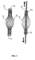
- a braided tool 52 is provided substantially in the shape of a braid 10 to be produced and the braid 10 is produced by braiding the braided tool 52. Since the braid 10 after completion is substantially closed, ie only has openings 14 at opposite ends and in its central portion has a bulbous portion 16 of larger diameter, wherein the diameter of the bulbous portion 16 is greater than the diameter of the openings 14 , Thus, the bulbous portion 16 forms an undercut to prevent the removal of the tool 52.
- Such a braided tool 52 may be reused in some circumstances when the reduction in area for removal of the tool 52 from the braid 10 takes place in the elastic region, i. the braided tool 52 returns to the original shape with the bulbous portion 16 when the pulling force on the ends of the tool 52 is removed.
- the braided tool 52 may be a single-use tool if the deformation is outside the elastic range, so that the original shape with the bulbous portion 16 can not be accepted by the braided tool 52.
- Such a tool 52 which can be applied even in areas of undercuts and can be removed by a cross-sectional reduction of the finished braid 10, can also in other shapes a mesh 10 are used.
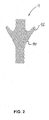
- FIG. 2 An example of this is in FIG. 2 shown in which a body implant 10 is made of a braid 10 having a pair of branches with an undercut 12. In this way, many complex shapes of a body implant can be produced. It can thus be provided a so-called personalized braid for a patient.
- the invention is not limited to the application of a braided tool 52, but can also be performed with tools that can be dissolved, for example, by heat.
- tools that can be dissolved, for example, by heat.
- examples include wax, resin and plastics such as polyphenyl alcohol.
- a tool can be removed from the undercuts 12 or a bulbous region 16 by dissolving the tool. For this purpose, for example, heat is applied to bring the tool to melt or dissolve.
- Another way to remove the tool from a manufactured mesh 10 is to break the tool, dissolve and / or provided with a predetermined breaking point.
- a reusable braiding tool 54 is used to make a braid 10.
- the reusable tool 54 is removed from the braid 10 and replaced with a disposable tool 56, as in FIG FIG. 4 is shown. Thereafter, the braiding process is completed and the finished braid 10 is in FIG. 5 shown.
- the disposable tool 56 can then be removed from the finished braid 10 by reducing its cross-section, as in FIG FIG. 1 is shown, or the disposable tool 56 is removed by melting, breaking or dissolution of the braid 10.
- the reference numeral 30 shows a known braiding machine with bobbins 35 for producing the braid 10.
- the method described above can also be used with that in the patent DE 10 2012 016 301 B3 described method for producing a body implant, as in FIG. 6 is shown.
- part of the braid 10 is removed and replaced by a second braid 10a, as in FIG. 6c is shown.
- the method described above is therefore particularly suitable for producing a vascular prosthesis, stent graft, occluder, flow diverter, coil, heart valve frame, AAA stent, TAA stent, gastroenterological stent or peripheral stent.
- the braids 10 of a body implant 1 can be made very flexible according to the method described above, complex and desired shapes for creating a personalized mesh 10 for a patient can be easily produced.
- the shaping of the braid 10 is preferably carried out by a heat treatment in order to reduce or substantially eliminate stresses arising in the braid 10.
- a shape memory property which is used in particular on the material Nitinol.
- a metal structure in a so-called martensite structure is provided in the braid 10, which is converted into an austenite structure by raising the temperature by phase transformation. It is extraordinary for Nitinol that this transformation is reversible without plastic defects occurring. The phase transformation thus takes place without diffusion, that is, without the atoms changing places in the lattice structure.
- the atoms adopt an ordered twin arrangement through pure shear deformation.
- tungsten can increase the radiopacity of the body implant 1.
- markers can increase the radiopacity, which are made of tantalum or gold, for example.
Landscapes
- Engineering & Computer Science (AREA)
- Textile Engineering (AREA)
- Manufacturing & Machinery (AREA)
- Prostheses (AREA)
Abstract
Description
- Die vorliegende Erfindung betrifft ein Verfahren zur Herstellung eines Körperimplantats, wie beispielsweise eines Stents, eines Herzklappenrahmens, eines Flow Diverter etc, zum Einsetzen in den lebenden Körper. Des weiteren betrifft die Erfindung ein Werkzeug zum Herstellen eines Körperimplantats.
- Körperimplantate, die beispielsweise aus einem Geflecht aus Nitinol gefertigt werden, sind in der Regel zylindrisch oder konisch oder eine Kombination aus beidem. Bedingt durch Randbedingungen wie z.B. Flechtwinkel, Drahtanzahl und Geometrie des Geflechts sowie die erforderlichen Formgebungsprozesse, ist die Variationsmöglichkeit eingeschränkt.
- Herkömmlich können komplexere Formen von Geflechten nur durch aufwändige Flechtalgorithmen oder durch Kompromisse in den Flechtwinkeln hergestellt werden, da es oftmals nicht möglich ist, verjüngte Durchmesser so weit aufzudehnen, dass eine beschädigungsfreies Separieren von Geflecht und Werkzeug möglich ist. Es wäre wünschenswert, wenn die Gestaltung der Geflechte mit höherer Flexibilität durchgeführt werden könnte.
- Die Aufgabe der Erfindung besteht in der Bereitstellung eines neuartigen Verfahrens zum Herstellen eines Körperimplantats, mit dem flexiblere Formen von Geflechten erzeugt werden können.
- Diese Aufgabe wird durch die Merkmale der unabhängigen Ansprüche gelöst. Vorteilhafte Weiterbildungen der Erfindung sind in den abhängigen Ansprüchen definiert.
- Gemäß einem Aspekt wird ein Verfahren zum Herstellen eines Körperimplantats mit folgenden Schritten zur Verfügung gestellt:
- Bereitstellen eines Werkzeugs mit einer vorgegebenen oder vorgebbaren Gestalt,
- Umflechten des Werkzeugs mit zumindest einem Flechtmaterial und dadurch Erzeugen eines Geflechts zumindest teilweise in der Gestalt des Werkzeugs,
- Durchführen einer Formgebung an dem Geflecht, und
- Entfernen des Werkzeugs von dem Geflecht, wobei das Werkzeug derart konfiguriert ist, dass die Gestalt des Werkzeugs (zumindest teilweise derart veränderbar ist, dass das Werkzeug entfernt werden kann, wenn das Geflecht im wesentlichen geschlossen ist und/oder das Geflecht das Werkzeug zumindest teilweise umhüllt und/oder Hinterschneidungen aufweist.
- Es handelt sich somit um ein Verfahren mit den Schritten:
- o Erzeugen eines Geflechts auf einem beliebig geformten Werkzeug,
- o Durchführen einer geeigneten Formgebung des Geflechts, und
- o Separieren des Geflechts vom Werkzeuges.
- Somit kann beispielsweise ein Geflecht mit wechselnden Durchmessern bei flexibel wählbarem Flechtwinkel und Drahtanzahl erzeugt werden. Das erzeugte Körperimplantat kann damit optimal auf die Anforderung bzw. die Anwendung abgestimmt werden. Es kann somit in verschiedenen Bereichen der Medizintechnik ein auf den individuellen Patienten optimiertes Körperimplantat, ein sogenanntes "personalisiertes Geflecht", hergestellt werden.
- Unter dem Begriff "Erzeugen eines Geflechts" ist insbesondere die maschinelle als auch die manuelle Herstellung eines Geflechts, in der Regel ein Umflechten zu verstehen.
- Unter Durchführen der Formgebung ist ein Abbauen der Spannungen zu verstehen, die infolge des Flechtprozesses entstanden sind. Sind alle Spannungen abgebaut, behält das Geflecht im wesentlichen seine Form. Beispielsweise ist für Nitinol die Formgebung typischer Weise als Wärmebehandlung zu verstehen.
- Unter dem Begriff "Separieren bzw. Entfernen des Geflechts vom Werkzeugs" ist insbesondere zu verstehen, dass das Werkzeug vom Geflecht getrennt wird. Ein Entfernen kann vorzugsweise durch Aufschmelzen infolge Wärmezufuhr, Zerbrechen, Auflösen in bzw. durch geeignete chemische Stoffe, auch Wasser sowie durch Umformen des Werkzeugs erfolgen. Das Werkzeug wird dadurch mindestens beschädigt und kann in der Regel nicht wiederverwendet werden. Man spricht in diesem Zusammenhang von einem einmalig verwendbaren Werkzeug oder vom Prinzip einer "verlorenen Form".
- Vorzugsweise wird der Schritt des Entfernen des Werkzeugs im wesentlichen gleichzeitig mit der Formgebung an dem Geflecht durchgeführt. Dies ist insbesondere vorteilhaft, wenn die Formgebung durch eine Wärmebehandlung durchgeführt wird und die Wärmezufuhr die Gestalt des Werkzeugs verändern kann.
- Weiter bevorzugt wird die Gestalt des Werkzeugs geändert, indem das Werkzeug beispielsweise schmilzt, bricht oder sich auflöst.
- Vorteilhaft sind Werkzeuge, die sich im Verlauf des Formgebungsprozesses beispielweise auf Grund hoher Temperaturen oder Temperaturunterschiede selbst zerstören. Die Zerstörung darf in diesem Fall erst nach erfolgter Formgebung erfolgen bzw. der formgebende Prozess soll entsprechend geplant ablaufen.
- Weiter bevorzugt weist das Werkzeug zumindest eine Sollbruchstelle auf.
- Vorzugsweise weist das Werkzeug zumindest eines aus einem Wachs, Harz, Kunststoff, wie beispielsweise Polyvinylalkohol, Schaum, Elastomer, glasfaserverstärkten Kunststoff, Zellstoff, Gips, Salz, Zucker, Klebstoff, Glas, Sand auf. Geeignet für eine Selbstzerstörung können beispielsweise Glas, Salze und Sandverbindungen sein.
- Weiter bevorzugt beinhaltet die Formgebung an dem Geflecht eine Wärmebehandlung.
- Weiter bevorzugt wird das Geflecht nach der Formgebung zumindest teilweise entflochten, um das Werkzeug durch ein anderes leicht auflösbares und/oder leicht entfernbares Werkzeug zu ersetzen, und das Geflecht anschließend wieder im wesentlichen in derselben Art geflochten wird und/oder durch ein anderes Flechtmaterial ersetzt wird.
- Vorzugsweise weist das Werkzeug einen zerstörbaren Abschnitt und einen nicht zerstörbaren Abschnitt auf.
- Vorzugsweise weist das Werkzeug eine wiederverwendbare Hülle auf, die zur Herstellung der gewünschten Form des Werkzeugs mit einem Fluid gefüllt werden kann und zum Entfernen zumindest teilweise entleert wird.
- Wiederverwendbare Werkzeuge können beispielsweise Hüllen sein, die beim Entfernen des Werkzeugs entleert werden und bei einem nächsten herzustellenden Geflecht wieder gefüllt werden können. Es können aber auch wiederverwendbare Werkzeuge in der Gestalt eines Geflechts oder eines Gebildes ähnlich einem Geflecht strukturiert als Werkzeug Anwendung finden. In diesem Fall erfolgt das Separieren durch ein Abziehen oder Herausziehen, wobei vorzugsweise ein Querschnitt des Werkzeugs verringert wird.
- Nitinol oder andere gängige metallische Drahtmaterialien könnten für wiederverwendbare Werkzeuge eingesetzt werden. Für sogenannte Hüllen können alle flexiblen und dünnwandig ausführbaren Werkstoffe Verwendung finden, die dem jeweiligen Formgebungsprozess widerstehen können.
- Weiter bevorzugt ist das Werkzeug zumindest teilweise als Geflecht oder geflechtartige Struktur ausgebildet und wird zum Entfernen auf Zug beansprucht, um den Querschnitt so zu verringern, dass ein Entfernen ermöglicht wird.
- Als vorteilhafte Weiterentwicklung kann je nach Material, Form bzw. Komplexität des Geflechts und der damit verbundenen Behandlungsmethode ein Öffnen des Geflechts erforderlich werden. Beispielsweise könnte es sich hierbei um sehr feine Strukturen handeln, die das Verwenden bestimmter Werkzeugmaterialien ausschließen und damit nicht direkt auf dem "verlorene Form" Werkzeug geflochten werden können.
- In diesem Fall kann das Geflecht geöffnet werden, um das ursprüngliche Werkzeug durch ein anderes im wesentlichen formgleiches Werkzeug zu ersetzen. Dabei kann das andere (zweite) Werkzeug aus einem Material oder mehreren Materialien bestehen, die beispielsweise chemisch auflösbar sind und/oder durch geringe Wärmezufuhr schmelzbar oder umformbar sind. Eine Beeinflussung oder Beeinträchtigung des geformten Geflechts muss jedoch vermieden werden.
- Unter dem Begriff "Öffnen" ist insbesondere zu verstehen, dass das Geflecht wieder entflochten wird. Ein "Öffnen" kann als Umkehrung bzw. inverser Vorgang zum Erzeugen eines Geflechts verstanden werden. Beispielsweise kann eine Textilstruktur/Geflecht durch Rückwärtsflechten geöffnet werden.
- Vorzugsweise wird bei einem Öffnen das Flechtmaterial bzw. der Nitinoldraht "in Position gehalten". Beispielsweise können Enden mittels Haltevorrichtungen, wie Greifern oder Draht fixiert werden, so dass lediglich der vorherige Flechtvorgang, nämlich das Erzeugen des Geflechts umgekehrt bzw. rückgängig gemacht wird. Das Geflecht wird dabei nur so weit geöffnet, bis es möglich ist, den Teil des Werkzeugs zu entfernen, der bei einem nicht geöffneten Geflecht, nicht zu entfernen wäre.
- Sollte die direkte Erzeugung des Geflechts eine mindestens zweite Formgebung erfordern, kann das Prinzip der "verlorenen Form" ebenfalls auf weitere formgebende Prozesse Anwendung finden. Ein Beispiel für die Notwendigkeit wäre das Erzeugen von Hinterschnitten. Idealerweise kommen hierbei Kombinationswerkzeuge zum Einsatz, die aus einem zerstörbaren und einem haltbaren wiederverwendbaren Teil bestehen, wobei der haltbare Teil vorzugsweise die erforderliche End- oder Zwischenform vorgibt.
- Weiter bevorzugt weist das Werkzeug zumindest einen mechanisch verlagerbaren Bereich auf, der durch Umklappen, Schwenken, Drehen etc. mechanisch verlagerbar ist, um die Gestalt des Werkzeugs zu verändern.
- Vorzugsweise wird durch das vorstehend beschriebene Verfahren eine Gefäßprothese, ein Stentgraft, ein Okkluder, ein Flow Diverter, ein Coil, ein Herzklappenrahmen, ein AAA Stent, ein TAA Stent (Thoracic Aortic Aneurysm), ein gastronenterologischer Stent oder ein peripherer Stent hergestellt. Als Bauchaortenaneurysma (BAA), abdominales Aortenaneurysma (AAA) oder Aneurysma verum Aortae abdominalis wird eine Erweiterung der abdominalen Aorta unterhalb des Abgangs der Nierenarterien im anterioposterioren Durchmesser auf über 30 mm angesehen. Klinisch unterscheidet man zwischen asymptomatischen, symptomatischen und rupturierten Aneurysmata. Beim asymptomatischen (schmerzfreien) Aneurysma handelt es sich um einen Zufallsbefund. Beim symptomatischen Aneurysma stehen die Symptome und bei den rupturierten die Kreislaufsituation im Vordergrund.
- Gemäß einem weiteren Aspekt wird ein Werkzeug zum Herstellen eines Körperimplantats durch zumindest teilweises Umflechten des Werkzeugs zur Verfügung gestellt, wobei das Werkzeug eine Gestalt aufweist, die zumindest teilweise derart veränderbar ist, dass das Werkzeug entfernt werden kann, wenn ein durch Umflechten des Werkzeugs erzeugtes Geflecht im wesentlichen geschlossen ist und/oder das Geflecht das Werkzeug zumindest teilweise umhüllt und/oder Hinterschneidungen aufweist.
- Vorzugsweise ist die Gestalt des Werkzeugs veränderbar, indem das Werkzeug schmilzt, bricht und/oder sich auflöst und/oder das Werkzeug zumindest eine Sollbruchstelle aufweist.
- Weiter bevorzugt ist die Gestalt des Werkzeugs veränderbar, indem das Werkzeug eine wiederverwendbare Hülle aufweist, die zur Herstellung der gewünschten Form des Werkzeugs mit einem Fluid gefüllt werden kann und zum Entfernen zumindest teilweise entleert wird.
- Vorzugsweise ist das Werkzeug zumindest teilweise als Geflecht oder geflechtartige Struktur ausgebildet.
- Weiter bevorzugt weist das Werkzeug zumindest einen mechanisch verlagerbaren Bereich auf, der durch Umklappen, Schwenken, Drehen etc. mechanisch verlagerbar ist, um die Gestalt des Werkzeugs zu verändern.
- Die Erfindung wird nun anhand mehrerer Ausführungsbeispiele unter Bezugnahme auf die beigefügten Zeichnungen näher erläutert.
-
Figur 1 zeigt ein Geflecht, das mittels eines geflochtenen Werkzeugs hergestellt wird. -
Figur 2 zeigt ein aus einem Geflecht hergestelltes Körperimplantat mit Hinterschneidungen. -
Figur 3 zeigt das Erzeugen eines Geflechts durch Umflechten eines Werkzeugs und teilweises Rückwärtsflechten zum Entfernen des Werkzeugs. -
Figur 4 zeigt das Entfernen eines ersten Werkzeugs und Einsetzen eines anderen Werkzeugs in ein teilweise geöffnetes Geflecht. -
Figur 5 zeigt das Fertigstellen des Geflechts ausFigur 4 . -
Figur 6 zeigt das Erzeugen eines Geflechts und Durchführen einer Formgebung sowie das Einsetzen eines zweiten Geflechts in das erste Geflecht. - Wie in
Figur 1 gezeigt ist, wird ein geflochtenes Werkzeug 52 im wesentlichen in der Gestalt eines zu erzeugenden Geflechts 10 zur Verfügung gestellt und das Geflecht 10 durch Umflechten des geflochtenen Werkzeugs 52 erzeugt. Da das Geflecht 10 nach dem Fertigstellen im wesentlichen geschlossen ist, d.h. nur noch Öffnungen 14 an entgegengesetzten Enden aufweist und in seinem zentralen Abschnitt einen bauchigen Bereich 16 mit größerem Durchmesser aufweist, wobei der Durchmesser des bauchigen Bereichs 16 größer als der Durchmesser der Öffnungen 14 ist. Somit bildet der bauchige Bereich 16 eine Hinterschneidung, um das Entfernen des Werkzeugs 52 zu verhindern. - Um das geflochtene Werkzeug 52 aus dem fertiggestellten Geflecht 10 zu entfernen, wird auf die entgegengesetzten Enden des Werkzeugs 52 Zug ausgeübt, so dass sich das geflochtene Werkzeug 52 in seiner Länge dehnt und der Querschnitt verringert wird. Auf diese Weise wird, wie in
Figur 1 gezeigt ist, der Querschnitt des geflochtenen Werkzeugs 52 derart verringert, dass der Querschnitt kleiner als jener der Öffnungen 14 ist, um das Werkzeug 52 aus den Öffnungen 14 herausziehen zu können. - Ein derartiges geflochtenes Werkzeug 52 kann unter Umständen wiederverwendet werden, wenn die Querschnittsverringerung zum Entfernen des Werkzeugs 52 aus dem Geflecht 10 im elastischen Bereich stattfindet, d.h. das geflochtene Werkzeug 52 nimmt wieder die ursprüngliche Gestalt mit dem bauchigen Bereich 16 an, wenn die Zugkraft auf die Enden des Werkzeugs 52 weggenommen wird. Es kann sich bei dem geflochtenen Werkzeug 52 jedoch auch um ein nur einmal verwendbares Werkzeug handeln, wenn die Verformung außerhalb des elastischen Bereichs stattfindet, so dass die ursprüngliche Gestalt mit dem bauchigen Bereich 16 durch das geflochtene Werkzeug 52 nicht mehr angenommen werden kann.
- Ein derartiges Werkzeug 52, das selbst in Bereichen von Hinterschneidungen angewandt werden kann und durch eine Querschnittsverringerung aus dem fertig gestellten Geflecht 10 entnommen werden kann, kann auch bei anderen Gestalten eines Geflechts 10 zur Anwendung gelangen.
- Ein Beispiel hierfür ist in
Figur 2 gezeigt, in der ein Körperimplantat 10 aus einem Geflecht 10 hergestellt ist, das ein Paar Verzweigungen mit einer Hinterschneidung 12 aufweist. Auf diese Weise sind viele komplexe Gestalten eines Körperimplantats herstellbar. Es kann somit ein sogenanntes personalisiertes Geflecht für einen Patienten zur Verfügung gestellt werden. - Die Erfindung ist jedoch nicht auf die Anwendung eines geflochtenen Werkzeugs 52 beschränkt, sondern kann auch mit Werkzeugen durchgeführt werden, die sich beispielsweise durch Wärme auflösen lassen. Beispiele hierfür sind Wachs, Harz und Kunststoffe, wie beispielsweise Polyphenylalkohol. In diesem Fall kann ein Werkzeug aus den Hinterschneidungen 12 bzw. einem bauchigen Bereich 16 durch Auflösen des Werkzeugs entfernt werden. Hierzu wird beispielsweise Wärme angewandt, um das Werkzeug zum Schmelzen bzw. Auflösen zu bringen.
- Eine weitere Möglichkeit zum Entfernen des Werkzeugs aus einem hergestellten Geflecht 10 besteht darin, das Werkzeug zu brechen, aufzulösen und/oder mit einer Sollbruchstelle zu versehen.
- Die vorstehend beschriebene Art des Entfernens eines Werkzeugs aus einem fertig hergestellten Geflecht 10 durch Verringern des Querschnitts, Schmelzen, Brechen oder Auflösen nach dem Prinzip der verlorenen Form kann auch nach einem ersten Flechtvorgang und/oder nach einer ersten Formgebung und/oder Wärmebehandlung stattfinden. Hierzu wird, wie in den
Figuren 3 und4 gezeigt ist, zunächst ein wiederverwendbares Werkzeug 54 zum Umflechten angewandt, um ein Geflecht 10 herzustellen. - Nach dem Rückwärtsflechten bzw. teilweisen Öffnen des Geflechts 10 wird das wiederverwendbare Werkzeug 54 aus dem Geflecht 10 entnommen und durch ein einmalig verwendbares Werkzeug 56 ersetzt, wie in
Figur 4 gezeigt ist. Danach wird der Flechtvorgang fertiggestellt und das fertige Geflecht 10 ist inFigur 5 dargestellt. Das einmalig verwendbare Werkzeug 56 kann dann aus dem fertiggestellten Geflecht 10 entnommen werden, in dem sein Querschnitt verringert wird, wie inFigur 1 gezeigt ist, oder das einmalig verwendbare Werkzeug 56 durch Schmelzen, Brechen oder Auflösen aus dem Geflecht 10 entnommen wird. - In den
Figuren 3 bis 5 zeigt das Bezugszeichen 30 eine bekannte Flechtmaschine mit Klöppeln 35 zum Erzeugen des Geflechts 10. - Das vorstehend beschriebene Verfahren kann auch mit dem in dem Patent
DE 10 2012 016 301 B3 beschriebenen Verfahren zum Herstellen eines Körperimplantats kombiniert werden, wie inFigur 6 gezeigt ist. Dabei wird nach einer ersten Wärmebehandlung an einem ersten Geflecht 10 ein Teil des Geflechts 10 entfernt und durch ein zweites Geflecht 10a ersetzt, wie inFigur 6c gezeigt ist. - Das vorstehend beschriebene Verfahren eignet sich somit insbesondere zum Herstellen einer Gefäßprothese, eines Stentgrafts, eines Okkluders, eines Flow Diverters, einer Coil, eines Herzklappenrahmens, eines AAA-Stents, eines TAA-Stents, eines gastroenterologischen Stents oder eines peripheren Stents.
- Nachdem die Geflechte 10 eines Körperimplantats 1 nach dem vorstehend beschriebenen Verfahren sehr flexibel gestaltet werden können, können komplexe und gewünschte Gestalten zum Erzeugen eines für einen Patienten personalisierten Geflechts 10 auf einfache Weise hergestellt werden. Die Formgebung des Geflechts 10 wird vorzugsweise durch eine Wärmebehandlung durchgeführt, um in dem Geflecht 10 entstandene Spannungen abzubauen oder im wesentlichen zu eliminieren.
- Es kann jedoch auch eine Formgedächtniseigenschaft angewandt werden, die insbesondere an dem Werkstoff Nitinol angewandt wird. Dabei wird ein Metallgefüge in einer sogenannten Martensitstruktur in dem Geflecht 10 zur Verfügung gestellt, das durch Erhöhen der Temperatur durch Phasenumwandlung in eine Austenitstruktur umgewandelt wird. Dabei ist es für Nitinol außergewöhnlich, dass diese Umwandlung reversibel ist, ohne dass plastische Defekte auftreten. Die Phasenumwandlung findet somit diffusionslos statt, das heißt, ohne dass die Atome ihre Plätze in der Gitterstruktur wechseln. Insbesondere nehmen bei dieser diffusionslosen reversiblen Phasenumwandlung des Austenit- in die Martensitstruktur die Atome durch reine Scherdeformation eine geordnete Zwillingsanordnung ein.
- Anstelle von Nitinol kann jedoch auch ein Polymer, ein bioabbaubares Polymer oder Wolfram verwendet werden. Dabei kann Wolfram die Röntgensichtbarkeit des Körperimplantats 1 erhöhen. Es können jedoch auch sogenannte Marker die Röntgensichtbarkeit erhöhen, die beispielsweise aus Tantal oder Gold hergestellt sind.
-
- 1
- Körperimplantat
- 10, 10a
- Geflecht
- 12
- Hinterschneidung
- 14
- Öffnung
- 16
- bauchiger Bereich
- 30
- Flechtmaschine
- 35
- Klöppel
- 52
- geflochtenes Werkzeug
- 54
- wiederverwendbares Werkzeug
- 56
- einmalig verwendbares Werkzeug
Claims (15)
- Verfahren zum Herstellen eines Körperimplantats mit den Schritten:Bereitstellen eines Werkzeugs (52; 54; 56) mit einer vorgegebenen oder vorgebbaren Gestalt,Umflechten des Werkzeugs (52; 54; 56) mit zumindest einem Flechtmaterial und dadurch Erzeugen eines Geflechts (10, 10a) zumindest teilweise in der Gestalt des Werkzeugs (52; 54; 56),Durchführen einer Formgebung an dem Geflecht (10), undEntfernen des Werkzeugs (52; 54; 56) von dem Geflecht (10, 10a), wobei das Werkzeug (52; 54; 56) derart konfiguriert ist, dass die Gestalt des Werkzeugs (52; 54; 56) zumindest teilweise derart veränderbar ist, dass das Werkzeug (52; 54; 56) entfernt werden kann, wenn das Geflecht (10, 10a) im wesentlichen geschlossen ist und/oder das Geflecht (10, 10a) das Werkzeug (52; 54; 56) zumindest teilweise umhüllt und/oder Hinterschneidungen (12) aufweist.
- Verfahren nach Anspruch 1, wobei der Schritt des Entfernen des Werkzeugs (52; 54; 56) im wesentlichen gleichzeitig mit der Formgebung an dem Geflecht (10) durchgeführt wird.
- Verfahren nach einem der vorherigen Ansprüche, wobei die Gestalt des Werkzeugs (56) geändert wird, indem das Werkzeug (56) schmilzt, bricht und/oder sich auflöst und/oder das Werkzeug (56) zumindest eine Sollbruchstelle aufweist.
- Verfahren nach einem der vorherigen Ansprüche, wobei das Werkzeug (52; 54; 56) zumindest eines aus einem Wachs, Harz, Kunststoff bevorzugt Polyvinylalkohol, Schaum, Elastomer, glasfaserverstärkten Kunststoff, Zellstoff, Gips, Salz, Zucker, Klebstoff, Glas, Sand aufweist.
- Verfahren nach einem der vorherigen Ansprüche, wobei die Formgebung an dem Geflecht (10) eine Wärmebehandlung beinhaltet.
- Verfahren nach einem der vorherigen Ansprüche, wobei das Geflecht (10) nach der Formgebung zumindest teilweise entflochten wird, um das Werkzeug (54) durch ein anderes leicht auflösbares und/oder leicht entfernbares Werkzeug (52, 56) zu ersetzen, und das Geflecht (10) anschließend wieder im wesentlichen in derselben Art geflochten wird und/oder durch ein anderes Flechtmaterial (10a) ersetzt wird.
- Verfahren nach einem der vorherigen Ansprüche, wobei das Werkzeug (52; 54; 56) einen zerstörbaren Abschnitt und einen nicht zerstörbaren Abschnitt aufweist.
- Verfahren nach einem der vorherigen Ansprüche, wobei das Werkzeug (54) eine wiederverwendbare Hülle aufweist, die zur Herstellung der gewünschten Form des Werkzeugs mit einem Fluid gefüllt werden kann und zum Entfernen zumindest teilweise entleert wird.
- Verfahren nach einem der vorherigen Ansprüche, wobei das Werkzeug (52) zumindest teilweise als Geflecht oder geflechtartige Struktur ausgebildet ist und das Werkzeug (52) zum Entfernen auf Zug beansprucht wird, um den Querschnitt so zu verringern, dass ein Entfernen ermöglicht wird.
- Verfahren nach einem der vorherigen Ansprüche, wobei das Werkzeug (52; 54; 56) zumindest einen mechanisch verlagerbaren Bereich aufweist, der durch Umklappen, Schwenken, Drehen etc. mechanisch verlagerbar ist, um die Gestalt des Werkzeugs (52; 54; 56) zu verändern.
- Verfahren nach einem der vorherigen Ansprüche, wobei eine Gefäßprothese, ein Stentgraft, ein Okkluder, ein Flow Diverter, ein Coil, ein Herzklappenrahmen, ein AAA Stent, ein TAA Stent, ein gastronenterologischer Stent oder ein peripherer Stent hergestellt wird.
- Werkzeug zum Herstellen eines Körperimplantats durch zumindest teilweises Umflechten des Werkzeugs (52; 54; 56), wobei das Werkzeug (52; 54; 56) eine Gestalt aufweist, die zumindest teilweise derart veränderbar ist, dass das Werkzeug (52; 54; 56) entfernt werden kann, wenn ein durch Umflechten des Werkzeugs (52; 54; 56) erzeugtes Geflecht (10, 10a) im wesentlichen geschlossen ist und/oder das Geflecht (10, 10a) das Werkzeug (52; 54; 56) zumindest teilweise umhüllt und/oder Hinterschneidungen (12) aufweist.
- Werkzeug nach Anspruch 12, wobei die Gestalt des Werkzeugs (56) veränderbar ist, indem das Werkzeug (56) schmilzt, bricht und/oder sich auflöst und/oder das Werkzeug (56) zumindest eine Sollbruchstelle aufweist.
- Werkzeug nach Anspruch 12, wobei die Gestalt des Werkzeugs (56) veränderbar ist, indem das Werkzeug (54) eine wiederverwendbare Hülle aufweist, die zur Herstellung der gewünschten Form des Werkzeugs mit einem Fluid gefüllt werden kann und zum Entfernen zumindest teilweise entleert wird.
- Werkzeug nach Anspruch 12, das zumindest teilweise als Geflecht oder geflechtartige Struktur ausgebildet ist und/oder zumindest einen mechanisch verlagerbaren Bereich aufweist, der durch Umklappen, Schwenken, Drehen etc. mechanisch verlagerbar ist, um die Gestalt des Werkzeugs (52; 54; 56) zu verändern.
Applications Claiming Priority (1)
| Application Number | Priority Date | Filing Date | Title |
|---|---|---|---|
| DE102014009920.2A DE102014009920B4 (de) | 2014-07-03 | 2014-07-03 | Verfahren zur Herstellung eines Körperimplantats und Werkzeug hierfür |
Publications (2)
| Publication Number | Publication Date |
|---|---|
| EP2977496A1 true EP2977496A1 (de) | 2016-01-27 |
| EP2977496B1 EP2977496B1 (de) | 2019-07-17 |
Family
ID=53365696
Family Applications (1)
| Application Number | Title | Priority Date | Filing Date |
|---|---|---|---|
| EP15001570.9A Active EP2977496B1 (de) | 2014-07-03 | 2015-05-22 | Verfahren zur herstellung eines körperimplantats und werkzeug hierfür |
Country Status (3)
| Country | Link |
|---|---|
| EP (1) | EP2977496B1 (de) |
| DE (1) | DE102014009920B4 (de) |
| ES (1) | ES2749004T3 (de) |
Cited By (1)
| Publication number | Priority date | Publication date | Assignee | Title |
|---|---|---|---|---|
| EP3964617A1 (de) * | 2020-09-03 | 2022-03-09 | ADMEDES GmbH | Computer-gestütztes verfahren zum erstellen eines flechtprogramms, computerprogramm zum erstellen eines flechtprogramms, flechtprogramm und vorrichtung zum erstellen eines flechtprogramms |
Citations (4)
| Publication number | Priority date | Publication date | Assignee | Title |
|---|---|---|---|---|
| US3586058A (en) * | 1968-09-25 | 1971-06-22 | Mc Donnell Douglas Corp | Hollow bodies and method of fabricating the same |
| WO1995017997A2 (en) * | 1993-12-20 | 1995-07-06 | Goodwin Stephen L | Molded products made from preforms of tubular braids |
| US20040254633A1 (en) * | 2003-06-10 | 2004-12-16 | Avraham Rapaport | Method and apparatus for making intraluminal implants and construction particularly useful in such method and apparatus |
| DE102012016301B3 (de) | 2012-08-16 | 2013-12-12 | Admedes Schuessler Gmbh | Verfahren zum Herstellen eines Körperimplantats |
Family Cites Families (5)
| Publication number | Priority date | Publication date | Assignee | Title |
|---|---|---|---|---|
| US7364587B2 (en) * | 2004-09-10 | 2008-04-29 | Scimed Life Systems, Inc. | High stretch, low dilation knit prosthetic device and method for making the same |
| WO2006034150A2 (en) * | 2004-09-17 | 2006-03-30 | Cordis Neurovascular, Inc. | Vascular occlusion device with an embolic mesh ribbon |
| CA2785989A1 (en) * | 2009-12-31 | 2011-07-07 | Neograft Technologies, Inc. | Graft devices and methods of fabrication |
| US9867690B2 (en) * | 2011-02-09 | 2018-01-16 | Neograft Technologies, Inc. | System and mandrel for creating graft devices |
| AU2012366236B2 (en) * | 2012-01-17 | 2017-10-12 | Artio Medical, Inc. | Expandable body device and method of use |
-
2014
- 2014-07-03 DE DE102014009920.2A patent/DE102014009920B4/de active Active
-
2015
- 2015-05-22 ES ES15001570T patent/ES2749004T3/es active Active
- 2015-05-22 EP EP15001570.9A patent/EP2977496B1/de active Active
Patent Citations (4)
| Publication number | Priority date | Publication date | Assignee | Title |
|---|---|---|---|---|
| US3586058A (en) * | 1968-09-25 | 1971-06-22 | Mc Donnell Douglas Corp | Hollow bodies and method of fabricating the same |
| WO1995017997A2 (en) * | 1993-12-20 | 1995-07-06 | Goodwin Stephen L | Molded products made from preforms of tubular braids |
| US20040254633A1 (en) * | 2003-06-10 | 2004-12-16 | Avraham Rapaport | Method and apparatus for making intraluminal implants and construction particularly useful in such method and apparatus |
| DE102012016301B3 (de) | 2012-08-16 | 2013-12-12 | Admedes Schuessler Gmbh | Verfahren zum Herstellen eines Körperimplantats |
Cited By (1)
| Publication number | Priority date | Publication date | Assignee | Title |
|---|---|---|---|---|
| EP3964617A1 (de) * | 2020-09-03 | 2022-03-09 | ADMEDES GmbH | Computer-gestütztes verfahren zum erstellen eines flechtprogramms, computerprogramm zum erstellen eines flechtprogramms, flechtprogramm und vorrichtung zum erstellen eines flechtprogramms |
Also Published As
| Publication number | Publication date |
|---|---|
| DE102014009920A1 (de) | 2016-01-07 |
| ES2749004T3 (es) | 2020-03-18 |
| DE102014009920B4 (de) | 2021-02-11 |
| EP2977496B1 (de) | 2019-07-17 |
Similar Documents
| Publication | Publication Date | Title |
|---|---|---|
| EP2698130B1 (de) | Verfahren zum Herstellen eines Körperimplantats | |
| EP1023008B1 (de) | Aufgeweiteter stent und verfahren zum herstellen desselben | |
| EP2995282B1 (de) | Vorgeformter stent | |
| DE69837062T2 (de) | Ballon-expandierbarer geflochtener Stent mit Rückhalteeinrichtung | |
| EP2613743B1 (de) | Implantat zur beeinflussung des blutflusses bei arteriovenösen fehlbildungen | |
| EP3764928B1 (de) | Thrombektomievorrichtung | |
| DE102014113836B4 (de) | Verfahren zum Herstellen eines patientenspezifischen, endovaskulären Implantats | |
| EP3041439B9 (de) | Einführ- und ablösesystem für implantate | |
| EP3380018A1 (de) | Bandförmiges okklusionsmittel | |
| WO2020239429A1 (de) | Satz von korrekturvorrichtungen zum durchführen einer kieferorthopädischen massnahme | |
| WO2019174991A1 (de) | Temporärer verschluss von aneurysmenhälsen | |
| EP2977496B1 (de) | Verfahren zur herstellung eines körperimplantats und werkzeug hierfür | |
| DE102007061931A1 (de) | Medizinisches Implantat | |
| WO2016192781A1 (de) | Occlusionsinstrument, bzw. occluder (verschlussvorrichtung) für herzdefekte und ihre herstellung | |
| DE10301850B4 (de) | Stent | |
| WO2023104590A1 (de) | Implantat zur behandlung von aneurysmen im bereich von bifurkationen | |
| DE102014006984A1 (de) | Occlusionsinstrument, bzw. Occluder (Verschlussvorrichtung) für Herzdefekte und ihre Herstellung | |
| DE102020115600A1 (de) | Implantat zur Behandlung von Aneurysmen | |
| DE10301600A1 (de) | Kombination von Stents | |
| EP2784200B1 (de) | Verfahren zur Herstellung eines patientenspezifischen Implantats und hergestelltes Implantat | |
| DE202013105452U1 (de) | System zum Verbinden eines medizinischen Implantats mit einer Einführhilfe | |
| DE102013103499A1 (de) | Flexibel gewebte anpassbare Hohlraumstütze | |
| EP3781088B1 (de) | Vorrichtung zur einbringung von implantaten | |
| WO2019197565A1 (de) | Verzweigter stent und stentsystem | |
| DE10114483A1 (de) | Katheterhybridstruktur und Herstellungsverfahren |
Legal Events
| Date | Code | Title | Description |
|---|---|---|---|
| PUAI | Public reference made under article 153(3) epc to a published international application that has entered the european phase |
Free format text: ORIGINAL CODE: 0009012 |
|
| AK | Designated contracting states |
Kind code of ref document: A1 Designated state(s): AL AT BE BG CH CY CZ DE DK EE ES FI FR GB GR HR HU IE IS IT LI LT LU LV MC MK MT NL NO PL PT RO RS SE SI SK SM TR |
|
| AX | Request for extension of the european patent |
Extension state: BA ME |
|
| 17P | Request for examination filed |
Effective date: 20160630 |
|
| RBV | Designated contracting states (corrected) |
Designated state(s): AL AT BE BG CH CY CZ DE DK EE ES FI FR GB GR HR HU IE IS IT LI LT LU LV MC MK MT NL NO PL PT RO RS SE SI SK SM TR |
|
| GRAP | Despatch of communication of intention to grant a patent |
Free format text: ORIGINAL CODE: EPIDOSNIGR1 |
|
| STAA | Information on the status of an ep patent application or granted ep patent |
Free format text: STATUS: GRANT OF PATENT IS INTENDED |
|
| RIC1 | Information provided on ipc code assigned before grant |
Ipc: D04C 1/06 20060101ALN20190123BHEP Ipc: D04C 3/48 20060101AFI20190123BHEP |
|
| RIC1 | Information provided on ipc code assigned before grant |
Ipc: D04C 1/06 20060101ALN20190129BHEP Ipc: D04C 3/48 20060101AFI20190129BHEP |
|
| INTG | Intention to grant announced |
Effective date: 20190219 |
|
| RIN1 | Information on inventor provided before grant (corrected) |
Inventor name: SCHERRIBLE, FRANK Inventor name: BUDILLON, FLORENT |
|
| GRAS | Grant fee paid |
Free format text: ORIGINAL CODE: EPIDOSNIGR3 |
|
| GRAA | (expected) grant |
Free format text: ORIGINAL CODE: 0009210 |
|
| STAA | Information on the status of an ep patent application or granted ep patent |
Free format text: STATUS: THE PATENT HAS BEEN GRANTED |
|
| AK | Designated contracting states |
Kind code of ref document: B1 Designated state(s): AL AT BE BG CH CY CZ DE DK EE ES FI FR GB GR HR HU IE IS IT LI LT LU LV MC MK MT NL NO PL PT RO RS SE SI SK SM TR |
|
| REG | Reference to a national code |
Ref country code: GB Ref legal event code: FG4D Free format text: NOT ENGLISH |
|
| REG | Reference to a national code |
Ref country code: CH Ref legal event code: EP |
|
| REG | Reference to a national code |
Ref country code: DE Ref legal event code: R096 Ref document number: 502015009635 Country of ref document: DE |
|
| REG | Reference to a national code |
Ref country code: IE Ref legal event code: FG4D Free format text: LANGUAGE OF EP DOCUMENT: GERMAN |
|
| REG | Reference to a national code |
Ref country code: AT Ref legal event code: REF Ref document number: 1155924 Country of ref document: AT Kind code of ref document: T Effective date: 20190815 |
|
| REG | Reference to a national code |
Ref country code: CH Ref legal event code: NV Representative=s name: PATENTANWAELTE SCHAAD, BALASS, MENZL AND PARTN, CH |
|
| REG | Reference to a national code |
Ref country code: NL Ref legal event code: MP Effective date: 20190717 |
|
| REG | Reference to a national code |
Ref country code: LT Ref legal event code: MG4D |
|
| PG25 | Lapsed in a contracting state [announced via postgrant information from national office to epo] |
Ref country code: FI Free format text: LAPSE BECAUSE OF FAILURE TO SUBMIT A TRANSLATION OF THE DESCRIPTION OR TO PAY THE FEE WITHIN THE PRESCRIBED TIME-LIMIT Effective date: 20190717 Ref country code: HR Free format text: LAPSE BECAUSE OF FAILURE TO SUBMIT A TRANSLATION OF THE DESCRIPTION OR TO PAY THE FEE WITHIN THE PRESCRIBED TIME-LIMIT Effective date: 20190717 Ref country code: BG Free format text: LAPSE BECAUSE OF FAILURE TO SUBMIT A TRANSLATION OF THE DESCRIPTION OR TO PAY THE FEE WITHIN THE PRESCRIBED TIME-LIMIT Effective date: 20191017 Ref country code: NL Free format text: LAPSE BECAUSE OF FAILURE TO SUBMIT A TRANSLATION OF THE DESCRIPTION OR TO PAY THE FEE WITHIN THE PRESCRIBED TIME-LIMIT Effective date: 20190717 Ref country code: NO Free format text: LAPSE BECAUSE OF FAILURE TO SUBMIT A TRANSLATION OF THE DESCRIPTION OR TO PAY THE FEE WITHIN THE PRESCRIBED TIME-LIMIT Effective date: 20191017 Ref country code: SE Free format text: LAPSE BECAUSE OF FAILURE TO SUBMIT A TRANSLATION OF THE DESCRIPTION OR TO PAY THE FEE WITHIN THE PRESCRIBED TIME-LIMIT Effective date: 20190717 Ref country code: PT Free format text: LAPSE BECAUSE OF FAILURE TO SUBMIT A TRANSLATION OF THE DESCRIPTION OR TO PAY THE FEE WITHIN THE PRESCRIBED TIME-LIMIT Effective date: 20191118 Ref country code: LT Free format text: LAPSE BECAUSE OF FAILURE TO SUBMIT A TRANSLATION OF THE DESCRIPTION OR TO PAY THE FEE WITHIN THE PRESCRIBED TIME-LIMIT Effective date: 20190717 |
|
| PG25 | Lapsed in a contracting state [announced via postgrant information from national office to epo] |
Ref country code: LV Free format text: LAPSE BECAUSE OF FAILURE TO SUBMIT A TRANSLATION OF THE DESCRIPTION OR TO PAY THE FEE WITHIN THE PRESCRIBED TIME-LIMIT Effective date: 20190717 Ref country code: AL Free format text: LAPSE BECAUSE OF FAILURE TO SUBMIT A TRANSLATION OF THE DESCRIPTION OR TO PAY THE FEE WITHIN THE PRESCRIBED TIME-LIMIT Effective date: 20190717 Ref country code: RS Free format text: LAPSE BECAUSE OF FAILURE TO SUBMIT A TRANSLATION OF THE DESCRIPTION OR TO PAY THE FEE WITHIN THE PRESCRIBED TIME-LIMIT Effective date: 20190717 Ref country code: IS Free format text: LAPSE BECAUSE OF FAILURE TO SUBMIT A TRANSLATION OF THE DESCRIPTION OR TO PAY THE FEE WITHIN THE PRESCRIBED TIME-LIMIT Effective date: 20191117 Ref country code: GR Free format text: LAPSE BECAUSE OF FAILURE TO SUBMIT A TRANSLATION OF THE DESCRIPTION OR TO PAY THE FEE WITHIN THE PRESCRIBED TIME-LIMIT Effective date: 20191018 |
|
| REG | Reference to a national code |
Ref country code: ES Ref legal event code: FG2A Ref document number: 2749004 Country of ref document: ES Kind code of ref document: T3 Effective date: 20200318 |
|
| PG25 | Lapsed in a contracting state [announced via postgrant information from national office to epo] |
Ref country code: TR Free format text: LAPSE BECAUSE OF FAILURE TO SUBMIT A TRANSLATION OF THE DESCRIPTION OR TO PAY THE FEE WITHIN THE PRESCRIBED TIME-LIMIT Effective date: 20190717 |
|
| PG25 | Lapsed in a contracting state [announced via postgrant information from national office to epo] |
Ref country code: PL Free format text: LAPSE BECAUSE OF FAILURE TO SUBMIT A TRANSLATION OF THE DESCRIPTION OR TO PAY THE FEE WITHIN THE PRESCRIBED TIME-LIMIT Effective date: 20190717 Ref country code: EE Free format text: LAPSE BECAUSE OF FAILURE TO SUBMIT A TRANSLATION OF THE DESCRIPTION OR TO PAY THE FEE WITHIN THE PRESCRIBED TIME-LIMIT Effective date: 20190717 Ref country code: RO Free format text: LAPSE BECAUSE OF FAILURE TO SUBMIT A TRANSLATION OF THE DESCRIPTION OR TO PAY THE FEE WITHIN THE PRESCRIBED TIME-LIMIT Effective date: 20190717 Ref country code: DK Free format text: LAPSE BECAUSE OF FAILURE TO SUBMIT A TRANSLATION OF THE DESCRIPTION OR TO PAY THE FEE WITHIN THE PRESCRIBED TIME-LIMIT Effective date: 20190717 |
|
| PG25 | Lapsed in a contracting state [announced via postgrant information from national office to epo] |
Ref country code: SK Free format text: LAPSE BECAUSE OF FAILURE TO SUBMIT A TRANSLATION OF THE DESCRIPTION OR TO PAY THE FEE WITHIN THE PRESCRIBED TIME-LIMIT Effective date: 20190717 Ref country code: IS Free format text: LAPSE BECAUSE OF FAILURE TO SUBMIT A TRANSLATION OF THE DESCRIPTION OR TO PAY THE FEE WITHIN THE PRESCRIBED TIME-LIMIT Effective date: 20200224 Ref country code: SM Free format text: LAPSE BECAUSE OF FAILURE TO SUBMIT A TRANSLATION OF THE DESCRIPTION OR TO PAY THE FEE WITHIN THE PRESCRIBED TIME-LIMIT Effective date: 20190717 |
|
| REG | Reference to a national code |
Ref country code: DE Ref legal event code: R097 Ref document number: 502015009635 Country of ref document: DE |
|
| PLBE | No opposition filed within time limit |
Free format text: ORIGINAL CODE: 0009261 |
|
| STAA | Information on the status of an ep patent application or granted ep patent |
Free format text: STATUS: NO OPPOSITION FILED WITHIN TIME LIMIT |
|
| PG2D | Information on lapse in contracting state deleted |
Ref country code: IS |
|
| 26N | No opposition filed |
Effective date: 20200603 |
|
| PG25 | Lapsed in a contracting state [announced via postgrant information from national office to epo] |
Ref country code: SI Free format text: LAPSE BECAUSE OF FAILURE TO SUBMIT A TRANSLATION OF THE DESCRIPTION OR TO PAY THE FEE WITHIN THE PRESCRIBED TIME-LIMIT Effective date: 20190717 |
|
| PG25 | Lapsed in a contracting state [announced via postgrant information from national office to epo] |
Ref country code: MC Free format text: LAPSE BECAUSE OF FAILURE TO SUBMIT A TRANSLATION OF THE DESCRIPTION OR TO PAY THE FEE WITHIN THE PRESCRIBED TIME-LIMIT Effective date: 20190717 |
|
| REG | Reference to a national code |
Ref country code: BE Ref legal event code: MM Effective date: 20200531 |
|
| PG25 | Lapsed in a contracting state [announced via postgrant information from national office to epo] |
Ref country code: LU Free format text: LAPSE BECAUSE OF NON-PAYMENT OF DUE FEES Effective date: 20200522 |
|
| PG25 | Lapsed in a contracting state [announced via postgrant information from national office to epo] |
Ref country code: BE Free format text: LAPSE BECAUSE OF NON-PAYMENT OF DUE FEES Effective date: 20200531 |
|
| REG | Reference to a national code |
Ref country code: AT Ref legal event code: MM01 Ref document number: 1155924 Country of ref document: AT Kind code of ref document: T Effective date: 20200522 |
|
| PG25 | Lapsed in a contracting state [announced via postgrant information from national office to epo] |
Ref country code: AT Free format text: LAPSE BECAUSE OF NON-PAYMENT OF DUE FEES Effective date: 20200522 |
|
| PG25 | Lapsed in a contracting state [announced via postgrant information from national office to epo] |
Ref country code: MT Free format text: LAPSE BECAUSE OF FAILURE TO SUBMIT A TRANSLATION OF THE DESCRIPTION OR TO PAY THE FEE WITHIN THE PRESCRIBED TIME-LIMIT Effective date: 20190717 Ref country code: CY Free format text: LAPSE BECAUSE OF FAILURE TO SUBMIT A TRANSLATION OF THE DESCRIPTION OR TO PAY THE FEE WITHIN THE PRESCRIBED TIME-LIMIT Effective date: 20190717 |
|
| PG25 | Lapsed in a contracting state [announced via postgrant information from national office to epo] |
Ref country code: MK Free format text: LAPSE BECAUSE OF FAILURE TO SUBMIT A TRANSLATION OF THE DESCRIPTION OR TO PAY THE FEE WITHIN THE PRESCRIBED TIME-LIMIT Effective date: 20190717 |
|
| PGFP | Annual fee paid to national office [announced via postgrant information from national office to epo] |
Ref country code: DE Payment date: 20250521 Year of fee payment: 11 |
|
| PGFP | Annual fee paid to national office [announced via postgrant information from national office to epo] |
Ref country code: ES Payment date: 20250616 Year of fee payment: 11 |
|
| PGFP | Annual fee paid to national office [announced via postgrant information from national office to epo] |
Ref country code: IT Payment date: 20250530 Year of fee payment: 11 |
|
| PGFP | Annual fee paid to national office [announced via postgrant information from national office to epo] |
Ref country code: FR Payment date: 20250527 Year of fee payment: 11 |
|
| PGFP | Annual fee paid to national office [announced via postgrant information from national office to epo] |
Ref country code: CH Payment date: 20250601 Year of fee payment: 11 |
|
| PGFP | Annual fee paid to national office [announced via postgrant information from national office to epo] |
Ref country code: CZ Payment date: 20250509 Year of fee payment: 11 |
|
| PGFP | Annual fee paid to national office [announced via postgrant information from national office to epo] |
Ref country code: IE Payment date: 20250521 Year of fee payment: 11 |
|
| PGFP | Annual fee paid to national office [announced via postgrant information from national office to epo] |
Ref country code: GB Payment date: 20260326 Year of fee payment: 12 |