EP2977325A1 - Machine de fermeture de coques à chargement latéral et procédé d'application d'une feuille - Google Patents
Machine de fermeture de coques à chargement latéral et procédé d'application d'une feuille Download PDFInfo
- Publication number
- EP2977325A1 EP2977325A1 EP14178630.1A EP14178630A EP2977325A1 EP 2977325 A1 EP2977325 A1 EP 2977325A1 EP 14178630 A EP14178630 A EP 14178630A EP 2977325 A1 EP2977325 A1 EP 2977325A1
- Authority
- EP
- European Patent Office
- Prior art keywords
- tray
- shell
- transfer
- transport device
- sealing
- Prior art date
- Legal status (The legal status is an assumption and is not a legal conclusion. Google has not performed a legal analysis and makes no representation as to the accuracy of the status listed.)
- Withdrawn
Links
Images


Classifications
-
- B—PERFORMING OPERATIONS; TRANSPORTING
- B65—CONVEYING; PACKING; STORING; HANDLING THIN OR FILAMENTARY MATERIAL
- B65B—MACHINES, APPARATUS OR DEVICES FOR, OR METHODS OF, PACKAGING ARTICLES OR MATERIALS; UNPACKING
- B65B7/00—Closing containers or receptacles after filling
- B65B7/16—Closing semi-rigid or rigid containers or receptacles not deformed by, or not taking-up shape of, contents, e.g. boxes or cartons
- B65B7/162—Closing semi-rigid or rigid containers or receptacles not deformed by, or not taking-up shape of, contents, e.g. boxes or cartons by feeding web material to securing means
- B65B7/164—Securing by heat-sealing
-
- B—PERFORMING OPERATIONS; TRANSPORTING
- B65—CONVEYING; PACKING; STORING; HANDLING THIN OR FILAMENTARY MATERIAL
- B65B—MACHINES, APPARATUS OR DEVICES FOR, OR METHODS OF, PACKAGING ARTICLES OR MATERIALS; UNPACKING
- B65B43/00—Forming, feeding, opening or setting-up containers or receptacles in association with packaging
- B65B43/42—Feeding or positioning bags, boxes, or cartons in the distended, opened, or set-up state; Feeding preformed rigid containers, e.g. tins, capsules, glass tubes, glasses, to the packaging position; Locating containers or receptacles at the filling position; Supporting containers or receptacles during the filling operation
- B65B43/48—Feeding or positioning bags, boxes, or cartons in the distended, opened, or set-up state; Feeding preformed rigid containers, e.g. tins, capsules, glass tubes, glasses, to the packaging position; Locating containers or receptacles at the filling position; Supporting containers or receptacles during the filling operation using reciprocating or oscillating pushers
-
- B—PERFORMING OPERATIONS; TRANSPORTING
- B65—CONVEYING; PACKING; STORING; HANDLING THIN OR FILAMENTARY MATERIAL
- B65B—MACHINES, APPARATUS OR DEVICES FOR, OR METHODS OF, PACKAGING ARTICLES OR MATERIALS; UNPACKING
- B65B43/00—Forming, feeding, opening or setting-up containers or receptacles in association with packaging
- B65B43/42—Feeding or positioning bags, boxes, or cartons in the distended, opened, or set-up state; Feeding preformed rigid containers, e.g. tins, capsules, glass tubes, glasses, to the packaging position; Locating containers or receptacles at the filling position; Supporting containers or receptacles during the filling operation
- B65B43/52—Feeding or positioning bags, boxes, or cartons in the distended, opened, or set-up state; Feeding preformed rigid containers, e.g. tins, capsules, glass tubes, glasses, to the packaging position; Locating containers or receptacles at the filling position; Supporting containers or receptacles during the filling operation using roller-ways or endless conveyors
Definitions
- the present invention relates to a method for applying a film to a tray according to the preamble of claim 1 and to a tray closing machine according to the preamble of claim 7.
- tray sealing machines also called tray sealers
- tray sealers are used, for example, in the packaging industry.
- the present invention can be used particularly well in the packaging of foods.
- From the DE 10 2008 030 510 A1 is a generic packaging machine for sealing or sealing a shell with a film known.
- a central component of the packaging machine disclosed there is a sealing station with a lower and an upper sealing tool, in which the actual sealing of the shell takes place with the film.
- the sealing station has a lifting system on which the trays to be sealed must be positioned.
- the feed belt and the discharge belt are collinear and operated in the same operating direction.
- the sealing station is collinear with the bands between one end of the feed belt and a beginning of the discharge belt.
- known sealing devices include a separate from the respective feed and Abstockedb skilledn tray receptacle (eg, the above-described lifting system of DE 10 2008 030 510 A1 ), on which the shells are located during the actual sealing process. This arrangement may necessitate a transfer of a shell to be sealed from the feed belt to the tray receptacle.
- a gripper system which grips shells located on the feed belt and, in the direction of the feed belt, moves further forward onto the lifting system of the sealing station. After completion of the sealing operation, the closed shells are brought by the gripper system of the lifting device of the sealing station further in the direction of feed belt (which is the same direction of the discharge belt) on the discharge conveyor, from where they can be removed.
- a gripper system is from the EP 0 424 226 B1 or the DE 10 2011 118 533 A1 discloses a feed system with transverse bars. Also in these systems, a cup receptacle of a sealing device is collinear between a supply and a discharge belt. Trays to be sealed on the feed belt are moved onto the tray receptacle of the sealing device with transverse bars whose longitudinal axis is perpendicular to the transport direction of the trays. The cross bars are linearly movable in the transport direction.
- the sealing process is not hindered by the cross bars in such a system, these are moved back after introduction of a shell in the sealing station against the transport direction until they are outside the sealing station, whereupon the actual sealing process can be initiated. After completion of the same sealed shells are moved by the corresponding cross bar further in the transport direction on the discharge conveyor.
- the packaging machine of DE 10 2004 023 474 A1 includes a stopper assembly for transferring the trays.
- a feed and a discharge are collinear and have a common direction.
- the trays are moved by the stopper assembly from the feed belt forward in the direction of movement of the feed belt to a receiving plate of a sealing device when the receiving plate is collinear between the belts.
- a transfer of a shell to be sealed from the conveyor belt to the receiving plate is thus also here in a linear movement in the common direction of the bands.
- the stopper arrangement comprises a plurality of stoppers arranged one behind the other in the running direction of the belts.
- the stoppers can be lowered in the vertical direction to stop each tray in a suitable position on the feed belt. Then the stoppers are moved in the direction of the bands and push so each one located in front of the corresponding stopper shell on the receiving plate. After transferring the bowls to the receiving plate the receiving plate is offset horizontally and vertically and so brought into a position in which can be sealed. The position of the shells on the receiving plate is not changed. After sealing, the receiving plate is returned to the original position and the sealed trays are moved in the common direction of the feeding and Abriosbands on the discharge conveyor. By moving the receiving plate after reacting the shells to be sealed on it should be possible to operate two receiving plates in a packaging machine simultaneously.
- At least some embodiments of the invention also fulfill the task of providing a space-saving tray sealing machine.
- the tray sealing machine according to claim 7 is adapted to perform the method according to claim 1.
- a tray to be provided with a film is brought into a transfer position along a feed direction by means of a first transport device.
- the shell is located on the first transport device.
- This transporting of the shell to the transfer position can advantageously be effected by means of a linear translational movement of the shell. This can be achieved for example by the use of one or more conveyor belts. It has proved to be particularly advantageous if the first transport device comprises two conveyor belts positioned one behind the other in the feed direction. Alternatively to one of the several Conveyor belts, the first transport device may also include one or more roller conveyors.
- the shell is transferred from the transfer position in a linear translational movement of the shell in a transfer direction to a shell receptacle of a sealing device.
- the direction of translation to the feed direction is vertical.
- both the transfer direction and the feed direction lie in a common plane, preferably a horizontal plane.
- the tray receptacle of the sealing device can be positioned in the transfer direction next to the conveyor belt.
- the film is applied to the shell by the sealing device.
- the shell receptacle of the sealing device may for this purpose correspond to a lower sealing tool, be part of a lower sealing tool or be arranged above a lower sealing tool.
- the shell receptacle may be moved in a vertical upward direction toward a second sealing tool.
- the tray receptacle is movable only in the vertical direction.
- the sealed shell can be removed again from the sealing device.
- a second transport device For transporting the sealed shells, a second transport device may be provided. Preferably, this is arranged such that the sealing device is located in the direction of transfer between the first and the second transport device.
- the sealed shell can be moved further in the direction of transfer from the shell receptacle to the second transporting device, preferably in a linear translational movement in the transferring direction.
- the sealed shell can then be transported away by means of the second transport device along a discharge from the sealing device.
- a second transport device preferably the first transport device with respect to the sealing device opposite, offers the advantage that the power of a working cycle can be increased. Since the transfer position of the first transport device does not have to be kept free during the sealing process, one or more new trays can already be brought from the first transport device in the feed direction to the transfer position during the sealing process.
- the discharge direction may, for example, be parallel (ie parallel and rectified) or antiparallel (ie parallel and in opposite directions) to the feed direction.
- the discharge direction is anti-parallel to the feed direction.
- the sealing device is in fact at an end position of the tray sealing machine.
- a transfer device is provided in the tray sealing machine according to the invention.
- This can comprise a first slider which is movable along the transfer direction, that is to say perpendicular to the feed direction and which is designed to push one (or more) shells (s) present on the first transport device, in particular at the transfer position, onto the tray receptacle, in particular in FIG a linear translation movement.
- the transfer device may comprise a second slider, which is also movable in the direction of translation or anti-parallel thereto.
- the second slider may be adapted to push a sealed cup from the tray receptacle.
- the second slider may be configured to push a sealed cup from the tray receptacle along the translation direction to the second transport device, preferably in a linear translational motion.
- the first slider can be driven by a chain drive. It is particularly advantageous if the first and the second slide can be driven by a common chain drive. Thus, the driving of the first and the second slider can be synchronized. It is also conceivable that the first and the second slider are synchronously driven by a mechanism other than a chain drive, for example via a transfer case.
- the chain drive such as a transfer case has the particular advantage that the first and the second slide are driven synchronously via a common drive source.
- the throughput of the tray sealing machine can be optimized in a simple manner.
- the accomplished by the second slide converting the sealed shells of the tray receiving the second transport device is carried out simultaneously with the conversion of other to be sealed shells from the transfer position of the first transport device on the tray receptacle.
- the first and / or the second slider is a rod with a longitudinal axis perpendicular to the direction of translation.
- the corresponding rod may be attached at its two ends in each case to a circumferential chain of a corresponding chain drive.
- the chain drive can have chains which are at least partially movable in the direction of translation and / or antiparallel thereto.
- the height of the slider can be adjusted over the first transport device.
- the feed direction and the transfer direction or the feed direction and the discharge direction or the transfer direction and the discharge direction or the feed direction, the transfer direction and the discharge direction are preferably in a common plane, preferably in a horizontal plane.
- the first and the second transport device or the first transport device and the shell receptacle or the shell receptacle and the second transport device or the first and the second transport device and the shell receptacle in a common plane, preferably in a horizontal plane.
- the shells may be disposed in the slide during shipment on the first transport, during sealing, and during discharge from the sealing device.
- the reaction of the shell may in each case include a sliding of the slide. This sliding can be done analogously to the direct sliding of the shells with the aid of the above-described first and second slide.
- the method according to the invention and the tray closing machine according to the invention allow an operating mode in which only one tray at a time is always transferred or sealed at the same time.
- the advantages of the invention are even more evident when several trays are simultaneously implemented and / or sealed to increase the power of a power stroke.
- the second transport device described above for the removal of the sealed trays is not provided. Instead the first transport device extends in the feed direction beyond the transfer position, preferably linear or curved.
- the sealed shell can be implemented in this simplified embodiment after completion of the sealing process of the shell receptacle back to the transfer position, preferably in a linear translational movement in anti-parallel to the Umsetzraum. From there, the sealed shell can be transported away by means of the first transport device along the feed direction of the sealing device. Also in this embodiment with extended first transport device, the transfer device can comprise a first slider movable along the transfer direction, which is designed to push one (or more) in the transfer position located shell (s) on the tray receptacle, in particular in a linear translational movement.
- the second slider of this embodiment may be configured to push one or more sealed shells from the tray receptacle anti-parallel to the direction of translation back to the transfer position on the first transport device.
- the slides can be designed as cross bars with a longitudinal axis running perpendicular to the direction of translation. Again, driving the slider over a chain drive is advantageous.
- the in the FIGS. 1 to 3 Sealing device 20 shown a Schalenversch usingmaschine 1 has a shell receptacle 22 in the form of a receiving plate.
- the shell receptacle 22 is configured differently.
- 22 recesses may be present in the tray receptacle, which at least partially receive the trays 2 to be sealed when they are positioned on the tray receptacle 22.
- the sealing device 20 may optionally be configured to form a closed chamber between a lower sealing tool 23 and an upper sealing tool 24 to seal the shells 2 under vacuum or modified atmosphere.
- the sealing device 20 also has the upper sealing tool 24 positioned over the cup receptacle 22.
- the tray receptacle 22 can be guided vertically upward toward the upper sealing tool 24 so as to seal the trays 2 between the tray receptacle 22 and the upper sealing tool 24 with the film 4, for example by heat welding or ultrasonic welding.
- Cutting devices can additionally be provided in the upper sealing tool 24 in order to sever the film 4 in the region of the edge of the shells 2.
- cup closing machines 1 have a first transport device 30.
- this comprises a first conveyor belt 34 and a second conveyor belt 32, which have a common conveying direction, the feed direction Z and are arranged in collinear succession therein.
- the second conveyor belt 32 comprises the transfer position. That is, located in the transfer position shells 2 are on the second conveyor belt 32.
- the second transport device 60 For removal of the sealed shells 2 in a discharge A show the FIGS. 1 and 2 a second transport device 60 of the tray sealing machine 1.
- the second transport device 60 similar to the first transport device 30 transport belts (or roller conveyors) include, for example, a first conveyor belt 62 and a second conveyor belt 64 which are arranged in the discharge direction A collinear one behind the other.
- the second transport device 60 is arranged on an opposite side of the sealing device 20 to the first transport device 30.
- the second transport device 60 is arranged on the opposite side in the transfer direction U of the first transport device 30 of the sealing device 20.
- the first conveyor belt 30, the tray receptacle 22 and the second conveyor belt 60 can be arranged one behind the other in the direction of transfer U.
- the transfer device 40 may have a first slider 42, which is movable in a translational translational movement in the direction U so that at the transfer position existing trays 2 to be sealed by the movement of the first slider 42 are pushed onto the tray receptacle 22.
- a second slider 44 may be arranged offset in the direction of conversion U to the first slider 42. By moving the second slider 44 in the direction of conversion U, the shells 2 can be pushed further onto the second transport device 60 after the sealing process by the shell receptacle 22. From there they can be transported away in discharge direction A.
- slide 42, 44 different embodiments conceivable. For example, it is possible to execute both slides 42, 44 as so-called pushers.
- the slides 42, 44 are formed as rods with a longitudinal axis which is perpendicular to the Umsetzraum U and parallel to the feed direction Z.
- both a movement of the first and second slider 42, 44 in the direction of conversion U as opposed to be realized in such a way that the slides 42, 44 move synchronously.
- a chain of the chain drive 46 can for this purpose run between the first conveyor belt 34 and the second conveyor belt 32 of the first transport device 30, advantageously at least partially or completely in the transfer direction U.
- the chain of the chain drive 46 running between the first and the second conveyor belt 34, 32 of the first transport device 30 can be located in a space between the first and the second transport belt 34 32 be lowered. That is, the chain in question in the vertical direction under the transport plane defined by the first and / or the second conveyor belt 34, 32.
- the transport plane comprises the area on which shells 2 to be transported by the conveyor belts 34, 32 are parked.
- the transport planes of the first and second conveyor belts 34, 32 are identical.
- the transport planes of the conveyor belts 34, 32 are horizontal planes.
- the sliders 42, 44 must be arranged above the transport plane of at least one conveyor belt 32, preferably parallel to the corresponding transport plane.
- This can be achieved by providing connecting pieces 52 between the lowered chain of the chain drive 46 and the respective sliders 42, 44.
- the connecting pieces 52 extend in a vertical upward direction and are secured to a chain of the chain drive 46 and to one end of a transverse rod forming a slider 42, 44.
- Each designed as a cross bar slide 42, 44 can at its two ends each connected to a connector 52 each having a chain of the chain drive 46.
- the chains, preferably two chains, run parallel to each other.
- the connecting pieces 52 may be formed, for example, rod-shaped. Bar-shaped is to be understood neither in connection with the slides 42, 44 nor in connection with the connecting pieces 52 as a restriction to a cross-sectional area of a particular shape.
- the cross-sectional area of the corresponding rod-shaped elements may be designed, for example, round, rectangular, pentagonal, hexagonal, octagonal or any other way. Due to the horizontal length of the connecting pieces 52, the height of the rod-shaped slide 42, 44 set above the first transport device 30.
- a vertical distance between a transport surface of the first transport device 30 or one of the conveyor belts 34, 32 thereof and the sliders 42, 44 can be selected. For example, vertical distances of 0.5 cm to 3 cm have been found to be advantageous.
- the chains of the chain drive 46 can also be lowered relative to the shell receptacle 22. That is, the chains in a vertical direction do not protrude beyond a surface of the tray receptacle 22 used to receive the trays 2.
- the shell receptacle 22 is provided between two parallel chains of the chain drive 46.
- a chain of the chain drive 46 can also extend between the first conveyor belt 62 and the second conveyor belt 64 of the second transport device 60, advantageously at least partially or completely in the direction of transfer U.
- one, several or all chains of the chain drive 46 can also be lowered relative to the second transport device 60.
- a corresponding chain can run between the first conveyor belt 62 and the second conveyor belt 64 of the second transport device 60, without protruding in a vertical direction over the transport surface.
- the chain drive 46 may comprise one or two chains circulating in a closed circle. As shown above, the invention can be realized with two slides 42, 44. In principle, an embodiment with only one slide 42 is also conceivable, which alternately pushes the shells from the transfer position onto the tray receptacle 22 and from the tray receptacle 22 onto the second transport device 60.
- a plurality of slides 42, 44, 48, 50 is provided on the common chain drive 46.
- the slides 42, 44, 48, 50 can preferably be provided as movable in the direction of movement U rods with a perpendicular to the Umsetzraum U longitudinal axis.
- the use of a plurality of slides 42, 44, 48, 50 (for example, more than 2, 3, 4, 5 or 10 slides) has the further advantage that no backward movement of the slide 42, 44, 48, 50 against the Umsetzraum U for Reacting the sealed shells 2 of the tray receptacle 22 is required.
- Each of the plurality of sliders 42, 44, 48, 50 executes in different operating situations optionally converting the shells 2 to be sealed from the transfer position to the shell receptacle 22 or the transfer of the sealed shells 2 from the shell receptacle 22 to the second transport device 60.
- the plurality of slides 42, 44, 48, 50 is at regular intervals in the direction of insertion U spaced from each other on the chain of the chain drive 46 is provided.
- the described, simple trained transfer device 40 of chain drive 46 and the at least two sliders 42, 44 allows multiple on the first transport device 30 (in the transfer position) existing to be sealed shells 2 at the same time to implement the shell receptacle 22 without changing their relative position to each other ,
- the fact that the Umsetzcardi U (in which the sliders 42, 44 are movable) is perpendicular to the feed direction Z, in the return movement of the slide 42, 44 against the Umsetzraum U does not hinder the transport of further shells 2 to the transfer position. This would be the case, for example, if the direction of translation U (and thus the movement of the slides 42, 44) were directed in the direction of the feed direction Z.
- the chain drive 46 is driven such that at least a portion of the plurality of slides 44, 46, 48, 50 in Implementing direction U is moved and so a slider 42, the shells 2 from the transfer position on the tray receptacle 22 pushes.
- the tray sealing machine 1 After the trays 2 are no longer returned to the first transport device 30 in such an embodiment, it is possible to refill the transfer position of the first transport device 30 already during the sealing process. As a result, the throughput of the tray sealing machine 1 can be further increased.
- a sufficient number of slides 44, 46, 48, 50 provided on the chain drive 46 so that they ensure a continuous loading of the sealing device 20 in an endless circulation of the chain drive 46.
- a further advantage of the method according to the invention and the tray sealing machine 1 according to the invention with a first and a second transport device 30, 60 is the high flexibility and adaptability to the place of use.
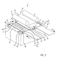
- the feed direction Z of the first transport device 30 and the discharge direction A of the second transport direction 60 are parallel to each other, they may also be antiparallel to each other. This is in FIG. 2 illustrated. In this way, it is possible to provide a very compact tray sealing machine 1. The application of the film 4 on a shell 2 can thus take place even in limited space.
- the feed direction Z of the first transport device 30 is at right angles to the discharge direction A of the second transport device 60.
- the first transport device 30 successively supplied trays 2 after sealing next to each other to transport.
- FIG. 3 shows an embodiment in which the shells 2 are received in a slide 100 during the sealing process. It can, as in FIG. 3 For example, seven trays 2 may be included in a slide 100. Alternatively, it is also possible that each shell 2 is received individually in a corresponding slide 100. Any other suitable number of trays 2 per slide 100 is conceivable.
- slides 100 may be useful, for example, if the shells 2 can not be transported in a stable position due to their shape. Even with very small shells 2, the use of slides 100 may be useful. Through the use of microscope slides 100 it can be ensured that the spatial position of the individual shells 2 relative to each other during the sealing process is as accurately as possible adjustable.
- the slides 100 may have openings 101 into which the trays 2 with the opening to be sealed are inserted upwardly. If microscope slides 100 are used, the shells 2 are moved onto the tray receptacle 22 by pushing the microscope slide 100 onto the tray receptacle 22. This sliding can take place analogously to the transfer of the trays 2 without slide 100, ie with one of the transfer devices 40 described above In principle, any of the embodiments of the invention described above can also be combined with the use of a slide 100 for the shells 2.
- FIG. 3 shows an embodiment of the invention Schalenversch separatemaschine 1, which is particularly well suited for use with slides 100.
- the omission of the slide 100 is also conceivable here.
- the tray sealing machine 1 comprises a first and a second transport device 30, 60.
- the transport devices 30, 60 are not shown for reasons of clarity, but their position can be seen from the illustration of the slides 100, 60 positioned on the transport devices 30, 60 and corresponds to FIG the first and the second transport device 30, 60 from FIG. 2 , Multi-lane and multi-row and freely defined (ie not only matrix-shaped) arrangements of shells 2 are also conceivable with microscope slides 100.
- FIG. 3 shows an embodiment in which the feed direction Z of the first transport device 30 and the discharge direction A of the second transport device 60 are anti-parallel.
- a cross-connection 102 between the two transport devices 30, 60 is provided, such that the first and the second transport device 30, 60 are connected in a U-shape.
- the transport devices 30, 60 and the cross-connection 102 are not shown or shown only schematically, their position can be revealed by the slides 100 lying thereon.
- the cross connection 102 may be a conveyor belt or a roller conveyor for manual onward transport.
- a removal device can be provided along the second transport device 60, which takes the sealed shells 2 out of the microscope slides 100.
- a filling station may be provided which inserts cups 2 to be sealed into the microscope slides 100.
- the tray sealing machine 1 may comprise a control device which controls the movement of the slides 42, 44, 48, 50, for example by the chain drive 46.
- the control device can control a transport speed of the first and / or second transport device 30, 60 control.
- the sealing device 20 can also be activated by the control device.
- the discharge of the sealed shells 2 takes place via the first transport device 30.
- the transfer device 40 may have at least two slides 42, 44.
- a first slider 42 is movable in translation direction U in a linear translational movement, such that shells 2 to be sealed at the transfer position are pushed onto the tray receptacle 22 by the movement of the first slider 42.
- a second slider 44 is arranged offset in the direction of U to the first slider 42. By moving the second slider 44 in anti-parallel to the transfer direction U, the shells 2 can be pushed back to the transfer position and thus to the first transport device 30 after the sealing operation of the shell receptacle 22. From there they can be further transported away in the feed direction Z via the first transport device 30 or its discharge part.
- the drive and the execution of the slides 42, 44 may be analogous to the embodiments described above.
Landscapes
- Engineering & Computer Science (AREA)
- Mechanical Engineering (AREA)
- Microelectronics & Electronic Packaging (AREA)
- Closing Of Containers (AREA)
Priority Applications (1)
| Application Number | Priority Date | Filing Date | Title |
|---|---|---|---|
| EP14178630.1A EP2977325A1 (fr) | 2014-07-25 | 2014-07-25 | Machine de fermeture de coques à chargement latéral et procédé d'application d'une feuille |
Applications Claiming Priority (1)
| Application Number | Priority Date | Filing Date | Title |
|---|---|---|---|
| EP14178630.1A EP2977325A1 (fr) | 2014-07-25 | 2014-07-25 | Machine de fermeture de coques à chargement latéral et procédé d'application d'une feuille |
Publications (1)
| Publication Number | Publication Date |
|---|---|
| EP2977325A1 true EP2977325A1 (fr) | 2016-01-27 |
Family
ID=51224830
Family Applications (1)
| Application Number | Title | Priority Date | Filing Date |
|---|---|---|---|
| EP14178630.1A Withdrawn EP2977325A1 (fr) | 2014-07-25 | 2014-07-25 | Machine de fermeture de coques à chargement latéral et procédé d'application d'une feuille |
Country Status (1)
| Country | Link |
|---|---|
| EP (1) | EP2977325A1 (fr) |
Cited By (3)
| Publication number | Priority date | Publication date | Assignee | Title |
|---|---|---|---|---|
| EP3272657A1 (fr) * | 2016-07-21 | 2018-01-24 | MULTIVAC Sepp Haggenmüller SE & Co. KG | Installation d'emballage |
| CN108788455A (zh) * | 2018-09-12 | 2018-11-13 | 苏州统硕科技有限公司 | 一种配合镭射刻印机使用的自动化设备 |
| CN114604618A (zh) * | 2022-03-04 | 2022-06-10 | 广东若铂智能机器人有限公司 | 一种新型取料装置 |
Citations (9)
| Publication number | Priority date | Publication date | Assignee | Title |
|---|---|---|---|---|
| EP0424226B1 (fr) | 1989-10-20 | 1993-09-22 | Mecaplastic | Machine de conditionnement assurant la fermeture de barquettes de conditionnement ou similaires après leur remplissage, et ce par soudure d'un film en matière thermoplastique |
| US6305149B1 (en) * | 1993-11-18 | 2001-10-23 | Marlen Research Corporation | Method and apparatus for packaging meat |
| WO2004056655A2 (fr) * | 2002-12-20 | 2004-07-08 | Sealed Air (Nz) Limited | Machine a emballer sous vide pour emballages de produits contenant de multiples produits |
| EP1577216A1 (fr) * | 2004-03-15 | 2005-09-21 | Reepack S.r.l. | Machine d'emballage et procédé d'emballage pour barquettes |
| EP1598273A1 (fr) * | 2004-05-12 | 2005-11-23 | Multivac Sepp Haggenmüller GmbH & Co. KG | Dispositif et procédé pour fermer des récipients |
| DE102008030510A1 (de) | 2008-06-27 | 2010-01-14 | Multivac Sepp Haggenmüller Gmbh & Co. Kg | Verpackungsmaschine mit einem Greifersystem |
| US20110072764A1 (en) * | 2009-09-30 | 2011-03-31 | Ross Industries, Inc. | Method and apparatus for sealing containers |
| DE102011118533A1 (de) | 2011-11-15 | 2013-05-16 | Multivac Sepp Haggenmüller Gmbh & Co. Kg | Schalenverschließmaschinen mit zwei Siegelstationen |
| EP2644517A2 (fr) * | 2012-03-30 | 2013-10-02 | Multivac Sepp Haggenmüller GmbH & Co. KG | Poste de scellage multirangées, machine à emballer et méthode correspondante |
-
2014
- 2014-07-25 EP EP14178630.1A patent/EP2977325A1/fr not_active Withdrawn
Patent Citations (10)
| Publication number | Priority date | Publication date | Assignee | Title |
|---|---|---|---|---|
| EP0424226B1 (fr) | 1989-10-20 | 1993-09-22 | Mecaplastic | Machine de conditionnement assurant la fermeture de barquettes de conditionnement ou similaires après leur remplissage, et ce par soudure d'un film en matière thermoplastique |
| US6305149B1 (en) * | 1993-11-18 | 2001-10-23 | Marlen Research Corporation | Method and apparatus for packaging meat |
| WO2004056655A2 (fr) * | 2002-12-20 | 2004-07-08 | Sealed Air (Nz) Limited | Machine a emballer sous vide pour emballages de produits contenant de multiples produits |
| EP1577216A1 (fr) * | 2004-03-15 | 2005-09-21 | Reepack S.r.l. | Machine d'emballage et procédé d'emballage pour barquettes |
| EP1598273A1 (fr) * | 2004-05-12 | 2005-11-23 | Multivac Sepp Haggenmüller GmbH & Co. KG | Dispositif et procédé pour fermer des récipients |
| DE102004023474A1 (de) | 2004-05-12 | 2005-12-15 | Multivac Sepp Haggenmüller Gmbh & Co. Kg | Verpackungsmaschine und Verfahren zum Verschließen von Behältern |
| DE102008030510A1 (de) | 2008-06-27 | 2010-01-14 | Multivac Sepp Haggenmüller Gmbh & Co. Kg | Verpackungsmaschine mit einem Greifersystem |
| US20110072764A1 (en) * | 2009-09-30 | 2011-03-31 | Ross Industries, Inc. | Method and apparatus for sealing containers |
| DE102011118533A1 (de) | 2011-11-15 | 2013-05-16 | Multivac Sepp Haggenmüller Gmbh & Co. Kg | Schalenverschließmaschinen mit zwei Siegelstationen |
| EP2644517A2 (fr) * | 2012-03-30 | 2013-10-02 | Multivac Sepp Haggenmüller GmbH & Co. KG | Poste de scellage multirangées, machine à emballer et méthode correspondante |
Cited By (4)
| Publication number | Priority date | Publication date | Assignee | Title |
|---|---|---|---|---|
| EP3272657A1 (fr) * | 2016-07-21 | 2018-01-24 | MULTIVAC Sepp Haggenmüller SE & Co. KG | Installation d'emballage |
| CN108788455A (zh) * | 2018-09-12 | 2018-11-13 | 苏州统硕科技有限公司 | 一种配合镭射刻印机使用的自动化设备 |
| CN114604618A (zh) * | 2022-03-04 | 2022-06-10 | 广东若铂智能机器人有限公司 | 一种新型取料装置 |
| CN114604618B (zh) * | 2022-03-04 | 2023-06-27 | 广东若铂智能机器人有限公司 | 一种取料装置 |
Similar Documents
| Publication | Publication Date | Title |
|---|---|---|
| EP2729374B1 (fr) | Procede et dispositif pour la manipulation d'objets | |
| EP3034414B1 (fr) | Procédé de transfert de produit d'emballage dans des récipients et de transport des récipients remplis | |
| EP3034415B1 (fr) | Procédé de transfert de produit d'emballage dans des récipients et de transport des récipients remplis | |
| DE102008010896A1 (de) | Vorrichtung zum Einschieben von Produkten in Verpackungsbehältnisse | |
| EP2415695A1 (fr) | Dispositif et procédé pour regrouper des articles à faire emballer et coulisses de tiroir profilées pour appliquer ce procédé | |
| DE102004023473A1 (de) | Verpackungsmaschine und Verfahren zum Zuführen von Behältern in einer Verpackungsmaschine | |
| DE102004023474A1 (de) | Verpackungsmaschine und Verfahren zum Verschließen von Behältern | |
| DE69805083T2 (de) | Vorrichtung und verfahren zum versiegeln der offenen enden eines stromes von verpackungen | |
| EP3875246B1 (fr) | Dispositif d'emboutissage, machine d'emballage doté d'un dispositif d'emboutissage et procédé de fonctionnement du dispositif d'emboutissage | |
| EP2447169A2 (fr) | Machine de fermeture de barquettes et procédé de fonctionnement d'une telle machine | |
| EP3281879B1 (fr) | Machine de remplissage et fermeture de capsules et procédé de remplissage et fermeture des capsules avec de la poudre | |
| EP3429954A1 (fr) | Machine de traitement de récipients | |
| EP2977325A1 (fr) | Machine de fermeture de coques à chargement latéral et procédé d'application d'une feuille | |
| EP2974970B1 (fr) | Dispositif de poussée destiné au remplissage de matériaux d'emballage à l'aide d'emballages transparents | |
| EP1781109B1 (fr) | Dispositif pour produire des corps creux en forme de coussins qui sont de preference fourres | |
| DE102004038511A1 (de) | Verfahren zur Bildung und Umsetzung eines aus mehreren Produkten bestehenden Produktstapels innerhalb einer Verpackungsmaschine und Umsetz- und Stapeleinheit zur Durchführung des Verfahrens | |
| EP3295800A1 (fr) | Dispositif de confection de biscuit sandwich | |
| EP3390247B1 (fr) | Système de transport pour une installation, en particulier une installation de fabrication, d'emballage, de remplissage, de montage et/ou d'usinage | |
| EP1075923B1 (fr) | Procédé et dispositif pour empiler des conteneurs en matière thermoplastique | |
| EP3564136A1 (fr) | Machine d'emballage dotée d'un dispositif de transport | |
| DE102007001169A1 (de) | Vorrichtung zum Erzeugen eines befüllten und verschlossenen Trays | |
| EP3272657A1 (fr) | Installation d'emballage | |
| CH485551A (de) | Verfahren und Vorrichtung zum Einwickeln von Warenstücken | |
| DE3320398C2 (de) | Einrichtung zum beidseitigen Stauchen von stabförmigen Werkstücken | |
| WO2022028679A1 (fr) | Appareil permettant d'emballer des produits en forme de pavé ou cuboïdes |
Legal Events
| Date | Code | Title | Description |
|---|---|---|---|
| PUAI | Public reference made under article 153(3) epc to a published international application that has entered the european phase |
Free format text: ORIGINAL CODE: 0009012 |
|
| AK | Designated contracting states |
Kind code of ref document: A1 Designated state(s): AL AT BE BG CH CY CZ DE DK EE ES FI FR GB GR HR HU IE IS IT LI LT LU LV MC MK MT NL NO PL PT RO RS SE SI SK SM TR |
|
| AX | Request for extension of the european patent |
Extension state: BA ME |
|
| RAP1 | Party data changed (applicant data changed or rights of an application transferred) |
Owner name: MULTIVAC SEPP HAGGENMUELLER SE & CO. KG |
|
| STAA | Information on the status of an ep patent application or granted ep patent |
Free format text: STATUS: THE APPLICATION IS DEEMED TO BE WITHDRAWN |
|
| 18D | Application deemed to be withdrawn |
Effective date: 20160728 |