EP2977018A1 - Outil de traitement - Google Patents
Outil de traitement Download PDFInfo
- Publication number
- EP2977018A1 EP2977018A1 EP14769158.8A EP14769158A EP2977018A1 EP 2977018 A1 EP2977018 A1 EP 2977018A1 EP 14769158 A EP14769158 A EP 14769158A EP 2977018 A1 EP2977018 A1 EP 2977018A1
- Authority
- EP
- European Patent Office
- Prior art keywords
- distal end
- grasping
- swing member
- proximal end
- grasping member
- Prior art date
- Legal status (The legal status is an assumption and is not a legal conclusion. Google has not performed a legal analysis and makes no representation as to the accuracy of the status listed.)
- Withdrawn
Links
- 230000008878 coupling Effects 0.000 claims description 8
- 238000010168 coupling process Methods 0.000 claims description 8
- 238000005859 coupling reaction Methods 0.000 claims description 8
- 230000002401 inhibitory effect Effects 0.000 claims 1
- 238000010586 diagram Methods 0.000 description 17
- 239000000463 material Substances 0.000 description 9
- 230000006835 compression Effects 0.000 description 6
- 238000007906 compression Methods 0.000 description 6
- 239000011347 resin Substances 0.000 description 5
- 229920005989 resin Polymers 0.000 description 5
- 239000012530 fluid Substances 0.000 description 3
- 230000004048 modification Effects 0.000 description 3
- 238000012986 modification Methods 0.000 description 3
- 239000004810 polytetrafluoroethylene Substances 0.000 description 2
- 229920001343 polytetrafluoroethylene Polymers 0.000 description 2
- 239000000523 sample Substances 0.000 description 2
- 238000007789 sealing Methods 0.000 description 2
- 239000004696 Poly ether ether ketone Substances 0.000 description 1
- 210000003815 abdominal wall Anatomy 0.000 description 1
- JUPQTSLXMOCDHR-UHFFFAOYSA-N benzene-1,4-diol;bis(4-fluorophenyl)methanone Chemical compound OC1=CC=C(O)C=C1.C1=CC(F)=CC=C1C(=O)C1=CC=C(F)C=C1 JUPQTSLXMOCDHR-UHFFFAOYSA-N 0.000 description 1
- 239000000919 ceramic Substances 0.000 description 1
- 238000006243 chemical reaction Methods 0.000 description 1
- 230000000994 depressogenic effect Effects 0.000 description 1
- 238000010336 energy treatment Methods 0.000 description 1
- 239000007769 metal material Substances 0.000 description 1
- 229920002530 polyetherether ketone Polymers 0.000 description 1
- 125000006850 spacer group Chemical group 0.000 description 1
Images


Classifications
-
- A—HUMAN NECESSITIES
- A61—MEDICAL OR VETERINARY SCIENCE; HYGIENE
- A61B—DIAGNOSIS; SURGERY; IDENTIFICATION
- A61B18/00—Surgical instruments, devices or methods for transferring non-mechanical forms of energy to or from the body
- A61B18/04—Surgical instruments, devices or methods for transferring non-mechanical forms of energy to or from the body by heating
- A61B18/12—Surgical instruments, devices or methods for transferring non-mechanical forms of energy to or from the body by heating by passing a current through the tissue to be heated, e.g. high-frequency current
- A61B18/14—Probes or electrodes therefor
- A61B18/1442—Probes having pivoting end effectors, e.g. forceps
- A61B18/1445—Probes having pivoting end effectors, e.g. forceps at the distal end of a shaft, e.g. forceps or scissors at the end of a rigid rod
-
- A—HUMAN NECESSITIES
- A61—MEDICAL OR VETERINARY SCIENCE; HYGIENE
- A61B—DIAGNOSIS; SURGERY; IDENTIFICATION
- A61B90/00—Instruments, implements or accessories specially adapted for surgery or diagnosis and not covered by any of the groups A61B1/00 - A61B50/00, e.g. for luxation treatment or for protecting wound edges
- A61B90/03—Automatic limiting or abutting means, e.g. for safety
-
- A—HUMAN NECESSITIES
- A61—MEDICAL OR VETERINARY SCIENCE; HYGIENE
- A61B—DIAGNOSIS; SURGERY; IDENTIFICATION
- A61B17/00—Surgical instruments, devices or methods, e.g. tourniquets
- A61B17/28—Surgical forceps
- A61B17/29—Forceps for use in minimally invasive surgery
- A61B2017/2926—Details of heads or jaws
- A61B2017/2932—Transmission of forces to jaw members
- A61B2017/2933—Transmission of forces to jaw members camming or guiding means
- A61B2017/2936—Pins in guiding slots
-
- A—HUMAN NECESSITIES
- A61—MEDICAL OR VETERINARY SCIENCE; HYGIENE
- A61B—DIAGNOSIS; SURGERY; IDENTIFICATION
- A61B17/00—Surgical instruments, devices or methods, e.g. tourniquets
- A61B17/28—Surgical forceps
- A61B17/29—Forceps for use in minimally invasive surgery
- A61B2017/2926—Details of heads or jaws
- A61B2017/2932—Transmission of forces to jaw members
- A61B2017/2939—Details of linkages or pivot points
-
- A—HUMAN NECESSITIES
- A61—MEDICAL OR VETERINARY SCIENCE; HYGIENE
- A61B—DIAGNOSIS; SURGERY; IDENTIFICATION
- A61B17/00—Surgical instruments, devices or methods, e.g. tourniquets
- A61B17/32—Surgical cutting instruments
- A61B17/320068—Surgical cutting instruments using mechanical vibrations, e.g. ultrasonic
- A61B17/320092—Surgical cutting instruments using mechanical vibrations, e.g. ultrasonic with additional movable means for clamping or cutting tissue, e.g. with a pivoting jaw
- A61B2017/320093—Surgical cutting instruments using mechanical vibrations, e.g. ultrasonic with additional movable means for clamping or cutting tissue, e.g. with a pivoting jaw additional movable means performing cutting operation
-
- A—HUMAN NECESSITIES
- A61—MEDICAL OR VETERINARY SCIENCE; HYGIENE
- A61B—DIAGNOSIS; SURGERY; IDENTIFICATION
- A61B17/00—Surgical instruments, devices or methods, e.g. tourniquets
- A61B17/32—Surgical cutting instruments
- A61B17/320068—Surgical cutting instruments using mechanical vibrations, e.g. ultrasonic
- A61B17/320092—Surgical cutting instruments using mechanical vibrations, e.g. ultrasonic with additional movable means for clamping or cutting tissue, e.g. with a pivoting jaw
- A61B2017/320095—Surgical cutting instruments using mechanical vibrations, e.g. ultrasonic with additional movable means for clamping or cutting tissue, e.g. with a pivoting jaw with sealing or cauterizing means
-
- A—HUMAN NECESSITIES
- A61—MEDICAL OR VETERINARY SCIENCE; HYGIENE
- A61B—DIAGNOSIS; SURGERY; IDENTIFICATION
- A61B18/00—Surgical instruments, devices or methods for transferring non-mechanical forms of energy to or from the body
- A61B18/04—Surgical instruments, devices or methods for transferring non-mechanical forms of energy to or from the body by heating
- A61B18/12—Surgical instruments, devices or methods for transferring non-mechanical forms of energy to or from the body by heating by passing a current through the tissue to be heated, e.g. high-frequency current
- A61B18/14—Probes or electrodes therefor
- A61B18/1442—Probes having pivoting end effectors, e.g. forceps
- A61B2018/1452—Probes having pivoting end effectors, e.g. forceps including means for cutting
- A61B2018/1455—Probes having pivoting end effectors, e.g. forceps including means for cutting having a moving blade for cutting tissue grasped by the jaws
-
- A—HUMAN NECESSITIES
- A61—MEDICAL OR VETERINARY SCIENCE; HYGIENE
- A61B—DIAGNOSIS; SURGERY; IDENTIFICATION
- A61B90/00—Instruments, implements or accessories specially adapted for surgery or diagnosis and not covered by any of the groups A61B1/00 - A61B50/00, e.g. for luxation treatment or for protecting wound edges
- A61B90/03—Automatic limiting or abutting means, e.g. for safety
- A61B2090/033—Abutting means, stops, e.g. abutting on tissue or skin
- A61B2090/034—Abutting means, stops, e.g. abutting on tissue or skin abutting on parts of the device itself
- A61B2090/035—Abutting means, stops, e.g. abutting on tissue or skin abutting on parts of the device itself preventing further rotation
Definitions
- This invention relates to a treatment device including a holding surface to hold a living tissue.
- US 2010/0057117 A1 has disclosed a first holding member which is openable and closable relative to a second holding member (probe).
- This first holding member is provided with a swing member having a living tissue holding surface to catch a living tissue between the first holding member and the second holding member.
- the living tissue can be grasped with more uniform force between the living tissue holding surface of the swing member and the living tissue holding surface of the second holding member.
- the swing member provided in the first holding member rotates, there is a possibility that the living tissue may easily escape to the distal end side of the swing member when the operation of grasping the living tissue is performed.
- the first embodiment is described with reference to FIG. 1 to FIG. 7A .
- a linear type bipolar treatment device 12 to treat a living tissue, for example, through an abdominal wall is described by way of example as a treatment device (energy treatment instrument) which applies energy to the living tissue for a treatment of the living tissue.
- a treatment device energy treatment instrument
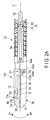
- a medical treatment system 10 includes a treatment device (medical treatment instrument) 12, an energy source 14, and a foot switch 16 having a pedal 16a.
- the treatment device 12 includes a handle 22, a shaft 24 having a central axis C, and a treatment portion 26.
- the energy source 14 is connected to the handle 22 via a cable 28.
- the foot switch 16 is connected to the energy source 14. A surgeon (user) operates the pedal 16a of the foot switch 16 by foot, and thereby switches on and off the supply of energy from the energy source 14 to the treatment portion 26 of the treatment instrument 12.
- the handle 22 is substantially L-shaped.
- the shaft 24 is provided at one end (distal end) of the handle 22.
- the above-mentioned cable 28 extends from the proximal end of the handle 22 which is substantially coaxial with the shaft 24.
- the other end 22b of the handle 22 is a grasp portion to be grasped by the surgeon.
- the handle 22 includes a treatment portion open-close knob (first operation body) 32 provided in parallel with the other end 22b.
- the treatment portion open-close knob 32 is disposed in front of the other end 22b of the handle 22.
- the treatment portion open-close knob 32 is rotatable inside the handle 22 by an unshown pivot shaft, that is, can be brought closer to or away from the other end of the handle 22.
- the treatment portion open-close knob 32 is coupled to the proximal end of a later-described external cylinder 44 of the shaft 24 substantially in the central part of the handle 22.
- the later-described external cylinder 44 of the shaft 24 is advanced relative to the handle 22 along its axial direction.
- the later-described external cylinder 44 is retreated relative to the handle 22 along its axial direction.
- the handle 22 further includes a cutter driving knob (second operation body) 34 provided in parallel with the treatment portion open-close knob 32 to move a later-described cutter 54.
- the cutter driving knob 34 is rotatable inside the handle 22 by an unshown pivot shaft, that is, can be brought closer to or away from the other end 22b of the handle 22.
- This cutter driving knob 34 is located in front of the treatment portion open-close knob 32, and coupled to the proximal end of a later-described drive rod 52.
- the drive rod 52 is advanced along its axial direction, and then the later-described cutter 54 is advanced.
- the cutter driving knob 34 is brought away from the other end 22b of the handle 22, the drive rod 52 is retreated along its axial direction, and then the cutter 54 is retreated.
- the shaft 24 includes an internal cylinder 42, and the external cylinder 44 slidably provided outside the internal cylinder 42. It is preferable that the central axes C of the internal cylinder 42 and the external cylinder 44 correspond to each other. It is preferable that the internal cylinder 42 and the external cylinder 44 have their inner circumferential surfaces and outer circumferential surfaces covered with a material having electrical insulating properties.
- the internal cylinder 42 is fixed in its proximal end portion to the handle 22.
- the external cylinder 44 is slidable along the axial direction of the internal cylinder 42.
- the drive rod 52 is provided movably along its axial direction. It is preferable that the central axis C of the drive rod 52 corresponds to the central axis C of the shaft 24, that is, the internal cylinder 42 and the external cylinder 44.
- the thin plate-shaped cutter (treatment assistive device) 54 is provided at the distal end of the drive rod 52.
- the cutter 54 has an edge 54a formed at its distal end.
- the cutter 54 moves along later-described first and second cutter guide grooves (flow paths, fluid release grooves) 152 and 154 (see FIG. 4A to FIG. 5C ). Particularly when the distal end of the cutter 54 has most advanced, the distal end of the cutter 54 is located slightly closer to the proximal end side than the distal ends of the cutter guide grooves 152 and 154.
- the distal end of the cutter 54 is set to be located inside the distal end of the internal cylinder 42 or located at the positions of the proximal ends of the cutter guide grooves 152 and 154 without contacting the living tissue when the distal end of the cutter 54 has most retreated.
- the treatment portion 26 is provided at the distal end of the shaft 24.
- the treatment portion 26 includes the first and second grasping members 72 and 74, a swing member 76, first and second holding surfaces 80 and 82, first and second energy applying portions (high-frequency electrodes) 84 and 86, and a protrusion 88.
- Each of the first and second grasping members 72 and 74 has electric insulating properties in at least its outer circumferential surface.
- first grasping member 72 is openable and closable relative to the second grasping member 74 in the case described in this embodiment, a structure in which both the first and second grasping members 72 and 74 are openable and closable relative to each other may be used.
- Outer surfaces of the first and second grasping members 72 and 74 opposite to the first and second holding surfaces 80 and 82 are formed into smooth curved surfaces.
- the distal end of the internal cylinder 42 has a swing supporting point S1 which rotatably supports the proximal end portion of the first grasping member 72.
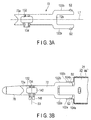
- the distal end of the external cylinder 44 located on the outer circumference of the external cylinder 44 has a pair of planes 102a and 102b (see FIG. 3B ) which respectively have long holes 104a and 104b (see FIG. 2A and FIG. 2B ) formed therein and which are parallel to each other.
- the long holes 104a and 104b are formed to be longer, for example, in a direction that deviates from the direction parallel to the central axis C.
- a later-described pair of arms 122a and 122b of the first grasping member 72 are movably supported by the long holes 104a and 104b between the pair of planes 102a and 102b.
- the second grasping member 74 is, for example, integrally provided at the distal end of the external cylinder 44.
- the first grasping member 72 includes a distal end portion 72a, a proximal end portion 72b, and a longitudinal axis L1 defined by the distal end portion 72a and the proximal end portion 72b.
- the proximal end portion 72b of the first grasping member 72 shown in FIG. 2A and FIG. 2B has a pair of arms 122a and 122b in a direction that deviates from the longitudinal axis L1.
- the pair of arms 122a and 122b of the first grasping member 72 are supported on the swing supporting point S1 rotatably relative to the distal end of the internal cylinder 42.
- the pair of arms 122a and 122b have action supporting points S2 movable in the long holes 104a and 104b at the distal end of the external cylinder 44. These action supporting points S2 respectively protrude outward from the pair of arms 122a and 122b.
- the action supporting points S2 of the pair of arms 122a and 122b are disposed between the planes 102a and 102b at the distal end of the external cylinder 44, and are movable in the long holes 104a and 104b of the planes 102a and 102b.
- the first grasping member 72 is located at the closed position shown in FIG. 2A .
- the first grasping member 72 is located at the opened position shown in FIG. 2B .
- the first grasping member 72 is openable and closable relative to the second grasping member 74.
- the distal end portion 72a of the first grasping member 72 has a support recess 132 which rotatably supports the swaying member 76, and a screw hole 134 which extends through the support recess 132.
- the screw hole 134 extends in a direction which intersects at right angles with the longitudinal axis L1 and which intersects at right angles with the open-close direction of the first and second grasping members 72 and 74.
- the swing member 76 made of a material having electric insulating properties and heat resisting properties is pivotally supported by the first grasping member 72 on a support shaft S3.
- the swing member 76 includes a distal end 76a, a proximal end 76b, and a longitudinal axis L11 defined by the distal end 76a and the proximal end 76b.
- the distal end 76a of the swing member 76 is located close to the distal end portion 72a of the first grasping member 72.
- the proximal end 76b of the swing member 76 is located close to the proximal end portion 72b of the first grasping member 72.
- the swing member 76 has a support projection 142 which rotates on the support shaft S3 extending in a direction perpendicular to the longitudinal axis L1 of the first grasping member 72 and the longitudinal axis L11 of the swing member 76 in a direction that intersects at right angles with the open-close direction of the first and second grasping members 72 and 74.
- the support projection 142 has a through-hole 144 around the support shaft S3.
- the support projection 142 of the swing member 76 is fitted to the support recess 132 of the first grasping member 72, and the screw hole 134 of the support recess 132 is aligned with the through-hole 144 of the support projection 142, and then a screw 146 is tightened.
- the swing member 76 is rotatable on the support shaft S3 in a first direction (clockwise direction) D1 and a second direction (counterclockwise direction) D2 in FIG. 4B .
- FIG. 4B means, for example, a condition in which the distal end side of the swing member 76 has risen relative to the proximal end side while the first grasping member 72 is closed relative to the second grasping member 74.
- the case in which the swing member 76 rotates in the second direction (counterclockwise direction) D2 in FIG. 4B means, for example, a condition in which the distal end side of the swing member 76 has lowered relative to the proximal end side while the first grasping member 72 is closed relative to the second grasping member 74.
- the support shaft S3 of the swing member 76, the swing supporting point S1 at the distal end of the internal cylinder 42, and the action supporting point S2 at the distal end of the external cylinder 44 are parallel to one another.
- the support shaft S3 is located at a middle position between the distal end 76a and the proximal end 76b of the swing member 76 along the longitudinal axis L11, or located on the side closer to the distal end 76a than the middle position. That is, the support shaft S3 is supported in an area close to the distal end 76a including the middle position between the distal end 76a and the proximal end 76b of the swing member 76. As schematically shown in FIG. 6A , it is described here that the support shaft S3 is located at the middle position between the distal end 76a and the proximal end 76b of the swing member 76 along the longitudinal axis L11.
- the first holding surface 80 which cooperates with the later-described second holding surface 82 to grasp the living tissue is provided on the side of the swing member 76 closer to the second grasping member 74.
- the first holding surface 80 is formed as an outer edge of the swing member 76 in this embodiment, the first holding surface 80 is suitably changed depending on the shape and size of the first high-frequency electrode 84.
- the thin plate-shaped first high-frequency electrode (first energy applying portion) 84 which applies high-frequency energy to the living tissue held between the first and second holding surfaces 80 and 82 to generate heat in the living tissue is fixed to the first holding surface 80.
- the surface of the first high-frequency electrode 84 is substantially U-shaped, and cooperates with the first holding surface 80 to form a first cutter guide groove (treatment assistive device guide groove) 152 to guide the cutter 54. That is, the first holding surface 80 and the first high-frequency electrode 84 have the linear first cutter guide groove (treatment assistive tool guide groove) 152 at a position along the central axis C. It is preferable that the width of the first cutter guide groove 152 is formed to be as small as possible.
- the distal end of the first high-frequency electrode 84 is closed in the vicinity of the distal end of the swing member 76, and the proximal end of the first high-frequency electrode 84 is divided into two parts in the vicinity of the proximal end of the swing member 76.
- the inside edge of the first high-frequency electrode 84 is formed as the cutter guide groove 152. It is preferable that the rear surface and outer edge of the first high-frequency electrode 84 are covered with the swing member 76.
- the second grasping member 74 has a distal end portion 74a, a proximal end portion 74b, and a longitudinal axis L12 defined by the distal end portion 74a and the proximal end portion 74b. It is preferable that the second grasping member 74 is formed integrally with the distal end of the external cylinder 44.
- the second holding surface 82 which cooperates with the first holding surface 80 to grasp the living tissue is provided.
- the second holding surface 82 is formed as an outer edge of the second grasping member 74 in this embodiment, the second holding surface 82 is suitably changed depending on the shape and size of the second high-frequency electrode 86.
- the thin plate-shaped second high-frequency electrode (second energy applying portion) 86 which applies high-frequency energy to the living tissue held between the first and second holding surfaces 80 and 82 to generate heat in the living tissue is fixed to the second holding surface 82.
- This second high-frequency electrode 86 is substantially U-shaped in the same manner as the first high-frequency electrode 84, and cooperates with the second holding surface 82 to form a second cutter guide groove (treatment assistive device guide groove) 154 to guide the cutter 54. That is, the second holding surface 82 and the second high-frequency electrode 86 have the linear second cutter guide groove (treatment assistive tool guide groove) 154 at a position along the central axis C. It is preferable that the width of the second cutter guide groove 154 is formed to be as small as possible.
- the second high-frequency electrode 86 is substantially U-shaped, the distal end of the second high-frequency electrode 86 is closed in the vicinity of the distal end of the second grasping member 74, and the proximal end of the second high-frequency electrode 86 is divided into two parts in the vicinity of the proximal end of the second grasping member 74.
- the inside edge of the second high-frequency electrode 86 is formed as the cutter guide groove 154. It is preferable that the rear surface and outer edge of the second high-frequency electrode 86 are covered with the second grasping member 74.
- the first high-frequency electrode 84 is electrically connected to the energy source 14 by an unshown conducting wire through the internal cylinder 42 or between the internal cylinder 42 and the external cylinder 44 and through the cable 28.
- the second high-frequency electrode 86 is electrically connected to the energy source 14 by an unshown conducting wire through the internal cylinder 42 or between the internal cylinder 42 and the external cylinder 44 and through the cable 28.
- first and second high-frequency electrodes 84 and 86 are formed to be longer in a direction parallel to the longitudinal axis L than in a direction perpendicular to the longitudinal axis L.
- the living tissue disposed between the first and second high-frequency electrodes 84 and 86 can be continuously and seamlessly sealed.
- the sealed living tissue can be separated into two parts by guiding the cutter 54 through the first and second cutter guide grooves 152 and 154.
- the protrusion (spacer) 88 is provided on the surface of the second high-frequency electrode 86 to maintain a distance between the first high-frequency electrode 84 and the second high-frequency electrode 86 and prevent contact while the first and second grasping members 72 and 74 are closed.
- the protrusion 88 is made of a material having heat resisting properties and electric insulating properties.
- a resin material such as PTFE and PEEK, ceramics, or a material such as PTFE having heat resisting properties and electric insulating properties which covers the periphery of a metallic material is used for the protrusion 88.
- the height and hardness are adjusted in consideration of the deformation of the resin material pressed by the first high-frequency electrode 84 and the living tissue.
- the protrusion 88 is located close to the distal end of the second cutter guide groove 154. It is also preferable that the protrusion 88 is located at a position that does not prevent the second high-frequency electrode 86 from seamlessly and continuously sealing the living tissue. According to this embodiment, the protrusion 88 is located in the vicinity of the distal end portion of the surface of each of the first and second high-frequency electrodes 84 and 86 and located closer to its inner edge (second cutter guide groove 154) than its outer edge.
- One protrusion 88 is not exclusively provided. More than one protrusion 88, for example, two protrusions 88 may be provided as long as the protrusions do not prevent the second high-frequency electrode 86 from seamlessly and continuously sealing the living tissue.
- the protrusion 88 is mounted on the second high-frequency electrode 86 in a fixed state. However, it is also preferable that the protrusion 88 is fixed to the second grasping member 74 through the second high-frequency electrode 86 because the protrusion 88 has heat resisting properties and electric insulating properties.
- the first and second cutter guide grooves 152 and 154 are also used as fluid release grooves which are in communication with the inside of the internal cylinder 42 where the drive rod 52 of the cutter 54 is provided and which receive a fluid generated from the living tissue.
- a restriction portion 90 is formed in the distal end portion 72a of the first grasping member 72.
- the restriction portion 90 can inhibit, that is, limit the clockwise rotation of the swing member 76 in FIG. 6A .
- the restriction portion 90 is not exclusively formed in the distal end portion 72a of the first grasping member 72, and it is also preferable that the restriction portion 90 is formed in the swing member 76.
- the treatment portion 26 according to this embodiment has the structure described below.
- the first grasping member 72 includes the distal end portion 72a, the proximal end portion 72b, and the longitudinal axis L1 defined by the distal end portion 72a and the proximal end portion 72b.
- the swing member 76 is supported between the distal end portion 72a and the proximal end portion 72b of the first grasping member 72.
- the swing member 76 is rotatable in the first direction D1 and in the second direction D2 opposite to the first direction D1 on the support shaft S3 extending in a direction perpendicular to the longitudinal axis L11 and in a direction that intersects at right angles with the open-close direction of the first and second grasping members 72 and 74.
- the first grasping member 72 and the swing member 76 form what is known as a seesaw jaw.
- the support shaft S3 of the swing member 76 is supported at the middle position between the distal end 76a and the proximal end 76b of the swing member 76.
- the first holding surface 80 is provided on the side of the swing member 76 closer to the second grasping member 74, and can grasp the living tissue.
- the second holding surface 82 is provided on the side of the second grasping member 74 closer to the swing member 76, faces the first holding surface 80, and can cooperate with the first holding surface 80 of the swing member 76 to grasp the living tissue.
- the treatment portion 26 of the treatment device 12 has the first and second high-frequency electrodes 84 and 86 which are provided in the first and second holding surfaces 80 and 82 and which apply energy to the living tissue held between the first and second holding surfaces 80 and 82, and also has the protrusion 88 which is provided in the second holding surface 82 and which forms a clearance between the first and second holding surfaces 80 and 82 when the first and second holding surfaces 80 and 82 are closed relative to each other.
- the treatment portion 26 of the treatment device 12 also includes the cutter (treatment assistive tool) 54 which is movable between the position located between the swing member 76 and the second grasping member 74 and the position to escape from the position located between the swing member 76 and the second grasping member 74, the first cutter guide groove 152 which is provided in the first holding surface 80 and which guides the cutter 54 between the first and second holding surfaces 80 and 82, and the second cutter guide groove 154 which is provided in the second holding surface 82 and which cooperates with the first cutter guide groove 152 to guide the cutter 54.
- the cutter treatment assistive tool
- the treatment portion 26 is inserted into a lumen such as a body cavity while the first grasping member 72 is closed relative to the second grasping member 74.
- the treatment portion 26 is then placed to face a living tissue to be treated.
- the treatment portion open-close knob 32 of the handle 22 is pulled to advance the external cylinder 44 relative to the internal cylinder 42.
- the first grasping member 72 is opened relative to the second grasping member 74.
- the living tissue to be treated is disposed between the first and second holding surfaces 80 and 82. That is, the living tissue to be treated is disposed between the first and second high-frequency electrodes 84 and 86.
- the treatment portion open-close knob 32 located before the handle 22 is moved forward, and the external cylinder 44 is retreated relative to the internal cylinder 42.
- the first grasping member 72 is closed relative to the second grasping member 74. That is, the living tissue to be treated is held between the first and second high-frequency electrodes 84 and 86.
- the treatment portion 26 of the treatment device 12 grasps the living tissue to be treated, for example, at the position closer to the proximal end 76b than the middle part between the distal end 76a and the proximal end 76b of the first holding surface 80 of the swing member 76 and in the second holding surface 82 facing the first holding surface 80.
- a grasp force is applied to the living tissue from the condition in which the protrusion 88 provided in the surface of the second holding surface 82 or the second high-frequency electrode 86 has separated from the first holding surface 80 or the first high-frequency electrode 84 and the condition in which the first and second holding surfaces 80 and 82 are parallel to each other, the first holding surface 80 moves in a manner shown from FIG. 6A to FIG. 6C .
- FIG. 6A shows the moment when a living tissue L T is brought into contact with both the first and second holding surfaces 80 and 82.
- the first grasping member 72 is urged to be closed relative to the second grasping member 74.
- the living tissue L T is pressed while the distal end side of the support shaft S3 of the swing member 76 falls and the proximal end side rises, so that the escape of the living tissue L T to the distal end side is prevented, and force is applied to the living tissue L T toward the lower side of the second holding surface 82 (closing direction of the first grasping member 72) or toward the proximal end side of the second grasping member 74. Therefore, force is applied to move the living tissue L T toward the proximal end sides of the swing member 76 and the second grasping member 74 at the moment when the living tissue L T is held between the first and second holding surfaces 80 and 82.
- the swing member 76 rotates around the support shaft S3 due to a reaction force from the living tissue L T as a press force (holding force) applied to the living tissue L T between the first and second holding surfaces 80 and 82 increases. At this point, the swing member 76 rotates in a clockwise direction D1. Thus, when the first and second holding surfaces 80 and 82 are completely closed, the living tissue L T is grasped with a uniform holding force.
- the distal end 76a of the swing member 76 closes relative to the second holding surface 82 earlier than the proximal end 76b.
- the first holding surface 80 or the first high-frequency electrode 84 grasps the living tissue with a uniform grasp force immediately after applying a force to the living tissue in a direction perpendicular to the surface of the second holding surface 82 or the second high-frequency electrode 86 (particularly in the closing direction of the first grasping member 72) or toward the proximal end side of the second grasping member 74.
- a space G is maintained between the first and second high-frequency electrodes 84 and 86 by the protrusion 88 and the restriction portion 90 to prevent the first and second high-frequency electrodes 84 and 86 from contacting each other and causing a short circuit.
- the pedal 16a of the foot switch 16 is depressed by the foot. Accordingly, high-frequency energy is applied to the living tissue between the first and second high-frequency electrodes 84 and 86 from the energy source 14 to heat the living tissue and then coagulate the living tissue. At this point, the living tissue is coagulated regardless of the widths of the first and second cutter guide grooves 152 and 154 because the widths of the cutter guide grooves 152 and 154 are formed to be narrow. The cutter 54 is then moved along the cutter guide grooves 152 and 154 as needed to cut the treated living tissue.
- the rotary member 76 is pivotally supported by the first grasping member 72 on the support shaft S3, and the first grasping member 72 and the rotary member 76 form what is known as a seesaw jaw.
- the amount of holding force to hold the living tissue between the first holding surface 80 and the first high-frequency electrode 84 of the swing member 76 and the second holding surface 82 and the second high-frequency electrode 86 of the second grasping member 74 can be uniform.
- the distal end 76a of the swing member 76 can be brought closer to the second holding surface 82 earlier than the proximal end 76b.
- the treatment device 12 when performing the operation of grasping the living tissue, can maximally prevent the living tissue from escaping to the side of the distal end 76a of the swing member 76 and the distal end side of the second grasping member 74, that is, the distal end side of the first and second holding surfaces 80 and 82.
- the protrusion 88 and the limiting portion 90 can prevent the first and second high-frequency electrodes 84 and 86 from contacting each other.
- the protrusion 88 also has an anti-slip function, so that it is possible to inhibit the living tissue from slipping toward the distal end side and proximal end side of the first and second holding surfaces 80 and 82.
- the support shaft S3 is disposed substantially in the middle part between the distal end 76a and the proximal end 76b of the swing member 76, that is, substantially in the middle part between the distal end 76a and the proximal end 76b of the first holding surface 80.
- the support shaft S3 is disposed between the middle part between the distal end 76a and the proximal end 76b of the swing member 76, and the distal end 76a of the swing member 76.
- the living tissue is grasped from the position closer to the distal end 76a including the middle part between the distal end 76a and the proximal end 76b of the first holding surface 80 to the position close to the proximal end 76b. Since the support shaft S3 is located closer to the distal end side than the middle part between the distal end 76a and the proximal end 76b of the first holding surface 80, the first holding surface 80 contacts the living tissue, and the swing member 76 rotates around the support shaft S3 (counterclockwise around the support shaft S3 in FIG. 7A ), so that the distal end 76a of the first holding surface 80 comes closer to the second holding surface 82 than the proximal end 76b. Thus, the escape of the living tissue to the distal end side relative to the first holding surface 80 is prevented. When the first holding surface 80 is brought close to the second holding surface 82, the living tissue can be grasped with a uniform grasp force.
- FIG. 7B An example of an undesirable treatment portion 26a is shown in FIG. 7B .
- the support shaft S3 is disposed between the middle part between the distal end 76a and the proximal end 76b of the swing member 76, and the proximal end 76b of the swing member 76.
- the swing member 76 rotates around the support shaft S3 (clockwise around the support shaft S3 in FIG.
- the distal end 76a of the first holding surface 80 comes farther away from the second holding surface 82 than the proximal end 76b.
- the distal end 76a of the first holding surface 80 easily rises relative to the proximal end 76b, and the living tissue is more easily pushed out to the distal end side of the first holding surface 80.
- This embodiment is a modification of the first embodiment.
- the same components as the components described in the first embodiment or the components having the same functions are provided with the same signs wherever possible, and detailed explanations thereof are omitted.
- the support shaft S3 is located in between the distal end 76a and the proximal end 76b of the swing member 76 in the example illustrated in FIG. 8A to FIG. 8D , the support shaft S3 may be located at a position closer to the distal end 76a than midway between the distal end 76a and the proximal end 76b of the swing member 76 as shown in FIG. 7A . That is, the support shaft S3 is located on the distal end side including the middle of the swing member 76.
- the treatment portion 26 shown in FIG. 8A has a compression spring (elastic member) 212 disposed between the distal end portion 72a of the first grasping member 72 and the distal end 76a of the swing member 76.
- the compression spring 212 urges the distal end 76a of the swing member 76 to come closer to the second grasping member 74 than the proximal end 76b of the swing member 76 by the distal end portion 72a of the first grasping member 72.
- the compression spring 212 is disposed between the side closer to the distal end portion 72a of the first grasping member 72 than the support shaft S3 and the side close to the distal end 76a of the swing member 76, and brings the side close to the distal end portion 72a of the first grasping member 72 away from the side close to the distal end 76a of the swing member 76.
- the compression spring 212 also functions as a coupling member to couple the distal end portion 72a of the first grasping member 72 to the distal end 76a of the swing member 76.
- a columnar resin material (elastic member) having a similar elastic function may be used.
- the treatment portion 26 shown in FIG. 8B has a tension spring 214 disposed between the proximal end portion 72b of the first grasping member 72 and the proximal end 76b of the swing member 76.
- the tension spring 214 urges the proximal end 76b of the swing member 76 to move farther away from the second grasping member 74 than the distal end 76a of the swing member 76 by the proximal end portion 72b of the first grasping member 72.
- the tension spring 214 is disposed between the side closer to the proximal end portion 72b of the first grasping member 72 than the support shaft S3 and the side close to the proximal end 76b of the swing member 76, and brings the side close to the proximal end portion 72b of the first grasping member 72 away from the side close to the proximal end 76b of the swing member 76.
- the tension spring 214 also functions as a coupling member to couple the proximal end portion 72b of the first grasping member 72 to the proximal end 76b of the swing member 76.
- a columnar resin material (elastic member) having a similar elastic function may be used.
- the treatment portion 26 shown in FIG. 8C has a torsion spring (elastic member) 216 disposed on the support shaft S3 of the first grasping member 72 and the swing member 76.
- the torsion spring 216 urges the distal end 76a of the swing member 76 to come closer to the second grasping member 74 than the proximal end 76b of the swing member 76, and urges the proximal end 76b of the swing member 76 to move farther away from the second grasping member 74 than the distal end 76a of the swing member 76.
- the torsion spring 216 also functions as a coupling member to couple the first grasping member 72 to the swing member 76.
- the treatment portion 26 shown in FIG. 8D has a leaf spring (elastic member) 218 disposed on the swing member 76 and the swing supporting point S1.
- the leaf spring 218 according to this embodiment has, for example, a first surface 222a coupled to the swing member 76, a second surface 222b coupled to the swing supporting point S1, and a third surface 222c disposed between the first and second surfaces 222a and 222b.
- the first surface 222a urges the proximal end 76b of the swing member 76 to move farther away from the second grasping member 74 than the distal end 76a.
- the leaf spring 218 also functions as a coupling member to couple the first grasping member 72 to the swing member 76.
- first and second surfaces 222a and 222b are formed, for example, substantially parallel in a no-load state as shown in FIG. 8D .
- the third surface 222c is formed as an inclined surface which is inclined relative to the first and second surfaces 222a and 222b.
- FIG. 8A to FIG. 8D The functions of the examples shown in FIG. 8A to FIG. 8D are described in connection with the representative example in which the leaf spring 218 shown in FIG. 8D is disposed.
- the first grasping member 72 is closed relative to the second grasping member 74.
- the proximal end 76b of the swing member 76 is raised closer to the proximal end portion 72b of the first grasping member 72, and the distal end 76a of the swing member 76 comes close to the second grasping member 74 earlier than the proximal end 76b.
- FIG. 9C when the swing member 76 is completely closed relative to the second grasping member 74, the first holding surface 80 of the swing member 76 and the second holding surface 82 of the second grasping member 74 become parallel due to the operation of the leaf spring 218.
- the protrusion 88 does not need to be provided in the second holding surface 82, and it is also preferable that the protrusion 88 is provided in the first holding surface 80 as shown in FIG. 9A to FIG. 9C . That is, the protrusion 88 has only to be provided in at least one of the first and second holding surfaces 80 and 82.
- the living tissue L T is located at the position closer to the proximal end 76b than the middle part between the distal end 76a and the proximal end 76b of the swing member 76.
- the elastic member is used for the treatment portion 26 described in the first embodiment as in the examples shown in the second embodiment ( FIG. 8A to FIG.
- the distal end 76a of the swing member 76 can be brought close to the second holding surface 82 earlier than the proximal end 76b when the first holding surface 80 is closed relative to the second holding surface 82 even if the living tissue L T is located at the position close to the middle part between the distal end 76a and the proximal end 76b of the swing member 76 or close to the proximal end 76b. That is, when the first holding surface 80 shown in FIG. 8A to FIG.
- the living tissue L T may be located in the middle part between the distal end 76a and the proximal end 76b of the swing member 76, at the position close to the distal end 76a, or at the position close to the proximal end 76b.
- the distal end 76a of the swing member 76 can be brought close to the second holding surface 82 earlier than the proximal end 76b even if the living tissue is located at any position between the distal end 76a and the proximal end 76b of the swing member 76.
- This embodiment is a modification of the first and second embodiments.
- the same components as the components described in the first and second embodiments or the components having the same functions are provided with the same signs wherever possible, and detailed explanations thereof are omitted.
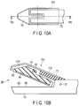
- a covering member 232 may be disposed on the outer circumference of the first grasping member 72 of the treatment portion 26.
- the covering member 232 covers the part of the first grasping member 72 opposite to the swing member 76. That is, the covering member 232 covers the part of the distal end 76a of the swing member 76 opposite to the first holding surface 80.
- This covering member 232 has a cavity area 234 between the covering member 232 and the distal end 76a of the swing member 76.
- the cavity area 234 of the covering member 232 functions as a heat insulating portion, so that when, for example, high-frequency energy is applied to the living tissue, it is possible to prevent the heat from the first holding surface 80 from escaping to the outside through the swing member 76 and the first grasping member 72.
- the covering member 232 covers the part of the first grasping member 72 opposite to the swing member 76, so that a temperature increase in the outer surface of the first grasping member 72 (the side of the first grasping member 72 opposite to the swing member 76) can be inhibited by the heat insulating properties of the covering member 232 even if the heat from the first holding surface 80 is transmitted to the outside through the swing member 76 and the first grasping member 72.
- the first high-frequency electrode 84 is present in the first holding surface 80, and the second high-frequency electrode 86 is disposed in the second holding surface 82.
- no first and second high-frequency electrodes (energy applying portions) 84 and 86 may be disposed.
- the cutter 54 and the cutter guide grooves 152 and 154 are not always necessary.
- the high-frequency electrodes 84 and 86 are not exclusively substantially U-shaped, and can be any suitable shape.
- first and second high-frequency electrodes 84 and 86 in the treatment instrument 12 described according to the first to third embodiments are bipolar types, the first and second high-frequency electrodes 84 and 86 may be monopolar types which are used so that an unshown return electrode is attached to a patient.
- thin plate-shaped heaters energy applying portions
- thin plate-shaped heaters disposed on the rear surfaces of the thin plate-shaped high-frequency electrodes 84 and 86 may be used.
- the treatment assistive device is not limited to the cutter as long as the treatment assistive device is used to assistive in a treatment.
- an ultrasonically vibrating probe may be used instead of the cutter 54.
Applications Claiming Priority (2)
| Application Number | Priority Date | Filing Date | Title |
|---|---|---|---|
| US201361802875P | 2013-03-18 | 2013-03-18 | |
| PCT/JP2014/056001 WO2014148281A1 (fr) | 2013-03-18 | 2014-03-07 | Outil de traitement |
Publications (2)
| Publication Number | Publication Date |
|---|---|
| EP2977018A1 true EP2977018A1 (fr) | 2016-01-27 |
| EP2977018A4 EP2977018A4 (fr) | 2016-11-30 |
Family
ID=51579968
Family Applications (1)
| Application Number | Title | Priority Date | Filing Date |
|---|---|---|---|
| EP14769158.8A Withdrawn EP2977018A4 (fr) | 2013-03-18 | 2014-03-07 | Outil de traitement |
Country Status (5)
| Country | Link |
|---|---|
| US (1) | US9993289B2 (fr) |
| EP (1) | EP2977018A4 (fr) |
| JP (1) | JP5663710B1 (fr) |
| CN (1) | CN104703555B (fr) |
| WO (1) | WO2014148281A1 (fr) |
Cited By (2)
| Publication number | Priority date | Publication date | Assignee | Title |
|---|---|---|---|---|
| EP3845182A1 (fr) * | 2019-12-30 | 2021-07-07 | Ethicon LLC | Électrode déflectable biaisée pour minimiser le contact entre une lame ultrasonique et une électrode |
| EP3854336A3 (fr) * | 2019-12-30 | 2021-11-10 | Ethicon LLC | Support déflectable d'électrode d'énergie rf par rapport à la lame ultrasonore opposée |
Families Citing this family (35)
| Publication number | Priority date | Publication date | Assignee | Title |
|---|---|---|---|---|
| US11090104B2 (en) | 2009-10-09 | 2021-08-17 | Cilag Gmbh International | Surgical generator for ultrasonic and electrosurgical devices |
| GB2480498A (en) | 2010-05-21 | 2011-11-23 | Ethicon Endo Surgery Inc | Medical device comprising RF circuitry |
| US9333025B2 (en) | 2011-10-24 | 2016-05-10 | Ethicon Endo-Surgery, Llc | Battery initialization clip |
| US9408622B2 (en) | 2012-06-29 | 2016-08-09 | Ethicon Endo-Surgery, Llc | Surgical instruments with articulating shafts |
| US10159524B2 (en) | 2014-12-22 | 2018-12-25 | Ethicon Llc | High power battery powered RF amplifier topology |
| WO2016171067A1 (fr) * | 2015-04-24 | 2016-10-27 | オリンパス株式会社 | Dispositif médical |
| CN107920853A (zh) * | 2015-08-05 | 2018-04-17 | 奥林巴斯株式会社 | 处置器具 |
| CN107920838B (zh) * | 2015-09-17 | 2020-08-21 | 奥林巴斯株式会社 | 抓持处置器具 |
| US11058475B2 (en) | 2015-09-30 | 2021-07-13 | Cilag Gmbh International | Method and apparatus for selecting operations of a surgical instrument based on user intention |
| US10959771B2 (en) | 2015-10-16 | 2021-03-30 | Ethicon Llc | Suction and irrigation sealing grasper |
| US10959806B2 (en) | 2015-12-30 | 2021-03-30 | Ethicon Llc | Energized medical device with reusable handle |
| US11229471B2 (en) | 2016-01-15 | 2022-01-25 | Cilag Gmbh International | Modular battery powered handheld surgical instrument with selective application of energy based on tissue characterization |
| US10987156B2 (en) | 2016-04-29 | 2021-04-27 | Ethicon Llc | Electrosurgical instrument with electrically conductive gap setting member and electrically insulative tissue engaging members |
| US10856934B2 (en) | 2016-04-29 | 2020-12-08 | Ethicon Llc | Electrosurgical instrument with electrically conductive gap setting and tissue engaging members |
| US20170312018A1 (en) * | 2016-04-29 | 2017-11-02 | Ethicon Endo-Surgery, Llc | Electrosurgical instrument with conductive gap setting member and insulative tissue engaging member having variable dimensions and stiffness |
| CN109195535B (zh) * | 2016-05-25 | 2021-05-04 | 奥林巴斯株式会社 | 把持处置器具以及把持处置器具的制造方法 |
| US10751117B2 (en) | 2016-09-23 | 2020-08-25 | Ethicon Llc | Electrosurgical instrument with fluid diverter |
| US11033325B2 (en) | 2017-02-16 | 2021-06-15 | Cilag Gmbh International | Electrosurgical instrument with telescoping suction port and debris cleaner |
| US10799284B2 (en) | 2017-03-15 | 2020-10-13 | Ethicon Llc | Electrosurgical instrument with textured jaws |
| US11497546B2 (en) | 2017-03-31 | 2022-11-15 | Cilag Gmbh International | Area ratios of patterned coatings on RF electrodes to reduce sticking |
| US10603117B2 (en) | 2017-06-28 | 2020-03-31 | Ethicon Llc | Articulation state detection mechanisms |
| US11033323B2 (en) | 2017-09-29 | 2021-06-15 | Cilag Gmbh International | Systems and methods for managing fluid and suction in electrosurgical systems |
| US11484358B2 (en) | 2017-09-29 | 2022-11-01 | Cilag Gmbh International | Flexible electrosurgical instrument |
| US11490951B2 (en) | 2017-09-29 | 2022-11-08 | Cilag Gmbh International | Saline contact with electrodes |
| USD904611S1 (en) | 2018-10-10 | 2020-12-08 | Bolder Surgical, Llc | Jaw design for a surgical instrument |
| DE112018007991T5 (de) * | 2018-10-22 | 2021-05-27 | Olympus Corporation | Behandlungswerkzeug |
| US11950797B2 (en) | 2019-12-30 | 2024-04-09 | Cilag Gmbh International | Deflectable electrode with higher distal bias relative to proximal bias |
| US11779387B2 (en) | 2019-12-30 | 2023-10-10 | Cilag Gmbh International | Clamp arm jaw to minimize tissue sticking and improve tissue control |
| US11911063B2 (en) * | 2019-12-30 | 2024-02-27 | Cilag Gmbh International | Techniques for detecting ultrasonic blade to electrode contact and reducing power to ultrasonic blade |
| US11937863B2 (en) | 2019-12-30 | 2024-03-26 | Cilag Gmbh International | Deflectable electrode with variable compression bias along the length of the deflectable electrode |
| US11786294B2 (en) | 2019-12-30 | 2023-10-17 | Cilag Gmbh International | Control program for modular combination energy device |
| US11812957B2 (en) | 2019-12-30 | 2023-11-14 | Cilag Gmbh International | Surgical instrument comprising a signal interference resolution system |
| US11944366B2 (en) * | 2019-12-30 | 2024-04-02 | Cilag Gmbh International | Asymmetric segmented ultrasonic support pad for cooperative engagement with a movable RF electrode |
| WO2021152753A1 (fr) * | 2020-01-29 | 2021-08-05 | オリンパス株式会社 | Instrument de traitement et procédé de fabrication d'un instrument de traitement |
| USD934423S1 (en) | 2020-09-11 | 2021-10-26 | Bolder Surgical, Llc | End effector for a surgical device |
Family Cites Families (15)
| Publication number | Priority date | Publication date | Assignee | Title |
|---|---|---|---|---|
| US20030171747A1 (en) * | 1999-01-25 | 2003-09-11 | Olympus Optical Co., Ltd. | Medical treatment instrument |
| US7083618B2 (en) * | 2001-04-06 | 2006-08-01 | Sherwood Services Ag | Vessel sealer and divider |
| WO2005120376A2 (fr) * | 2004-06-02 | 2005-12-22 | Medtronic, Inc. | Dispositif d'ablation comprenant des machoires |
| US7540872B2 (en) | 2004-09-21 | 2009-06-02 | Covidien Ag | Articulating bipolar electrosurgical instrument |
| US7918848B2 (en) | 2005-03-25 | 2011-04-05 | Maquet Cardiovascular, Llc | Tissue welding and cutting apparatus and method |
| US7717914B2 (en) * | 2006-07-11 | 2010-05-18 | Olympus Medical Systems Corporation | Treatment device |
| US20080015575A1 (en) | 2006-07-14 | 2008-01-17 | Sherwood Services Ag | Vessel sealing instrument with pre-heated electrodes |
| US20090048595A1 (en) | 2007-08-14 | 2009-02-19 | Takashi Mihori | Electric processing system |
| US8795274B2 (en) * | 2008-08-28 | 2014-08-05 | Covidien Lp | Tissue fusion jaw angle improvement |
| US8784417B2 (en) * | 2008-08-28 | 2014-07-22 | Covidien Lp | Tissue fusion jaw angle improvement |
| US8974477B2 (en) * | 2008-08-29 | 2015-03-10 | Olympus Medical Systems Corp. | Ultrasonic operating apparatus |
| US20110278343A1 (en) * | 2009-01-29 | 2011-11-17 | Cardica, Inc. | Clamping of Hybrid Surgical Instrument |
| US8444642B2 (en) * | 2009-04-03 | 2013-05-21 | Device Evolutions, Llc | Laparoscopic nephrectomy device |
| KR101786410B1 (ko) * | 2010-02-04 | 2017-10-17 | 아에스쿨랍 아게 | 복강경 고주파 수술장치 |
| UA113412C2 (xx) * | 2011-06-30 | 2017-01-25 | 3-алкокси, тіоалкіл і аміно-4-аміно-6-(заміщені) піколінати та їхнє застосування як гербіцидів |
-
2014
- 2014-03-07 WO PCT/JP2014/056001 patent/WO2014148281A1/fr active Application Filing
- 2014-03-07 US US14/635,623 patent/US9993289B2/en active Active
- 2014-03-07 JP JP2014541451A patent/JP5663710B1/ja active Active
- 2014-03-07 EP EP14769158.8A patent/EP2977018A4/fr not_active Withdrawn
- 2014-03-07 CN CN201480002597.1A patent/CN104703555B/zh active Active
Cited By (2)
| Publication number | Priority date | Publication date | Assignee | Title |
|---|---|---|---|---|
| EP3845182A1 (fr) * | 2019-12-30 | 2021-07-07 | Ethicon LLC | Électrode déflectable biaisée pour minimiser le contact entre une lame ultrasonique et une électrode |
| EP3854336A3 (fr) * | 2019-12-30 | 2021-11-10 | Ethicon LLC | Support déflectable d'électrode d'énergie rf par rapport à la lame ultrasonore opposée |
Also Published As
| Publication number | Publication date |
|---|---|
| JPWO2014148281A1 (ja) | 2017-02-16 |
| CN104703555B (zh) | 2017-03-01 |
| US9993289B2 (en) | 2018-06-12 |
| US20150374428A1 (en) | 2015-12-31 |
| EP2977018A4 (fr) | 2016-11-30 |
| WO2014148281A1 (fr) | 2014-09-25 |
| CN104703555A (zh) | 2015-06-10 |
| JP5663710B1 (ja) | 2015-02-04 |
Similar Documents
| Publication | Publication Date | Title |
|---|---|---|
| EP2977018A1 (fr) | Outil de traitement | |
| US20150327918A1 (en) | Treatment instrument | |
| US20210369331A1 (en) | Surgical instrument with switch activation control | |
| US10022180B2 (en) | Cordless medical cauterization and cutting device | |
| JP6189501B2 (ja) | 鉗子 | |
| US9265566B2 (en) | Surgical instrument | |
| US10070916B2 (en) | Surgical instrument with system and method for springing open jaw members | |
| EP2612604B1 (fr) | Dispositif électrochirurgical sans fil avec des mâchoires et une coupe et avec un ensemble radiofréquence amovible | |
| US20150066026A1 (en) | Switch assemblies for multi-function, energy-based surgical instruments | |
| US11229480B2 (en) | Latching mechanism for in-line activated electrosurgical device | |
| US20130190760A1 (en) | Surgical Tissue Sealer | |
| CN110575245B (zh) | 腹腔镜镊子器械 | |
| US11648049B2 (en) | Devices and methods with monopolar and bipolar functionality | |
| US20210093345A1 (en) | Treatment tool | |
| AU2014202569B2 (en) | An end effector assembly |
Legal Events
| Date | Code | Title | Description |
|---|---|---|---|
| PUAI | Public reference made under article 153(3) epc to a published international application that has entered the european phase |
Free format text: ORIGINAL CODE: 0009012 |
|
| STAA | Information on the status of an ep patent application or granted ep patent |
Free format text: STATUS: REQUEST FOR EXAMINATION WAS MADE |
|
| 17P | Request for examination filed |
Effective date: 20151012 |
|
| AK | Designated contracting states |
Kind code of ref document: A1 Designated state(s): AL AT BE BG CH CY CZ DE DK EE ES FI FR GB GR HR HU IE IS IT LI LT LU LV MC MK MT NL NO PL PT RO RS SE SI SK SM TR |
|
| AX | Request for extension of the european patent |
Extension state: BA ME |
|
| DAX | Request for extension of the european patent (deleted) | ||
| RAP1 | Party data changed (applicant data changed or rights of an application transferred) |
Owner name: OLYMPUS CORPORATION |
|
| RAP1 | Party data changed (applicant data changed or rights of an application transferred) |
Owner name: OLYMPUS CORPORATION |
|
| A4 | Supplementary search report drawn up and despatched |
Effective date: 20161027 |
|
| RIC1 | Information provided on ipc code assigned before grant |
Ipc: A61B 90/00 20160101ALN20161021BHEP Ipc: A61B 18/14 20060101ALI20161021BHEP Ipc: A61B 17/29 20060101ALN20161021BHEP Ipc: A61B 17/32 20060101ALN20161021BHEP Ipc: A61B 18/12 20060101AFI20161021BHEP |
|
| STAA | Information on the status of an ep patent application or granted ep patent |
Free format text: STATUS: REQUEST FOR EXAMINATION WAS MADE |
|
| STAA | Information on the status of an ep patent application or granted ep patent |
Free format text: STATUS: THE APPLICATION IS DEEMED TO BE WITHDRAWN |
|
| 18D | Application deemed to be withdrawn |
Effective date: 20201001 |