EP2976556B1 - Dispositif de transmission avec dérivation de puissance à couplage secondaire - Google Patents
Dispositif de transmission avec dérivation de puissance à couplage secondaire Download PDFInfo
- Publication number
- EP2976556B1 EP2976556B1 EP14705153.6A EP14705153A EP2976556B1 EP 2976556 B1 EP2976556 B1 EP 2976556B1 EP 14705153 A EP14705153 A EP 14705153A EP 2976556 B1 EP2976556 B1 EP 2976556B1
- Authority
- EP
- European Patent Office
- Prior art keywords
- transmission
- pump
- motor
- shaft
- transmission apparatus
- Prior art date
- Legal status (The legal status is an assumption and is not a legal conclusion. Google has not performed a legal analysis and makes no representation as to the accuracy of the status listed.)
- Active
Links
Images


Classifications
-
- F—MECHANICAL ENGINEERING; LIGHTING; HEATING; WEAPONS; BLASTING
- F16—ENGINEERING ELEMENTS AND UNITS; GENERAL MEASURES FOR PRODUCING AND MAINTAINING EFFECTIVE FUNCTIONING OF MACHINES OR INSTALLATIONS; THERMAL INSULATION IN GENERAL
- F16H—GEARING
- F16H47/00—Combinations of mechanical gearing with fluid clutches or fluid gearing
- F16H47/02—Combinations of mechanical gearing with fluid clutches or fluid gearing the fluid gearing being of the volumetric type
- F16H47/04—Combinations of mechanical gearing with fluid clutches or fluid gearing the fluid gearing being of the volumetric type the mechanical gearing being of the type with members having orbital motion
-
- F—MECHANICAL ENGINEERING; LIGHTING; HEATING; WEAPONS; BLASTING
- F16—ENGINEERING ELEMENTS AND UNITS; GENERAL MEASURES FOR PRODUCING AND MAINTAINING EFFECTIVE FUNCTIONING OF MACHINES OR INSTALLATIONS; THERMAL INSULATION IN GENERAL
- F16H—GEARING
- F16H61/00—Control functions within control units of change-speed- or reversing-gearings for conveying rotary motion ; Control of exclusively fluid gearing, friction gearing, gearings with endless flexible members or other particular types of gearing
- F16H61/38—Control of exclusively fluid gearing
- F16H61/40—Control of exclusively fluid gearing hydrostatic
- F16H61/42—Control of exclusively fluid gearing hydrostatic involving adjustment of a pump or motor with adjustable output or capacity
- F16H61/421—Motor capacity control by electro-hydraulic control means, e.g. using solenoid valves
-
- F—MECHANICAL ENGINEERING; LIGHTING; HEATING; WEAPONS; BLASTING
- F16—ENGINEERING ELEMENTS AND UNITS; GENERAL MEASURES FOR PRODUCING AND MAINTAINING EFFECTIVE FUNCTIONING OF MACHINES OR INSTALLATIONS; THERMAL INSULATION IN GENERAL
- F16H—GEARING
- F16H61/00—Control functions within control units of change-speed- or reversing-gearings for conveying rotary motion ; Control of exclusively fluid gearing, friction gearing, gearings with endless flexible members or other particular types of gearing
- F16H61/38—Control of exclusively fluid gearing
- F16H61/40—Control of exclusively fluid gearing hydrostatic
- F16H61/42—Control of exclusively fluid gearing hydrostatic involving adjustment of a pump or motor with adjustable output or capacity
- F16H61/431—Pump capacity control by electro-hydraulic control means, e.g. using solenoid valves
-
- B—PERFORMING OPERATIONS; TRANSPORTING
- B60—VEHICLES IN GENERAL
- B60Y—INDEXING SCHEME RELATING TO ASPECTS CROSS-CUTTING VEHICLE TECHNOLOGY
- B60Y2304/00—Optimising design; Manufacturing; Testing
- B60Y2304/01—Minimizing space with more compact designs or arrangements
-
- F—MECHANICAL ENGINEERING; LIGHTING; HEATING; WEAPONS; BLASTING
- F16—ENGINEERING ELEMENTS AND UNITS; GENERAL MEASURES FOR PRODUCING AND MAINTAINING EFFECTIVE FUNCTIONING OF MACHINES OR INSTALLATIONS; THERMAL INSULATION IN GENERAL
- F16H—GEARING
- F16H37/00—Combinations of mechanical gearings, not provided for in groups F16H1/00 - F16H35/00
- F16H37/02—Combinations of mechanical gearings, not provided for in groups F16H1/00 - F16H35/00 comprising essentially only toothed or friction gearings
- F16H37/06—Combinations of mechanical gearings, not provided for in groups F16H1/00 - F16H35/00 comprising essentially only toothed or friction gearings with a plurality of driving or driven shafts; with arrangements for dividing torque between two or more intermediate shafts
- F16H37/08—Combinations of mechanical gearings, not provided for in groups F16H1/00 - F16H35/00 comprising essentially only toothed or friction gearings with a plurality of driving or driven shafts; with arrangements for dividing torque between two or more intermediate shafts with differential gearing
- F16H37/0833—Combinations of mechanical gearings, not provided for in groups F16H1/00 - F16H35/00 comprising essentially only toothed or friction gearings with a plurality of driving or driven shafts; with arrangements for dividing torque between two or more intermediate shafts with differential gearing with arrangements for dividing torque between two or more intermediate shafts, i.e. with two or more internal power paths
- F16H37/084—Combinations of mechanical gearings, not provided for in groups F16H1/00 - F16H35/00 comprising essentially only toothed or friction gearings with a plurality of driving or driven shafts; with arrangements for dividing torque between two or more intermediate shafts with differential gearing with arrangements for dividing torque between two or more intermediate shafts, i.e. with two or more internal power paths at least one power path being a continuously variable transmission, i.e. CVT
- F16H2037/0866—Power split variators with distributing differentials, with the output of the CVT connected or connectable to the output shaft
- F16H2037/0873—Power split variators with distributing differentials, with the output of the CVT connected or connectable to the output shaft with switching, e.g. to change ranges
-
- F—MECHANICAL ENGINEERING; LIGHTING; HEATING; WEAPONS; BLASTING
- F16—ENGINEERING ELEMENTS AND UNITS; GENERAL MEASURES FOR PRODUCING AND MAINTAINING EFFECTIVE FUNCTIONING OF MACHINES OR INSTALLATIONS; THERMAL INSULATION IN GENERAL
- F16H—GEARING
- F16H39/00—Rotary fluid gearing using pumps and motors of the volumetric type, i.e. passing a predetermined volume of fluid per revolution
- F16H2039/005—Rotary fluid gearing using pumps and motors of the volumetric type, i.e. passing a predetermined volume of fluid per revolution comprising arrangements or layout to change the capacity of the motor or pump by moving the hydraulic chamber of the motor or pump
-
- F—MECHANICAL ENGINEERING; LIGHTING; HEATING; WEAPONS; BLASTING
- F16—ENGINEERING ELEMENTS AND UNITS; GENERAL MEASURES FOR PRODUCING AND MAINTAINING EFFECTIVE FUNCTIONING OF MACHINES OR INSTALLATIONS; THERMAL INSULATION IN GENERAL
- F16H—GEARING
- F16H47/00—Combinations of mechanical gearing with fluid clutches or fluid gearing
- F16H47/02—Combinations of mechanical gearing with fluid clutches or fluid gearing the fluid gearing being of the volumetric type
- F16H47/04—Combinations of mechanical gearing with fluid clutches or fluid gearing the fluid gearing being of the volumetric type the mechanical gearing being of the type with members having orbital motion
- F16H2047/045—Combinations of mechanical gearing with fluid clutches or fluid gearing the fluid gearing being of the volumetric type the mechanical gearing being of the type with members having orbital motion the fluid gearing comprising a plurality of pumps or motors
-
- F—MECHANICAL ENGINEERING; LIGHTING; HEATING; WEAPONS; BLASTING
- F16—ENGINEERING ELEMENTS AND UNITS; GENERAL MEASURES FOR PRODUCING AND MAINTAINING EFFECTIVE FUNCTIONING OF MACHINES OR INSTALLATIONS; THERMAL INSULATION IN GENERAL
- F16H—GEARING
- F16H2200/00—Transmissions for multiple ratios
- F16H2200/20—Transmissions using gears with orbital motion
- F16H2200/2002—Transmissions using gears with orbital motion characterised by the number of sets of orbital gears
- F16H2200/2005—Transmissions using gears with orbital motion characterised by the number of sets of orbital gears with one sets of orbital gears
Definitions
- the invention relates to a transmission device with secondarily coupled power split according to the closer defined in the preamble of claim 1. Art.
- Power split transmissions are usually formed with a hydrostatic branch and a mechanical branch, which are summed via a summation gear.
- Such power split transmissions are for example from the DE 10 2007 047 194 A1 and the DE 10 2008 001 613 A1 are also known as CVT (Continuously Variable Transmission) gear units and are transmissions with two or more driving ranges, which are used inter alia in machine tools and in vehicles. Trained with such transmissions vehicles are operable in the forward direction and in the reverse direction. Within the driving ranges in each case a ratio of a power split transmission is infinitely adjustable.
- the hydrostatic branch usually has a first hydrostatic unit and a second hydrostatic unit whose stroke volumes can be adjusted. Further power split transmissions with all features of the preamble of claim 1 are known from GB 1 161 508 A or from the DE 198 02 766 A1 known.
- these power split transmissions or transmission devices with a secondarily coupled power split are characterized both by high production costs and by a high space requirement.
- the present invention is therefore an object of the invention to provide a space-saving and cost-effective transmission device with secondary-coupled power split available by means of which a desired functionality, in particular in vehicle drive trains with less powerful drive machines is available.
- part of an applied torque in a first power branch can be conducted at least via a hydrostatic device and the other part of the torque in a second power branch via a mechanical device between a transmission input and a transmission output.
- the hydrostatic device of the first power branch comprises at least one pump and at least one motor operatively connected thereto via a hydraulic circuit, both of which are adjustable, the two power branches being summable via a summing gear.
- the pump is dimensioned smaller than the motor, whereby a spread of the transmission device according to the invention or a tensile force-speed ratio in comparison to known transmission devices, the hydrostatic device is formed with the same size Hydrostatüen, can be increased.
- the transmission device according to the invention compared to known transmission devices with secondarily coupled power split space and cheaper executable, without a torque output to be provided in the range of a transmission output or in the region of an output of running with the transmission device vehicle driveline available To limit trailing force to an undesirable extent and to represent space and cost-effective manner in the required extent.
- the cooperating with the motor pump is comparatively smaller executable, if in the region of the pump at a lower performance running engine of a vehicle drive train compared to the known from the prior art transmission devices, a lower torque is to support.
- Hydrostate units of different sizes also provide a simple way of making the transmission device according to the invention structurally simple and space-saving single-range transmission in which a translation by continuously adjusting the pump and the motor of the hydrostatic device is infinitely variable, since over the entire operating range of running with the transmission device according to the invention in the field of an output each traction with a smaller dimensioned compared to the engine and therefore space - And inexpensive pump in the desired extent is available.
- a vehicle drive train designed with the transmission device according to the invention is designed with a drive machine, preferably a diesel internal combustion engine, with a power of about 100 kW, such a vehicle is provided with a pump having a delivery volume of about 120 cm 3 / rev and an engine having a displacement of about 360 cm 3 / U can be operated with a single transmission range as required.
- a drive machine preferably a diesel internal combustion engine
- At least two direction switching elements are provided between a transmission input and the summation, by means of which a mode for forward travel and a mode for reversing is switchable. Because of the summation gearbox input-side arrangement of the direction-shifting elements, these can be implemented in a cost-effective manner with low space requirements, since in this area of the power flow of the transmission device lower torques are to be transmitted from the direction of travel switching elements than in a gearbox output-side arrangement with respect to the summation direction switching elements.
- the transmission input-side arrangement of the direction-shifting elements offers the possibility to arrange the direction of travel switching elements above a level of a transmission oil sump of the transmission device according to the invention, which are reduced by splashing losses and the like caused power losses in the direction of travel switching elements in a simple manner.
- An adapted to an existing space in a vehicle embodiment of the transmission device according to the invention is characterized in that in that at least two direction switching elements are provided between a transmission output and the summation gear, by means of which it is possible to switch between a mode for forward travel and a mode for reverse travel.
- the transmission device is formed with a designed as a planetary gear summation gear with at least three shafts, wherein a first shaft of the planetary gear device with the transmission input, the second shaft of the planetary gear device with the pump and a third shaft of the planetary gear device is in operative connection with the engine and the transmission output.
- the first shaft of the planetary gear device is a planet carrier
- the second shaft of the planetary gear device is a sun gear
- the third shaft of the planetary gear device is a ring gear, which is preferably formed as a Plusplanetenradsatz.
- the shaft of the planetary gear device designed in each case as planet carrier, sun gear or ring gear is coupled to the transmission input, the pump or the engine and the transmission output.
- a displacement of the motor and a delivery volume of the pump of the hydrostatic device in an advantageous embodiment of the transmission device in a range of 0% to 100% can be varied.
- the maximum torque at the maximum intake volume of the engine and the minimum delivery volume of the pump is completely feasible via the first power branch having the hydrostatic device and with minimum intake volume of the motor maximum delivery volume of the pump via the second power branch having the mechanical device.
- the transmission input and the hydrostatic device are arranged on the same side of the summation transmission.
- the gear device according to the invention is characterized by a small axial space requirement, if for example a power take-off in the direction of a power take-off is provided in the axial direction on the side of the hydrostatic device.
- the transmission output is provided at least in the region of an engageable with an output shaft of the motor operatively connected and / or operatively connected shaft, the positioning of the transmission output in the output shaft of the motor itself is particularly space-saving, since then no axle offset to the output shaft of the engine provided further transmission output shaft is required.
- the transmission output is provided both in the region of a shaft which can be brought into operative connection with the output shaft of the motor and in the region of a shaft operatively connected to the output shaft, a staggered output is available in a simple manner, which is preferred, for example, in backhoe loaders. It can be provided that an output to a front axle via an optional front axle coupling is optionally switched on and an output in the direction of a rear axle via an off-axis to the output shaft of the engine arranged further output shaft which is connected via a gear pair with the output shaft of the motor in operative connection, is provided.
- At least part of a torque applied to the transmission input side can be branched in the direction of at least one further shaft which can be coupled to a power take-off, in addition to the traction drive a vehicle and other equipment as needed supplied with torque, wherein an arrangement of the hydrostatic and the coupled with the power take-off further shaft on the same side of the summation and a simultaneous arrangement of the transmission input on the opposite side of the summation represents a space-saving embodiment of the inventive transmission device in the axial direction ,
- the pump and the motor are in installation position of the transmission device in a vehicle in further advantageous embodiments of the transmission device according to the invention respectively adapted to the available space to each other to use existing space in a vehicle, whereby the transmission device according to the invention in a simple manner in existing vehicle concepts can be implemented without elaborate design measures.
- the pump and the motor in installation position of the transmission device in a vehicle space in the vehicle vertical direction one above the other or in vehicle longitudinal or transverse vehicle direction are arranged substantially side by side.
- the direction of travel switching elements are designed as frictional load switching elements to represent a change of direction substantially traction interruption and to be able to implement so-called reversing operations in the desired extent.
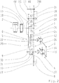
- Fig. 1 is a gear scheme of a transmission device 1 shown with secondary-coupled power split.
- a part of one of an existing as an internal combustion engine, preferably as a diesel engine, running engine 2 applied torque is in a first power branch 3 via a hydrostatic 4 and the other part of the torque in a second power branch 5 via a mechanical device 6 between a transmission input or a Transmission input shaft 7 and a transmission output or a transmission output shaft 8 feasible.
- the two power branches 3 and 5 are connected via a designed as a planetary gear summation gear in operative connection.
- a so-called vibration damper 11 is arranged, damped by means of which rotational irregularities in the field of the engine 2 and only a small proportion in the transmission device 1 and in the remaining part of the drive train of a vehicle or a construction vehicle be initiated.
- the transmission device 1 is designed with a driving range for forward and reverse travel, which can be switched on or off via direction switching elements KR and KV.
- the hydrostatic device 4 of the first power branch 3 comprises a pump 12 and a motor 13, which is operatively connected thereto via a hydraulic circuit (not shown in detail in the drawing), which are adjusted via a common yoke 14 and designed as bent axis units.
- the pump and the motor are independently adjustable and have another also suitable design.
- the transmission device 1 is formed as a countershaft transmission with a plurality of radially spaced countershafts 15 to 17, whereby the transmission device 1 in the axial direction has a small space requirement and in the vertical direction or in the vehicle vertical direction has a high space requirement, this for bridging a center distance between the output shaft 10 of the drive machine 2 and the transmission input shaft 7 and drive axles of a running example, as a forklift, wheel loader or the like vehicle can be bridged.
- Direction switching elements KV and KR are provided, by means of which can be switched between a forward drive mode and a reverse mode.
- a gear pump 18 On the direction of travel switching element KR for reverse gear associated countershaft 15, a gear pump 18 is arranged, which is driven as the countershaft 15 of the transmission input shaft 7 via a gear pair 19.
- the translation of the gear pair 19, which is formed from a first rotatably connected to the transmission input shaft 7 and designed as a spur gear 20 and a second gear 21, is such that the speed of the transmission input shaft 7 translated in the direction of the countershaft 15 in the fast becomes.
- the gear pump 18 in the present case runs at about 20% higher rotational speed than the engine 2 and can be made smaller in this embodiment of the gear device 1 in comparison to a gear pump arranged directly on the transmission input shaft 7.
- a further removal of power is possible in the region of the countershaft 15, which is provided for the operation of the working equipment of a preferably designed as a backhoe or the like construction vehicle or a stacker.
- a loading shovel, a lifting device of a truck or the like can be actuated, supplied via the countershaft and a driven over it further pump means with a corresponding working pressure.
- the power take-off is at the in Fig. 1 illustrated embodiment in the region of the countershaft 15 on the side facing away from the engine 2 side of the transmission device 1 to the transmission device 1 can be coupled via the need also any other consumer with torque acted upon.
- gear pump 18 in addition to the pump 12 and the motor 13 of the hydrostatic device 4 interconnecting hydraulic circuit, which is designed as a closed circuit, and a lubrication and cooling circuit with hydraulic fluid can be acted upon.
- direction of travel switching elements KR and KV can be acted upon by the transmission pump 18 with hydraulic working pressure and can be converted from an essentially open operating state into an essentially completely closed operating state.
- the trained as a simple planetary gear planetary gear device comprises three shafts 22 to 24, wherein a first shaft 22 is designed as a sun gear, a second shaft 23 as a planet carrier and a third shaft 24 as a ring gear.
- the transmission input shaft 7 can be brought into active connection with the planet carrier 23 of the planetary gear device 9 via the travel direction switching elements KR and KV, while the pump 12 of the hydrostatic device 4 is connected to the sun gear 22 of the planetary gear device 9.
- the displacement of the engine 13 is maximum while the displacement of the pump 12 is zero.
- the drive power of the drive machine 2 is then transmitted completely hydrostatically via the transmission device 1, this corresponds to a first limit of a driving range of the transmission device 1.
- the second limit of the driving range of the transmission device 1 is present when the pump 12 is stopped and the speed of the motor 13 is maximum, the displacement of the motor 13 is then equal to zero and the delivery volume of the pump 12 has its maximum value.
- the drive power of the drive machine 2 is transmitted completely mechanically between the transmission input shaft 7 and the transmission output shaft 8 via the transmission device 1.
- the second countershaft 16 represents the engine output shaft of the motor 13, which in addition to a gearwheel 27 of the second gearwheel pair 26 comprises a further fixed gear 28, which in turn meshes with a further fixed gear 29 of the transmission output shaft 8.
- the motor 13, which is operatively connected to the ring gear 24, is made larger than the pump 12 coupled to the sun gear 22, the motor 13 having a displacement of approximately 360 cm 3 / rev and the pump 12, for example, a delivery volume of 120 cm 3 / rev when a maximum power of the engine 2 is about 100 kW. Due to the different sized design of the motor 13 and the pump 12, the spread or a tensile force-speed ratio is greater compared to the same size executed hydro units of a hydrostatic device. In the region of the pump 12, only a small torque is to be supported due to the comparatively low maximum power of the drive machine 2, which is why the pump 12 can be designed with low performance. However, in order to be able to represent the tensile force in the area of the transmission output shaft 8 as large as possible, a correspondingly large-volume hydraulic motor is used in the present case.
- the different design of the motor 13 and the pump 12 is easy to implement when the transmission device 1 as shown only has a gear range and the pump 12 and the motor 13 are operated only in two so-called quadrant.
- hydrostatic units of steplessly power-split transmissions are operated in four quadrants due to the changing mode of operation with several transmission ranges, which is why they have to be made equally large.
- the transmission output shaft 8 of the transmission device 1 according to Fig. 1 not required and the output can be connected in a space-saving manner in the region of the second countershaft 16 with the transmission device 1.
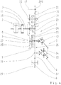
- Fig. 2 shows one Fig. 1 corresponding representation of a second embodiment of the transmission device 1, which only in partial areas of the first Embodiment according to Fig. 1 different. For this reason, for the sake of clarity in the following description, only the differences between the two exemplary embodiments will be discussed and with respect to the further mode of operation of the transmission device 1 according to FIG Fig. 2 to the above description Fig. 1 directed.
- the hydrostatic unit 4 is provided on one side of the planetary gear device 9, while the transmission input shaft 7 extends on the opposite side of the planetary gear device 9.
- the hydrostatic device 4 and the torque removal in the direction of a power take-off in the region of the first countershaft 15 are provided on the same side of the planetary gear device 9 and opposite to the transmission input shaft 7, whereby the transmission device 1 according to Fig. 2 characterized by a small space requirement in the axial direction.
- the transmission device 1 according to Fig. 2 executed with a staggered in the radial direction output, since a part of the transmission output torque via the off-axis provided for countershaft 16 transmission output shaft 8 and another part via a coaxial with the countershaft 16 and the output shaft of the motor 13 arranged further transmission output shaft 30 from the transmission device 1 is feasible ,
- the further transmission output shaft 30 is in the present case via a designed as a frictional clutch switching element 31 with the second countershaft 16 operatively connected, whereby the feasible on the other transmission output shaft 30 part of the transmission output torque of the transmission device 1 in addition depending on the transmission capacity of the switching element 31 is variable.
- Fig. 3 shows a wheel diagram of a third embodiment of the transmission device 1, which substantially according to the second embodiment of the transmission device 1 according to Fig. 2 equivalent.
- the transmission device 1 according to Fig. 3 is without the switching element 31 and the other transmission output shaft 30 of the transmission device 1 according to Fig. 2 executed.
- the transmission device 1 according to Fig. 3 is coupled only in the transmission output shaft 8 on the drive machine 2 side facing away from the transmission device 1 with the output, as is preferred in conventional stacker drives.
- the hydrostatic device 4 as in the second and third embodiment of the transmission device 1 according to Fig. 2 and Fig. 3 arranged on one side of the planetary gear device 9, while the transmission input shaft 7 is arranged on the other side of the planetary gear device 9 extending in the direction of the engine 2.
- the transmission device 1 corresponds to FIG Fig. 4 essentially the first embodiment of the transmission device 1 according to Fig. 1 ,
- the hydrostatic device 4 in installation position of the transmission device 1 vertically, ie seen in the vertical direction of the vehicle one above the other, or horizontally, that is seen iniserquer- or vehicle longitudinal direction side by side to arrange, the pump 12 at vertical arrangement is to be positioned over the motor 13.
- the hydrostatic device 4 according to Fig. 2 to Fig. 4 is a direct attachment of the prime mover 2 and the transmission device 1 possible.
Landscapes
- Engineering & Computer Science (AREA)
- General Engineering & Computer Science (AREA)
- Mechanical Engineering (AREA)
- Structure Of Transmissions (AREA)
- Arrangement Of Transmissions (AREA)
- Motor Power Transmission Devices (AREA)
Claims (12)
- Arrangement de boîte de transmission (1) comprenant un répartiteur de puissance accouplé du côté secondaire, une partie d'un couple appliqué pouvant être amené dans une première branche de puissance (3) au moins par le biais d'un dispositif hydrostatique (4) et l'autre partie du couple dans une deuxième branche de puissance (5) par le biais d'un dispositif mécanique (6) entre une entrée de boîte de transmission (7) et une sortie de boîte de transmission (8), le dispositif hydrostatique (4) de la première branche de puissance (3) comprenant au moins une pompe (12) et au moins un moteur (13) en liaison fonctionnelle avec celle-ci par le biais d'un circuit hydraulique, lesquels sont tous deux positionnables, les deux branches de puissance (3, 5) pouvant être additionnées par le biais d'un engrenage additionneur (9), l'engrenage additionneur (9) étant réalisé sous la forme d'un dispositif d'engrenage planétaire avec trois arbres (22, 23, 24), un premier arbre (23) du dispositif d'engrenage planétaire (9) se trouvant en liaison fonctionnelle avec l'entrée de boîte de transmission (7), un deuxième arbre (22) du dispositif d'engrenage planétaire (9) avec la pompe (12) et un troisième arbre (24) du dispositif d'engrenage planétaire (9) avec le moteur (13) et la sortie de boîte de transmission (8), et une seule plage de démultiplication étant présente, à l'intérieur de laquelle un rapport de démultiplication peut être varié en continu par le biais du dispositif hydrostatique (4),
caractérisé en ce que
le volume refoulé maximal de la pompe (12) est dimensionné plus petit que le volume absorbé maximal du moteur (13) et la pompe (12) et le moteur (13) peuvent être positionnés ensemble par le biais d'un étrier (14). - Arrangement de boîte de transmission selon la revendication 1, caractérisé en ce qu'au moins deux éléments de commutation du sens de la marche (KR, KV) se trouvent entre l'entrée de boîte de transmission (7) et l'engrenage additionneur (9), lesquels permettent de permuter entre un mode pour la marche avant et un mode pour la marche arrière.
- Arrangement de boîte de transmission selon la revendication 1, caractérisé en ce qu'au moins deux éléments de commutation du sens de la marche se trouvent entre une sortie de boîte de transmission et l'engrenage additionneur, lesquels permettent de permuter entre un mode pour la marche avant et un mode pour la marche arrière.
- Arrangement de boîte de transmission selon la revendication 1, caractérisé en ce que le premier arbre (23) du dispositif d'engrenage planétaire (9) est un porte-satellites, le deuxième arbre (22) du dispositif d'engrenage planétaire (9) une roue solaire et le troisième arbre (24) du dispositif d'engrenage planétaire (9) une couronne à denture intérieure.
- Arrangement de boîte de transmission selon l'une des revendications 1 à 4, caractérisé en ce qu'un volume absorbé du moteur (13) et un volume refoulé de la pompe (12) peuvent varier dans une plage de 0 % à 100 %, le couple appliqué au volume absorbé maximal du moteur (13) et au volume refoulé minimal de la pompe (12) étant acheminé entièrement par le biais de la première branche de puissance (3) qui possède le dispositif hydrostatique (4), et au volume absorbé minimal du moteur (13) et au volume refoulé maximal de la pompe (12) entièrement par le biais de la deuxième branche de puissance (5) qui possède le dispositif mécanique (6).
- Arrangement de boîte de transmission selon l'une des revendications 1 à 5, caractérisé en ce que le dispositif hydrostatique (4) et l'entrée de boîte de transmission (7) sont disposés du même côté de l'engrenage additionneur (9).
- Arrangement de boîte de transmission selon l'une des revendications 1 à 6, caractérisé en ce que le dispositif hydrostatique (4) est disposé d'un côté de l'engrenage additionneur (9) et l'entrée de boîte de transmission (7) de l'autre côté de l'engrenage additionneur (9).
- Arrangement de boîte de transmission selon l'une des revendications 1 à 7, caractérisé en ce que la sortie de boîte de transmission (8) se trouve au moins dans la zone d'un arbre (30) qui peut être amené en liaison fonctionnelle et/ou qui se trouve en liaison fonctionnelle avec un arbre de sortie (16) du moteur (13) .
- Arrangement de boîte de transmission selon l'une des revendications 1 à 8, caractérisé en ce que dans la zone de l'entrée de boîte de transmission (7), au moins une partie d'un couple appliqué du côté de l'entrée de boîte de transmission peut être dérivée en direction d'au moins un arbre (15, 17) supplémentaire pouvant être accouplé à une prise de force auxiliaire.
- Arrangement de boîte de transmission selon l'une des revendications 1 à 9, caractérisé en ce que la pompe (12) et le moteur (13), dans la position d'installation de l'arrangement de boîte de transmission (1) dans un véhicule, sont positionnés l'un par rapport à l'autre de manière adaptée à l'espace de montage existant.
- Arrangement de boîte de transmission selon l'une des revendications 1 à 10, caractérisé en ce que la pompe (12) et le moteur (13), dans la position d'installation de l'arrangement de boîte de transmission (1) dans un véhicule, sont disposés l'un au-dessus de l'autre dans le sens de la hauteur du véhicule ou sensiblement l'un à côté de l'autre dans le sens longitudinal du véhicule ou transversal du véhicule.
- Arrangement de boîte de transmission selon l'une des revendications 1 à 11, caractérisé en ce que les éléments de commutation du sens de la marche (KR, KV) sont réalisés sous la forme d'éléments de commutation de charge coopérant par friction.
Applications Claiming Priority (2)
| Application Number | Priority Date | Filing Date | Title |
|---|---|---|---|
| DE102013204747.9A DE102013204747A1 (de) | 2013-03-19 | 2013-03-19 | Getriebevorrichtung mit sekundär gekoppelter Leistungsverzweigung |
| PCT/EP2014/053051 WO2014146839A1 (fr) | 2013-03-19 | 2014-02-18 | Dispositif de transmission avec dérivation de puissance à couplage secondaire |
Publications (2)
| Publication Number | Publication Date |
|---|---|
| EP2976556A1 EP2976556A1 (fr) | 2016-01-27 |
| EP2976556B1 true EP2976556B1 (fr) | 2019-03-27 |
Family
ID=50115886
Family Applications (1)
| Application Number | Title | Priority Date | Filing Date |
|---|---|---|---|
| EP14705153.6A Active EP2976556B1 (fr) | 2013-03-19 | 2014-02-18 | Dispositif de transmission avec dérivation de puissance à couplage secondaire |
Country Status (6)
| Country | Link |
|---|---|
| US (1) | US9810305B2 (fr) |
| EP (1) | EP2976556B1 (fr) |
| JP (1) | JP6449233B2 (fr) |
| CN (1) | CN105190124B (fr) |
| DE (1) | DE102013204747A1 (fr) |
| WO (1) | WO2014146839A1 (fr) |
Families Citing this family (6)
| Publication number | Priority date | Publication date | Assignee | Title |
|---|---|---|---|---|
| US9404564B1 (en) | 2015-05-04 | 2016-08-02 | Caterpillar Inc. | Continuously variable transmission |
| DE102015223250A1 (de) * | 2015-11-25 | 2017-06-01 | Zf Friedrichshafen Ag | Leistungsverzweigungsgetriebe |
| CN106989155B (zh) * | 2017-05-02 | 2019-01-22 | 北京理工大学 | 一种装载机用液压机械复合无级传动装置 |
| CN107152510B (zh) * | 2017-05-02 | 2019-03-26 | 北京理工大学 | 装载机液压机械无级传动装置 |
| CN107143638B (zh) * | 2017-05-02 | 2019-03-26 | 北京理工大学 | 液压机械复合无级传动装置 |
| EP3584467B1 (fr) * | 2018-04-10 | 2021-11-17 | Beijing Institute Of Technology | Dispositif de transmission à variation continue mécanique hydraulique à trois étages de chargeur |
Citations (2)
| Publication number | Priority date | Publication date | Assignee | Title |
|---|---|---|---|---|
| DE19801766A1 (de) * | 1997-01-21 | 1998-07-23 | Honda Motor Co Ltd | Hydraulische und mechanische Getriebevorrichtung |
| WO2012006492A1 (fr) * | 2010-07-08 | 2012-01-12 | Parker-Hannifin Corporation | Moteur à répartition de puissance hydraulique à assistance de couple améliorée |
Family Cites Families (21)
| Publication number | Priority date | Publication date | Assignee | Title |
|---|---|---|---|---|
| DE1124369B (de) | 1959-08-29 | 1962-02-22 | Ford Werke Ag | Hydrostatisch-mechanisches Getriebe, insbesondere fuer Fahrzeuge |
| GB1161508A (en) * | 1965-09-17 | 1969-08-13 | Bosch Gmbh Robert | Improvements in Variable Ratio Transmission Systems |
| DE2335629C3 (de) * | 1973-07-13 | 1978-05-18 | Xaver Fendt & Co, 8952 Marktoberdorf | Hydrostatisch-mechanischer Antrieb fur land- und bauwirtschaftlich genutzte Fahrzeuge |
| DE3825409A1 (de) * | 1988-07-27 | 1990-02-01 | Man Nutzfahrzeuge Ag | Antriebseinrichtung, insbesondere fuer ein extremgelaendegaengiges radfahrzeug |
| JP2981980B2 (ja) * | 1996-02-22 | 1999-11-22 | 本田技研工業株式会社 | 油圧・機械式伝動装置 |
| JP2000016102A (ja) * | 1998-06-26 | 2000-01-18 | Kubota Corp | 油圧・機械式無段変速装置 |
| DE102004023628A1 (de) * | 2004-05-10 | 2005-12-08 | Zf Friedrichshafen Ag | Hydraulischer Antrieb für Mobilfahrzeuge |
| DE602006015054D1 (de) * | 2006-09-13 | 2010-08-05 | Schlumberger Technology Bv | Hydraulisches Frakturierungsverfahren und Frakturierungspumpenvorrichtung |
| DE102007018999A1 (de) | 2007-04-21 | 2008-10-30 | Zf Friedrichshafen Ag | Leistungsverzweigungsgetriebe |
| ATE534851T1 (de) * | 2007-10-02 | 2011-12-15 | Zahnradfabrik Friedrichshafen | Hydrostatisch-mechanisches leistungsverzweigungsgetriebe |
| WO2009047039A1 (fr) * | 2007-10-02 | 2009-04-16 | Zf Friedrichshafen Ag | Dispositif de réglage de la cylindrée de moteurs à pistons hydrauliques |
| CN101815884B (zh) * | 2007-10-02 | 2013-02-27 | Zf腓德烈斯哈芬股份公司 | 功率分流变速器 |
| ATE534850T1 (de) | 2007-10-02 | 2011-12-15 | Zahnradfabrik Friedrichshafen | Leistungsverzweigungsgetriebe |
| DE102007047194A1 (de) * | 2007-10-02 | 2009-04-09 | Zf Friedrichshafen Ag | Leistungsverzweigungsgetriebe |
| DE102008001326A1 (de) * | 2008-04-23 | 2009-10-29 | Zf Friedrichshafen Ag | Stufenlose Getriebevorrichtung eines Antriebsstranges eines Fahrzeuges |
| DE102008001613A1 (de) | 2008-05-07 | 2009-11-12 | Zf Friedrichshafen Ag | Getriebevorrichtung mit sekundär gekoppelter Leistungsverzweigung |
| DE102009031382A1 (de) * | 2009-07-01 | 2011-01-05 | Robert Bosch Gmbh | Antriebssystem und Verfahren zum Wechseln von Fahrbereichen des Antriebssystems |
| DE102009045087B4 (de) * | 2009-09-29 | 2022-06-15 | Zf Friedrichshafen Ag | Getriebevorrichtung mit Leistungsverzweigung |
| DE102010001697A1 (de) * | 2010-02-09 | 2011-08-11 | ZF Friedrichshafen AG, 88046 | Getriebevorrichtung mit Leistungsverzweigung |
| DE102010001698A1 (de) * | 2010-02-09 | 2011-08-11 | ZF Friedrichshafen AG, 88046 | Getriebevorrichtung mit Leistungsverzweigung |
| DE102010003941A1 (de) * | 2010-04-14 | 2011-10-20 | Zf Friedrichshafen Ag | Stufenlose Getriebevorrichtung mit Leistungsverzweigung |
-
2013
- 2013-03-19 DE DE102013204747.9A patent/DE102013204747A1/de not_active Withdrawn
-
2014
- 2014-02-18 US US14/777,866 patent/US9810305B2/en not_active Expired - Fee Related
- 2014-02-18 WO PCT/EP2014/053051 patent/WO2014146839A1/fr active Application Filing
- 2014-02-18 EP EP14705153.6A patent/EP2976556B1/fr active Active
- 2014-02-18 JP JP2016503582A patent/JP6449233B2/ja not_active Expired - Fee Related
- 2014-02-18 CN CN201480016522.9A patent/CN105190124B/zh not_active Expired - Fee Related
Patent Citations (2)
| Publication number | Priority date | Publication date | Assignee | Title |
|---|---|---|---|---|
| DE19801766A1 (de) * | 1997-01-21 | 1998-07-23 | Honda Motor Co Ltd | Hydraulische und mechanische Getriebevorrichtung |
| WO2012006492A1 (fr) * | 2010-07-08 | 2012-01-12 | Parker-Hannifin Corporation | Moteur à répartition de puissance hydraulique à assistance de couple améliorée |
Also Published As
| Publication number | Publication date |
|---|---|
| WO2014146839A1 (fr) | 2014-09-25 |
| CN105190124B (zh) | 2018-01-02 |
| CN105190124A (zh) | 2015-12-23 |
| EP2976556A1 (fr) | 2016-01-27 |
| DE102013204747A1 (de) | 2014-09-25 |
| JP6449233B2 (ja) | 2019-01-09 |
| US20160281831A1 (en) | 2016-09-29 |
| JP2016512871A (ja) | 2016-05-09 |
| US9810305B2 (en) | 2017-11-07 |
Similar Documents
| Publication | Publication Date | Title |
|---|---|---|
| EP2976556B1 (fr) | Dispositif de transmission avec dérivation de puissance à couplage secondaire | |
| EP2195553B1 (fr) | Transmission à répartition de puissance | |
| EP2207985B1 (fr) | Dispositif de transmission avec un variateur | |
| EP2195557B1 (fr) | Transmission à répartition de puissance | |
| EP2193287B1 (fr) | Transmission à répartition de puissance | |
| DE102008001613A1 (de) | Getriebevorrichtung mit sekundär gekoppelter Leistungsverzweigung | |
| EP1745230B1 (fr) | Mecanisme d'entrainement pour vehicule mobile | |
| EP3002146B1 (fr) | Systeme de transmission | |
| DE102009045087B4 (de) | Getriebevorrichtung mit Leistungsverzweigung | |
| EP2534395B1 (fr) | Dispositif de transmission a derivation de puissance | |
| DE102015218670A1 (de) | Stufenlos leistungsverzweigtes Getriebe mit einem Planetenradsatz und mit wenigstens drei Fahrbereichen | |
| EP2193289B1 (fr) | Dispositif de transmission à variation continue pour un véhicule | |
| DE102004001929A1 (de) | Hydrostatisch-mechanisches Leistungsverzweigungsgetriebe | |
| DE102008040443A1 (de) | Leistungsverzweigungsgetriebe | |
| EP2193291B1 (fr) | Transmission pour un véhicule, équipée d'un variateur | |
| DE102010001699A1 (de) | Getriebevorrichtung mit Leistungsverzweigung | |
| DE102013204746A1 (de) | Getriebevorrichtung mit sekundär gekoppelter Leistungsverzweigung | |
| DE102008040444A1 (de) | Leistungsverzweigungsgetriebe | |
| DE102008015276A1 (de) | Leistungsverzweigungsgetriebe | |
| DE102014220028A1 (de) | Getriebevorrichtung mit sekundär gekoppelter Leistungsverzweigung | |
| EP2193290B1 (fr) | Dispositif de transmission pour un véhicule | |
| DE102008040448A1 (de) | Getriebevorrichtung für ein Fahrzeug mit einem Variator, einer Planetengetriebeeinrichtung und einer Schaltgetriebeeinrichtung | |
| DE202022104125U1 (de) | Leistungsverzweigungsgetriebe | |
| AT503365B1 (de) | Variables doppelkupplungsgetriebe für kraftfahrzeuge | |
| DE102008040445A1 (de) | Getriebevorrichtung für ein Fahrzeug mit einem Variator und einer Planetengetriebeeinrichtung |
Legal Events
| Date | Code | Title | Description |
|---|---|---|---|
| PUAI | Public reference made under article 153(3) epc to a published international application that has entered the european phase |
Free format text: ORIGINAL CODE: 0009012 |
|
| 17P | Request for examination filed |
Effective date: 20150716 |
|
| AK | Designated contracting states |
Kind code of ref document: A1 Designated state(s): AL AT BE BG CH CY CZ DE DK EE ES FI FR GB GR HR HU IE IS IT LI LT LU LV MC MK MT NL NO PL PT RO RS SE SI SK SM TR |
|
| AX | Request for extension of the european patent |
Extension state: BA ME |
|
| DAX | Request for extension of the european patent (deleted) | ||
| STAA | Information on the status of an ep patent application or granted ep patent |
Free format text: STATUS: EXAMINATION IS IN PROGRESS |
|
| 17Q | First examination report despatched |
Effective date: 20170526 |
|
| GRAP | Despatch of communication of intention to grant a patent |
Free format text: ORIGINAL CODE: EPIDOSNIGR1 |
|
| STAA | Information on the status of an ep patent application or granted ep patent |
Free format text: STATUS: GRANT OF PATENT IS INTENDED |
|
| INTG | Intention to grant announced |
Effective date: 20180730 |
|
| GRAJ | Information related to disapproval of communication of intention to grant by the applicant or resumption of examination proceedings by the epo deleted |
Free format text: ORIGINAL CODE: EPIDOSDIGR1 |
|
| STAA | Information on the status of an ep patent application or granted ep patent |
Free format text: STATUS: EXAMINATION IS IN PROGRESS |
|
| GRAP | Despatch of communication of intention to grant a patent |
Free format text: ORIGINAL CODE: EPIDOSNIGR1 |
|
| STAA | Information on the status of an ep patent application or granted ep patent |
Free format text: STATUS: GRANT OF PATENT IS INTENDED |
|
| INTC | Intention to grant announced (deleted) | ||
| INTG | Intention to grant announced |
Effective date: 20190109 |
|
| GRAS | Grant fee paid |
Free format text: ORIGINAL CODE: EPIDOSNIGR3 |
|
| GRAA | (expected) grant |
Free format text: ORIGINAL CODE: 0009210 |
|
| STAA | Information on the status of an ep patent application or granted ep patent |
Free format text: STATUS: THE PATENT HAS BEEN GRANTED |
|
| AK | Designated contracting states |
Kind code of ref document: B1 Designated state(s): AL AT BE BG CH CY CZ DE DK EE ES FI FR GB GR HR HU IE IS IT LI LT LU LV MC MK MT NL NO PL PT RO RS SE SI SK SM TR |
|
| REG | Reference to a national code |
Ref country code: GB Ref legal event code: FG4D Free format text: NOT ENGLISH |
|
| REG | Reference to a national code |
Ref country code: CH Ref legal event code: EP |
|
| REG | Reference to a national code |
Ref country code: AT Ref legal event code: REF Ref document number: 1113485 Country of ref document: AT Kind code of ref document: T Effective date: 20190415 |
|
| REG | Reference to a national code |
Ref country code: IE Ref legal event code: FG4D Free format text: LANGUAGE OF EP DOCUMENT: GERMAN |
|
| REG | Reference to a national code |
Ref country code: DE Ref legal event code: R096 Ref document number: 502014011230 Country of ref document: DE |
|
| PG25 | Lapsed in a contracting state [announced via postgrant information from national office to epo] |
Ref country code: LT Free format text: LAPSE BECAUSE OF FAILURE TO SUBMIT A TRANSLATION OF THE DESCRIPTION OR TO PAY THE FEE WITHIN THE PRESCRIBED TIME-LIMIT Effective date: 20190327 Ref country code: FI Free format text: LAPSE BECAUSE OF FAILURE TO SUBMIT A TRANSLATION OF THE DESCRIPTION OR TO PAY THE FEE WITHIN THE PRESCRIBED TIME-LIMIT Effective date: 20190327 Ref country code: SE Free format text: LAPSE BECAUSE OF FAILURE TO SUBMIT A TRANSLATION OF THE DESCRIPTION OR TO PAY THE FEE WITHIN THE PRESCRIBED TIME-LIMIT Effective date: 20190327 Ref country code: NO Free format text: LAPSE BECAUSE OF FAILURE TO SUBMIT A TRANSLATION OF THE DESCRIPTION OR TO PAY THE FEE WITHIN THE PRESCRIBED TIME-LIMIT Effective date: 20190627 |
|
| REG | Reference to a national code |
Ref country code: NL Ref legal event code: MP Effective date: 20190327 |
|
| PG25 | Lapsed in a contracting state [announced via postgrant information from national office to epo] |
Ref country code: NL Free format text: LAPSE BECAUSE OF FAILURE TO SUBMIT A TRANSLATION OF THE DESCRIPTION OR TO PAY THE FEE WITHIN THE PRESCRIBED TIME-LIMIT Effective date: 20190327 Ref country code: GR Free format text: LAPSE BECAUSE OF FAILURE TO SUBMIT A TRANSLATION OF THE DESCRIPTION OR TO PAY THE FEE WITHIN THE PRESCRIBED TIME-LIMIT Effective date: 20190628 Ref country code: BG Free format text: LAPSE BECAUSE OF FAILURE TO SUBMIT A TRANSLATION OF THE DESCRIPTION OR TO PAY THE FEE WITHIN THE PRESCRIBED TIME-LIMIT Effective date: 20190627 Ref country code: RS Free format text: LAPSE BECAUSE OF FAILURE TO SUBMIT A TRANSLATION OF THE DESCRIPTION OR TO PAY THE FEE WITHIN THE PRESCRIBED TIME-LIMIT Effective date: 20190327 Ref country code: HR Free format text: LAPSE BECAUSE OF FAILURE TO SUBMIT A TRANSLATION OF THE DESCRIPTION OR TO PAY THE FEE WITHIN THE PRESCRIBED TIME-LIMIT Effective date: 20190327 Ref country code: LV Free format text: LAPSE BECAUSE OF FAILURE TO SUBMIT A TRANSLATION OF THE DESCRIPTION OR TO PAY THE FEE WITHIN THE PRESCRIBED TIME-LIMIT Effective date: 20190327 |
|
| PG25 | Lapsed in a contracting state [announced via postgrant information from national office to epo] |
Ref country code: ES Free format text: LAPSE BECAUSE OF FAILURE TO SUBMIT A TRANSLATION OF THE DESCRIPTION OR TO PAY THE FEE WITHIN THE PRESCRIBED TIME-LIMIT Effective date: 20190327 Ref country code: AL Free format text: LAPSE BECAUSE OF FAILURE TO SUBMIT A TRANSLATION OF THE DESCRIPTION OR TO PAY THE FEE WITHIN THE PRESCRIBED TIME-LIMIT Effective date: 20190327 Ref country code: PT Free format text: LAPSE BECAUSE OF FAILURE TO SUBMIT A TRANSLATION OF THE DESCRIPTION OR TO PAY THE FEE WITHIN THE PRESCRIBED TIME-LIMIT Effective date: 20190727 Ref country code: EE Free format text: LAPSE BECAUSE OF FAILURE TO SUBMIT A TRANSLATION OF THE DESCRIPTION OR TO PAY THE FEE WITHIN THE PRESCRIBED TIME-LIMIT Effective date: 20190327 Ref country code: IT Free format text: LAPSE BECAUSE OF FAILURE TO SUBMIT A TRANSLATION OF THE DESCRIPTION OR TO PAY THE FEE WITHIN THE PRESCRIBED TIME-LIMIT Effective date: 20190327 Ref country code: RO Free format text: LAPSE BECAUSE OF FAILURE TO SUBMIT A TRANSLATION OF THE DESCRIPTION OR TO PAY THE FEE WITHIN THE PRESCRIBED TIME-LIMIT Effective date: 20190327 Ref country code: SK Free format text: LAPSE BECAUSE OF FAILURE TO SUBMIT A TRANSLATION OF THE DESCRIPTION OR TO PAY THE FEE WITHIN THE PRESCRIBED TIME-LIMIT Effective date: 20190327 Ref country code: CZ Free format text: LAPSE BECAUSE OF FAILURE TO SUBMIT A TRANSLATION OF THE DESCRIPTION OR TO PAY THE FEE WITHIN THE PRESCRIBED TIME-LIMIT Effective date: 20190327 |
|
| PG25 | Lapsed in a contracting state [announced via postgrant information from national office to epo] |
Ref country code: PL Free format text: LAPSE BECAUSE OF FAILURE TO SUBMIT A TRANSLATION OF THE DESCRIPTION OR TO PAY THE FEE WITHIN THE PRESCRIBED TIME-LIMIT Effective date: 20190327 Ref country code: SM Free format text: LAPSE BECAUSE OF FAILURE TO SUBMIT A TRANSLATION OF THE DESCRIPTION OR TO PAY THE FEE WITHIN THE PRESCRIBED TIME-LIMIT Effective date: 20190327 |
|
| PG25 | Lapsed in a contracting state [announced via postgrant information from national office to epo] |
Ref country code: IS Free format text: LAPSE BECAUSE OF FAILURE TO SUBMIT A TRANSLATION OF THE DESCRIPTION OR TO PAY THE FEE WITHIN THE PRESCRIBED TIME-LIMIT Effective date: 20190727 |
|
| REG | Reference to a national code |
Ref country code: DE Ref legal event code: R097 Ref document number: 502014011230 Country of ref document: DE |
|
| PG25 | Lapsed in a contracting state [announced via postgrant information from national office to epo] |
Ref country code: DK Free format text: LAPSE BECAUSE OF FAILURE TO SUBMIT A TRANSLATION OF THE DESCRIPTION OR TO PAY THE FEE WITHIN THE PRESCRIBED TIME-LIMIT Effective date: 20190327 |
|
| PLBE | No opposition filed within time limit |
Free format text: ORIGINAL CODE: 0009261 |
|
| STAA | Information on the status of an ep patent application or granted ep patent |
Free format text: STATUS: NO OPPOSITION FILED WITHIN TIME LIMIT |
|
| PG25 | Lapsed in a contracting state [announced via postgrant information from national office to epo] |
Ref country code: SI Free format text: LAPSE BECAUSE OF FAILURE TO SUBMIT A TRANSLATION OF THE DESCRIPTION OR TO PAY THE FEE WITHIN THE PRESCRIBED TIME-LIMIT Effective date: 20190327 |
|
| 26N | No opposition filed |
Effective date: 20200103 |
|
| PG25 | Lapsed in a contracting state [announced via postgrant information from national office to epo] |
Ref country code: TR Free format text: LAPSE BECAUSE OF FAILURE TO SUBMIT A TRANSLATION OF THE DESCRIPTION OR TO PAY THE FEE WITHIN THE PRESCRIBED TIME-LIMIT Effective date: 20190327 |
|
| REG | Reference to a national code |
Ref country code: CH Ref legal event code: PL |
|
| GBPC | Gb: european patent ceased through non-payment of renewal fee |
Effective date: 20200218 |
|
| REG | Reference to a national code |
Ref country code: BE Ref legal event code: MM Effective date: 20200229 |
|
| PG25 | Lapsed in a contracting state [announced via postgrant information from national office to epo] |
Ref country code: MC Free format text: LAPSE BECAUSE OF FAILURE TO SUBMIT A TRANSLATION OF THE DESCRIPTION OR TO PAY THE FEE WITHIN THE PRESCRIBED TIME-LIMIT Effective date: 20190327 Ref country code: LU Free format text: LAPSE BECAUSE OF NON-PAYMENT OF DUE FEES Effective date: 20200218 |
|
| PG25 | Lapsed in a contracting state [announced via postgrant information from national office to epo] |
Ref country code: LI Free format text: LAPSE BECAUSE OF NON-PAYMENT OF DUE FEES Effective date: 20200229 Ref country code: CH Free format text: LAPSE BECAUSE OF NON-PAYMENT OF DUE FEES Effective date: 20200229 |
|
| PG25 | Lapsed in a contracting state [announced via postgrant information from national office to epo] |
Ref country code: FR Free format text: LAPSE BECAUSE OF NON-PAYMENT OF DUE FEES Effective date: 20200229 Ref country code: IE Free format text: LAPSE BECAUSE OF NON-PAYMENT OF DUE FEES Effective date: 20200218 Ref country code: GB Free format text: LAPSE BECAUSE OF NON-PAYMENT OF DUE FEES Effective date: 20200218 |
|
| PG25 | Lapsed in a contracting state [announced via postgrant information from national office to epo] |
Ref country code: BE Free format text: LAPSE BECAUSE OF NON-PAYMENT OF DUE FEES Effective date: 20200229 |
|
| REG | Reference to a national code |
Ref country code: AT Ref legal event code: MM01 Ref document number: 1113485 Country of ref document: AT Kind code of ref document: T Effective date: 20200218 |
|
| PG25 | Lapsed in a contracting state [announced via postgrant information from national office to epo] |
Ref country code: AT Free format text: LAPSE BECAUSE OF NON-PAYMENT OF DUE FEES Effective date: 20200218 |
|
| PGFP | Annual fee paid to national office [announced via postgrant information from national office to epo] |
Ref country code: DE Payment date: 20210202 Year of fee payment: 8 |
|
| PG25 | Lapsed in a contracting state [announced via postgrant information from national office to epo] |
Ref country code: MT Free format text: LAPSE BECAUSE OF FAILURE TO SUBMIT A TRANSLATION OF THE DESCRIPTION OR TO PAY THE FEE WITHIN THE PRESCRIBED TIME-LIMIT Effective date: 20190327 Ref country code: CY Free format text: LAPSE BECAUSE OF FAILURE TO SUBMIT A TRANSLATION OF THE DESCRIPTION OR TO PAY THE FEE WITHIN THE PRESCRIBED TIME-LIMIT Effective date: 20190327 |
|
| PG25 | Lapsed in a contracting state [announced via postgrant information from national office to epo] |
Ref country code: MK Free format text: LAPSE BECAUSE OF FAILURE TO SUBMIT A TRANSLATION OF THE DESCRIPTION OR TO PAY THE FEE WITHIN THE PRESCRIBED TIME-LIMIT Effective date: 20190327 |
|
| REG | Reference to a national code |
Ref country code: DE Ref legal event code: R119 Ref document number: 502014011230 Country of ref document: DE |
|
| PG25 | Lapsed in a contracting state [announced via postgrant information from national office to epo] |
Ref country code: DE Free format text: LAPSE BECAUSE OF NON-PAYMENT OF DUE FEES Effective date: 20220901 |