EP2975357B1 - Vorrichtung mit einer abtasteinheit und einer montagehilfe und verfahren zur montage der abtasteinheit - Google Patents
Vorrichtung mit einer abtasteinheit und einer montagehilfe und verfahren zur montage der abtasteinheit Download PDFInfo
- Publication number
- EP2975357B1 EP2975357B1 EP15166912.4A EP15166912A EP2975357B1 EP 2975357 B1 EP2975357 B1 EP 2975357B1 EP 15166912 A EP15166912 A EP 15166912A EP 2975357 B1 EP2975357 B1 EP 2975357B1
- Authority
- EP
- European Patent Office
- Prior art keywords
- scanning unit
- mounting aid
- reference element
- mounting
- rotational axis
- Prior art date
- Legal status (The legal status is an assumption and is not a legal conclusion. Google has not performed a legal analysis and makes no representation as to the accuracy of the status listed.)
- Active
Links
Images

Classifications
-
- G—PHYSICS
- G01—MEASURING; TESTING
- G01D—MEASURING NOT SPECIALLY ADAPTED FOR A SPECIFIC VARIABLE; ARRANGEMENTS FOR MEASURING TWO OR MORE VARIABLES NOT COVERED IN A SINGLE OTHER SUBCLASS; TARIFF METERING APPARATUS; MEASURING OR TESTING NOT OTHERWISE PROVIDED FOR
- G01D5/00—Mechanical means for transferring the output of a sensing member; Means for converting the output of a sensing member to another variable where the form or nature of the sensing member does not constrain the means for converting; Transducers not specially adapted for a specific variable
- G01D5/12—Mechanical means for transferring the output of a sensing member; Means for converting the output of a sensing member to another variable where the form or nature of the sensing member does not constrain the means for converting; Transducers not specially adapted for a specific variable using electric or magnetic means
- G01D5/244—Mechanical means for transferring the output of a sensing member; Means for converting the output of a sensing member to another variable where the form or nature of the sensing member does not constrain the means for converting; Transducers not specially adapted for a specific variable using electric or magnetic means influencing characteristics of pulses or pulse trains; generating pulses or pulse trains
- G01D5/24428—Error prevention
- G01D5/24433—Error prevention by mechanical means
- G01D5/24442—Error prevention by mechanical means by mounting means
Definitions
- the present invention relates to a device with a scanning unit and a mounting aid according to the preamble of claim 1.
- the invention relates to a method for mounting a scanning unit according to claim 10.
- Position measuring devices are used in particular in processing machines for measuring the relative position of a tool with respect to a workpiece to be machined, in coordinate measuring machines for determining the position and dimensions of test objects as well as in the semiconductor industry, for example in wafer steppers and bonders.
- the scale is attached directly to the drive unit (eg linear motor) or the scale is attached to a component driven by the drive unit.
- a scanning unit of the position measuring device is arranged on another machine part whose position is to be measured.
- a generic scanning and position measuring device is for example in the EP 0 397 970 A1 described.
- an assembly aid is provided as a component between the object to be measured and the scanning unit.
- This mounting aid comprises a pin about which the scanning unit can be rotated or pivoted by means of adjusting screws with eccentric lugs.
- This interposition of a mounting aid requires a relatively large amount of space. Furthermore, the demands on the manufacturing tolerances are large in order to achieve a backlash-free adjustment.
- An assembly aid for adjusting the scanning unit is also in the DE 37 40 744 A1 disclosed.
- This mounting aid has a mounting plane and two adjustment screws.
- the scanning unit can be pushed in four directions by means of the two adjusting screws on the mounting plane of the mounting aid in the radial and tangential direction.
- the present invention has for its object to provide a device with a scanning unit of a position measuring device and a mounting aid, with a simple assembly with high accuracy is possible.
- the invention has for its object to provide a method for the simplest possible assembly, with the required accuracy of the assignment between the scanning unit and scale is made possible.
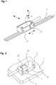
- the illustrated position measuring device is designed as a length measuring device and comprises a scale 1 and a relative thereto in the measuring direction X movable scanning unit 2.
- the scale 1 carries an incremental measuring graduation 11, which can be scanned by a detector unit of the scanning unit 2.
- the detector unit When scanning the measuring graduation 11, the detector unit generates in a known manner position-dependent electrical periodic measuring signals.
- the scanning unit 2 comprises a transparent for the scanning beam scanning window 23, which points in the direction of the scanned in the position measurement scale 1 and therefore in the FIG. 1 is not visible.
- the views according to the Figures 2 . 4 . 5 and 7 without scale 1 show the scanning window 23 of the scanning unit. 2
- the direction Z is thus the direction in which the scale 1 is scanned by the scanning unit 2.
- the angle R is also referred to as the yaw angle or moiré angle, and the setting of this angle is called the moire setting. This angular assignment must be set individually for each combination of scanning unit 2 and scale 1.
- the required angular position or rotational position of the scanning unit 2 that is to say the angle R, is set by means of an assembly aid 3.
- the electrical scanning signals of the scanning device 2 are monitored, wherein the amplitude and / or the mutual phase position of a plurality of the scanning signals is a measure of the quality of the scanning signals and thus the required assignment between the scanning unit 2 and scale 1.
- the mounting aid 3 is designed such that the scanning unit 2 is rotatable about a rotation axis D of a reference element 4.
- the rotation axis D runs parallel to the in FIG. 1 drawn axis Z.
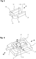
- the FIG. 2 shows the scanning unit 2 in a first assembly step.
- the reference element 4 is a pin which is fixedly attached to the object 5 to be measured. This reference element 4 forms the axis of rotation D about which the scanning unit 2 is rotated to adjust the moire angle.
- the pin can also be used a sleeve.
- the scanning unit 2 is designed to form a form fit with the reference element 4 by conditioning, which captivates the scanning unit 2 relative to the reference element 4 in directions X, Y transversely to the axis of rotation D.
- This positive connection is formed in an advantageous manner by providing a recess 22 in an outer wall 21 of the scanning unit 2.
- the recess 22 is formed in the example as a V-shaped groove or notch, in which the outer surface of the circular reference element 4 is inserted and with the Outer surface of the circular reference element 4 forms a pivot bearing.
- the recess 22 is as close as possible to the center of gravity of the scanning, that is arranged in the shortest possible distance to the scanning window 23.
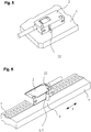
- FIG. 3 Mounting aid 3 shown in detail provided, which is adapted to hold the scanning unit 2 to the mounting aid 3 such that the scanning unit 2 is pivotable about the axis of rotation D of the reference element 4 by means of the mounting aid 3 carrying it.
- This holder is made such that the mounting aid 3 urges the scanning unit 2 to the reference element 4. This ensures a play-free installation of the scanning unit 2 to the reference element 4.
- the holder is also such that the mounting aid 3 with the scanning unit 2 forms a rotationally fixed form-fit, which ensures that the scanning unit 2 is rotatable about the axis of rotation D by means of the mounting aid 3.
- this further assembly step is shown, in which the mounting aid 3 is pushed in the direction + X on the scanning unit 2 and the mounting aid 3, the scanning unit 2 urges on the pin-shaped reference element 4 and the non-rotatable positive connection between the mounting aid 3 and the scanning unit 2 is made.
- the mounting aid 3 has two opposing arms 31, 32 which surround the scanning unit 2 and between which the scanning unit 2 is received and held by clamping. To generate the clamping force, at least one of these two arms 31, 32 is elastically resilient, so that the scanning unit 2 is urged against the reference element 4.
- the arms 31 and 32 generate a force F1 and counterforce F2 such that on the one hand the scanning unit 2 is held in a clamping manner on the mounting aid 3 and on the other hand the scanning unit 2 is urged against the reference element 4.
- F1 and counterforce F2 such that on the one hand the scanning unit 2 is held in a clamping manner on the mounting aid 3 and on the other hand the scanning unit 2 is urged against the reference element 4.
- the mounting aid 3 is fixed in a form-fitting manner on the reference element 4 in the illustrated assembly position such that a stationary bondage in the directions X, Y, ie transversely to the axis of rotation D is ensured.
- This positive connection is formed by the circular outer surface of the reference element 4 and a corresponding Recess 33 in the mounting aid 3, in particular again in the form of a V-groove or a notch.
- the scanning unit 2 is thus clamped between the reference element 4 and the arm 32 of the mounting aid 3 and the reference element 4 is clamped between the scanning unit 2 and the arm 31 of the mounting aid 3.
- the scanning window 23 and thus also the recess 22 of the scanning unit 2 is not centered (viewed in the direction X) arranged.
- a further recess 35 is present in the mounting aid 3. If the mounting aid 3 is now in the in FIG. 4 drawn -X direction, the recess 35 acts positively with the reference element 4 together.
- the handling of the scanner 2 is improved during assembly and the adjustment process.
- the handling can be further improved by targeted measures.
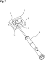
- this can be provided in the assembly aid 3, at least one hole 34 which extends transversely to the axis of rotation D.
- This hole 34 is dimensioned such that a tool 6, for example a screwdriver, is inserted as accurately as possible in order to pivot the mounting aid 3 with the scanning unit 2 clamped therein about the rotation axis D in a particularly sensitive manner, such as FIG. 7 shows.
- Such a configuration is particularly suitable for cramped installation conditions. It may be advantageous to provide a plurality of such holes 34 which are accessible from different sides or directions within the XY plane.
- the mounting aid 3 is designed such that it can be removed from the scanning unit 2 after the adjustment and assembly of the scanning unit 2 to the object 5 to be measured.
- the mounting aid 3 can in a direction perpendicular to the axis of rotation D, advantageously in the measuring direction X, overcoming the clamping force of the two arms 31, 32 of the Scanning unit 2 and are subtracted from the reference element 4. Should it be necessary for reasons of space, the reference element 4 can also be removed from the object 5 to be measured.
- the fixed after the adjustment on the object to be measured 5 fixed scanning unit 2 is in FIG. 5 shown.
- the fixed attachment to the object to be measured 5 can be done for example by screws, not shown, or by gluing.
- FIG. 6 shows a further possibility for the formation of the reference element.
- a reference element 4.1 is provided on the object 7 to be measured, to which the scale 1 is attached.
- This reference element 4.1 can now be used on the one hand as a stop for aligning the scale 1 and on the other hand also for the inventive adjustment of the scanning unit. 2
- This mounting aid 3.1 in turn has two arms 31, 32 which form a gap in which on the one hand the scanning unit 2 is held clamped and on the other hand, the scanning unit 2 is urged to the reference element 4.
- a handle 9 is integrally formed in this assembly aid 3.1.
- This handle 9 is designed as extensions of the arms 31, 32.
- this handle 9 facilitate the adjustment of the mounting aid 3.1 by this forms a handle and a lever and on the other hand, so that the clamping force can be lifted to a removal of the mounting aid 3.1 of the scanning unit 2 to facilitate.
- the function is comparable to a clothespin.
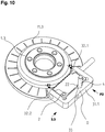
- the scanning unit 2 is provided, which a measuring graduation 11.3 of a scale 1.3 scans.
- the scale 1.3 is designed as a partial disk, alternatively, it may also be formed in the form of a drum, wherein the measuring graduation can then be provided on the end face or the lateral surface.
- the scanning unit 2 is to be mounted in these cases during assembly to an object to be measured with the accuracy specified by the manufacturer.
- an assembly aid 3.3 is provided, with which the scanning unit 2 is rotatable about the axis of rotation D of the reference element 4.
- An outer wall of the scanning unit 2 has a recess 22 in the form of a notch, which forms a positive connection with the circular surface of the reference element 4, as already explained above.
- the arms 31.1, 32.1, 32.2 of the mounting aid 3.3 are configured somewhat differently for the clamping engagement of the scanning unit 2.
- the force F1, F2 for clamping holding the scanning unit 2 to the mounting aid 3.3 and for urging the scanning unit 2 to the reference element 4 is initiated by the two arm-shaped sections 32.1 and 32.2.
- the arm 31.1 acts in this case as a counter-holder, on the one hand to push the scanning unit 2 without play on one side of the reference element 4 and on the other hand to push the mounting aid 3.3 backlash to the opposite side of the reference element 4.
- clamping force F1, F2 is initiated by the means of assembly aid 3, 3.1, 3.3 mentioned in claim 1.
- These means introduce a force which urges the scanning unit 2 to the reference element 4, 4.1, the term urging having the meaning of pressing.
- the means are elastic or resilient means to ensure a play-free contact even during rotation of the scanning unit 2 to the reference element 4, 4.1.
- the force is realized by an elastic or resilient design of at least one of the arms 31, 32, 31.1, 32.1, 32.2 of the mounting aid 3, 3.1, 3.3, which the scanning unit 2 by clamping the mounting aid 3, 3.1, 3.3 holds.
- the scanning unit 2 comprises the scanning window 23 which is transparent to the scanning beam and points in the direction of the scale 1 to be scanned during the position measurement.
- the invention is not limited thereto and is also successfully implemented in inductive, magnetic or capacitive sensing principles.
Landscapes
- Physics & Mathematics (AREA)
- General Physics & Mathematics (AREA)
- Transmission And Conversion Of Sensor Element Output (AREA)
- Optical Transform (AREA)
- A Measuring Device Byusing Mechanical Method (AREA)
- Length Measuring Devices With Unspecified Measuring Means (AREA)
- Mounting And Adjusting Of Optical Elements (AREA)
- Mechanical Optical Scanning Systems (AREA)
- Optical Systems Of Projection Type Copiers (AREA)
Applications Claiming Priority (1)
| Application Number | Priority Date | Filing Date | Title |
|---|---|---|---|
| DE102014213955.4A DE102014213955A1 (de) | 2014-07-17 | 2014-07-17 | Vorrichtung mit einer Abtasteinheit und einer Montagehilfe und Verfahren zur Montage der Abtasteinheit |
Publications (3)
| Publication Number | Publication Date |
|---|---|
| EP2975357A2 EP2975357A2 (de) | 2016-01-20 |
| EP2975357A3 EP2975357A3 (de) | 2016-01-27 |
| EP2975357B1 true EP2975357B1 (de) | 2017-07-12 |
Family
ID=53051746
Family Applications (1)
| Application Number | Title | Priority Date | Filing Date |
|---|---|---|---|
| EP15166912.4A Active EP2975357B1 (de) | 2014-07-17 | 2015-05-08 | Vorrichtung mit einer abtasteinheit und einer montagehilfe und verfahren zur montage der abtasteinheit |
Country Status (6)
Families Citing this family (2)
| Publication number | Priority date | Publication date | Assignee | Title |
|---|---|---|---|---|
| ES2853486T3 (es) * | 2018-10-31 | 2021-09-16 | Heidenhain Gmbh Dr Johannes | Unidad de exploración de un dispositivo para medida de la posición |
| EP4481331A1 (de) | 2023-06-21 | 2024-12-25 | AMO Automatisierung Messtechnik Optik GmbH | Abtasteinheit einer positionsmesseinrichtung |
Family Cites Families (14)
| Publication number | Priority date | Publication date | Assignee | Title |
|---|---|---|---|---|
| US4115925A (en) * | 1977-05-16 | 1978-09-26 | Malak Stephen P | Shaft aligner |
| DE3542042C1 (de) * | 1985-11-28 | 1987-01-02 | Daimler Benz Ag | Faseroptischer Sensor zur Erfassung der Bewegung oder Position eines Bauteils |
| SE455536B (sv) * | 1986-12-02 | 1988-07-18 | Leine & Linde Ab | Forfarande och anordning for overforing av justerat lege fran justerfixtur till yttre drivenhet for en vinkelmetanordning |
| EP0369570A1 (en) * | 1988-11-16 | 1990-05-23 | Intel Gasgards Private Limited | Improvements in and relating to sensors |
| DE3915679A1 (de) | 1989-05-13 | 1990-11-15 | Heidenhain Gmbh Dr Johannes | Positionsmesseinrichtung mit einer justiervorrichtung |
| JPH10197802A (ja) * | 1997-01-10 | 1998-07-31 | Nikon Corp | ステ−ジ |
| GB2350429B (en) * | 1999-05-28 | 2003-11-12 | Taylor Hobson Ltd | A metrological instrument |
| DE19949044B4 (de) * | 1999-10-11 | 2004-05-27 | Leica Microsystems Wetzlar Gmbh | Vorrichtung zur Feinfokussierung eines Objektives in einem optischen Sytstem und Koordinaten-Messgerät mit einer Vorrichtung zur Feinfokussierung eines Objektivs |
| JP3887188B2 (ja) * | 2001-08-08 | 2007-02-28 | 株式会社ミツトヨ | プローブのアライメント調整装置、その装置を備えた測定機およびプローブのアライメント調整方法 |
| JP4005472B2 (ja) * | 2002-10-10 | 2007-11-07 | ソニーマニュファクチュアリングシステムズ株式会社 | 位置検出装置 |
| JP2007127530A (ja) * | 2005-11-04 | 2007-05-24 | Fuji Electric Fa Components & Systems Co Ltd | 光学式リニアエンコーダの組立調整システム及び調整方法 |
| DE102010030948A1 (de) * | 2010-07-05 | 2012-01-05 | Dr. Johannes Heidenhain Gmbh | Positionsmesssystem und Verfahren zur Montage |
| DE102010052503B4 (de) * | 2010-11-26 | 2012-06-21 | Wenzel Scantec Gmbh | Verfahren zur Steuerung eines Koordinatenmessgeräts sowie Koordinatenmessgerät |
| TWI482923B (zh) * | 2012-10-05 | 2015-05-01 | Aopen Inc | 定位裝置及定位方法 |
-
2014
- 2014-07-17 DE DE102014213955.4A patent/DE102014213955A1/de not_active Withdrawn
-
2015
- 2015-05-08 ES ES15166912.4T patent/ES2643832T3/es active Active
- 2015-05-08 EP EP15166912.4A patent/EP2975357B1/de active Active
- 2015-06-12 SG SG10201504669QA patent/SG10201504669QA/en unknown
- 2015-07-07 JP JP2015136011A patent/JP6271474B2/ja active Active
- 2015-07-17 CN CN201510421327.0A patent/CN105277084B/zh active Active
Non-Patent Citations (1)
| Title |
|---|
| None * |
Also Published As
| Publication number | Publication date |
|---|---|
| EP2975357A3 (de) | 2016-01-27 |
| JP6271474B2 (ja) | 2018-01-31 |
| CN105277084B (zh) | 2020-01-17 |
| JP2016024189A (ja) | 2016-02-08 |
| SG10201504669QA (en) | 2016-02-26 |
| DE102014213955A1 (de) | 2016-01-21 |
| CN105277084A (zh) | 2016-01-27 |
| EP2975357A2 (de) | 2016-01-20 |
| ES2643832T3 (es) | 2017-11-24 |
Similar Documents
| Publication | Publication Date | Title |
|---|---|---|
| EP2274627B1 (de) | Mikromechanisches bauelement und verfahren zum betrieb eines mikromechanischen bauelements | |
| EP2093537B1 (de) | Verfahren und Vorrichtung zur Ermittlung einer Ausrichtung von zwei drehbar gelagerten Maschinenteilen | |
| EP3047240B1 (de) | Verfahren zum herstellen einer magneteinheit für eine sensoreinrichtung zum erfassen einer einen rotationszustand einer lenkwelle eines kraftfahrzeugs charakterisierenden messgrösse, magneteinheit, sensoreinrichtung und kraftfahrzeug | |
| EP1353150B1 (de) | Drehwinkelmesseinrichtung | |
| EP0506913B1 (de) | Vorrichtung zum positionieren eines sensors | |
| EP1895277A1 (de) | Rotary encoder with mounting aid | |
| DE10022555A1 (de) | Winkelmeßeinrichtung | |
| WO2010000541A2 (de) | Vorrichtung zur klemmenden befestigung eines massstabs | |
| EP2975357B1 (de) | Vorrichtung mit einer abtasteinheit und einer montagehilfe und verfahren zur montage der abtasteinheit | |
| DE102012202683A1 (de) | Drehgeber | |
| WO2002040947A1 (de) | Positionsmesssystem und montageverfahren dafür | |
| DE102006036746B4 (de) | Positionsmesseinrichtung | |
| EP2767806B1 (de) | Winkelmesseinrichtung | |
| DE19816827B4 (de) | Vormontierte Winkelmeßvorrichtung | |
| DE102012003963B4 (de) | Kodierer mit Beständigkeit gegen Vibration und Erschütterung | |
| DE202006010183U1 (de) | Winkelmesseinrichtung und Messanordnung mit einer derartigen Winkelmesseinrichtung | |
| EP1666848B1 (de) | Körper mit einer Winkelskalierung | |
| DE102011084411B4 (de) | Winkelmesseinrichtung | |
| EP1764584B1 (de) | Befestigung eines Trägers einer Massverkörperung | |
| DE102018206967B4 (de) | Verfahren und vorrichtung zur anordnung von kleindimensionierten bauteilen an baugruppen mit exakter ausrichtung der bauteile an der baugruppe | |
| CH718956A1 (de) | Werkzeugmaschine mit Kalibriervorrichtung zur Kalibrierung eines Einzentriersensors. | |
| DE10310369C5 (de) | Optisches Meßsystem | |
| DE102007059362A1 (de) | Sensoranordnung mit Positioniermodul | |
| EP2434260B1 (de) | Positionsmesssystem und Verfahren zur Montage | |
| EP1557643A1 (de) | Drehwinkelmesseinrichtung |
Legal Events
| Date | Code | Title | Description |
|---|---|---|---|
| PUAL | Search report despatched |
Free format text: ORIGINAL CODE: 0009013 |
|
| PUAI | Public reference made under article 153(3) epc to a published international application that has entered the european phase |
Free format text: ORIGINAL CODE: 0009012 |
|
| 17P | Request for examination filed |
Effective date: 20150508 |
|
| AK | Designated contracting states |
Kind code of ref document: A2 Designated state(s): AL AT BE BG CH CY CZ DE DK EE ES FI FR GB GR HR HU IE IS IT LI LT LU LV MC MK MT NL NO PL PT RO RS SE SI SK SM TR |
|
| AX | Request for extension of the european patent |
Extension state: BA ME |
|
| AK | Designated contracting states |
Kind code of ref document: A3 Designated state(s): AL AT BE BG CH CY CZ DE DK EE ES FI FR GB GR HR HU IE IS IT LI LT LU LV MC MK MT NL NO PL PT RO RS SE SI SK SM TR |
|
| AX | Request for extension of the european patent |
Extension state: BA ME |
|
| RIC1 | Information provided on ipc code assigned before grant |
Ipc: G01D 5/00 20060101ALI20151221BHEP Ipc: G01B 5/00 20060101AFI20151221BHEP Ipc: G01D 5/244 20060101ALI20151221BHEP Ipc: G01B 5/24 20060101ALI20151221BHEP |
|
| 17Q | First examination report despatched |
Effective date: 20160418 |
|
| RBV | Designated contracting states (corrected) |
Designated state(s): AL AT BE BG CH CY CZ DE DK EE ES FI FR GB GR HR HU IE IS IT LI LT LU LV MC MK MT NL NO PL PT RO RS SE SI SK SM TR |
|
| GRAP | Despatch of communication of intention to grant a patent |
Free format text: ORIGINAL CODE: EPIDOSNIGR1 |
|
| INTG | Intention to grant announced |
Effective date: 20170223 |
|
| GRAS | Grant fee paid |
Free format text: ORIGINAL CODE: EPIDOSNIGR3 |
|
| GRAA | (expected) grant |
Free format text: ORIGINAL CODE: 0009210 |
|
| AK | Designated contracting states |
Kind code of ref document: B1 Designated state(s): AL AT BE BG CH CY CZ DE DK EE ES FI FR GB GR HR HU IE IS IT LI LT LU LV MC MK MT NL NO PL PT RO RS SE SI SK SM TR |
|
| REG | Reference to a national code |
Ref country code: GB Ref legal event code: FG4D Free format text: NOT ENGLISH |
|
| REG | Reference to a national code |
Ref country code: CH Ref legal event code: EP Ref country code: CH Ref legal event code: NV Representative=s name: ICB INGENIEURS CONSEILS EN BREVETS SA, CH |
|
| REG | Reference to a national code |
Ref country code: AT Ref legal event code: REF Ref document number: 908765 Country of ref document: AT Kind code of ref document: T Effective date: 20170715 |
|
| REG | Reference to a national code |
Ref country code: IE Ref legal event code: FG4D Free format text: LANGUAGE OF EP DOCUMENT: GERMAN |
|
| REG | Reference to a national code |
Ref country code: DE Ref legal event code: R096 Ref document number: 502015001409 Country of ref document: DE |
|
| REG | Reference to a national code |
Ref country code: NL Ref legal event code: MP Effective date: 20170712 |
|
| REG | Reference to a national code |
Ref country code: ES Ref legal event code: FG2A Ref document number: 2643832 Country of ref document: ES Kind code of ref document: T3 Effective date: 20171124 |
|
| REG | Reference to a national code |
Ref country code: LT Ref legal event code: MG4D |
|
| PG25 | Lapsed in a contracting state [announced via postgrant information from national office to epo] |
Ref country code: SE Free format text: LAPSE BECAUSE OF FAILURE TO SUBMIT A TRANSLATION OF THE DESCRIPTION OR TO PAY THE FEE WITHIN THE PRESCRIBED TIME-LIMIT Effective date: 20170712 Ref country code: NO Free format text: LAPSE BECAUSE OF FAILURE TO SUBMIT A TRANSLATION OF THE DESCRIPTION OR TO PAY THE FEE WITHIN THE PRESCRIBED TIME-LIMIT Effective date: 20171012 Ref country code: HR Free format text: LAPSE BECAUSE OF FAILURE TO SUBMIT A TRANSLATION OF THE DESCRIPTION OR TO PAY THE FEE WITHIN THE PRESCRIBED TIME-LIMIT Effective date: 20170712 Ref country code: NL Free format text: LAPSE BECAUSE OF FAILURE TO SUBMIT A TRANSLATION OF THE DESCRIPTION OR TO PAY THE FEE WITHIN THE PRESCRIBED TIME-LIMIT Effective date: 20170712 Ref country code: FI Free format text: LAPSE BECAUSE OF FAILURE TO SUBMIT A TRANSLATION OF THE DESCRIPTION OR TO PAY THE FEE WITHIN THE PRESCRIBED TIME-LIMIT Effective date: 20170712 Ref country code: LT Free format text: LAPSE BECAUSE OF FAILURE TO SUBMIT A TRANSLATION OF THE DESCRIPTION OR TO PAY THE FEE WITHIN THE PRESCRIBED TIME-LIMIT Effective date: 20170712 |
|
| PG25 | Lapsed in a contracting state [announced via postgrant information from national office to epo] |
Ref country code: BG Free format text: LAPSE BECAUSE OF FAILURE TO SUBMIT A TRANSLATION OF THE DESCRIPTION OR TO PAY THE FEE WITHIN THE PRESCRIBED TIME-LIMIT Effective date: 20171012 Ref country code: GR Free format text: LAPSE BECAUSE OF FAILURE TO SUBMIT A TRANSLATION OF THE DESCRIPTION OR TO PAY THE FEE WITHIN THE PRESCRIBED TIME-LIMIT Effective date: 20171013 Ref country code: IS Free format text: LAPSE BECAUSE OF FAILURE TO SUBMIT A TRANSLATION OF THE DESCRIPTION OR TO PAY THE FEE WITHIN THE PRESCRIBED TIME-LIMIT Effective date: 20171112 Ref country code: PL Free format text: LAPSE BECAUSE OF FAILURE TO SUBMIT A TRANSLATION OF THE DESCRIPTION OR TO PAY THE FEE WITHIN THE PRESCRIBED TIME-LIMIT Effective date: 20170712 Ref country code: RS Free format text: LAPSE BECAUSE OF FAILURE TO SUBMIT A TRANSLATION OF THE DESCRIPTION OR TO PAY THE FEE WITHIN THE PRESCRIBED TIME-LIMIT Effective date: 20170712 Ref country code: LV Free format text: LAPSE BECAUSE OF FAILURE TO SUBMIT A TRANSLATION OF THE DESCRIPTION OR TO PAY THE FEE WITHIN THE PRESCRIBED TIME-LIMIT Effective date: 20170712 |
|
| REG | Reference to a national code |
Ref country code: DE Ref legal event code: R097 Ref document number: 502015001409 Country of ref document: DE |
|
| PG25 | Lapsed in a contracting state [announced via postgrant information from national office to epo] |
Ref country code: DK Free format text: LAPSE BECAUSE OF FAILURE TO SUBMIT A TRANSLATION OF THE DESCRIPTION OR TO PAY THE FEE WITHIN THE PRESCRIBED TIME-LIMIT Effective date: 20170712 Ref country code: CZ Free format text: LAPSE BECAUSE OF FAILURE TO SUBMIT A TRANSLATION OF THE DESCRIPTION OR TO PAY THE FEE WITHIN THE PRESCRIBED TIME-LIMIT Effective date: 20170712 Ref country code: RO Free format text: LAPSE BECAUSE OF FAILURE TO SUBMIT A TRANSLATION OF THE DESCRIPTION OR TO PAY THE FEE WITHIN THE PRESCRIBED TIME-LIMIT Effective date: 20170712 |
|
| PLBE | No opposition filed within time limit |
Free format text: ORIGINAL CODE: 0009261 |
|
| STAA | Information on the status of an ep patent application or granted ep patent |
Free format text: STATUS: NO OPPOSITION FILED WITHIN TIME LIMIT |
|
| PG25 | Lapsed in a contracting state [announced via postgrant information from national office to epo] |
Ref country code: IT Free format text: LAPSE BECAUSE OF FAILURE TO SUBMIT A TRANSLATION OF THE DESCRIPTION OR TO PAY THE FEE WITHIN THE PRESCRIBED TIME-LIMIT Effective date: 20170712 Ref country code: SM Free format text: LAPSE BECAUSE OF FAILURE TO SUBMIT A TRANSLATION OF THE DESCRIPTION OR TO PAY THE FEE WITHIN THE PRESCRIBED TIME-LIMIT Effective date: 20170712 Ref country code: EE Free format text: LAPSE BECAUSE OF FAILURE TO SUBMIT A TRANSLATION OF THE DESCRIPTION OR TO PAY THE FEE WITHIN THE PRESCRIBED TIME-LIMIT Effective date: 20170712 Ref country code: SK Free format text: LAPSE BECAUSE OF FAILURE TO SUBMIT A TRANSLATION OF THE DESCRIPTION OR TO PAY THE FEE WITHIN THE PRESCRIBED TIME-LIMIT Effective date: 20170712 |
|
| 26N | No opposition filed |
Effective date: 20180413 |
|
| PG25 | Lapsed in a contracting state [announced via postgrant information from national office to epo] |
Ref country code: SI Free format text: LAPSE BECAUSE OF FAILURE TO SUBMIT A TRANSLATION OF THE DESCRIPTION OR TO PAY THE FEE WITHIN THE PRESCRIBED TIME-LIMIT Effective date: 20170712 |
|
| PG25 | Lapsed in a contracting state [announced via postgrant information from national office to epo] |
Ref country code: MT Free format text: LAPSE BECAUSE OF FAILURE TO SUBMIT A TRANSLATION OF THE DESCRIPTION OR TO PAY THE FEE WITHIN THE PRESCRIBED TIME-LIMIT Effective date: 20170712 |
|
| REG | Reference to a national code |
Ref country code: BE Ref legal event code: MM Effective date: 20180531 |
|
| PG25 | Lapsed in a contracting state [announced via postgrant information from national office to epo] |
Ref country code: MC Free format text: LAPSE BECAUSE OF FAILURE TO SUBMIT A TRANSLATION OF THE DESCRIPTION OR TO PAY THE FEE WITHIN THE PRESCRIBED TIME-LIMIT Effective date: 20170712 |
|
| REG | Reference to a national code |
Ref country code: IE Ref legal event code: MM4A |
|
| PG25 | Lapsed in a contracting state [announced via postgrant information from national office to epo] |
Ref country code: LU Free format text: LAPSE BECAUSE OF NON-PAYMENT OF DUE FEES Effective date: 20180508 |
|
| PG25 | Lapsed in a contracting state [announced via postgrant information from national office to epo] |
Ref country code: FR Free format text: LAPSE BECAUSE OF NON-PAYMENT OF DUE FEES Effective date: 20180531 Ref country code: IE Free format text: LAPSE BECAUSE OF NON-PAYMENT OF DUE FEES Effective date: 20180508 |
|
| PG25 | Lapsed in a contracting state [announced via postgrant information from national office to epo] |
Ref country code: BE Free format text: LAPSE BECAUSE OF NON-PAYMENT OF DUE FEES Effective date: 20180531 |
|
| PG25 | Lapsed in a contracting state [announced via postgrant information from national office to epo] |
Ref country code: TR Free format text: LAPSE BECAUSE OF FAILURE TO SUBMIT A TRANSLATION OF THE DESCRIPTION OR TO PAY THE FEE WITHIN THE PRESCRIBED TIME-LIMIT Effective date: 20170712 |
|
| PG25 | Lapsed in a contracting state [announced via postgrant information from national office to epo] |
Ref country code: PT Free format text: LAPSE BECAUSE OF FAILURE TO SUBMIT A TRANSLATION OF THE DESCRIPTION OR TO PAY THE FEE WITHIN THE PRESCRIBED TIME-LIMIT Effective date: 20170712 |
|
| PG25 | Lapsed in a contracting state [announced via postgrant information from national office to epo] |
Ref country code: HU Free format text: LAPSE BECAUSE OF FAILURE TO SUBMIT A TRANSLATION OF THE DESCRIPTION OR TO PAY THE FEE WITHIN THE PRESCRIBED TIME-LIMIT; INVALID AB INITIO Effective date: 20150508 Ref country code: MK Free format text: LAPSE BECAUSE OF NON-PAYMENT OF DUE FEES Effective date: 20170712 Ref country code: CY Free format text: LAPSE BECAUSE OF FAILURE TO SUBMIT A TRANSLATION OF THE DESCRIPTION OR TO PAY THE FEE WITHIN THE PRESCRIBED TIME-LIMIT Effective date: 20170712 |
|
| PG25 | Lapsed in a contracting state [announced via postgrant information from national office to epo] |
Ref country code: AL Free format text: LAPSE BECAUSE OF FAILURE TO SUBMIT A TRANSLATION OF THE DESCRIPTION OR TO PAY THE FEE WITHIN THE PRESCRIBED TIME-LIMIT Effective date: 20170712 |
|
| REG | Reference to a national code |
Ref country code: AT Ref legal event code: MM01 Ref document number: 908765 Country of ref document: AT Kind code of ref document: T Effective date: 20200508 |
|
| PG25 | Lapsed in a contracting state [announced via postgrant information from national office to epo] |
Ref country code: AT Free format text: LAPSE BECAUSE OF NON-PAYMENT OF DUE FEES Effective date: 20200508 |
|
| PGFP | Annual fee paid to national office [announced via postgrant information from national office to epo] |
Ref country code: DE Payment date: 20250521 Year of fee payment: 11 |
|
| PGFP | Annual fee paid to national office [announced via postgrant information from national office to epo] |
Ref country code: GB Payment date: 20250527 Year of fee payment: 11 Ref country code: ES Payment date: 20250627 Year of fee payment: 11 |
|
| PGFP | Annual fee paid to national office [announced via postgrant information from national office to epo] |
Ref country code: CH Payment date: 20250601 Year of fee payment: 11 |