EP2975309B1 - Pressdichtung mit Elastomerkörper - Google Patents
Pressdichtung mit Elastomerkörper Download PDFInfo
- Publication number
- EP2975309B1 EP2975309B1 EP14177270.7A EP14177270A EP2975309B1 EP 2975309 B1 EP2975309 B1 EP 2975309B1 EP 14177270 A EP14177270 A EP 14177270A EP 2975309 B1 EP2975309 B1 EP 2975309B1
- Authority
- EP
- European Patent Office
- Prior art keywords
- press plate
- nut
- elastomer body
- press
- recess
- Prior art date
- Legal status (The legal status is an assumption and is not a legal conclusion. Google has not performed a legal analysis and makes no representation as to the accuracy of the status listed.)
- Active
Links
Images

Classifications
-
- F—MECHANICAL ENGINEERING; LIGHTING; HEATING; WEAPONS; BLASTING
- F16—ENGINEERING ELEMENTS AND UNITS; GENERAL MEASURES FOR PRODUCING AND MAINTAINING EFFECTIVE FUNCTIONING OF MACHINES OR INSTALLATIONS; THERMAL INSULATION IN GENERAL
- F16L—PIPES; JOINTS OR FITTINGS FOR PIPES; SUPPORTS FOR PIPES, CABLES OR PROTECTIVE TUBING; MEANS FOR THERMAL INSULATION IN GENERAL
- F16L5/00—Devices for use where pipes, cables or protective tubing pass through walls or partitions
- F16L5/02—Sealing
- F16L5/08—Sealing by means of axial screws compressing a ring or sleeve
-
- F—MECHANICAL ENGINEERING; LIGHTING; HEATING; WEAPONS; BLASTING
- F16—ENGINEERING ELEMENTS AND UNITS; GENERAL MEASURES FOR PRODUCING AND MAINTAINING EFFECTIVE FUNCTIONING OF MACHINES OR INSTALLATIONS; THERMAL INSULATION IN GENERAL
- F16J—PISTONS; CYLINDERS; SEALINGS
- F16J15/00—Sealings
- F16J15/02—Sealings between relatively-stationary surfaces
- F16J15/021—Sealings between relatively-stationary surfaces with elastic packing
- F16J15/028—Sealings between relatively-stationary surfaces with elastic packing the packing being mechanically expanded against the sealing surface
-
- F—MECHANICAL ENGINEERING; LIGHTING; HEATING; WEAPONS; BLASTING
- F16—ENGINEERING ELEMENTS AND UNITS; GENERAL MEASURES FOR PRODUCING AND MAINTAINING EFFECTIVE FUNCTIONING OF MACHINES OR INSTALLATIONS; THERMAL INSULATION IN GENERAL
- F16L—PIPES; JOINTS OR FITTINGS FOR PIPES; SUPPORTS FOR PIPES, CABLES OR PROTECTIVE TUBING; MEANS FOR THERMAL INSULATION IN GENERAL
- F16L21/00—Joints with sleeve or socket
- F16L21/02—Joints with sleeve or socket with elastic sealing rings between pipe and sleeve or between pipe and socket, e.g. with rolling or other prefabricated profiled rings
- F16L21/04—Joints with sleeve or socket with elastic sealing rings between pipe and sleeve or between pipe and socket, e.g. with rolling or other prefabricated profiled rings in which sealing rings are compressed by axially-movable members
- F16L21/045—Joints with sleeve or socket with elastic sealing rings between pipe and sleeve or between pipe and socket, e.g. with rolling or other prefabricated profiled rings in which sealing rings are compressed by axially-movable members the members passing through the sealing rings
-
- F—MECHANICAL ENGINEERING; LIGHTING; HEATING; WEAPONS; BLASTING
- F16—ENGINEERING ELEMENTS AND UNITS; GENERAL MEASURES FOR PRODUCING AND MAINTAINING EFFECTIVE FUNCTIONING OF MACHINES OR INSTALLATIONS; THERMAL INSULATION IN GENERAL
- F16L—PIPES; JOINTS OR FITTINGS FOR PIPES; SUPPORTS FOR PIPES, CABLES OR PROTECTIVE TUBING; MEANS FOR THERMAL INSULATION IN GENERAL
- F16L55/00—Devices or appurtenances for use in, or in connection with, pipes or pipe systems
-
- H—ELECTRICITY
- H02—GENERATION; CONVERSION OR DISTRIBUTION OF ELECTRIC POWER
- H02G—INSTALLATION OF ELECTRIC CABLES OR LINES, OR OF COMBINED OPTICAL AND ELECTRIC CABLES OR LINES
- H02G3/00—Installations of electric cables or lines or protective tubing therefor in or on buildings, equivalent structures or vehicles
- H02G3/22—Installations of cables or lines through walls, floors or ceilings, e.g. into buildings
-
- Y—GENERAL TAGGING OF NEW TECHNOLOGICAL DEVELOPMENTS; GENERAL TAGGING OF CROSS-SECTIONAL TECHNOLOGIES SPANNING OVER SEVERAL SECTIONS OF THE IPC; TECHNICAL SUBJECTS COVERED BY FORMER USPC CROSS-REFERENCE ART COLLECTIONS [XRACs] AND DIGESTS
- Y10—TECHNICAL SUBJECTS COVERED BY FORMER USPC
- Y10S—TECHNICAL SUBJECTS COVERED BY FORMER USPC CROSS-REFERENCE ART COLLECTIONS [XRACs] AND DIGESTS
- Y10S277/00—Seal for a joint or juncture
- Y10S277/935—Seal made of a particular material
- Y10S277/944—Elastomer or plastic
Definitions
- the present invention relates to a compression seal with an elastomeric body for sealing engagement with a duct passed therethrough.
- Press seals of this type in addition to the elastomeric body further on a press plate and a clamping bolt.
- the press plate By tightening the clamping bolt, the press plate can be pressed onto the elastomer body, whereby it is compressed in the direction of the line.
- the elastomeric body expands perpendicular thereto or seals against the passed-through conduit and, for example, the soffit of a wall opening.
- the US 5,340,123 A shows a link chain press seal with injection molded compacts formed three-dimensionally with a reinforcing rib structure.
- the clamping bolts provided for bracing the press seal each interact with a flange nut embedded in a respective compact.
- DE 196 51 659 C1 discloses a press seal with injection molded clamping rings. These are in turn provided with a ribbing structure for mechanical reinforcement.
- the present invention has for its object to provide an advantageous press seal and an advantageous method for their preparation.
- the positive locking keeps the proximal portion of the nut and thus the entire nut "against rotation", thus blocking a rotational movement of the nut about the axis of rotation.
- the "rotation axis” defines a reference system and results as the axis about which the threaded portion rotates when screwing, so for example as an axis of rotational symmetry of the cylinder, in whose lateral surface, the grooves of the thread (the threaded portion) are introduced.
- the flange projects beyond the recess "outwards", which refers to the axis of rotation as the center, that is, perpendicularly away from the latter.
- the term “the recess” refers to the section of a passage opening in the press plate, in which the positive connection with the nut exists. If, for example, the nut does not extend as far as an end face of the pressing plate which is proximal to the elastomer body, the proximal section of the passage opening adjoining the nut then no longer counts as a recess; On the other hand, with a correspondingly large nut, the entire passage opening can also be a recess.
- the flange projecting outwardly of the recess preferably has a contact surface on the pressing plate itself in order to transmit the force during clamping of the clamping bolt, specifically on a side of the pressing plate opposite to the elastomer body.
- a washer could also be provided and the flange therefore not directly abut the press plate, but nevertheless transmit a force to this.
- the corresponding abutment then prevents, as soon as the flange rests against the pressure plate, slipping of the nut along the axis of rotation in the direction of the elastomer body, for example, already during the tightening of the clamping bolt and in particular during clamping.
- a further advantage of the combination of features according to the invention can also be that the size of the contact surface between the flange and the press plate can in principle be freely selected, that is, for example, a correspondingly large contact surface can also be set.
- This can offer advantages in terms of a uniform force transmission to the press plate and thus also on the elastomer body; a uniform compression is desirable, for example, the material stress and tightness.
- the mother would find with their face an abutment on the press plate (which provides a simpler mother would allow).
- the resulting corresponding contact surface would be determined on the one hand by the size of the mother; On the other hand, it would be compared to the present approach also closer to the axis of rotation, so the power transmission more concentrated and thus less evenly distributed.
- the press plate with the nut inserted is located on an end side of the elastomer body (frontally relative to the axis of rotation parallel directions), and preferably at the opposite end face another press plate is provided.
- the elastomer body is then compressed during bracing so between the two press plates with respect to the axis of rotation parallel directions so that it applies perpendicularly sealingly to the lines, for example, a wall in a wall or floor element, so about the reveal of a through hole or a casing.
- a "pressing plate" arranged on an end face of the elastomer body may, for example, also be provided in several parts, that is to say constructed from a plurality of press plate parts. This may be the case with a press seal for retrofitting on the pipe.
- the passage opening for the line is then connected to an outer sealing surface of the elastomer body via a parting line extending through the elastomer body, so that the elastomeric body can be unfolded and placed on the line or inserted; the parting line may extend, for example, parallel to the axis of rotation and perpendicular thereto through the elastomeric body.
- the press plate is then preferably divided according to the parting line in the elastomer body so that the press seal can be unfolded in the whole, so the elastomer body mounted thereon press plate.
- the provided for the line through hole in the elastomeric body may for example also be equipped with a sleeve or a plurality of nested sleeves, so that the passage opening can be adjusted by removing a sleeve to a larger diameter pipe.
- a plurality of sleeves are connected by material bridges with each other or the rest of the elastomer body, wherein a material bridge can be separated to remove the respective sleeve.
- the sleeves can for example all provided on the same elastomeric body and be separated from each other parallel to the axis of rotation about this circumferentially extending sections (apart from preferably frontal material bridges).
- the elastomeric body may also be multi-part, wherein a first elastomeric body part has a plurality of sleeves and also a second elastomeric body part has a plurality of sleeves; the first and second elastomeric body portions are then assembled such that a sleeve of the first elastomeric body portion is disposed in the space between two sleeves of the second elastomeric body portion, and vice versa.
- the first elastomeric body part is then constructed comb-like in a sectional plane containing the center axis of the conduit, the comb teeth corresponding to the sleeves and the sleeves of the other elastomer body part (or other elastomer body parts) are arranged in the spaces between the teeth.
- the shells provided in the intermediate spaces may also be connected in a comb-like manner, so that the elastomeric body in this picture corresponds to two combs pushed into one another with the tines.
- a corresponding elastomer body part with sufficiently large gaps can namely also be produced in a molding process, for example by injection molding, pressing or transfer molding.
- the recess is bounded perpendicular to the axis of rotation to the outside by a skirt surface of the pressure plate; this skirt surface holds the elastomeric body proximal portion of the nut form-fitting.
- the edging surface passes directly into a face surface of the pressing plate that is distal to the elastomer body, and the flange abuts against this distal end face.
- no recess in the elastomeric body opposite (to the distal end) of the press plate is provided, in which the flange is seated; in general, such a recess could in fact be provided, for instance milled in.
- a "direct" transition is preferred, ie, at most a section of convex curvature is found between the border surface and the (distal) end face.
- the two faces adjoin one another in an edge running around the axis of rotation. It is then preferably not provided chamfering, which may also be advantageous in terms of a possible large-scale system between the flange and press plate.
- the distal end face is flat in its surface area, that is, the pressure plate is comparatively simple, which may facilitate, for example, handling during assembly.
- the pressing plate is formed in its surface area as a whole flat plate. "In their area” means apart from possibly the surface enclosing outer edges, which may be bent, for example, in the case of a thin sheet for mechanical reinforcement.
- the surface directions are preferably perpendicular to the axis of rotation.
- the distal end face is particularly preferably flat in its entirety (ie up to the outer edges) and is furthermore preferably perpendicular to the axis of rotation.
- the pressing plate is a total (up to the outer edges) a flat plate, so there are no bent edges.
- a metal is preferred for the press plate, for example, galvanized steels, low or high alloy stainless steels.
- a metal can offer advantages in terms of rigidity, which may be of interest in particular with regard to the preferably flat construction.
- the pressing plate is machined out of a metal sheet, for example by punching, cutting, in particular laser cutting, or milling.
- a thin sheet with a thickness taken in the direction of the axis of rotation of less than 3 mm may be provided, which is then stiffened by, for example, bending up the edges, a thickness of at least 3 mm is preferred, with at least 4 mm wider and at least 5 mm are particularly preferred.
- Possible upper limits may be, for example, at most 2 cm, 1.5 cm or 1 cm; an upper limit may be advantageous in terms of, for example, the material consumption and also its processability.
- the skirt surface which laterally delimits the recess, extends only parallel to the axis of rotation and without offset, so that it does not run conically, for example, in sections.
- the skirt surface seen in the direction of the axis of rotation has a polygonal profile with preferably equally long edges, such as a square, hexagonal or octagonal profile.
- the elastomeric body proximal portion of the nut preferably has a complementary profile.
- the entire passage opening in the pressure plate is limited by an exclusively parallel to the axis of rotation without offset extending skirt surface. It may therefore extend the elastomeric body proximal portion of the nut through the entire press plate, so they fully enforce.
- this passage opening is preferably delimited by a passage opening bordering surface which extends without offset parallel to the rotation axis through the pressure plate.
- Off-set means, as above, that the extension is free of diameter or, in more general terms, distance jumps perpendicular to the axis of rotation.
- a corresponding passage opening can advantageously be introduced into the press plate in a simplified manner, for example in comparison to the milling of a passage opening with a distance / diameter jump.
- the inventive provision of the nut with flange advantageously allows such a simple configuration of the through hole, because the flange is preferably applied to an end face.
- the flange is provided completely circumferential with respect to a circulation around the axis of rotation, it projects beyond the recess so in relation to all directions perpendicular to the axis of rotation of this away to the outside. This may be of interest with regard to, for example, maximizing the contact surface between the flange and the press plate or even as uniform a transmission of the contact pressure as possible.
- a contact surface area (the contact surface between flange and press plate) is at least 1.1 times, more preferably at least 1.2 times, particularly preferably at least 1.3 times, an end face area that the Elastomer body proximal (the flange opposite) end face of the mother has. Possible upper limits may be, for example, at most 3, 2.5 or 2 times. In this context, the "proximal end face" of the nut is considered, which would find an abutment on a surface perpendicular to the axis of rotation.
- the clamping bolt at its end screwed into the nut opposite end has a screw head with a screw head drive, preferably with an internal screw head drive, such as an internal hexagon or Torxprofil.
- the clamping bolt can then be rotated via the screw head drive, for example, when screwing into the nut in the course of production and / or for pressing the pressure plate on the elastomer body.
- a set screw could be screwed into the nut with a flange and placed on the mother with flange opposite end of a clamping nut.
- a clamping bolt with screw head is preferred.
- a hole into which the threaded portion of the tensioning bolt is threaded extends as the through-hole passing through the nut. More preferably, then the entire through hole is provided with an internal thread, so the mother is not limited to screwing the clamping bolt and thus the distortion of the press seal.
- a preferred clamping bolt further comprises a thread-free portion therebetween, against which the elastomeric body in the clamped state sealingly applies.
- the unthreaded the section may extend over at least 10%, 20%, and 30%, and independently thereof, at most 80%, 70%, 60%, and 50% of the span length taken along the axis of rotation (the values are in the Their order of preference is increasingly preferred).
- the invention also relates to a production method.
- the clamping bolt is introduced when the nut is set in the recess and elastomeric body and pressure plate are in contact with each other.
- a receiving device is provided for assembly, in which the nut is located with the then positively held, proximal portion facing upwards;
- the mother is inserted in accordance with the receiving device.
- the press plate is placed on the receiving device in such a way that the nut sits positively in the recess.
- the elastomeric body is placed on the press plate with the now already positively held therein nut, and it is then screwed the clamping bolt, preferably after placing another press plate on the elastomer body.
- the individual parts can advantageously be "stacked” on one another, that is, stacked one after the other, without the press seal (or the respectively already assembled part thereof) having to be reoriented therebetween.
- “Hang up” means "following the direction of gravity".
- the through hole can advantageously be provided correspondingly simply with through-hole bordering surface extending exclusively parallel and without offset from the axis of rotation.
- the through hole or the recess is introduced by means of laser cutting, which in comparison to a milling offer, for example, the throughput or the costs relating to advantages, that is to say may be of particular interest in mass production.
- the invention also relates to the use of a corresponding compression seal for sealing a power, gas, water, heat, telecommunications, signal or data line, which passes through a wall or floor element, preferably a building wall or a building floor.
- the press seal can for example be placed in a core hole directly against the wall or floor element or used in a cast-in casing.
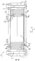
- Fig. 1 shows the press seal 1 according to the invention in a sectional side view.
- the elastomeric body 2 which is bordered by two press plates 3.
- the two press plates 3 are connected to each other via clamping bolts 4 such that they can be moved towards each other by tightening the clamping bolt 4, so that the elastomeric body 2 is compressed therebetween and consequently applies sealingly to the soffit of a passage opening and a line passed therethrough (not shown).
- the elastomer body 2 is composed of two elastomer body parts 2a, b, each of which provides a plurality of shells 6a, b circulating around the through-opening 5 for the line.
- each elastomeric body part 2a, b by itself in a molding process, such as by pressing in a mold or injection molding, because the spaces between the shells 6a, b of the respective elastomer body part 2a, b are sufficiently large.
- the shells 6b of the other elastomer body part 2b are then arranged in the composite elastomer body 2, and vice versa.
- the shells 6a, b can be removed to adapt the passage opening 5 on lines of different outer diameter.
- a respective material bridge 7a, b provided at the axial end of the respective shell 6a, b is separated.
- the material bridges 7a, b are frontally over circumferential notches 8a, b marked, whereby at the same time reduces the material thickness and the removal is facilitated.
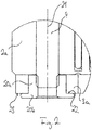
- Fig. 2 shows in a detailed view of the present invention relative to the pressing plate 3a mounted clamping bolt 4.
- the clamping bolt 4 is screwed with its threaded portion in a nut 20.
- This nut 20 is seated with a portion 20a proximal to the elastomer body 2 in a form-fitting manner in a recess in the press plate 3a.
- a elastomeric body 2 distal portion 20b of the nut 20 has a flange. This projects beyond the recess to the outside, and relative to directions perpendicularly away from a rotation axis 21 about which the clamping bolt 4 is screwed into the nut 20.
- the flange bears with a contact surface 22 on the elastomeric body 2 distal end face 23 of the press plate 3a. If the clamping bolt 4 is further screwed into the nut 20 for tensioning the elastomer body 2, the nut 20 is held against rotation in the recess of the press plate 3a on the one hand; On the other hand, the elastomeric body 2 distal portion 20b forms with the flange an abutment, so the press plate 3a is pressed onto the elastomer body 2. The elastomeric body 2 is compressed in the direction of the axis of rotation 4 and expands perpendicular to it to apply to the line and soffit.
- Fig. 3 shows the press seal 1 according to the invention in a plan view, namely looking at the press plate 3b.
- the respective clamping bolts 4 are supported in each case via a screw head 29 with external hex, and stored on a respective washer.
- the passage opening 5 is, as described above, comprised of a series of shells 6a, b for diameter adaptation, the circumferential notches 8b being visible in the plan view.
- vent holes 30 are shown in this plan view, via which during the assembly of the two elastomer body parts 2a, b located in the respective spaces between the shells 6a, b air can escape.
Landscapes
- Engineering & Computer Science (AREA)
- General Engineering & Computer Science (AREA)
- Mechanical Engineering (AREA)
- Architecture (AREA)
- Civil Engineering (AREA)
- Structural Engineering (AREA)
- Gasket Seals (AREA)
- Bolts, Nuts, And Washers (AREA)
- Casting Or Compression Moulding Of Plastics Or The Like (AREA)
Priority Applications (9)
| Application Number | Priority Date | Filing Date | Title |
|---|---|---|---|
| EP14177270.7A EP2975309B1 (de) | 2014-07-16 | 2014-07-16 | Pressdichtung mit Elastomerkörper |
| PL14177270T PL2975309T3 (pl) | 2014-07-16 | 2014-07-16 | Uszczelnienie dociskowe z korpusem elastomerowym |
| CN201580049989.8A CN107002912B (zh) | 2014-07-16 | 2015-07-14 | 具有弹性体的压力密封件 |
| CA2954208A CA2954208C (en) | 2014-07-16 | 2015-07-14 | Press seal having an elastomer body |
| PCT/EP2015/066055 WO2016008879A1 (de) | 2014-07-16 | 2015-07-14 | Pressdichtung mit elastomerkörper |
| KR1020177003933A KR102402553B1 (ko) | 2014-07-16 | 2015-07-14 | 탄성중합체 본체를 가지는 압축 시일 |
| US15/326,376 US9915379B2 (en) | 2014-07-16 | 2015-07-14 | Press seal having an elastomer body |
| JP2017502215A JP6602839B2 (ja) | 2014-07-16 | 2015-07-14 | エラストマー体を有する加圧式シール |
| AU2015289202A AU2015289202B2 (en) | 2014-07-16 | 2015-07-14 | Compression seal having an elastomer body |
Applications Claiming Priority (1)
| Application Number | Priority Date | Filing Date | Title |
|---|---|---|---|
| EP14177270.7A EP2975309B1 (de) | 2014-07-16 | 2014-07-16 | Pressdichtung mit Elastomerkörper |
Publications (2)
| Publication Number | Publication Date |
|---|---|
| EP2975309A1 EP2975309A1 (de) | 2016-01-20 |
| EP2975309B1 true EP2975309B1 (de) | 2017-06-14 |
Family
ID=51178777
Family Applications (1)
| Application Number | Title | Priority Date | Filing Date |
|---|---|---|---|
| EP14177270.7A Active EP2975309B1 (de) | 2014-07-16 | 2014-07-16 | Pressdichtung mit Elastomerkörper |
Country Status (9)
| Country | Link |
|---|---|
| US (1) | US9915379B2 (enExample) |
| EP (1) | EP2975309B1 (enExample) |
| JP (1) | JP6602839B2 (enExample) |
| KR (1) | KR102402553B1 (enExample) |
| CN (1) | CN107002912B (enExample) |
| AU (1) | AU2015289202B2 (enExample) |
| CA (1) | CA2954208C (enExample) |
| PL (1) | PL2975309T3 (enExample) |
| WO (1) | WO2016008879A1 (enExample) |
Families Citing this family (5)
| Publication number | Priority date | Publication date | Assignee | Title |
|---|---|---|---|---|
| DE102017119933A1 (de) * | 2017-08-30 | 2019-02-28 | Airbus Operations Gmbh | Faserverbundbauteil mit einer Elastomerdichtung sowie ein Verfahren zu dessen Herstellung |
| CN110541984A (zh) * | 2019-07-23 | 2019-12-06 | 铜山县恒丰机械有限公司 | 一种工程机械的密封多结构灵活调节工程管道连接件 |
| SE543692C2 (en) * | 2019-10-23 | 2021-06-08 | Roxtec Ab | Compressible round seal for a lead-through maintaining the shape of a rectangular through hole when compressed |
| SE544601C2 (en) * | 2021-01-04 | 2022-09-20 | Roxtec Ab | A transit for passing cables and/or pipes through a partition opening and use of such a transit |
| CN113108133B (zh) * | 2021-05-27 | 2023-05-30 | 广船国际有限公司 | 一种密封连接结构 |
Citations (7)
| Publication number | Priority date | Publication date | Assignee | Title |
|---|---|---|---|---|
| US5340123A (en) | 1991-09-13 | 1994-08-23 | Thunderline Corporation | Pressure hardware for a modular inter-wall elastomer seal |
| DE19651659C1 (de) | 1996-12-12 | 1998-05-07 | Helmut Hiendl | Dichtungselement für eine Wanddurchführung |
| EP1164677A1 (de) | 2000-06-17 | 2001-12-19 | Hauff-Technik GmbH & Co. KG | Dichtpackung zum Hindurchführen von Leitungen durch eine Wand |
| EP1843071A1 (de) | 2006-04-03 | 2007-10-10 | Hauff-Technik GmbH & Co. KG | Dichtpackung zum Einsetzen in eine Wandöffnung |
| EP1930639A1 (de) | 2006-12-05 | 2008-06-11 | Hauff-Technik GmbH & Co. KG | Pressdichtung |
| DE202011102671U1 (de) | 2011-06-27 | 2011-10-17 | Ddl Gmbh | Vorrichtung zum Abdichten von Ringräumen |
| DE202011104521U1 (de) | 2011-08-17 | 2012-11-20 | Hauff-Technik Gmbh & Co Kg | Leitungsdurchführung mit Prüfvolumen |
Family Cites Families (14)
| Publication number | Priority date | Publication date | Assignee | Title |
|---|---|---|---|---|
| US4061344A (en) * | 1976-06-23 | 1977-12-06 | General Signal Corporation | Fitting for penetration through fire rated barriers |
| JPS6120837Y2 (enExample) * | 1980-09-25 | 1986-06-23 | ||
| JPS58142073A (ja) * | 1982-02-18 | 1983-08-23 | Nippon Pillar Packing Co Ltd | シ−ル装置 |
| US4607469A (en) * | 1984-01-03 | 1986-08-26 | Team, Inc. | Seal for water proofing a utility line conduit and a method of forming the seal |
| JPS6117513U (ja) * | 1984-07-05 | 1986-02-01 | 富士通株式会社 | 位置決めナツト |
| US5213341A (en) * | 1991-09-13 | 1993-05-25 | Thunderline Corporation | Pressure hardware for a modular inter-wall elastomer seal |
| JP2513816Y2 (ja) * | 1992-03-13 | 1996-10-09 | 株式会社土井製作所 | ケ―ブル用導管の防水装置 |
| JP2599548B2 (ja) * | 1993-04-30 | 1997-04-09 | サンダーライン コーポレーション | 一体型壁内エラストマシールのための圧力機材 |
| US6641143B2 (en) * | 2002-01-18 | 2003-11-04 | The Metraflex Company | Multi-linked seal assembly having material that swells when exposed to fire |
| WO2008010755A1 (en) * | 2006-07-20 | 2008-01-24 | Mct Brattberg Ab | Pressure sealing means for a cable transit |
| JP2008064128A (ja) * | 2006-09-04 | 2008-03-21 | Toyota Motor Corp | フランジ付きカラーナット締結構造 |
| US8050528B2 (en) * | 2008-06-05 | 2011-11-01 | Channell Commercial Corporation | Sealing gland system |
| EP2131085B1 (de) * | 2008-06-06 | 2011-01-12 | Hauff-Technik GmbH & Co. KG | Leitungsdurchführung mit Schichtenfolge |
| US9394442B2 (en) * | 2013-03-12 | 2016-07-19 | Commscope Technologies Llc | Hybrid thermoplastic gels and their methods of making |
-
2014
- 2014-07-16 PL PL14177270T patent/PL2975309T3/pl unknown
- 2014-07-16 EP EP14177270.7A patent/EP2975309B1/de active Active
-
2015
- 2015-07-14 CA CA2954208A patent/CA2954208C/en active Active
- 2015-07-14 WO PCT/EP2015/066055 patent/WO2016008879A1/de not_active Ceased
- 2015-07-14 AU AU2015289202A patent/AU2015289202B2/en active Active
- 2015-07-14 JP JP2017502215A patent/JP6602839B2/ja active Active
- 2015-07-14 KR KR1020177003933A patent/KR102402553B1/ko active Active
- 2015-07-14 US US15/326,376 patent/US9915379B2/en active Active
- 2015-07-14 CN CN201580049989.8A patent/CN107002912B/zh active Active
Patent Citations (7)
| Publication number | Priority date | Publication date | Assignee | Title |
|---|---|---|---|---|
| US5340123A (en) | 1991-09-13 | 1994-08-23 | Thunderline Corporation | Pressure hardware for a modular inter-wall elastomer seal |
| DE19651659C1 (de) | 1996-12-12 | 1998-05-07 | Helmut Hiendl | Dichtungselement für eine Wanddurchführung |
| EP1164677A1 (de) | 2000-06-17 | 2001-12-19 | Hauff-Technik GmbH & Co. KG | Dichtpackung zum Hindurchführen von Leitungen durch eine Wand |
| EP1843071A1 (de) | 2006-04-03 | 2007-10-10 | Hauff-Technik GmbH & Co. KG | Dichtpackung zum Einsetzen in eine Wandöffnung |
| EP1930639A1 (de) | 2006-12-05 | 2008-06-11 | Hauff-Technik GmbH & Co. KG | Pressdichtung |
| DE202011102671U1 (de) | 2011-06-27 | 2011-10-17 | Ddl Gmbh | Vorrichtung zum Abdichten von Ringräumen |
| DE202011104521U1 (de) | 2011-08-17 | 2012-11-20 | Hauff-Technik Gmbh & Co Kg | Leitungsdurchführung mit Prüfvolumen |
Non-Patent Citations (1)
| Title |
|---|
| "Product Catalogue", ROXTEC, 2011, XP055474070 |
Also Published As
| Publication number | Publication date |
|---|---|
| AU2015289202B2 (en) | 2019-11-07 |
| EP2975309A1 (de) | 2016-01-20 |
| PL2975309T3 (pl) | 2017-11-30 |
| CA2954208A1 (en) | 2016-01-21 |
| CN107002912A (zh) | 2017-08-01 |
| CA2954208C (en) | 2023-01-17 |
| JP6602839B2 (ja) | 2019-11-06 |
| KR20170030621A (ko) | 2017-03-17 |
| US9915379B2 (en) | 2018-03-13 |
| CN107002912B (zh) | 2019-06-04 |
| JP2017522510A (ja) | 2017-08-10 |
| AU2015289202A1 (en) | 2017-02-02 |
| KR102402553B1 (ko) | 2022-05-27 |
| US20170198835A1 (en) | 2017-07-13 |
| WO2016008879A1 (de) | 2016-01-21 |
Similar Documents
| Publication | Publication Date | Title |
|---|---|---|
| EP2975309B1 (de) | Pressdichtung mit Elastomerkörper | |
| EP2443352B1 (de) | Profilstabverbindungssystem | |
| EP2240987B1 (de) | Steckvorrichtung | |
| EP3405686B1 (de) | Kunststoff-gewindeelement sowie verbindungsanordnung bestehend aus einem kunststoffträgerteil und einem kunststoff-gewindeelement | |
| DE112011103625T5 (de) | Axiale und radiale Arretierungsmerkmale für Pulvermetall-Formungsanwendungen | |
| WO2019081007A1 (de) | Anschlusspol für einen akkumulator und akkumulatorgehäuse | |
| EP3557084B1 (de) | Verbindungselement zum verbinden von profilelementen | |
| EP0666425A2 (de) | Profilverbindung von Tragprofilen | |
| EP2679838A1 (de) | Hygieneverbindungseinrichtung | |
| EP3093119A1 (de) | Extruderschnecke und verfahren zu ihrer umrüstung | |
| DE202014005730U1 (de) | Pressdichtung mit Elastomerkörper | |
| EP2497962B1 (de) | Gewindehülse | |
| EP3265302B1 (de) | Radialpresse | |
| EP3113960B1 (de) | Befestigungselement | |
| EP2771923B1 (de) | Anschlusspol für einen akkumulator, akkumulatorgehäuse und maschine zur herstellung eines anschlusspols | |
| EP1948945B1 (de) | Montageschraube zur befestigung von beschlagteilen, insbesondere von bandteilen an hohlkammerprofilen | |
| DE102012112044A1 (de) | Selbstfixierendes Statorgehäuse | |
| EP2385286B1 (de) | Leitungsdurchführung mit Schichtenfolge | |
| EP2841823B1 (de) | Trägerrahmendichtung mit verringertem platzbedarf | |
| DE4227476C1 (en) | Shaft coupling with two connecting flanges and interposed multi-plate assembly - has specially dimensioned screw bolt shaft cylinder sections associated with centring bushes for play-free support. | |
| EP4039992B1 (de) | Verbindungsteil und verfahren zur herstellung eines verbindungteils | |
| EP4194625B1 (de) | Rohranschlussanordnung | |
| EP2589845A1 (de) | Elastomerkörper mit Schichtenfolge | |
| DE10052915B4 (de) | Mutter mit einer Klemmsicherung | |
| DE3019084C2 (de) | Stanzwerkzeug und Verfahren zur Herstellung einer Mutter |
Legal Events
| Date | Code | Title | Description |
|---|---|---|---|
| PUAI | Public reference made under article 153(3) epc to a published international application that has entered the european phase |
Free format text: ORIGINAL CODE: 0009012 |
|
| AK | Designated contracting states |
Kind code of ref document: A1 Designated state(s): AL AT BE BG CH CY CZ DE DK EE ES FI FR GB GR HR HU IE IS IT LI LT LU LV MC MK MT NL NO PL PT RO RS SE SI SK SM TR |
|
| AX | Request for extension of the european patent |
Extension state: BA ME |
|
| 17P | Request for examination filed |
Effective date: 20160706 |
|
| RBV | Designated contracting states (corrected) |
Designated state(s): AL AT BE BG CH CY CZ DE DK EE ES FI FR GB GR HR HU IE IS IT LI LT LU LV MC MK MT NL NO PL PT RO RS SE SI SK SM TR |
|
| GRAP | Despatch of communication of intention to grant a patent |
Free format text: ORIGINAL CODE: EPIDOSNIGR1 |
|
| STAA | Information on the status of an ep patent application or granted ep patent |
Free format text: STATUS: GRANT OF PATENT IS INTENDED |
|
| GRAS | Grant fee paid |
Free format text: ORIGINAL CODE: EPIDOSNIGR3 |
|
| INTG | Intention to grant announced |
Effective date: 20170412 |
|
| GRAA | (expected) grant |
Free format text: ORIGINAL CODE: 0009210 |
|
| STAA | Information on the status of an ep patent application or granted ep patent |
Free format text: STATUS: THE PATENT HAS BEEN GRANTED |
|
| AK | Designated contracting states |
Kind code of ref document: B1 Designated state(s): AL AT BE BG CH CY CZ DE DK EE ES FI FR GB GR HR HU IE IS IT LI LT LU LV MC MK MT NL NO PL PT RO RS SE SI SK SM TR |
|
| REG | Reference to a national code |
Ref country code: GB Ref legal event code: FG4D Free format text: NOT ENGLISH |
|
| REG | Reference to a national code |
Ref country code: AT Ref legal event code: REF Ref document number: 901316 Country of ref document: AT Kind code of ref document: T Effective date: 20170615 Ref country code: CH Ref legal event code: EP |
|
| REG | Reference to a national code |
Ref country code: CH Ref legal event code: NV Representative=s name: E. BLUM AND CO. AG PATENT- UND MARKENANWAELTE , CH |
|
| REG | Reference to a national code |
Ref country code: IE Ref legal event code: FG4D Free format text: LANGUAGE OF EP DOCUMENT: GERMAN |
|
| REG | Reference to a national code |
Ref country code: DE Ref legal event code: R096 Ref document number: 502014004168 Country of ref document: DE Ref country code: FR Ref legal event code: PLFP Year of fee payment: 4 |
|
| REG | Reference to a national code |
Ref country code: NL Ref legal event code: FP |
|
| REG | Reference to a national code |
Ref country code: SE Ref legal event code: TRGR |
|
| REG | Reference to a national code |
Ref country code: LT Ref legal event code: MG4D |
|
| PG25 | Lapsed in a contracting state [announced via postgrant information from national office to epo] |
Ref country code: GR Free format text: LAPSE BECAUSE OF FAILURE TO SUBMIT A TRANSLATION OF THE DESCRIPTION OR TO PAY THE FEE WITHIN THE PRESCRIBED TIME-LIMIT Effective date: 20170915 Ref country code: LT Free format text: LAPSE BECAUSE OF FAILURE TO SUBMIT A TRANSLATION OF THE DESCRIPTION OR TO PAY THE FEE WITHIN THE PRESCRIBED TIME-LIMIT Effective date: 20170614 Ref country code: HR Free format text: LAPSE BECAUSE OF FAILURE TO SUBMIT A TRANSLATION OF THE DESCRIPTION OR TO PAY THE FEE WITHIN THE PRESCRIBED TIME-LIMIT Effective date: 20170614 Ref country code: NO Free format text: LAPSE BECAUSE OF FAILURE TO SUBMIT A TRANSLATION OF THE DESCRIPTION OR TO PAY THE FEE WITHIN THE PRESCRIBED TIME-LIMIT Effective date: 20170914 Ref country code: FI Free format text: LAPSE BECAUSE OF FAILURE TO SUBMIT A TRANSLATION OF THE DESCRIPTION OR TO PAY THE FEE WITHIN THE PRESCRIBED TIME-LIMIT Effective date: 20170614 |
|
| PG25 | Lapsed in a contracting state [announced via postgrant information from national office to epo] |
Ref country code: BG Free format text: LAPSE BECAUSE OF FAILURE TO SUBMIT A TRANSLATION OF THE DESCRIPTION OR TO PAY THE FEE WITHIN THE PRESCRIBED TIME-LIMIT Effective date: 20170914 Ref country code: RS Free format text: LAPSE BECAUSE OF FAILURE TO SUBMIT A TRANSLATION OF THE DESCRIPTION OR TO PAY THE FEE WITHIN THE PRESCRIBED TIME-LIMIT Effective date: 20170614 Ref country code: LV Free format text: LAPSE BECAUSE OF FAILURE TO SUBMIT A TRANSLATION OF THE DESCRIPTION OR TO PAY THE FEE WITHIN THE PRESCRIBED TIME-LIMIT Effective date: 20170614 |
|
| PG25 | Lapsed in a contracting state [announced via postgrant information from national office to epo] |
Ref country code: RO Free format text: LAPSE BECAUSE OF FAILURE TO SUBMIT A TRANSLATION OF THE DESCRIPTION OR TO PAY THE FEE WITHIN THE PRESCRIBED TIME-LIMIT Effective date: 20170614 Ref country code: EE Free format text: LAPSE BECAUSE OF FAILURE TO SUBMIT A TRANSLATION OF THE DESCRIPTION OR TO PAY THE FEE WITHIN THE PRESCRIBED TIME-LIMIT Effective date: 20170614 Ref country code: SK Free format text: LAPSE BECAUSE OF FAILURE TO SUBMIT A TRANSLATION OF THE DESCRIPTION OR TO PAY THE FEE WITHIN THE PRESCRIBED TIME-LIMIT Effective date: 20170614 |
|
| PG25 | Lapsed in a contracting state [announced via postgrant information from national office to epo] |
Ref country code: ES Free format text: LAPSE BECAUSE OF FAILURE TO SUBMIT A TRANSLATION OF THE DESCRIPTION OR TO PAY THE FEE WITHIN THE PRESCRIBED TIME-LIMIT Effective date: 20170614 Ref country code: SM Free format text: LAPSE BECAUSE OF FAILURE TO SUBMIT A TRANSLATION OF THE DESCRIPTION OR TO PAY THE FEE WITHIN THE PRESCRIBED TIME-LIMIT Effective date: 20170614 Ref country code: IS Free format text: LAPSE BECAUSE OF FAILURE TO SUBMIT A TRANSLATION OF THE DESCRIPTION OR TO PAY THE FEE WITHIN THE PRESCRIBED TIME-LIMIT Effective date: 20171014 |
|
| REG | Reference to a national code |
Ref country code: DE Ref legal event code: R026 Ref document number: 502014004168 Country of ref document: DE |
|
| PLBI | Opposition filed |
Free format text: ORIGINAL CODE: 0009260 |
|
| PLAX | Notice of opposition and request to file observation + time limit sent |
Free format text: ORIGINAL CODE: EPIDOSNOBS2 |
|
| PG25 | Lapsed in a contracting state [announced via postgrant information from national office to epo] |
Ref country code: MC Free format text: LAPSE BECAUSE OF FAILURE TO SUBMIT A TRANSLATION OF THE DESCRIPTION OR TO PAY THE FEE WITHIN THE PRESCRIBED TIME-LIMIT Effective date: 20170614 |
|
| 26 | Opposition filed |
Opponent name: ROXTEC AB Effective date: 20180314 |
|
| REG | Reference to a national code |
Ref country code: IE Ref legal event code: MM4A |
|
| PG25 | Lapsed in a contracting state [announced via postgrant information from national office to epo] |
Ref country code: DK Free format text: LAPSE BECAUSE OF FAILURE TO SUBMIT A TRANSLATION OF THE DESCRIPTION OR TO PAY THE FEE WITHIN THE PRESCRIBED TIME-LIMIT Effective date: 20170614 Ref country code: IE Free format text: LAPSE BECAUSE OF NON-PAYMENT OF DUE FEES Effective date: 20170716 |
|
| REG | Reference to a national code |
Ref country code: FR Ref legal event code: PLFP Year of fee payment: 5 |
|
| PLBB | Reply of patent proprietor to notice(s) of opposition received |
Free format text: ORIGINAL CODE: EPIDOSNOBS3 |
|
| PG25 | Lapsed in a contracting state [announced via postgrant information from national office to epo] |
Ref country code: SI Free format text: LAPSE BECAUSE OF FAILURE TO SUBMIT A TRANSLATION OF THE DESCRIPTION OR TO PAY THE FEE WITHIN THE PRESCRIBED TIME-LIMIT Effective date: 20170614 |
|
| PG25 | Lapsed in a contracting state [announced via postgrant information from national office to epo] |
Ref country code: MT Free format text: LAPSE BECAUSE OF FAILURE TO SUBMIT A TRANSLATION OF THE DESCRIPTION OR TO PAY THE FEE WITHIN THE PRESCRIBED TIME-LIMIT Effective date: 20170614 |
|
| PG25 | Lapsed in a contracting state [announced via postgrant information from national office to epo] |
Ref country code: HU Free format text: LAPSE BECAUSE OF FAILURE TO SUBMIT A TRANSLATION OF THE DESCRIPTION OR TO PAY THE FEE WITHIN THE PRESCRIBED TIME-LIMIT; INVALID AB INITIO Effective date: 20140716 |
|
| PLCK | Communication despatched that opposition was rejected |
Free format text: ORIGINAL CODE: EPIDOSNREJ1 |
|
| PG25 | Lapsed in a contracting state [announced via postgrant information from national office to epo] |
Ref country code: CY Free format text: LAPSE BECAUSE OF FAILURE TO SUBMIT A TRANSLATION OF THE DESCRIPTION OR TO PAY THE FEE WITHIN THE PRESCRIBED TIME-LIMIT Effective date: 20170614 |
|
| APBM | Appeal reference recorded |
Free format text: ORIGINAL CODE: EPIDOSNREFNO |
|
| APBP | Date of receipt of notice of appeal recorded |
Free format text: ORIGINAL CODE: EPIDOSNNOA2O |
|
| APAH | Appeal reference modified |
Free format text: ORIGINAL CODE: EPIDOSCREFNO |
|
| PG25 | Lapsed in a contracting state [announced via postgrant information from national office to epo] |
Ref country code: MK Free format text: LAPSE BECAUSE OF FAILURE TO SUBMIT A TRANSLATION OF THE DESCRIPTION OR TO PAY THE FEE WITHIN THE PRESCRIBED TIME-LIMIT Effective date: 20170614 |
|
| APBQ | Date of receipt of statement of grounds of appeal recorded |
Free format text: ORIGINAL CODE: EPIDOSNNOA3O |
|
| PG25 | Lapsed in a contracting state [announced via postgrant information from national office to epo] |
Ref country code: TR Free format text: LAPSE BECAUSE OF FAILURE TO SUBMIT A TRANSLATION OF THE DESCRIPTION OR TO PAY THE FEE WITHIN THE PRESCRIBED TIME-LIMIT Effective date: 20170614 |
|
| PG25 | Lapsed in a contracting state [announced via postgrant information from national office to epo] |
Ref country code: PT Free format text: LAPSE BECAUSE OF FAILURE TO SUBMIT A TRANSLATION OF THE DESCRIPTION OR TO PAY THE FEE WITHIN THE PRESCRIBED TIME-LIMIT Effective date: 20170614 |
|
| APBY | Invitation to file observations in appeal sent |
Free format text: ORIGINAL CODE: EPIDOSNOBA2O |
|
| PG25 | Lapsed in a contracting state [announced via postgrant information from national office to epo] |
Ref country code: AL Free format text: LAPSE BECAUSE OF FAILURE TO SUBMIT A TRANSLATION OF THE DESCRIPTION OR TO PAY THE FEE WITHIN THE PRESCRIBED TIME-LIMIT Effective date: 20170614 |
|
| REG | Reference to a national code |
Ref country code: DE Ref legal event code: R100 Ref document number: 502014004168 Country of ref document: DE |
|
| APBU | Appeal procedure closed |
Free format text: ORIGINAL CODE: EPIDOSNNOA9O |
|
| PLBN | Opposition rejected |
Free format text: ORIGINAL CODE: 0009273 |
|
| STAA | Information on the status of an ep patent application or granted ep patent |
Free format text: STATUS: OPPOSITION REJECTED |
|
| 27O | Opposition rejected |
Effective date: 20201214 |
|
| P01 | Opt-out of the competence of the unified patent court (upc) registered |
Effective date: 20230504 |
|
| REG | Reference to a national code |
Ref country code: DE Ref legal event code: R082 Ref document number: 502014004168 Country of ref document: DE Representative=s name: SZYNKA SMORODIN PATENTANWAELTE PARTNERSCHAFT M, DE |
|
| PGFP | Annual fee paid to national office [announced via postgrant information from national office to epo] |
Ref country code: NL Payment date: 20250724 Year of fee payment: 12 Ref country code: LU Payment date: 20250722 Year of fee payment: 12 |
|
| PGFP | Annual fee paid to national office [announced via postgrant information from national office to epo] |
Ref country code: DE Payment date: 20250722 Year of fee payment: 12 |
|
| PGFP | Annual fee paid to national office [announced via postgrant information from national office to epo] |
Ref country code: IT Payment date: 20250728 Year of fee payment: 12 Ref country code: PL Payment date: 20250708 Year of fee payment: 12 |
|
| PGFP | Annual fee paid to national office [announced via postgrant information from national office to epo] |
Ref country code: BE Payment date: 20250725 Year of fee payment: 12 Ref country code: GB Payment date: 20250722 Year of fee payment: 12 |
|
| PGFP | Annual fee paid to national office [announced via postgrant information from national office to epo] |
Ref country code: AT Payment date: 20250724 Year of fee payment: 12 Ref country code: FR Payment date: 20250723 Year of fee payment: 12 |
|
| PGFP | Annual fee paid to national office [announced via postgrant information from national office to epo] |
Ref country code: CH Payment date: 20250801 Year of fee payment: 12 Ref country code: SE Payment date: 20250725 Year of fee payment: 12 |
|
| PGFP | Annual fee paid to national office [announced via postgrant information from national office to epo] |
Ref country code: CZ Payment date: 20250708 Year of fee payment: 12 |