EP2969145B1 - Advancements in osmotically driven membrane systems including multi-stage purification - Google Patents
Advancements in osmotically driven membrane systems including multi-stage purification Download PDFInfo
- Publication number
- EP2969145B1 EP2969145B1 EP14764413.2A EP14764413A EP2969145B1 EP 2969145 B1 EP2969145 B1 EP 2969145B1 EP 14764413 A EP14764413 A EP 14764413A EP 2969145 B1 EP2969145 B1 EP 2969145B1
- Authority
- EP
- European Patent Office
- Prior art keywords
- stream
- module
- draw
- rejection
- membrane
- Prior art date
- Legal status (The legal status is an assumption and is not a legal conclusion. Google has not performed a legal analysis and makes no representation as to the accuracy of the status listed.)
- Active
Links
Images

Classifications
-
- B—PERFORMING OPERATIONS; TRANSPORTING
- B01—PHYSICAL OR CHEMICAL PROCESSES OR APPARATUS IN GENERAL
- B01D—SEPARATION
- B01D61/00—Processes of separation using semi-permeable membranes, e.g. dialysis, osmosis or ultrafiltration; Apparatus, accessories or auxiliary operations specially adapted therefor
- B01D61/58—Multistep processes
-
- B—PERFORMING OPERATIONS; TRANSPORTING
- B01—PHYSICAL OR CHEMICAL PROCESSES OR APPARATUS IN GENERAL
- B01D—SEPARATION
- B01D61/00—Processes of separation using semi-permeable membranes, e.g. dialysis, osmosis or ultrafiltration; Apparatus, accessories or auxiliary operations specially adapted therefor
- B01D61/002—Forward osmosis or direct osmosis
- B01D61/0022—Apparatus therefor
-
- B—PERFORMING OPERATIONS; TRANSPORTING
- B01—PHYSICAL OR CHEMICAL PROCESSES OR APPARATUS IN GENERAL
- B01D—SEPARATION
- B01D61/00—Processes of separation using semi-permeable membranes, e.g. dialysis, osmosis or ultrafiltration; Apparatus, accessories or auxiliary operations specially adapted therefor
- B01D61/02—Reverse osmosis; Hyperfiltration ; Nanofiltration
-
- B—PERFORMING OPERATIONS; TRANSPORTING
- B01—PHYSICAL OR CHEMICAL PROCESSES OR APPARATUS IN GENERAL
- B01D—SEPARATION
- B01D61/00—Processes of separation using semi-permeable membranes, e.g. dialysis, osmosis or ultrafiltration; Apparatus, accessories or auxiliary operations specially adapted therefor
- B01D61/02—Reverse osmosis; Hyperfiltration ; Nanofiltration
- B01D61/025—Reverse osmosis; Hyperfiltration
-
- B—PERFORMING OPERATIONS; TRANSPORTING
- B01—PHYSICAL OR CHEMICAL PROCESSES OR APPARATUS IN GENERAL
- B01D—SEPARATION
- B01D61/00—Processes of separation using semi-permeable membranes, e.g. dialysis, osmosis or ultrafiltration; Apparatus, accessories or auxiliary operations specially adapted therefor
- B01D61/02—Reverse osmosis; Hyperfiltration ; Nanofiltration
- B01D61/027—Nanofiltration
-
- B—PERFORMING OPERATIONS; TRANSPORTING
- B01—PHYSICAL OR CHEMICAL PROCESSES OR APPARATUS IN GENERAL
- B01D—SEPARATION
- B01D61/00—Processes of separation using semi-permeable membranes, e.g. dialysis, osmosis or ultrafiltration; Apparatus, accessories or auxiliary operations specially adapted therefor
- B01D61/02—Reverse osmosis; Hyperfiltration ; Nanofiltration
- B01D61/029—Multistep processes comprising different kinds of membrane processes selected from reverse osmosis, hyperfiltration or nanofiltration
-
- B—PERFORMING OPERATIONS; TRANSPORTING
- B01—PHYSICAL OR CHEMICAL PROCESSES OR APPARATUS IN GENERAL
- B01D—SEPARATION
- B01D61/00—Processes of separation using semi-permeable membranes, e.g. dialysis, osmosis or ultrafiltration; Apparatus, accessories or auxiliary operations specially adapted therefor
- B01D61/02—Reverse osmosis; Hyperfiltration ; Nanofiltration
- B01D61/06—Energy recovery
-
- B—PERFORMING OPERATIONS; TRANSPORTING
- B01—PHYSICAL OR CHEMICAL PROCESSES OR APPARATUS IN GENERAL
- B01D—SEPARATION
- B01D61/00—Processes of separation using semi-permeable membranes, e.g. dialysis, osmosis or ultrafiltration; Apparatus, accessories or auxiliary operations specially adapted therefor
- B01D61/02—Reverse osmosis; Hyperfiltration ; Nanofiltration
- B01D61/12—Controlling or regulating
-
- B—PERFORMING OPERATIONS; TRANSPORTING
- B01—PHYSICAL OR CHEMICAL PROCESSES OR APPARATUS IN GENERAL
- B01D—SEPARATION
- B01D65/00—Accessories or auxiliary operations, in general, for separation processes or apparatus using semi-permeable membranes
- B01D65/02—Membrane cleaning or sterilisation ; Membrane regeneration
-
- C—CHEMISTRY; METALLURGY
- C02—TREATMENT OF WATER, WASTE WATER, SEWAGE, OR SLUDGE
- C02F—TREATMENT OF WATER, WASTE WATER, SEWAGE, OR SLUDGE
- C02F1/00—Treatment of water, waste water, or sewage
- C02F1/44—Treatment of water, waste water, or sewage by dialysis, osmosis or reverse osmosis
- C02F1/441—Treatment of water, waste water, or sewage by dialysis, osmosis or reverse osmosis by reverse osmosis
-
- C—CHEMISTRY; METALLURGY
- C02—TREATMENT OF WATER, WASTE WATER, SEWAGE, OR SLUDGE
- C02F—TREATMENT OF WATER, WASTE WATER, SEWAGE, OR SLUDGE
- C02F1/00—Treatment of water, waste water, or sewage
- C02F1/44—Treatment of water, waste water, or sewage by dialysis, osmosis or reverse osmosis
- C02F1/445—Treatment of water, waste water, or sewage by dialysis, osmosis or reverse osmosis by forward osmosis
-
- B—PERFORMING OPERATIONS; TRANSPORTING
- B01—PHYSICAL OR CHEMICAL PROCESSES OR APPARATUS IN GENERAL
- B01D—SEPARATION
- B01D2311/00—Details relating to membrane separation process operations and control
- B01D2311/14—Pressure control
-
- B—PERFORMING OPERATIONS; TRANSPORTING
- B01—PHYSICAL OR CHEMICAL PROCESSES OR APPARATUS IN GENERAL
- B01D—SEPARATION
- B01D2311/00—Details relating to membrane separation process operations and control
- B01D2311/25—Recirculation, recycling or bypass, e.g. recirculation of concentrate into the feed
- B01D2311/252—Recirculation of concentrate
- B01D2311/2521—Recirculation of concentrate to permeate side
-
- B—PERFORMING OPERATIONS; TRANSPORTING
- B01—PHYSICAL OR CHEMICAL PROCESSES OR APPARATUS IN GENERAL
- B01D—SEPARATION
- B01D2311/00—Details relating to membrane separation process operations and control
- B01D2311/25—Recirculation, recycling or bypass, e.g. recirculation of concentrate into the feed
- B01D2311/252—Recirculation of concentrate
- B01D2311/2523—Recirculation of concentrate to feed side
-
- B—PERFORMING OPERATIONS; TRANSPORTING
- B01—PHYSICAL OR CHEMICAL PROCESSES OR APPARATUS IN GENERAL
- B01D—SEPARATION
- B01D2313/00—Details relating to membrane modules or apparatus
- B01D2313/24—Specific pressurizing or depressurizing means
- B01D2313/243—Pumps
-
- B—PERFORMING OPERATIONS; TRANSPORTING
- B01—PHYSICAL OR CHEMICAL PROCESSES OR APPARATUS IN GENERAL
- B01D—SEPARATION
- B01D2313/00—Details relating to membrane modules or apparatus
- B01D2313/24—Specific pressurizing or depressurizing means
- B01D2313/246—Energy recovery means
-
- B—PERFORMING OPERATIONS; TRANSPORTING
- B01—PHYSICAL OR CHEMICAL PROCESSES OR APPARATUS IN GENERAL
- B01D—SEPARATION
- B01D2317/00—Membrane module arrangements within a plant or an apparatus
- B01D2317/02—Elements in series
-
- B—PERFORMING OPERATIONS; TRANSPORTING
- B01—PHYSICAL OR CHEMICAL PROCESSES OR APPARATUS IN GENERAL
- B01D—SEPARATION
- B01D2317/00—Membrane module arrangements within a plant or an apparatus
- B01D2317/02—Elements in series
- B01D2317/025—Permeate series
-
- B—PERFORMING OPERATIONS; TRANSPORTING
- B01—PHYSICAL OR CHEMICAL PROCESSES OR APPARATUS IN GENERAL
- B01D—SEPARATION
- B01D2317/00—Membrane module arrangements within a plant or an apparatus
- B01D2317/08—Use of membrane modules of different kinds
-
- B—PERFORMING OPERATIONS; TRANSPORTING
- B01—PHYSICAL OR CHEMICAL PROCESSES OR APPARATUS IN GENERAL
- B01D—SEPARATION
- B01D2321/00—Details relating to membrane cleaning, regeneration, sterilization or to the prevention of fouling
- B01D2321/16—Use of chemical agents
- B01D2321/167—Use of scale inhibitors
-
- B—PERFORMING OPERATIONS; TRANSPORTING
- B01—PHYSICAL OR CHEMICAL PROCESSES OR APPARATUS IN GENERAL
- B01D—SEPARATION
- B01D2325/00—Details relating to properties of membranes
- B01D2325/20—Specific permeability or cut-off range
Definitions
- Examples described herein relate to separation systems, elements, and methods which may be used for forward osmosis (FO) or reverse osmosis (RO), or generally any separation process.
- FO forward osmosis
- RO reverse osmosis
- the maximum feed salinity treatable is limited by the maximum salinity of the draw solution.
- the draw solution is typically limited to a high point of 80.000 ppm, as any greater concentration would require a RO hydrostatic pressure that would rupture the membrane.
- Maximum RO operation hydrostatic pressure is typically between 1000 and 1200 psi. The following generally explains this limitation.
- the flux across the RO membrane is proportional to the active membrane pressure.
- the active membrane pressure is the difference in hydrostatic pressure across the RO membrane (typically 800 psi feed to near atmosphere permeate) less the difference in osmotic pressure across the RO membrane (typically 300 psi feed to near 0 psi permeate).
- the active membrane pressure may be adjusted by changing any of the aforementioned values.
- the osmotic pressure of the feed is easily adjustable in the system, the osmotic pressure of the permeate is typically fixed near zero, and is a function of the rejection of the RO membrane (defined as one minus the fraction of salt that passes into the permeate, typical RO rejections are greater than 99%).
- purification systems that are capable of treating feed solutions in excess concentrations of 80,000 ppm typically use heat and phase change, resulting in large foot prints, high energy demands and high capital system costs compared to membrane driven systems. These systems are used when the feed total disolved solute (TDS) is greater than 80,000 ppm, or when lower TDS feed solutions must be treated to high recoveries with rejects exceeding 80,000 ppm (e.g., zero liquid discharge applications).
- TDS feed total disolved solute
- WO 2010/067065 A1 relates to a process for removing a solvent, such as water, from a source solution.
- US 2010/018921 A1 relates to maintenance and operation methods to clean and operate reverse osmosis filtration systems.
- an apparatus comprising: a forward osmosis module configured to receive a feed stream and a high concentration draw stream, wherein the forward osmosis module is further configured to produce a first stream comprising water from the feed stream and the high concentration draw stream; a pump configured to pressurize the first stream; a low rejection membrane module having a salt rejection of less than 90% configured to receive the pressurized first stream and to produce the high concentration draw stream and a low concentration stream; and a reverse osmosis module configured to receive the low concentration stream and to produce a product stream and a reverse osmosis reject stream, wherein the reverse osmosis module has a higher salt rejection than the low rejection membrane module, wherein the reverse osmosis reject stream is combined with the pressurized first stream provided to the low rejection module to form a stream prior to entering the low rejection membrane module, wherein the stream is recycled to form a portion of the high concentration draw stream.
- the draw stream may include a multivalent salt.
- the apparatus may further comprise a second pump configured to pressurize the low concentration stream provided to the reverse osmosis module.
- the apparatus may further comprise an energy recovery device configured to reduce the pressure of the high concentration draw stream produced by the low rejection module.
- the low rejection module may comprises a membrane with a salt rejection less than 90%.
- the apparatus may further comprise a dosing pump configured to provide a solute to the high concentration draw stream.
- a method comprising: providing a draw stream to a forward osmosis module; providing a feed stream to the forward osmosis module; filtering the feed stream with the forward osmosis module to produce a first stream; pressurizing the first stream; filtering the pressurized first stream with a low rejection module having a salt rejection of less than 90% to produce a dilute stream and the draw stream; filtering the dilute stream with a reverse osmosis module to produce a product stream, and producing a reject stream with the reverse osmosis module, wherein the reverse osmosis module has a higher salt rejection than the low rejection membrane module; recycling the reject stream to form a portion of the draw stream via the low rejection module; and combining the reject stream and the pressurized first stream to form a stream prior to entering the low rejection module.
- the method may further include adding anti-sealants or anti-foulants to the feed stream.
- the method may further comprise directing the draw stream through an energy recovery device to lower a pressure of the draw stream; and directing the draw stream through the forward osmosis module.
- the method may further comprise filtering the dilute stream with a second low rejection module having a salt rejection of less than 90% to produce a low concentration stream; and providing the low concentration stream to the reverse osmosis module.
- NF nanofiltration
- RO membrane modules staged in an array of two or more modules deep, and allowing increased salt concentrations on the permeate side of the NF or RO membrane in upstream stages.
- the increased salt concentration on the permeate side of the RO membrane can be produced in several ways, including utilizing less selective RO membranes or a style of RO membrane with 4 ports (e.g., draw in/out, permeate in/out).
- This staging of RO modules is typically not done because of the multiplicative nature of recoveries. meaning that total system recovery may be very low.
- the overall system recovery in some examples may be decoupled from the RO system recovery.
- Coupling of forward osmosis (FO) pre-treatment with multi-stage NF and/or RO allows for increase of overall system water recovery in some examples compared to what the recovery would be if FO pre-treatment system was not used.
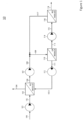
- FIG. 1 An example purification system 10 according to an embodiment of the invention is illustrated in the block diagram of Figure 1 .
- the system 10 may be capable of treating feed solutions 100 in excess of 80,000 ppm concentration by regenerating a draw solution 105 at a concentration higher than the feed 100. While a hydrostatic pressure exceeding 1200 psi may be required in some examples to re-concentrate this draw solution with an array of RO membranes in one stage, by breaking up the re-concentration into two or inure stages, each stage may operate at a hydrostatic pressure below the burst pressure of the membrane.
- High pressure RO elements are generally rated 1800 psi, but may be run up to 3000 psi when fouling and scaling may be mitigated.
- Separating the re-concentration into multiple stages may in some examples use an intermediate pressure driven, salt rejecting membrane or membranes. While the difference in hydrostatic pressure or osmotic pressure across these membranes may not be increased with respect to the limits of a conventional RO membrane, the feed osmotic pressure may be increased by also increasing the permeate osmotic pressure. which may keep the difference in osmotic pressure between the two steams constant.
- a membrane with a reduced salt rejection with respect to conventional RO membranes, such as an NR membrane or loosened RO membrane, may be used.
- the system 10 illustrates a two-stage FO/RO system which may be capable of treating high concentration feeds to concentrations less than 120 kppm.
- the system may use a sodium chloride draw solute, but may be utilized with other draw solutes, in single form or in combination.
- the system includes three membrane arrays; an FO module 103, a low rejection pressure driven salt rejecting module 110 (LR), and an RO module 116.
- the FO module 103 generally includes an array of FO membranes, arranged in parallel, series, or a combination of both. Any suitable FO membrane may generally be used.
- the FO module 103 may generally have a high salt rejection (e.g. typically greater than 95%).
- the LR module 110 generally includes an array of membranes having a salt rejection less than RO (which is, for example, typically 99% or greater).
- the array of membranes in the LR module may be arranged in series, parallel, or a combination thereof.
- the module may have salt rejection (e.g. sodium chloride rejection) of less than 90%, less than 80% in some examples, less than 70% in some examples, less than 60% in some examples, less than 50% in some examples.
- the RO module 116 generally includes an array of RO membranes, arranged in parallel, series, or a combination of both. Any suitable RO membrane may generally be used.
- the RO module may have high rejection (e.g. typically greater than 99%).
- a high concentration feed stream 102 enters the FO module 103, where it is dewatered and leaves the system as reject stream 104.
- any stream may be used as the feed stream, including but not limited to, seawater or wastewater.
- a high concentration draw stream 105 e.g., 120 kppm
- flows e.g., I MGD
- a pressure which may be near atmospheric enters the FO module 103, absorbing mass and becoming diluted, exiting as a first stream 106 of a reduced concentration (e.g., 80 kppm) and flows (e.g., 1.5 MGD) with a pressure which may be near atmospheric.
- This stream may be too high in concentration to recover with a single stage RO.
- the stream may then be pressurized (e.g., 1000 psi) by a pump 107. which may be a high pressure pump, then combined with an adjacent reverse osmosis reject (e.g. brine) stream 117 (which may be a high pressure stream) with a flow rate (e.g., 0.5 MGD), forming stream 109 with a flow rate (e.g., 2 MGD).
- the pressure may remain elevated (e.g., 1000 psi).
- the stream 109 may be contacted with a low rejection pressure driven salt rejecting module 110 (LR), which may have a rejection of, e,g, 50% and a recovery rate of 50%.
- the salt rejection e.g.
- sodium chloride rejection of the module 110 may be less than 40%, less than 50%, less than 60%, less than 70%, less than 80%, or less than 90% in some examples. In other examples, the recovery rate of the module 110 may be less than 90%, less than 70%, less than 50%, less than 30% and greater than 10% In contrast to RO membranes where, for example, a 50% recovery results in a reject stream that is approximately twice the concentration of the feed stream limiting the recovery at high TDS, LR membranes will have a concentration less than twice the feed stream due to bulk salt transfer across the membrane, allowing for higher recovery ratios than typical RO membranes.
- the hydrostatic pressure of stream 109 may overcome the average difference in concentration across the membrane (e.g., 40 kppm by 300 psi).
- a low concentration stream 113 e.g., 40 kppm that flows (e.g., 1 MGD), and which may have a pressure near atmospheric
- a high concentration draw stream 111 e.g.120 kppm which may flow (e.g., 1 MGD) and have a higher pressure (e.g., 1000 psi).
- the pressure of this stream may be decreased across an energy recovery device 112 (e.g. hydraulic motor), forming a low pressure high concentration draw stream 105 that may be fed to the FO membrane array 103.
- the low concentration stream 113 may then be pressurized to a higher pressure (e.g., 1000 psi) by a pump 114, forming stream 115.
- This stream is fed to die stage 2 RO module 116 which may have a high rejection (e.g. greater than 99%, greater than 98%, greater than 97%, greater than 95%. or greater than 90% in some examples).
- the hydrostatic pressure may overcome the average difference in concentration across the membrane (e.g., 40 kppm by 300 psi) and may generate a high quality product stream 118.
- the product stream 118 may have a concentration of nearly 0 kppm (e.g., 350 ppm), flow of 0.5 MGD and pressure near atmospheric
- the RO module 116 may also produce a reverse osmosis reject stream 117 which may be combined with stream 108 and recycled as discussed above.
- the reverse osmosis reject stream 117 may have a concentration of 80 kppm, flow of 0.5 MGD and pressure of 1000 psi.
- a nanofiltration (NF) membrane may be used as an intermediate stage 1 pressure driven salt rejecting membrane array, in module 110.
- the NF membrane may reject monovalent salts at a higher percentage than multivalent salts. This may be leveraged by having a draw solute that includes both monovalent salts (e.g. sodium chloride or lithium chloride) and multivalent salts (e.g. magnesium chloride, calcium chloride, magnesium sulfate, or sodium phosphate).
- monovalent salts e.g. sodium chloride or lithium chloride
- multivalent salts e.g. magnesium chloride, calcium chloride, magnesium sulfate, or sodium phosphate
- a NF membrane may reject monovalent salts at 70% and multivalent salts at 30%, although other rejection percentages may be used in other examples.
- the multivalent salt may be more likely to leave the module in the low concentration stream 113, and the monovalent in the high concentration draw stream 111.
- the stage 2 RO module 116 may be desalting stream 115 whose salts are predominately multivalent salts, which may result in a higher quality, lower TDS product stream 118.
- the NF membrane may reject multivalent salts better than monovalent salts, which may result in higher specific RO flux.
- the FO module 103 may receive a draw solution stream 105 whose salts are predominately monovalent salts, which may result in a higher specific flux than would be reached with multivalent salts.
- Table 1 contains example flow rates, hydrostatic pressures, and concentrations of solute for different points in the system illustrated in Figure 1 .
- the values given in Table 1 are exemplary and should not be interpreted to limit the embodiments of the invention to the values given.
- Other values of flow rates, hydrostatic pressures, and concentrations of solute may be used in other examples Table 1: Exemplary Values for Two Stage FO/RO System 10 Element number in Fig.
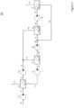
- FIG. 2 illustrates a block diagram of a three stage system 20 according to an embodiment of the invention.
- the three stage FO RO system 20 may be capable of treating high concentration feeds to concentrations less than 160 kppm.
- the system is considered with a sodium chloride draw solute, but may be utilized with other draw solutes, in single form or in combination with other solutes (e.g. mulrivalents). including sodium chloride.
- the system 20 may include four membrane arrays; an FO module 103 with high rejection (e.g. typically greater than 95%).
- a high concentration feed stream 102 may enter the FO module 103, where is it dewatered and leaves the system as reject or waste stream 104.
- a high concentration draw stream 120 (e.g. 160 kppm) flows (e.g., 1.5 MGD) with a pressure which may be near atmospheric, enters the FO module 103 absorbing mass and becoming diluted, exiting as stream 121 (e.g., 120 kppm), with increase flow (e.g., 2 MGD) with a pressure which may be near atmospheric.
- This stream may be too high in concentration to recover with a single or double stage RO.
- the stream is then pressurized to a higher pressure (e.g., 1000 psi) by a pump 122, then combined with an adjacent high pressure stream 133, forming stream 124, with an increased flow (e.g., 3 MGD) but same pressure (e.g., 1000 psi).
- the stream 124 is contacted with LR module 125 which may have a rejection of 33%.
- the hydrostatic pressure e.g. 1000 psi
- the hydrostatic pressure may overcome the average difference in concentration across the membrane of (e.g.. 60 kppm by 300 psi), generating a low concentration stream 128 (e.g., 30 kppm) with a reduced flow (e.g., 1.5 MGD), and may have a pressure near atmospheric.
- the LR module 125 may also produce a high concentration draw stream 126 (e.g., 160 kppm), with a reduced flow (e.g., 1.5 MGD), and higher pressure (e.g., 1000
- the pressure of stream 126 may be decreased across a hydraulic motor (energy recovery device) 127, forming stream 120 that may be fed to the FO membrane array 103.
- the low concentration stream 128 may then be pressurized (e.g., 1000 psi) by a second pump 129, forming stream 130.
- This stream 130 is then combined with an adjacent high pressure stream 138, forming stream 131, with an increased flow (e.g., 2 MGD).
- the stream 131 is contacted with an LR module 132 which may have a rejection of 50%.
- the hydrostatic pressure (e.g., 1000 psi) may overcome the average difference in concentration across the membrane (e.g., 60 kppm by 300 psi), generating a dilute stream 134 (e.g., 40 kppm), with reduced flow (e.g., 1 MGD), and may have a pressure near atmospheric, and a high concentration rejection stream 133 (e.g., 120 kppm), which may have reduced flow (e.g., 1 MGD) and higher pressure (e.g., 1000 psi).
- This high concentration rejection stream 133 may be combined with stream 123 as described above and recycled.
- the dilute stream 134 may then be pressurized (e.g., 1000 psi) by a third pump 135, forming stream 136.
- This stream 136 is fed to the stage 3 RO module 137, which may have a rejection greater than 99%.
- the hydrostatic pressure e.g., 1000 psi
- the RO module 137 may also produce and a reverse osmosis reject stream 138 which may have a concentration of 80 kppm, flow of 0.5 MGD and pressure of 1000 psi.
- This reverse osmosis reject stream 138 may be combined with stream 130 as described above and recycled.
- Table 2 contains example flow rates, hydrostatic pressures, and concentrations of solute for different points in the system illustrated in Figure 2 .
- the values given in Table 2 are exemplary and should not be interpreted to limit the embodiments of the invention to the values given. Other values of flow rates, hydrostatic pressures, and concentrations of solute may be possible.
- Table 2 Exemplary Values for Three Stage FO/RO System 20 Element number in Fig.
- example systems include a FO module whose draw stream output is provided to one, or a series of, LR modules having low rejection pressure driven salt rejecting membranes.
- Each LR module may produce a low concentration stream provided to a next LR module in the series, or to a later RO module, and a higher concentration stream fed back to a last stage (e.g. the FO module draw or to an earlier LR module).
- a subsequent RO module is provided which receives the low concentration stream from a last LR module in the series, providing a product stream.
- the feed and draw water of examples described herein, including in systems 10 and 20, illustrated in Figures 1 and 2 may have additional pretreatment to remove increased concentrations of sealants or foulants at high recovery Recovery is the ratio of the permeate stream (X) divided by the feed stream (Y).
- Scalants may include, but are not limited to: calcium carbonate, sodium carbonate, silica, gypsum, barium sulfate, strontium sulfate, and calcium fluoride.
- Foulants may include, but are not limited to: small organic molecules, particulates or colloids, or biological film growth.
- the feed and draw water may be treated with antiscalants or antifoulants to prevent scaling or fouling of the FO membranes or the RO membranes.
- Antiscalants may include condensed polyphosphates, organophosphonates, and polycloctrolytes. Dechlorination of the feed water may be achieved by the addition of sodium bisulfite. The pH of feed water and the draw may be raised to remove hardness and alkalinity or increase rejection of weakly ionized anions, such as borate, cyanide, fluoride, and certain arsenic and selenium compounds. The pH of feed water and the draw may be lowered to reduce scaling. Either the feed or the draw may have additional antiscalants, antifoulants, pH adjustments, degassing, in any combination and in any order, depending on the feed water, the operation parameters (e.g., recovery ratio), and the desired system permeate quality.
- the operation parameters e.g., recovery ratio
- the sealant and foulant removal process of the draw stream may be completed in batch mode where the draw loop is drained and replaced with another draw solution while the sealant and foulant removal process is completed.
- the sealant and foulant removal process may also be completed in semi-batch mode, such that a small portion of the draw loop is removed for treatment at a time.
- the rejection and the scaling and fouling propensity of the forward osmosis membrane and the reverse osmosis membrane may be independently adjusted. The system may then be optimized to minimize consumables and maximize overall efficiency as desired for a specific application.
- the draw solution composition of the FO/RO systems shown in Figures 1 and 2 may be tuned to optimize the performance of the system.
- the draw solution may be any aqueous solution with high rejection from a reverse osmosis membrane.
- the draw solute may preferably be an inorganic salt such as sodium chloride, magnesium chloride, magnesium sulfate, sodium sulfate, of sodium phosphate.
- the draw solute may be monovalent or muhivalent.
- the draw solution may be a mixture of salts, both monovalent or multivalent.
- the low rejection reverse osmosis membrane such as those included in the LR modules, may be a standard reverse osmosis membrane for high sodium chloride rejection (e.g.
- the low rejection reverse osmosis membrane maybe a nanoliltration membrane, such as DOW NF90. with moderate sodium chloride rejection (greater than 80%) and high multivalent rejection (e.g. greater than 90%).
- the low rejection reverse osmosis membrane maybe a sulfonated polysulfone nanofiltration membrane, such as Hydranautics HydraCoRe70.
- the low rejection reverse osmosis membrane which may be included in the LR modules, may be tuned by chemically treating a standard reverse osmosis membrane.
- the low rejection reverse osmosis membrane may be a thin film composite membrane with a polyamide selective layer.
- the crosslinking density of the polyamide layer may be reduced, increasing salt passage (reducing selectivity) and increasing water permeability.
- a DOW SW30 membrane may be exposed to 1000 ppm sodium hypochlorite solution for 10 minutes to 6 hours and then rinsed with sodium bisulfate or water.
- the sodium chloride rejection of the membrane may be reduced from 99% to 10%.
- the treated membrane may have high multivalent salt rejection.
- the draw solute composition of monovalent and multivalent salts and the reverse osmosis membrane may be chosen depending on the relative rejection of the membrane to monovalent salts and multivalent salts and the preferred operation parameters.
- a multi-port purification system 30 (which is not claimed) is illustrated in Figure 3 .
- a draw solution 300 is brought to a first port 310 of a first RO element 315 by pump 305.
- a reject stream 355 from the first RO element 315 is depressurized and returned by energy recovery device 370 to the draw solution as a concentrated stream 360.
- the permeate 320 is pressurized by pump 325 and delivered to an input port 330 in a second RO element 335.
- Product leaves the RO element 335 as stream 340.
- a reject stream 345 is depressurized by an energy recovery device 365 and returned to a second port 350 in the first RO element 315.
- osmotic pre-treatment may be used with multiple RO stages and a 4-port RO element.
- the 4-port RO element may allow a saline solution to circulate through the permeate channel of RO1, which may decrease the effective osmotic pressure differential across the membrane RO1,
- Vessel RO2 may utilize a standard 3-port RO element.
- the concentration of the intermediate draw solution may be between the inlet draw solution concentration and the product water. In a two stage system, this concentration may be about half of the difference between the inlet draw solution and product water concentrations.
- the salinity difference across each RO element may be only about half of the total reduction in salinity from inlet to product.
- the water recovery of this multi-stage RO system alone without FO pre-treatment is the product of water recoveries of each of the RO steps.
- the overall system water recovery is only 1 %.
- the overall recovery of the whole system is equal to the water recovery of the FO loop and independent of the water-recovery of the RO portion of the system, thus it can be greater than 1%.
Landscapes
- Engineering & Computer Science (AREA)
- Chemical & Material Sciences (AREA)
- Water Supply & Treatment (AREA)
- Chemical Kinetics & Catalysis (AREA)
- Nanotechnology (AREA)
- Life Sciences & Earth Sciences (AREA)
- Hydrology & Water Resources (AREA)
- Environmental & Geological Engineering (AREA)
- Organic Chemistry (AREA)
- Separation Using Semi-Permeable Membranes (AREA)
Description
- This application claims the benefit of the earlier filing date of
U.S. Provisional Application No. 61/794,537 filed March 15, 2013 - Examples described herein relate to separation systems, elements, and methods which may be used for forward osmosis (FO) or reverse osmosis (RO), or generally any separation process.
- This invention was made with Government support under contract number W911NH.09-C-00T9 awarded by the Department of Defense. The Government has certain rights in this invention.
- For osmotic pre-treatment, higher draw solution osmotic potential substantially increases the system's operating window of feed concentration. Conventional systems typically have a limit on draw solution concentration for reverse osmosis (RO).
- In RO systems, the maximum feed salinity treatable is limited by the maximum salinity of the draw solution. The draw solution is typically limited to a high point of 80.000 ppm, as any greater concentration would require a RO hydrostatic pressure that would rupture the membrane. Maximum RO operation hydrostatic pressure is typically between 1000 and 1200 psi. The following generally explains this limitation. The flux across the RO membrane is proportional to the active membrane pressure. The active membrane pressure is the difference in hydrostatic pressure across the RO membrane (typically 800 psi feed to near atmosphere permeate) less the difference in osmotic pressure across the RO membrane (typically 300 psi feed to near 0 psi permeate). The active membrane pressure may be adjusted by changing any of the aforementioned values. While the osmotic pressure of the feed is easily adjustable in the system, the osmotic pressure of the permeate is typically fixed near zero, and is a function of the rejection of the RO membrane (defined as one minus the fraction of salt that passes into the permeate, typical RO rejections are greater than 99%).
- Consequently, purification systems that are capable of treating feed solutions in excess concentrations of 80,000 ppm typically use heat and phase change, resulting in large foot prints, high energy demands and high capital system costs compared to membrane driven systems. These systems are used when the feed total disolved solute (TDS) is greater than 80,000 ppm, or when lower TDS feed solutions must be treated to high recoveries with rejects exceeding 80,000 ppm (e.g., zero liquid discharge applications).
-
WO 2010/067065 A1 relates to a process for removing a solvent, such as water, from a source solution. -
US 2010/018921 A1 relates to maintenance and operation methods to clean and operate reverse osmosis filtration systems. - Examples of apparatuses, systems, and methods for purification are disclosed herein.
- According to an aspect of the present disclosure, there is provided an apparatus, comprising: a forward osmosis module configured to receive a feed stream and a high concentration draw stream, wherein the forward osmosis module is further configured to produce a first stream comprising water from the feed stream and the high concentration draw stream; a pump configured to pressurize the first stream; a low rejection membrane module having a salt rejection of less than 90% configured to receive the pressurized first stream and to produce the high concentration draw stream and a low concentration stream; and a reverse osmosis module configured to receive the low concentration stream and to produce a product stream and a reverse osmosis reject stream, wherein the reverse osmosis module has a higher salt rejection than the low rejection membrane module, wherein the reverse osmosis reject stream is combined with the pressurized first stream provided to the low rejection module to form a stream prior to entering the low rejection membrane module, wherein the stream is recycled to form a portion of the high concentration draw stream.
- The draw stream may include a multivalent salt.
- The apparatus may further comprise a second pump configured to pressurize the low concentration stream provided to the reverse osmosis module.
- The apparatus may further comprise an energy recovery device configured to reduce the pressure of the high concentration draw stream produced by the low rejection module.
- The low rejection module may comprises a membrane with a salt rejection less than 90%.
- The apparatus may further comprise a dosing pump configured to provide a solute to the high concentration draw stream.
- According to another aspect of the present disclosure, there is provided a method, comprising: providing a draw stream to a forward osmosis module; providing a feed stream to the forward osmosis module; filtering the feed stream with the forward osmosis module to produce a first stream; pressurizing the first stream; filtering the pressurized first stream with a low rejection module having a salt rejection of less than 90% to produce a dilute stream and the draw stream; filtering the dilute stream with a reverse osmosis module to produce a product stream, and producing a reject stream with the reverse osmosis module, wherein the reverse osmosis module has a higher salt rejection than the low rejection membrane module; recycling the reject stream to form a portion of the draw stream via the low rejection module; and combining the reject stream and the pressurized first stream to form a stream prior to entering the low rejection module.
- The method may further include adding anti-sealants or anti-foulants to the feed stream.
- The method may further comprise directing the draw stream through an energy recovery device to lower a pressure of the draw stream; and directing the draw stream through the forward osmosis module.
- The method may further comprise filtering the dilute stream with a second low rejection module having a salt rejection of less than 90% to produce a low concentration stream; and providing the low concentration stream to the reverse osmosis module.
-
-
Figure 1 is a block diagram of a purification system according to an embodiment of the invention. -
Figure 2 is a block diagram of a purification system according to another embodiment of the invention. -
Figure 3 is a block diagram of a purification system (which is not claimed). - Certain details are set forth below to provide a sufficient understanding of embodiments of the invention. However, it will be clear to one skilled in the art that embodiments of the invention may be practiced without various of these particular details. In some instances, well-known chemical structures, chemical components, molecules, materials, manufacturing components, control systems, electronic components, timing protocols, and software operations have not been shown in detail in order to avoid unnecessarily obscuring the described embodiments of the invention.
- In examples described herein, existing limits on draw solution concentration for reverse osmosis (RO) and high pressure RO may be overcome using nanofiltration (NF) and/or RO membrane modules staged in an array of two or more modules deep, and allowing increased salt concentrations on the permeate side of the NF or RO membrane in upstream stages. In this way, the effective concentration differential across each RO membrane is reduced along with the required applied hydraulic pressure. The increased salt concentration on the permeate side of the RO membrane can be produced in several ways, including utilizing less selective RO membranes or a style of RO membrane with 4 ports (e.g., draw in/out, permeate in/out). This staging of RO modules is typically not done because of the multiplicative nature of recoveries. meaning that total system recovery may be very low. Advantages of examples described herein and any described disadvantages of conventional systems are not intended to be limiting, and are provided to aid in understanding. It should be understood that some examples may not exhibit all, or even any, of the described advantages. Moreover, some examples may not address all, or even any, of the described disadvantages of conventional systems.
- By pairing multiple reverse osmosis (RO) vessels with a forward osmosis pre-treatment, the overall system recovery in some examples may be decoupled from the RO system recovery. Coupling of forward osmosis (FO) pre-treatment with multi-stage NF and/or RO allows for increase of overall system water recovery in some examples compared to what the recovery would be if FO pre-treatment system was not used.
- An
example purification system 10 according to an embodiment of the invention is illustrated in the block diagram ofFigure 1 . Thesystem 10 may be capable of treatingfeed solutions 100 in excess of 80,000 ppm concentration by regenerating adraw solution 105 at a concentration higher than thefeed 100. While a hydrostatic pressure exceeding 1200 psi may be required in some examples to re-concentrate this draw solution with an array of RO membranes in one stage, by breaking up the re-concentration into two or inure stages, each stage may operate at a hydrostatic pressure below the burst pressure of the membrane. High pressure RO elements are generally rated 1800 psi, but may be run up to 3000 psi when fouling and scaling may be mitigated. - Separating the re-concentration into multiple stages may in some examples use an intermediate pressure driven, salt rejecting membrane or membranes. While the difference in hydrostatic pressure or osmotic pressure across these membranes may not be increased with respect to the limits of a conventional RO membrane, the feed osmotic pressure may be increased by also increasing the permeate osmotic pressure. which may keep the difference in osmotic pressure between the two steams constant. A membrane with a reduced salt rejection with respect to conventional RO membranes, such as an NR membrane or loosened RO membrane, may be used.
- Returning to
Figure 1 , thesystem 10 illustrates a two-stage FO/RO system which may be capable of treating high concentration feeds to concentrations less than 120 kppm. The system may use a sodium chloride draw solute, but may be utilized with other draw solutes, in single form or in combination. The system includes three membrane arrays; anFO module 103, a low rejection pressure driven salt rejecting module 110 (LR), and anRO module 116. TheFO module 103 generally includes an array of FO membranes, arranged in parallel, series, or a combination of both. Any suitable FO membrane may generally be used. TheFO module 103 may generally have a high salt rejection (e.g. typically greater than 95%). TheLR module 110 generally includes an array of membranes having a salt rejection less than RO (which is, for example, typically 99% or greater). The array of membranes in the LR module may be arranged in series, parallel, or a combination thereof. Generally, the module may have salt rejection (e.g. sodium chloride rejection) of less than 90%, less than 80% in some examples, less than 70% in some examples, less than 60% in some examples, less than 50% in some examples. TheRO module 116 generally includes an array of RO membranes, arranged in parallel, series, or a combination of both. Any suitable RO membrane may generally be used. The RO module may have high rejection (e.g. typically greater than 99%). - During example operation, a high
concentration feed stream 102, enters theFO module 103, where it is dewatered and leaves the system asreject stream 104. Generally, any stream may be used as the feed stream, including but not limited to, seawater or wastewater. A high concentration draw stream 105 (e.g., 120 kppm) flows (e.g., I MGD) with a pressure which may be near atmospheric enters theFO module 103, absorbing mass and becoming diluted, exiting as afirst stream 106 of a reduced concentration (e.g., 80 kppm) and flows (e.g., 1.5 MGD) with a pressure which may be near atmospheric. This stream may be too high in concentration to recover with a single stage RO. The stream may then be pressurized (e.g., 1000 psi) by apump 107. which may be a high pressure pump, then combined with an adjacent reverse osmosis reject (e.g. brine) stream 117 (which may be a high pressure stream) with a flow rate (e.g., 0.5 MGD), formingstream 109 with a flow rate (e.g., 2 MGD). The pressure may remain elevated (e.g., 1000 psi). Thestream 109 may be contacted with a low rejection pressure driven salt rejecting module 110 (LR), which may have a rejection of, e,g, 50% and a recovery rate of 50%. In other examples, the salt rejection (e.g. sodium chloride rejection) of themodule 110 may be less than 40%, less than 50%, less than 60%, less than 70%, less than 80%, or less than 90% in some examples. In other examples, the recovery rate of themodule 110 may be less than 90%, less than 70%, less than 50%, less than 30% and greater than 10% In contrast to RO membranes where, for example, a 50% recovery results in a reject stream that is approximately twice the concentration of the feed stream limiting the recovery at high TDS, LR membranes will have a concentration less than twice the feed stream due to bulk salt transfer across the membrane, allowing for higher recovery ratios than typical RO membranes. The hydrostatic pressure ofstream 109 may overcome the average difference in concentration across the membrane (e.g., 40 kppm by 300 psi). generating a low concentration stream 113 (e.g., 40 kppm) that flows (e.g., 1 MGD), and which may have a pressure near atmospheric, and a high concentration draw stream 111 (e.g.120 kppm) which may flow (e.g., 1 MGD) and have a higher pressure (e.g., 1000 psi). - The pressure of this stream may be decreased across an energy recovery device 112 (e.g. hydraulic motor), forming a low pressure high
concentration draw stream 105 that may be fed to theFO membrane array 103. Thelow concentration stream 113 may then be pressurized to a higher pressure (e.g., 1000 psi) by apump 114, formingstream 115. This stream is fed to die stage 2RO module 116 which may have a high rejection (e.g. greater than 99%, greater than 98%, greater than 97%, greater than 95%. or greater than 90% in some examples). The hydrostatic pressure may overcome the average difference in concentration across the membrane (e.g., 40 kppm by 300 psi) and may generate a highquality product stream 118. - The
product stream 118 may have a concentration of nearly 0 kppm (e.g., 350 ppm), flow of 0.5 MGD and pressure near atmospheric TheRO module 116 may also produce a reverseosmosis reject stream 117 which may be combined withstream 108 and recycled as discussed above. The reverseosmosis reject stream 117 may have a concentration of 80 kppm, flow of 0.5 MGD and pressure of 1000 psi. - A nanofiltration (NF) membrane may be used as an
intermediate stage 1 pressure driven salt rejecting membrane array, inmodule 110. Unlike RO membranes which tend to reject multivalent salts at a high percentage than monovalent salts, the NF membrane may reject monovalent salts at a higher percentage than multivalent salts. This may be leveraged by having a draw solute that includes both monovalent salts (e.g. sodium chloride or lithium chloride) and multivalent salts (e.g. magnesium chloride, calcium chloride, magnesium sulfate, or sodium phosphate). For example, a NF membrane may reject monovalent salts at 70% and multivalent salts at 30%, although other rejection percentages may be used in other examples. When entering themodule 110, the multivalent salt may be more likely to leave the module in thelow concentration stream 113, and the monovalent in the highconcentration draw stream 111. - Consequently, the stage 2
RO module 116 may be desaltingstream 115 whose salts are predominately multivalent salts, which may result in a higher quality, lowerTDS product stream 118. In another example, the NF membrane may reject multivalent salts better than monovalent salts, which may result in higher specific RO flux. In other examples, theFO module 103 may receive adraw solution stream 105 whose salts are predominately monovalent salts, which may result in a higher specific flux than would be reached with multivalent salts. - Table 1 contains example flow rates, hydrostatic pressures, and concentrations of solute for different points in the system illustrated in
Figure 1 . The values given in Table 1 are exemplary and should not be interpreted to limit the embodiments of the invention to the values given. Other values of flow rates, hydrostatic pressures, and concentrations of solute may be used in other examplesTable 1: Exemplary Values for Two Stage FO/ RO System 10Element number in Fig. 1 Flow (MGD) Hydrostatic pressure (psi) Concentration (ppm) Feed 102 0.63 5.0 35,000 Feed Reject 104 0.13 0.0 105,000 FO draw reject 106 1.50 0.5 80,000 Pressurized FO draw reject 108 1.50 980 80,000 Stage 1 LR draw feed109 2.00 980 80,000 Stage 1 LR draw reject111 1.00 965 120,000 FO draw feed 105 1.00 3.0 120,000 Stage 1 LR permeate113 1.00 0.5 40,000 Stage 2 RO feed 115 1.00 1000 40,000 Stage 2 RO reject 117 0.50 985 80,000 System permeate 118 0.50 0.0 350 -
Figure 2 illustrates a block diagram of a threestage system 20 according to an embodiment of the invention. The three stageFO RO system 20 may be capable of treating high concentration feeds to concentrations less than 160 kppm. The system is considered with a sodium chloride draw solute, but may be utilized with other draw solutes, in single form or in combination with other solutes (e.g. mulrivalents). including sodium chloride. Thesystem 20 may include four membrane arrays; anFO module 103 with high rejection (e.g. typically greater than 95%). an intermediate stage pressure driven salt rejecting membrane array (e.g. LR module) 125 with rejection less than RO (e.g. typically 33%), an intermediate stage 2 pressure driven salt rejecting membrane array (e.g. LR module) 132 with rejection less than RO (e.g. typically 50%) and final stage 3 RO module 137 with high rejection (e.g. typically greater than 99%). - During operation, a high
concentration feed stream 102, may enter theFO module 103, where is it dewatered and leaves the system as reject orwaste stream 104. A high concentration draw stream 120 (e.g. 160 kppm) flows (e.g., 1.5 MGD) with a pressure which may be near atmospheric, enters theFO module 103 absorbing mass and becoming diluted, exiting as stream 121 (e.g., 120 kppm), with increase flow (e.g., 2 MGD) with a pressure which may be near atmospheric. This stream may be too high in concentration to recover with a single or double stage RO. The stream is then pressurized to a higher pressure (e.g., 1000 psi) by apump 122, then combined with an adjacenthigh pressure stream 133, formingstream 124, with an increased flow (e.g., 3 MGD) but same pressure (e.g., 1000 psi). Thestream 124 is contacted withLR module 125 which may have a rejection of 33%. The hydrostatic pressure (e.g. 1000 psi) may overcome the average difference in concentration across the membrane of (e.g.. 60 kppm by 300 psi), generating a low concentration stream 128 (e.g., 30 kppm) with a reduced flow (e.g., 1.5 MGD), and may have a pressure near atmospheric. TheLR module 125 may also produce a high concentration draw stream 126 (e.g., 160 kppm), with a reduced flow (e.g., 1.5 MGD), and higher pressure (e.g., 1000 psi). - The pressure of stream 126 may be decreased across a hydraulic motor (energy recovery device) 127, forming
stream 120 that may be fed to theFO membrane array 103. Thelow concentration stream 128 may then be pressurized (e.g., 1000 psi) by asecond pump 129, formingstream 130. Thisstream 130 is then combined with an adjacent high pressure stream 138, formingstream 131, with an increased flow (e.g., 2 MGD). Thestream 131 is contacted with anLR module 132 which may have a rejection of 50%. The hydrostatic pressure (e.g., 1000 psi) may overcome the average difference in concentration across the membrane (e.g., 60 kppm by 300 psi), generating a dilute stream 134 (e.g., 40 kppm), with reduced flow (e.g., 1 MGD), and may have a pressure near atmospheric, and a high concentration rejection stream 133 (e.g., 120 kppm), which may have reduced flow (e.g., 1 MGD) and higher pressure (e.g., 1000 psi). This highconcentration rejection stream 133 may be combined withstream 123 as described above and recycled. Thedilute stream 134 may then be pressurized (e.g., 1000 psi) by a third pump 135, formingstream 136. Thisstream 136 is fed to the stage 3 RO module 137, which may have a rejection greater than 99%. The hydrostatic pressure (e.g., 1000 psi) may overcome the average difference in concentration across the membrane (e.g., 60 kppm by 300 psi), generating a highquality product stream 118 which may have a concentration of nearly 0 kppm, flow of 0.5 MGD and pressure near atmospheric. The RO module 137 may also produce and a reverse osmosis reject stream 138 which may have a concentration of 80 kppm, flow of 0.5 MGD and pressure of 1000 psi. This reverse osmosis reject stream 138 may be combined withstream 130 as described above and recycled. - Table 2 contains example flow rates, hydrostatic pressures, and concentrations of solute for different points in the system illustrated in
Figure 2 . The values given in Table 2 are exemplary and should not be interpreted to limit the embodiments of the invention to the values given. Other values of flow rates, hydrostatic pressures, and concentrations of solute may be possible.Table 2: Exemplary Values for Three Stage FO/ RO System 20Element number in Fig. 2 Flow (MGD) Hydrostatic pressure (psi) Concentration (ppm) Feed 102 1.0 5.0 80,000 Feed Reject 104 0.55 0.0 145,000 FO draw reject 121 2.0 0.5 120,000 Pressurized FO draw reject 123 2.0 960 120,000 Stage 1 LR draw feed124 3.0 960 120,000 Stage 1 LR draw reject126 1.5 945 160,000 FO draw feed 120 1.5 3.0 160,000 Stage 1 LR permeate128 1.5 0.5 80,000 Pressurized stage 1 LR permeate130 1.5 980 80,000 Stage 2 LR draw feed 131 2.0 980 80,000 Stage 2 LR draw reject 133 1.0 965 120,000 Stage 2 LR permeate 134 1.0 0.5 40,000 Stage 3 RO feed 136 1.0 1000 40,000 Stage 3 RO reject 138 0.5 985 80,000 System permeate 118 0.5 0.0 350 - While a two-stage system and a three-stage system have been shown in
Figures 1 and2 , respectively, any number of stages may be used in other examples. Generally, example systems include a FO module whose draw stream output is provided to one, or a series of, LR modules having low rejection pressure driven salt rejecting membranes. Each LR module may produce a low concentration stream provided to a next LR module in the series, or to a later RO module, and a higher concentration stream fed back to a last stage (e.g. the FO module draw or to an earlier LR module). A subsequent RO module is provided which receives the low concentration stream from a last LR module in the series, providing a product stream. - The feed and draw water of examples described herein, including in
systems Figures 1 and2 , may have additional pretreatment to remove increased concentrations of sealants or foulants at high recovery Recovery is the ratio of the permeate stream (X) divided by the feed stream (Y). Scalants may include, but are not limited to: calcium carbonate, sodium carbonate, silica, gypsum, barium sulfate, strontium sulfate, and calcium fluoride. Foulants may include, but are not limited to: small organic molecules, particulates or colloids, or biological film growth. The feed and draw water may be treated with antiscalants or antifoulants to prevent scaling or fouling of the FO membranes or the RO membranes. Antiscalants may include condensed polyphosphates, organophosphonates, and polycloctrolytes. Dechlorination of the feed water may be achieved by the addition of sodium bisulfite. The pH of feed water and the draw may be raised to remove hardness and alkalinity or increase rejection of weakly ionized anions, such as borate, cyanide, fluoride, and certain arsenic and selenium compounds. The pH of feed water and the draw may be lowered to reduce scaling. Either the feed or the draw may have additional antiscalants, antifoulants, pH adjustments, degassing, in any combination and in any order, depending on the feed water, the operation parameters (e.g., recovery ratio), and the desired system permeate quality. - The sealant and foulant removal process of the draw stream, such as pH adjustments, may be completed in batch mode where the draw loop is drained and replaced with another draw solution while the sealant and foulant removal process is completed. The sealant and foulant removal process may also be completed in semi-batch mode, such that a small portion of the draw loop is removed for treatment at a time. The rejection and the scaling and fouling propensity of the forward osmosis membrane and the reverse osmosis membrane may be independently adjusted. The system may then be optimized to minimize consumables and maximize overall efficiency as desired for a specific application.
- Unlike traditional reverse osmosis systems, the draw solution composition of the FO/RO systems shown in
Figures 1 and2 may be tuned to optimize the performance of the system. The draw solution may be any aqueous solution with high rejection from a reverse osmosis membrane. The draw solute may preferably be an inorganic salt such as sodium chloride, magnesium chloride, magnesium sulfate, sodium sulfate, of sodium phosphate. The draw solute may be monovalent or muhivalent. The draw solution may be a mixture of salts, both monovalent or multivalent. The low rejection reverse osmosis membrane, such as those included in the LR modules, may be a standard reverse osmosis membrane for high sodium chloride rejection (e.g. greater than 99%), such as DOW SW30 membrane. The low rejection reverse osmosis membrane maybe a nanoliltration membrane, such as DOW NF90. with moderate sodium chloride rejection (greater than 80%) and high multivalent rejection (e.g. greater than 90%). The low rejection reverse osmosis membrane maybe a sulfonated polysulfone nanofiltration membrane, such as Hydranautics HydraCoRe70. - In both systems illustrated in
Figures 1 and2 , the low rejection reverse osmosis membrane, which may be included in the LR modules, may be tuned by chemically treating a standard reverse osmosis membrane. In some examples, the low rejection reverse osmosis membrane may be a thin film composite membrane with a polyamide selective layer. The crosslinking density of the polyamide layer may be reduced, increasing salt passage (reducing selectivity) and increasing water permeability. For example, a DOW SW30 membrane may be exposed to 1000 ppm sodium hypochlorite solution for 10 minutes to 6 hours and then rinsed with sodium bisulfate or water. The sodium chloride rejection of the membrane may be reduced from 99% to 10%. The treated membrane may have high multivalent salt rejection. The draw solute composition of monovalent and multivalent salts and the reverse osmosis membrane may be chosen depending on the relative rejection of the membrane to monovalent salts and multivalent salts and the preferred operation parameters. - A multi-port purification system 30 (which is not claimed) is illustrated in
Figure 3 . in this example, adraw solution 300 is brought to afirst port 310 of afirst RO element 315 bypump 305. Areject stream 355 from thefirst RO element 315 is depressurized and returned byenergy recovery device 370 to the draw solution as aconcentrated stream 360. Thepermeate 320 is pressurized bypump 325 and delivered to aninput port 330 in asecond RO element 335. Product leaves theRO element 335 asstream 340. Areject stream 345 is depressurized by anenergy recovery device 365 and returned to asecond port 350 in thefirst RO element 315. - in the example shown in
Figure 3 , osmotic pre-treatment may be used with multiple RO stages and a 4-port RO element. The 4-port RO element may allow a saline solution to circulate through the permeate channel of RO1, which may decrease the effective osmotic pressure differential across the membrane RO1, Vessel RO2 may utilize a standard 3-port RO element. The concentration of the intermediate draw solution may be between the inlet draw solution concentration and the product water. In a two stage system, this concentration may be about half of the difference between the inlet draw solution and product water concentrations. In this example, the salinity difference across each RO element may be only about half of the total reduction in salinity from inlet to product. - The water recovery of this multi-stage RO system alone without FO pre-treatment is the product of water recoveries of each of the RO steps. For a system where water recovery of each of the RO steps is 10%, the overall system water recovery is only 1 %. However, when an FO pre-treatment system is coupled to a multi-stage RO system, the overall recovery of the whole system is equal to the water recovery of the FO loop and independent of the water-recovery of the RO portion of the system, thus it can be greater than 1%.
- From the foregoing it will be appreciated that, although specific embodiments of the invention have been described herein for purposes of illustration, various modifications may be made without deviating from the scope of the invention.
Claims (8)
- An apparatus, comprising:a forward osmosis module (103) configured to receive a feed stream (102) and a high concentration draw stream (105), wherein the forward osmosis module (103) is further configured to produce a first stream (106) comprising water from the feed stream (102) and the high concentration draw stream (105);a pump (107) configured to pressurize the first stream (106);a low rejection membrane module (110) having a salt rejection of less than 90% configured to receive the pressurized first stream (108) and to produce the high concentration draw stream (105) and a low concentration stream (113); anda reverse osmosis module (116) configured to receive the low concentration stream (113) and to produce a product stream (118) and a reverse osmosis reject stream (117), wherein the reverse osmosis module (116) has a higher salt rejection than the low rejection membrane module (110), wherein the reverse osmosis reject stream (117) is combined with the pressurized first stream (108) provided to the low rejection module (110) to form a stream (109) prior to entering the low rejection membrane module (110), wherein the stream (109) is recycled to form a portion of the high concentration draw stream (105).
- The apparatus of claim 1, further comprising a second pump (114) configured to pressurize the low concentration stream (113) provided to the reverse osmosis module (116).
- The apparatus of claim 1, further comprising an energy recovery device (112) configured to reduce the pressure of the high concentration draw stream (115) produced by the low rejection module (110).
- The apparatus of claim 1, further comprising a dosing pump configured to provide a' solute to the high concentration draw stream.
- A method, comprising:providing a draw stream (105, 111) to a forward osmosis module (103);providing a feed stream (102) to the forward osmosis module;filtering the feed stream (102) with the forward osmosis module (103) to produce a first stream (106);pressurizing the first stream (106);filtering the pressurized first stream (108) with a low rejection module (110) having a salt rejection of less than 90% to produce a dilute stream (113) and the draw stream (105, 111);filtering the dilute stream (113) with a reverse osmosis module (116) to produce a product stream (118), and producing a reject stream (117) with the reverse osmosis module (116), wherein the reverse osmosis module (116) has a higher salt rejection than the low rejection membrane module (110);recycling the reject stream (117) to form a portion of the draw stream (105, 111) via the low rejection module (110); andcombining the reject stream (117) and the pressurized first stream (108) to form a stream (109) prior to entering the low rejection module (110).
- The method of claim 5, further comprising:
directing the draw stream (111) through an energy recovery device (112) to lower a pressure of the draw stream (111); and directing the draw stream (111) through the forward osmosis module (103). - The method of claim 5, further comprising:
filtering the dilute stream (113) with a second low rejection module (132) having a salt rejection of less than 90% to produce a low concentration stream (134); and providing the low concentration stream (134) to the reverse osmosis module (137). - The method of claim 5, further comprising adding anti-sealants to the feed stream (102).
Applications Claiming Priority (2)
| Application Number | Priority Date | Filing Date | Title |
|---|---|---|---|
| US201361794537P | 2013-03-15 | 2013-03-15 | |
| PCT/US2014/029332 WO2014144778A1 (en) | 2013-03-15 | 2014-03-14 | Advancements in osmotically driven membrane systems including multi-stage purification |
Publications (4)
| Publication Number | Publication Date |
|---|---|
| EP2969145A1 EP2969145A1 (en) | 2016-01-20 |
| EP2969145A4 EP2969145A4 (en) | 2017-01-25 |
| EP2969145C0 EP2969145C0 (en) | 2024-08-07 |
| EP2969145B1 true EP2969145B1 (en) | 2024-08-07 |
Family
ID=51537764
Family Applications (1)
| Application Number | Title | Priority Date | Filing Date |
|---|---|---|---|
| EP14764413.2A Active EP2969145B1 (en) | 2013-03-15 | 2014-03-14 | Advancements in osmotically driven membrane systems including multi-stage purification |
Country Status (5)
| Country | Link |
|---|---|
| US (3) | US10500544B2 (en) |
| EP (1) | EP2969145B1 (en) |
| CN (2) | CN105142762B (en) |
| AU (1) | AU2014228787B2 (en) |
| WO (2) | WO2014144704A1 (en) |
Families Citing this family (47)
| Publication number | Priority date | Publication date | Assignee | Title |
|---|---|---|---|---|
| EP2934727B1 (en) | 2012-12-21 | 2024-05-01 | Porifera, Inc. | Separation systems utilizing stacked membranes and spacers |
| PE20151277A1 (en) | 2013-02-08 | 2015-09-23 | Oasys Water Inc | OSMOTIC SEPARATION METHODS AND SYSTEMS |
| CN105142762B (en) | 2013-03-15 | 2019-05-31 | 波里费拉公司 | Improvement of an osmotically driven membrane system incorporating multi-stage purification |
| CN105683093B (en) | 2013-08-05 | 2019-07-09 | 格雷迪安特公司 | Water treatment system and correlation technique |
| CN105683095B (en) | 2013-09-23 | 2019-09-17 | 格雷迪安特公司 | Desalination systems and related methods |
| WO2016057764A1 (en) * | 2014-10-10 | 2016-04-14 | Oasys Water, Inc. | Osmotic separation systems and methods |
| US10384169B2 (en) | 2014-10-31 | 2019-08-20 | Porifera, Inc. | Supported carbon nanotube membranes and their preparation methods |
| GB201501684D0 (en) * | 2015-02-02 | 2015-03-18 | Surrey Aquatechnology Ltd | Brine Concentration |
| US10167218B2 (en) | 2015-02-11 | 2019-01-01 | Gradiant Corporation | Production of ultra-high-density brines |
| US10308526B2 (en) | 2015-02-11 | 2019-06-04 | Gradiant Corporation | Methods and systems for producing treated brines for desalination |
| GB201503728D0 (en) * | 2015-03-05 | 2015-04-22 | Surrey Aquatechnology Ltd | Purification of highly saline feeds |
| KR102531484B1 (en) * | 2015-06-24 | 2023-05-10 | 포리페라 인코포레이티드 | Dehydration method and related system of alcoholic solution through forward osmosis |
| CN108367244B (en) | 2015-07-29 | 2022-05-03 | 格雷迪安特公司 | Osmotic desalination methods and related systems |
| WO2017030932A1 (en) | 2015-08-14 | 2017-02-23 | Gradiant Corporation | Selective retention of multivalent ions |
| WO2017030937A1 (en) | 2015-08-14 | 2017-02-23 | Gradiant Corporation | Production of multivalent ion-rich process streams using multi-stage osmotic separation |
| KR101838211B1 (en) * | 2015-10-16 | 2018-03-13 | 광주과학기술원 | Desalination apparatus for sea water using pressure-assisted forward osmosis and reverse osmosis) |
| ES2619113B1 (en) * | 2015-12-22 | 2018-05-08 | Acciona Agua, S.A. | PROCEDURE FOR CONTROL OF COMBINED SYSTEM OF DIRECT OSMOSIS AND REVERSE NANOFILTRATION OR OSMOSIS |
| CN108883344A (en) | 2016-01-22 | 2018-11-23 | 格雷迪安特公司 | Solid salt formation using high gas flow rates in humidifiers such as multi-stage bubble column humidifiers |
| WO2017147113A1 (en) | 2016-02-22 | 2017-08-31 | Gradiant Corporation | Hybrid desalination systems and associated methods |
| AU2017228930B2 (en) * | 2016-03-09 | 2023-03-16 | Enrgistream Pty Ltd | Process and system for treating waste water and generating power |
| CN105800851A (en) * | 2016-05-23 | 2016-07-27 | 海博伦(苏州)环境科技股份有限公司 | Forward osmosis drawing solution and cyclic regeneration method and application thereof |
| CN106082397B (en) * | 2016-06-12 | 2021-04-20 | 东华大学 | A system and method for synchronizing sewage regeneration and seawater desalination |
| WO2018027019A1 (en) * | 2016-08-04 | 2018-02-08 | Oasys Water, Inc. | Systems and methods for improving performance of forward osmosis systems |
| IL247687B (en) * | 2016-09-07 | 2018-06-28 | Israel Aerospace Ind Ltd | Method and system for liquid treatment |
| CN106422780B (en) * | 2016-11-02 | 2022-08-30 | 中国石油大学(华东) | Circulating type forward osmosis high-salinity organic wastewater treatment system capable of being continuously operated |
| WO2018119460A1 (en) * | 2016-12-23 | 2018-06-28 | Porifera, Inc. | Removing components of alcoholic solutions via forward osmosis and related systems |
| US11839853B2 (en) * | 2017-01-20 | 2023-12-12 | Trevi Systems, Inc. | Osmotic pressure assisted reverse osmosis membrane and module |
| WO2018148528A1 (en) | 2017-02-09 | 2018-08-16 | Bergstrom Robert A | Submerged reverse osmosis system |
| CN107311353A (en) * | 2017-08-17 | 2017-11-03 | 苏州富特尼水务工程有限公司 | A kind of haline water zero-discharge treatment system |
| US10882765B2 (en) * | 2017-09-25 | 2021-01-05 | Fluid Equipment Development Company, Llc | Method and system for operating a high recovery separation process |
| CN107698084B (en) * | 2017-10-17 | 2021-06-04 | 广州雅津水处理设备有限公司 | Reduce filtration system of concentrated salt volume of waste water |
| US11655547B2 (en) * | 2018-04-19 | 2023-05-23 | Sanza T. Kazadi | Method for generating clean water, hydrogen, and oxygen from contaminated effluent |
| US11878270B2 (en) | 2018-07-20 | 2024-01-23 | Porifera, Inc. | Osmosis modules having recirculation loops |
| US11629072B2 (en) | 2018-08-22 | 2023-04-18 | Gradiant Corporation | Liquid solution concentration system comprising isolated subsystem and related methods |
| WO2020071177A1 (en) * | 2018-10-05 | 2020-04-09 | オルガノ株式会社 | Water treatment device, water treatment method, forward osmosis membrane treatment method, forward osmosis membrane treatment system, and water treatment system |
| CN111346512B (en) * | 2018-12-20 | 2023-03-31 | 国家能源投资集团有限责任公司 | Reverse osmosis treatment method and reverse osmosis system for salt-containing water |
| CN111994999B (en) * | 2019-05-27 | 2022-09-27 | 国家能源投资集团有限责任公司 | Forward osmosis coupling reverse osmosis concentration system and use method thereof |
| CN111233101A (en) * | 2020-02-27 | 2020-06-05 | 广东溢达纺织有限公司 | Treatment method and treatment device for printing and dyeing wastewater |
| US12637404B2 (en) | 2020-09-15 | 2026-05-26 | Porifera, Inc. | Methods and systems for concentrating acetic acid solutions with a multi-tier, ultrahigh pressure reverse osmosis |
| WO2022108891A1 (en) | 2020-11-17 | 2022-05-27 | Gradiant Corporaton | Osmotic methods and systems involving energy recovery |
| CN112456687B (en) * | 2020-12-16 | 2024-03-12 | 北京城市排水集团有限责任公司 | Method and system for reducing landfill leachate concentrated solution |
| CN112723638A (en) * | 2020-12-29 | 2021-04-30 | 东莞市格美节能设备有限公司 | High-salinity wastewater zero-discharge treatment method |
| JPWO2023276586A1 (en) * | 2021-06-29 | 2023-01-05 | ||
| US11534719B1 (en) | 2021-07-02 | 2022-12-27 | Gradiant Corporation | Membranes with controlled porosity for serial filtration |
| EP4468881A4 (en) * | 2022-01-25 | 2026-01-21 | Porifera Inc | Alcohol removal by dilution and concentration of alcoholic solutions |
| ES2992338T3 (en) * | 2022-06-08 | 2024-12-11 | Danfoss As | Reverse osmosis and pressure retarded osmosis system |
| US12551823B2 (en) * | 2023-12-04 | 2026-02-17 | Lonnie G. Johnson | Heat driven osmosis water and power generator |
Citations (2)
| Publication number | Priority date | Publication date | Assignee | Title |
|---|---|---|---|---|
| US20100018921A1 (en) * | 2007-08-20 | 2010-01-28 | Earth Renaissance Technologies, Llc | Reverse osmosis water recover method |
| WO2010067065A1 (en) * | 2008-12-08 | 2010-06-17 | Surrey Aquatechnology Limited | Improved solvent removal |
Family Cites Families (177)
| Publication number | Priority date | Publication date | Assignee | Title |
|---|---|---|---|---|
| US2116920A (en) | 1934-01-11 | 1938-05-10 | Beau May Process Corp | Concentration of liquid food material |
| US3216930A (en) | 1963-01-04 | 1965-11-09 | Dow Chemical Co | Process for liquid recovery and solution concentration |
| GB1128181A (en) | 1965-01-20 | 1968-09-25 | Goran Heden | An apparatus for dialysis, heat exchange or gas exchange |
| US3721621A (en) | 1969-12-02 | 1973-03-20 | W Hough | Forward-osmosis solvent extraction |
| FR2189091A1 (en) | 1972-06-16 | 1974-01-25 | Srti Soc Rech Tech Ind | Compact exchange device for elements - contained in one of two fluids |
| DE2851105A1 (en) | 1978-11-25 | 1980-05-29 | Knut Stache | Osmotic sea-water desalination kit for drinking water prepn. - contains vessel, e.g. bag, with semi-permeable wall enclosing conc. nutritive soln. |
| JPS5588767A (en) | 1978-12-27 | 1980-07-04 | Tokyo Eizai Lab | Composition for thermal plastic fixing bandage that can be manufactured in solventless shape and preparation of fixing bandage |
| US4900443A (en) | 1980-03-14 | 1990-02-13 | Memtec North America Corporation | Porous aramid membranes and emulsions useful for the casting thereof |
| US4428720A (en) | 1980-04-22 | 1984-01-31 | Signode Corporation | Apparatus for producing polypropylene sheet |
| US4454176A (en) | 1981-10-21 | 1984-06-12 | E. I. Du Pont De Nemours And Company | Supported reverse osmosis membranes |
| JPS5959213A (en) | 1982-09-28 | 1984-04-05 | Teijin Ltd | Porous support membrane and composite membrane using same |
| GB8303611D0 (en) | 1983-02-09 | 1983-03-16 | Ag Patents Ltd | Concentration of alcoholic beverages |
| US4618533A (en) | 1984-11-30 | 1986-10-21 | Millipore Corporation | Porous membrane having hydrophilic surface and process |
| JPS62140620A (en) | 1985-12-16 | 1987-06-24 | Toray Ind Inc | Production of thin membrane |
| US4756835A (en) | 1986-08-29 | 1988-07-12 | Advanced Polymer Technology, Inc. | Permeable membranes having high flux-density and low fouling-propensity |
| DK641887D0 (en) | 1987-12-07 | 1987-12-07 | Danske Sukkerfab | DEVICE FOR FRACTIONING A FLUID IN TWO FRACTIONS BY MEMBRANE FILTERING |
| US4959237A (en) * | 1989-06-07 | 1990-09-25 | E. I. Du Pont De Nemours And Company | Reverse osmosis concentration of juice products with improved flavor |
| US5100556A (en) | 1989-07-21 | 1992-03-31 | The Standard Oil Company | Transverse sheet membrane separation module, components thereof and related methods |
| US5192434A (en) | 1990-06-07 | 1993-03-09 | Dow Danmark A/S | Membrane filtration apparatus and method of making a membrane filtration unit |
| US5238574A (en) * | 1990-06-25 | 1993-08-24 | Kawasaki Jukogyo Kabushiki Kaisha | Method and apparatus having reverse osmosis membrane for concentrating solution |
| WO1993010889A1 (en) | 1991-11-25 | 1993-06-10 | The Dow Chemical Company | Spirally wound membrane device having three channels |
| US5281430A (en) | 1992-12-08 | 1994-01-25 | Osmotek, Inc. | Osmotic concentration apparatus and method for direct osmotic concentration of fruit juices |
| KR960014337B1 (en) | 1993-12-20 | 1996-10-15 | 제일합섬 주식회사 | Manufacturing method of composite semipermeable membrane |
| US5635071A (en) | 1995-01-20 | 1997-06-03 | Zenon Airport Enviromental, Inc. | Recovery of carboxylic acids from chemical plant effluents |
| US6683783B1 (en) | 1997-03-07 | 2004-01-27 | William Marsh Rice University | Carbon fibers formed from single-wall carbon nanotubes |
| US6413070B1 (en) | 1997-04-11 | 2002-07-02 | Cuno Incorporated | System for manufacturing reinforced three-zone microporous membrane |
| US6264044B1 (en) | 1997-04-11 | 2001-07-24 | Cuno, Inc. | Reinforced, three zone microporous membrane |
| US6536605B2 (en) | 1997-06-06 | 2003-03-25 | Koch Membrane Systems, Inc. | High performance composite membrane |
| US6132804A (en) | 1997-06-06 | 2000-10-17 | Koch Membrane Systems, Inc. | High performance composite membrane |
| US6037808A (en) | 1997-12-24 | 2000-03-14 | Texas Instruments Incorporated | Differential SOI amplifiers having tied floating body connections |
| WO1999033949A1 (en) | 1997-12-29 | 1999-07-08 | Monsanto Company | A membrane process for making enhanced flavor fluids |
| EP1098691B1 (en) | 1998-06-29 | 2006-02-01 | Microban Products Company | Antimicrobial semi-permeable membranes |
| ES2229664T3 (en) | 1999-01-14 | 2005-04-16 | Toray Industries, Inc. | SEMIPERMEABLE COMPOSITE MEMBRANE, THIS PRODUCTION PROCEDURE, AND WATER PURIFICATION PROCEDURE WITH THE SAME. |
| US6755970B1 (en) | 1999-06-22 | 2004-06-29 | Trisep Corporation | Back-flushable spiral wound filter and methods of making and using same |
| WO2001030694A1 (en) | 1999-10-27 | 2001-05-03 | William Marsh Rice University | Macroscopic ordered assembly of carbon nanotubes |
| DE10022259A1 (en) | 2000-05-08 | 2001-11-15 | Sartorius Gmbh | Cross-flow filter cassette used in the pharmaceutical and biotechnology industries has an overflow gap formed from a retentate distance spacer element and retentate distance spacer frames |
| US7229665B2 (en) | 2001-05-22 | 2007-06-12 | Millipore Corporation | Process of forming multilayered structures |
| NO314575B1 (en) | 2000-08-04 | 2003-04-14 | Statkraft Sf | Semipermeable membrane and method for providing electric power as well as a device |
| WO2009155596A2 (en) | 2008-06-20 | 2009-12-23 | Yale University | Forward osmosis separation processes |
| US20020148769A1 (en) | 2001-04-13 | 2002-10-17 | Andreas Deuschle | Spacer for membrane stacks |
| US6849184B1 (en) | 2001-12-12 | 2005-02-01 | Hydration Technologies Inc. | Forward osmosis pressurized device and process for generating potable water |
| US20040004037A1 (en) | 2001-12-12 | 2004-01-08 | Jack Herron | Direct osmotic hydration devices |
| EP1329425A1 (en) * | 2002-01-18 | 2003-07-23 | Toray Industries, Inc. | Desalination method and desalination apparatus |
| US6811696B2 (en) | 2002-04-12 | 2004-11-02 | Pall Corporation | Hydrophobic membrane materials for filter venting applications |
| US7144511B2 (en) * | 2002-05-02 | 2006-12-05 | City Of Long Beach | Two stage nanofiltration seawater desalination system |
| US7177978B2 (en) | 2002-08-10 | 2007-02-13 | Cisco Technology, Inc. | Generating and merging lookup results to apply multiple features |
| US20040071951A1 (en) | 2002-09-30 | 2004-04-15 | Sungho Jin | Ultra-high-density information storage media and methods for making the same |
| US20070181473A1 (en) | 2003-01-22 | 2007-08-09 | Thomas Manth | Water desalination installation |
| US20050016922A1 (en) * | 2003-03-24 | 2005-01-27 | Enzweiler Ronald J. | Preferential precipitation membrane system and method |
| GB0317839D0 (en) | 2003-07-30 | 2003-09-03 | Univ Surrey | Solvent removal process |
| US6992051B2 (en) | 2003-08-28 | 2006-01-31 | Anderson Leslie C | Combination cleaning and waxing composition and method |
| US7306735B2 (en) | 2003-09-12 | 2007-12-11 | General Electric Company | Process for the removal of contaminants from water |
| JP4450602B2 (en) | 2003-11-06 | 2010-04-14 | 財団法人ファインセラミックスセンター | Gas separation material using carbon nanotube and method for producing the same |
| ES2293143T3 (en) | 2003-12-17 | 2008-03-16 | Ksb Aktiengesellschaft | PRESSURE CHANGING SYSTEM. |
| EP1758671B9 (en) | 2004-04-08 | 2014-02-19 | Natrix Separations Inc. | Membrane stacks |
| US7611628B1 (en) | 2004-05-13 | 2009-11-03 | University Of Kentucky Research Foundation | Aligned nanotubule membranes |
| GB0416310D0 (en) | 2004-07-21 | 2004-08-25 | Bp Exploration Operating | Method |
| EP1802384A1 (en) | 2004-10-15 | 2007-07-04 | Pall Corporation | Spacer for filter modules |
| US7627938B2 (en) | 2004-10-15 | 2009-12-08 | Board Of Regents, The Univeristy Of Texas System | Tapered hollow metallic microneedle array assembly and method of making and using the same |
| US8083942B2 (en) * | 2004-12-06 | 2011-12-27 | Board of Regents of the Nevada System of Higher Education, on Behalf of the Universary of Nevada, Reno | Systems and methods for purification of liquids |
| US9169579B2 (en) | 2005-03-11 | 2015-10-27 | New Jersey Institute Of Technology | Carbon nanotube mediated membrane extraction |
| US7445712B2 (en) | 2005-04-07 | 2008-11-04 | Hydration Technologies Inc. | Asymmetric forward osmosis membranes |
| US7989349B2 (en) | 2005-04-15 | 2011-08-02 | Micron Technology, Inc. | Methods of manufacturing nanotubes having controlled characteristics |
| CA2606440A1 (en) | 2005-04-29 | 2006-11-09 | University Of Rochester | Ultrathin porous nanoscale membranes, methods of making, and uses thereof |
| KR20070017740A (en) | 2005-08-08 | 2007-02-13 | 주식회사 코오롱 | Method for producing aromatic polyamide composite membrane |
| US8038887B2 (en) | 2005-08-24 | 2011-10-18 | Lawrence Livermore National Security, Llc | Membranes for nanometer-scale mass fast transport |
| JP4374456B2 (en) | 2006-01-05 | 2009-12-02 | 国立大学法人 東京大学 | Carbon nanotube free-standing film and method for producing the same, and structure having carbon nanotube film and method for producing the same |
| US8318020B2 (en) | 2006-03-16 | 2012-11-27 | Metawater Co., Ltd. | Washing method and apparatus of separation membrane |
| SG172679A1 (en) | 2006-06-08 | 2011-07-28 | Univ Yale | Multi stage column distillation (mscd) method for osmotic solute recovery |
| WO2007147013A1 (en) | 2006-06-13 | 2007-12-21 | Board Of Regents Of The Nevada System Of Higher Education, On Behalf Of The University Of Nevada, Reno | Combined membrane-distillation-forward-osmosis systems and methods of use |
| US7931838B2 (en) | 2006-08-31 | 2011-04-26 | Virginia Tech Intellectual Properties, Inc. | Method for making oriented single-walled carbon nanotube/polymer nano-composite membranes |
| NL1032403C2 (en) | 2006-09-01 | 2008-03-04 | Vitens Fryslon N V | Method and device for purifying water by means of a membrane filtration unit. |
| EP2086872A2 (en) | 2006-10-17 | 2009-08-12 | Purdue Research Foundation | Electrothermal interface material enhancer |
| GB0621247D0 (en) * | 2006-10-25 | 2006-12-06 | Univ Surrey | Separation process |
| AU2007317516B2 (en) | 2006-10-27 | 2013-04-04 | The Regents Of The University Of California | Micro-and nanocomposite support structures for reverse osmosis thin film membranes |
| WO2008118228A2 (en) | 2006-12-05 | 2008-10-02 | Stonybrook Water Purification | Articles comprising a fibrous support |
| WO2008137082A1 (en) | 2007-05-02 | 2008-11-13 | Yale University | Method for designing membranes for osmotically driven membrane processes |
| WO2009025900A2 (en) | 2007-05-26 | 2009-02-26 | Stonybrook Water Purification | High flux fluid separation membranes comprising a cellulose or cellulose derivative layer |
| CN101821089B (en) | 2007-09-10 | 2014-12-10 | 新加坡国立大学 | Polymeric membranes incorporating nanotubes |
| WO2009037515A2 (en) * | 2007-09-20 | 2009-03-26 | Abdulsalam Al-Mayahi | Process and systems |
| CA2700333A1 (en) | 2007-09-21 | 2009-03-26 | The Regents Of The University Of California | Nanocomposite membranes and methods of making and using same |
| US8021549B2 (en) | 2007-10-02 | 2011-09-20 | The United States Of America As Represented By The Secretary Of The Navy | Method and apparatus for producing potable water from seawater using forward osmosis |
| US20090098359A1 (en) | 2007-10-11 | 2009-04-16 | Waller Jr Clinton P | Hydrophilic porous substrates |
| KR20100125227A (en) | 2007-12-17 | 2010-11-30 | 벤-구리온 유니버시티 오브 더 네게브 리서치 앤드 디벨럽먼트 어쏘러티 | Apparatus and system for deionization |
| US7799221B1 (en) | 2008-01-15 | 2010-09-21 | Macharg John P | Combined axial piston liquid pump and energy recovery pressure exchanger |
| ITRM20080086A1 (en) | 2008-02-18 | 2009-08-19 | Iniziativa Centro Sud S R L | PURIFICATION OR DESALINIZING GROUP WITH REVERSE OSMOSIS WITH ENERGY RECOVERY AND DEFACED WATER DOSAGE |
| KR20110002036A (en) | 2008-03-20 | 2011-01-06 | 예일 유니버시티 | Spiral winding membrane module for forward osmosis |
| US8177978B2 (en) | 2008-04-15 | 2012-05-15 | Nanoh20, Inc. | Reverse osmosis membranes |
| EP3144052B1 (en) | 2008-04-15 | 2022-08-31 | NanoH2O, Inc. | Hybrid nanoparticle tfc membranes |
| US7901578B2 (en) | 2008-04-17 | 2011-03-08 | Chevron U.S.A. Inc. | Method and system for treating an aqueous stream in the production of hydrocarbon |
| WO2009148959A2 (en) | 2008-05-29 | 2009-12-10 | Lawrence Livermore National Security, Llc | Membranes with functionalized carbon nanotube pores for selective transport |
| US8216473B2 (en) | 2008-06-13 | 2012-07-10 | Solution Dynamics, Llc | Apparatus and methods for solution processing using reverse osmosis |
| US7993524B2 (en) | 2008-06-30 | 2011-08-09 | Nanoasis Technologies, Inc. | Membranes with embedded nanotubes for selective permeability |
| US20090321355A1 (en) | 2008-06-30 | 2009-12-31 | NANOASIS TECHNOLOGIES, INC., a corporation of the state of Delaware | Membranes with embedded nanotubes for selective permeability |
| KR100877384B1 (en) * | 2008-06-30 | 2009-01-07 | 바이오원 (주) | Method for Purifying Crude Glycerin Using Filtering Technique |
| AU2009268532B2 (en) | 2008-07-10 | 2013-01-10 | Board Of Regents, The University Of Texas System | Water purification membranes with improved fouling resistance |
| US8889201B2 (en) | 2008-08-21 | 2014-11-18 | Pat's Backcountry Beverages, Inc. | Method of making alcohol concentrate |
| JP2010094641A (en) | 2008-10-20 | 2010-04-30 | Toray Ind Inc | Method of treating composite semipermeable film |
| US20100140162A1 (en) | 2008-10-24 | 2010-06-10 | Juzer Jangbarwala | Osmosis membrane with improved flux rate and uses thereof |
| KR20110089254A (en) | 2008-10-31 | 2011-08-05 | 도레이 카부시키가이샤 | Composite Semipermeable Membrane and Manufacturing Method Thereof |
| US8252350B1 (en) | 2008-11-24 | 2012-08-28 | Cadwalader Robert E | Ethanol recovery from fermentation broth |
| GB0822359D0 (en) * | 2008-12-08 | 2009-01-14 | Univ Surrey | Solvent separation |
| KR20110094334A (en) | 2008-12-11 | 2011-08-23 | 윌리엄 마쉬 라이스 유니버시티 | Strongly bonded carbon nanotube arrays grown directly on a substrate and methods for their preparation |
| US8021553B2 (en) | 2008-12-18 | 2011-09-20 | Nrgtek, Inc. | Systems and methods for forward osmosis fluid purification using cloud point extraction |
| US20100155333A1 (en) | 2008-12-18 | 2010-06-24 | Chevron U.S.A., Inc. | Process for dewatering an aqueous organic solution |
| US20120160753A1 (en) | 2008-12-30 | 2012-06-28 | Nishith Vora | Water desalination plant and system for the production of pure water and salt |
| SG172975A1 (en) | 2009-01-13 | 2011-08-29 | B P T Bio Pure Technology Ltd | Solvent and acid stable membranes, methods of manufacture thereof and methods of use thereof inter alia for separating metal ions from liquid process streams |
| US20100224561A1 (en) | 2009-02-10 | 2010-09-09 | Marcin Mark A | Process for minimizing produced water brines using forward osmosis |
| US8710109B2 (en) | 2009-02-19 | 2014-04-29 | Ben Gurion University Of The Negev Research And Development Authority | Chemically resistant membranes, coatings and films and methods for their preparation |
| US20100212319A1 (en) | 2009-02-24 | 2010-08-26 | Mark Donovan | Method and apparatus for generating power utilizing forward osmosis |
| US8354026B2 (en) | 2009-03-09 | 2013-01-15 | Hydration Systems, Llc | Center tube configuration for a multiple spiral wound forward osmosis element |
| US8580341B2 (en) | 2009-05-22 | 2013-11-12 | General Electric Company | Method of making composite membrane |
| WO2010144057A1 (en) | 2009-06-10 | 2010-12-16 | National University Of Singapore | Double selective-layer membranes |
| US8286803B2 (en) | 2009-06-18 | 2012-10-16 | The Boeing Company | Methods and systems for incorporating carbon nanotubes into thin film composite reverse osmosis membranes |
| JP5745512B2 (en) | 2009-06-29 | 2015-07-08 | ナノエイチツーオー・インコーポレーテッド | Improved hybrid TFCRO membrane containing nitrogen additive |
| WO2011004303A1 (en) * | 2009-07-09 | 2011-01-13 | I.D.E. Technologies Ltd. | A desalination system |
| US8181794B2 (en) | 2009-08-24 | 2012-05-22 | Oasys Water, Inc. | Forward osmosis membranes |
| JP2011061026A (en) | 2009-09-10 | 2011-03-24 | Toshiba Corp | Carbon nanotube wiring and method for manufacturing the same |
| ES2401689T3 (en) * | 2009-09-18 | 2013-04-23 | Tmci Padovan S.P.A. | Apparatus and method for filtering liquids, in particular organic liquids |
| KR101144316B1 (en) | 2009-10-28 | 2012-05-11 | 한국건설기술연구원 | Advanced wastewater treatment system and method by means of membrane combining forward osmosis using NaCl solution with reverse osmosis |
| CN104056551B (en) | 2009-10-30 | 2017-04-12 | Oasys水有限公司 | Osmotic Separation Systems And Methods |
| KR101684852B1 (en) * | 2009-12-07 | 2016-12-09 | 플루이드 이큅먼트 디벨롭먼트 컴패니, 엘엘씨 | Method and apparatus for osmotic power generation |
| US20110155666A1 (en) * | 2009-12-30 | 2011-06-30 | Chevron U.S.A. Inc. | Method and system using hybrid forward osmosis-nanofiltration (h-fonf) employing polyvalent ions in a draw solution for treating produced water |
| US9045351B2 (en) * | 2010-02-17 | 2015-06-02 | Hl Seawater Holdings, Llc | Zero discharge water desalination plant with minerals extraction integrated with natural gas combined cycle power generation |
| US8196756B2 (en) | 2010-04-02 | 2012-06-12 | NanOasis | Asymmetric nanotube containing membranes |
| US9248410B2 (en) | 2010-04-30 | 2016-02-02 | Woongjin Chemical Co., Ltd. | Forward osmosis membrane for seawater desalination and method for preparing the same |
| SG185671A1 (en) | 2010-05-21 | 2012-12-28 | Adrian Brozell | Self-assembled surfactant structures |
| US8294810B2 (en) | 2010-07-09 | 2012-10-23 | Altek Corporation | Assisting focusing method for face block |
| KR101200838B1 (en) | 2010-07-14 | 2012-11-13 | 한국기계연구원 | Apparatus and methods for electricity generation and water desalination |
| BR112013003133A2 (en) * | 2010-08-13 | 2016-06-28 | Hatch Ltd | process for treating an aqueous solution, and installation for treating an aqueous solution |
| US20120080381A1 (en) | 2010-09-30 | 2012-04-05 | General Electric Company | Thin film composite membranes incorporating carbon nanotubes |
| KR101892108B1 (en) | 2010-09-30 | 2018-08-27 | 포리페라 인코포레이티드 | Thin film composite membranes for forward osmosis, and their preparation methods |
| US20120103892A1 (en) | 2010-10-28 | 2012-05-03 | General Electric Company | Separation module |
| KR101272868B1 (en) | 2010-11-11 | 2013-06-11 | 한국과학기술원 | Method of Concentrating Low Titer Fermentation Broths Using Forward Osmosis |
| SG181238A1 (en) | 2010-11-12 | 2012-06-28 | Siemens Pte Ltd | Flow distributors for electrochemical separation |
| DK177307B1 (en) | 2010-12-17 | 2012-11-12 | Aquaporin As | A liquid membrane |
| WO2012084960A1 (en) | 2010-12-21 | 2012-06-28 | Statkraft Development As | Membrane system for pressure retarded osmosis (pro) |
| WO2012095506A1 (en) | 2011-01-13 | 2012-07-19 | Jurag Separation A/S | An electro-membrane separation system |
| WO2012102677A1 (en) * | 2011-01-24 | 2012-08-02 | Nano-Mem Pte. Ltd. | Method and apparatus for recovering water from a source water |
| US9375595B2 (en) | 2011-01-27 | 2016-06-28 | Jeremy Taylor | Self-testing and self-calibrating fire sprinkler system, method of installation and method of use |
| US9399193B2 (en) | 2011-02-18 | 2016-07-26 | Samsung Electronics Co., Ltd. | Draw solute for forward osmosis, draw solution including the same, forward osmosis water treatment device using the same, and forward osmosis method for water treatment using the same |
| US20120231535A1 (en) | 2011-02-18 | 2012-09-13 | Hydration Systems Llc | Organic Forward Osmosis System |
| JP5575015B2 (en) * | 2011-03-07 | 2014-08-20 | 株式会社日立製作所 | Fresh water production system |
| US9022227B2 (en) | 2011-03-21 | 2015-05-05 | International Business Machines Corporation | Composite membranes and methods of preparation thereof |
| US9216391B2 (en) | 2011-03-25 | 2015-12-22 | Porifera, Inc. | Membranes having aligned 1-D nanoparticles in a matrix layer for improved fluid separation |
| FR2973397B1 (en) | 2011-03-29 | 2015-04-24 | Commissariat Energie Atomique | NETWORK OF METAL NANOTUBES |
| US9663734B2 (en) | 2011-04-02 | 2017-05-30 | Bcr Science Pllc | Solutions of allotropes of carbon and methods of making and using the same |
| US9393525B2 (en) | 2011-04-08 | 2016-07-19 | The United States of America, as represented by the Department of the Interior | Forward osmosis: recyclable driving solutes |
| US20120261321A1 (en) | 2011-04-18 | 2012-10-18 | Samsung Electronics Co., Ltd. | Separation membrane, method for manufacturing the same, and forward osmosis device including the same |
| WO2013003607A2 (en) | 2011-06-28 | 2013-01-03 | King Abdullah University Of Science And Technology | Apparatus, system, and method for forward osmosis in water reuse |
| CN103874537B (en) | 2011-08-10 | 2017-06-20 | Oasys水有限公司 | Plate, frame and spiral winded type film module for Mass and heat transfer |
| US10363336B2 (en) | 2011-08-26 | 2019-07-30 | Battelle Energy Alliance, Llc | Methods and systems for treating liquids using switchable solvents |
| FR2980982B1 (en) | 2011-10-07 | 2014-10-24 | Commissariat Energie Atomique | DEVICE COMPRISING A COMPOSITE MATERIAL HAVING ELECTRIC FIELD SUBSTRATE NANOTUBES AND USES THEREOF |
| JP2013081922A (en) | 2011-10-12 | 2013-05-09 | Kayaba System Machinery Kk | Seawater desalination apparatus |
| WO2013059314A1 (en) | 2011-10-17 | 2013-04-25 | Porifera, Inc. | Preparation of aligned nanotube membranes for water and gas separation applications |
| US20130105383A1 (en) | 2011-10-27 | 2013-05-02 | Nanyang Technological University | Nanofiltration-type thin film composite forward osmosis membrane and a method of synthesizing the same |
| US20140319056A1 (en) | 2011-10-31 | 2014-10-30 | Jfe Engineering Corporation | Process for manufacturing potable water and apparatus therefor |
| US9524483B2 (en) * | 2011-11-23 | 2016-12-20 | Advanced Aqua Group | Water conversion system |
| JP5912506B2 (en) | 2011-12-20 | 2016-04-27 | カヤバ システム マシナリー株式会社 | Seawater desalination equipment |
| US20130220581A1 (en) | 2012-02-23 | 2013-08-29 | Hydration Systems, Llc | Forward osmosis with an organic osmolyte for cooling towers |
| KR101229482B1 (en) | 2012-07-12 | 2013-02-04 | 한국기계연구원 | Apparatus and method for hybrid desalination |
| CA2887900C (en) | 2012-10-19 | 2021-10-12 | Georgia Tech Research Corporation | Multilayer coatings formed on aligned arrays of carbon nanotubes |
| KR20150089024A (en) | 2012-11-02 | 2015-08-04 | 포리페라 인코포레이티드 | Systems and methods for fabrication of forward osmosis membranes using roll-to-roll processing |
| EP2934727B1 (en) | 2012-12-21 | 2024-05-01 | Porifera, Inc. | Separation systems utilizing stacked membranes and spacers |
| CN105142762B (en) | 2013-03-15 | 2019-05-31 | 波里费拉公司 | Improvement of an osmotically driven membrane system incorporating multi-stage purification |
| US20150014248A1 (en) * | 2013-07-15 | 2015-01-15 | Hydration Systems, Llc | Method and system for generating strong brines |
| JP5900527B2 (en) | 2014-03-31 | 2016-04-06 | 栗田工業株式会社 | Treatment method for water containing low molecular weight organic substances |
| WO2016022954A1 (en) | 2014-08-08 | 2016-02-11 | Porifera, Inc. | Systems and methods for offshore desalination and/or oil recovery |
| SG11201700679SA (en) | 2014-08-13 | 2017-03-30 | Asahi Chemical Ind | Forward osmosis membrane and forward osmosis treatment system |
| US10384169B2 (en) | 2014-10-31 | 2019-08-20 | Porifera, Inc. | Supported carbon nanotube membranes and their preparation methods |
| US20160136578A1 (en) | 2014-11-17 | 2016-05-19 | Massachusetts Institute Of Technology | Flow control in multi-step filtration, and associated systems |
| WO2016081418A1 (en) | 2014-11-17 | 2016-05-26 | Massachusetts Institute Of Technology | Minor component ratio balancing in filtration systems, and associated methods |
| WO2016081399A1 (en) | 2014-11-17 | 2016-05-26 | Massachusetts Institute Of Technology | Concentration control in filtration systems, and associated methods |
| EP3400282B1 (en) | 2015-02-11 | 2024-04-17 | Bedford Systems LLC | Alcoholic beverage concentrate process |
| KR102531484B1 (en) | 2015-06-24 | 2023-05-10 | 포리페라 인코포레이티드 | Dehydration method and related system of alcoholic solution through forward osmosis |
| CN108495838A (en) | 2015-12-31 | 2018-09-04 | Bp北美公司 | The method for recycling acetic acid from aqueous streams |
| WO2018119460A1 (en) | 2016-12-23 | 2018-06-28 | Porifera, Inc. | Removing components of alcoholic solutions via forward osmosis and related systems |
-
2014
- 2014-03-14 CN CN201480022732.9A patent/CN105142762B/en active Active
- 2014-03-14 AU AU2014228787A patent/AU2014228787B2/en active Active
- 2014-03-14 US US14/777,418 patent/US10500544B2/en active Active
- 2014-03-14 US US14/777,406 patent/US9861937B2/en active Active
- 2014-03-14 CN CN201480025277.8A patent/CN105188889B/en not_active Expired - Fee Related
- 2014-03-14 WO PCT/US2014/029227 patent/WO2014144704A1/en not_active Ceased
- 2014-03-14 WO PCT/US2014/029332 patent/WO2014144778A1/en not_active Ceased
- 2014-03-14 EP EP14764413.2A patent/EP2969145B1/en active Active
-
2019
- 2019-11-14 US US16/684,406 patent/US12005396B2/en active Active
Patent Citations (2)
| Publication number | Priority date | Publication date | Assignee | Title |
|---|---|---|---|---|
| US20100018921A1 (en) * | 2007-08-20 | 2010-01-28 | Earth Renaissance Technologies, Llc | Reverse osmosis water recover method |
| WO2010067065A1 (en) * | 2008-12-08 | 2010-06-17 | Surrey Aquatechnology Limited | Improved solvent removal |
Also Published As
| Publication number | Publication date |
|---|---|
| CN105142762B (en) | 2019-05-31 |
| US20160038880A1 (en) | 2016-02-11 |
| AU2014228787B2 (en) | 2018-05-10 |
| AU2014228787A1 (en) | 2015-10-08 |
| EP2969145A4 (en) | 2017-01-25 |
| US9861937B2 (en) | 2018-01-09 |
| CN105188889A (en) | 2015-12-23 |
| EP2969145C0 (en) | 2024-08-07 |
| CN105142762A (en) | 2015-12-09 |
| EP2969145A1 (en) | 2016-01-20 |
| WO2014144704A1 (en) | 2014-09-18 |
| WO2014144778A1 (en) | 2014-09-18 |
| US12005396B2 (en) | 2024-06-11 |
| US20160002074A1 (en) | 2016-01-07 |
| CN105188889B (en) | 2018-01-19 |
| US10500544B2 (en) | 2019-12-10 |
| US20200086274A1 (en) | 2020-03-19 |
Similar Documents
| Publication | Publication Date | Title |
|---|---|---|
| US12005396B2 (en) | Advancements in osmotically driven membrane systems including multi-stage purification | |
| US12065370B2 (en) | Cross current staged reverse osmosis | |
| US11628403B2 (en) | High water recovery hybrid membrane system for desalination and brine concentration | |
| EP3411133B1 (en) | Osmotic pressure assisted reverse osmosis process and apparatus | |
| US9981226B2 (en) | Method of solvent recovery from a dilute solution | |
| WO2018084246A1 (en) | Concentration method and concentration device | |
| US20130233797A1 (en) | Methods for osmotic concentration of hyper saline streams | |
| AU2019325567B2 (en) | Liquid solution concentration system comprising isolated subsystem and related methods | |
| JP2018001111A (en) | Processing method of desalinating salt water and processing system of desalinating salt water | |
| JP2023038920A (en) | Water treatment method and water treatment apparatus |
Legal Events
| Date | Code | Title | Description |
|---|---|---|---|
| PUAI | Public reference made under article 153(3) epc to a published international application that has entered the european phase |
Free format text: ORIGINAL CODE: 0009012 |
|
| 17P | Request for examination filed |
Effective date: 20151015 |
|
| AK | Designated contracting states |
Kind code of ref document: A1 Designated state(s): AL AT BE BG CH CY CZ DE DK EE ES FI FR GB GR HR HU IE IS IT LI LT LU LV MC MK MT NL NO PL PT RO RS SE SI SK SM TR |
|
| AX | Request for extension of the european patent |
Extension state: BA ME |
|
| DAX | Request for extension of the european patent (deleted) | ||
| A4 | Supplementary search report drawn up and despatched |
Effective date: 20170102 |
|
| RIC1 | Information provided on ipc code assigned before grant |
Ipc: B01D 61/08 20060101ALI20161221BHEP Ipc: B01D 61/02 20060101AFI20161221BHEP Ipc: B01D 61/12 20060101ALI20161221BHEP Ipc: B01D 61/06 20060101ALI20161221BHEP Ipc: B01D 61/58 20060101ALI20161221BHEP |
|
| STAA | Information on the status of an ep patent application or granted ep patent |
Free format text: STATUS: EXAMINATION IS IN PROGRESS |
|
| 17Q | First examination report despatched |
Effective date: 20180208 |
|
| P01 | Opt-out of the competence of the unified patent court (upc) registered |
Effective date: 20230516 |
|
| GRAP | Despatch of communication of intention to grant a patent |
Free format text: ORIGINAL CODE: EPIDOSNIGR1 |
|
| STAA | Information on the status of an ep patent application or granted ep patent |
Free format text: STATUS: GRANT OF PATENT IS INTENDED |
|
| INTG | Intention to grant announced |
Effective date: 20240301 |
|
| GRAS | Grant fee paid |
Free format text: ORIGINAL CODE: EPIDOSNIGR3 |
|
| GRAA | (expected) grant |
Free format text: ORIGINAL CODE: 0009210 |
|
| STAA | Information on the status of an ep patent application or granted ep patent |
Free format text: STATUS: THE PATENT HAS BEEN GRANTED |
|
| AK | Designated contracting states |
Kind code of ref document: B1 Designated state(s): AL AT BE BG CH CY CZ DE DK EE ES FI FR GB GR HR HU IE IS IT LI LT LU LV MC MK MT NL NO PL PT RO RS SE SI SK SM TR |
|
| REG | Reference to a national code |
Ref country code: GB Ref legal event code: FG4D |
|
| REG | Reference to a national code |
Ref country code: CH Ref legal event code: EP |
|
| REG | Reference to a national code |
Ref country code: IE Ref legal event code: FG4D |
|
| REG | Reference to a national code |
Ref country code: DE Ref legal event code: R096 Ref document number: 602014090650 Country of ref document: DE |
|
| U01 | Request for unitary effect filed |
Effective date: 20240905 |
|
| P04 | Withdrawal of opt-out of the competence of the unified patent court (upc) registered |
Free format text: CASE NUMBER: APP_52034/2024 Effective date: 20240916 |
|
| U07 | Unitary effect registered |
Designated state(s): AT BE BG DE DK EE FI FR IT LT LU LV MT NL PT RO SE SI Effective date: 20240919 |
|
| P05 | Withdrawal of opt-out of the competence of the unified patent court (upc) changed |
Free format text: CASE NUMBER: APP_52034/2024 Effective date: 20240919 |
|
| PG25 | Lapsed in a contracting state [announced via postgrant information from national office to epo] |
Ref country code: NO Free format text: LAPSE BECAUSE OF FAILURE TO SUBMIT A TRANSLATION OF THE DESCRIPTION OR TO PAY THE FEE WITHIN THE PRESCRIBED TIME-LIMIT Effective date: 20241107 |
|
| PG25 | Lapsed in a contracting state [announced via postgrant information from national office to epo] |
Ref country code: PL Free format text: LAPSE BECAUSE OF FAILURE TO SUBMIT A TRANSLATION OF THE DESCRIPTION OR TO PAY THE FEE WITHIN THE PRESCRIBED TIME-LIMIT Effective date: 20240807 Ref country code: GR Free format text: LAPSE BECAUSE OF FAILURE TO SUBMIT A TRANSLATION OF THE DESCRIPTION OR TO PAY THE FEE WITHIN THE PRESCRIBED TIME-LIMIT Effective date: 20241108 |
|
| PG25 | Lapsed in a contracting state [announced via postgrant information from national office to epo] |
Ref country code: IS Free format text: LAPSE BECAUSE OF FAILURE TO SUBMIT A TRANSLATION OF THE DESCRIPTION OR TO PAY THE FEE WITHIN THE PRESCRIBED TIME-LIMIT Effective date: 20241207 |
|
| PG25 | Lapsed in a contracting state [announced via postgrant information from national office to epo] |
Ref country code: HR Free format text: LAPSE BECAUSE OF FAILURE TO SUBMIT A TRANSLATION OF THE DESCRIPTION OR TO PAY THE FEE WITHIN THE PRESCRIBED TIME-LIMIT Effective date: 20240807 |
|
| PG25 | Lapsed in a contracting state [announced via postgrant information from national office to epo] |
Ref country code: ES Free format text: LAPSE BECAUSE OF FAILURE TO SUBMIT A TRANSLATION OF THE DESCRIPTION OR TO PAY THE FEE WITHIN THE PRESCRIBED TIME-LIMIT Effective date: 20240807 Ref country code: RS Free format text: LAPSE BECAUSE OF FAILURE TO SUBMIT A TRANSLATION OF THE DESCRIPTION OR TO PAY THE FEE WITHIN THE PRESCRIBED TIME-LIMIT Effective date: 20241107 |
|
| PG25 | Lapsed in a contracting state [announced via postgrant information from national office to epo] |
Ref country code: RS Free format text: LAPSE BECAUSE OF FAILURE TO SUBMIT A TRANSLATION OF THE DESCRIPTION OR TO PAY THE FEE WITHIN THE PRESCRIBED TIME-LIMIT Effective date: 20241107 Ref country code: PL Free format text: LAPSE BECAUSE OF FAILURE TO SUBMIT A TRANSLATION OF THE DESCRIPTION OR TO PAY THE FEE WITHIN THE PRESCRIBED TIME-LIMIT Effective date: 20240807 Ref country code: NO Free format text: LAPSE BECAUSE OF FAILURE TO SUBMIT A TRANSLATION OF THE DESCRIPTION OR TO PAY THE FEE WITHIN THE PRESCRIBED TIME-LIMIT Effective date: 20241107 Ref country code: IS Free format text: LAPSE BECAUSE OF FAILURE TO SUBMIT A TRANSLATION OF THE DESCRIPTION OR TO PAY THE FEE WITHIN THE PRESCRIBED TIME-LIMIT Effective date: 20241207 Ref country code: HR Free format text: LAPSE BECAUSE OF FAILURE TO SUBMIT A TRANSLATION OF THE DESCRIPTION OR TO PAY THE FEE WITHIN THE PRESCRIBED TIME-LIMIT Effective date: 20240807 Ref country code: GR Free format text: LAPSE BECAUSE OF FAILURE TO SUBMIT A TRANSLATION OF THE DESCRIPTION OR TO PAY THE FEE WITHIN THE PRESCRIBED TIME-LIMIT Effective date: 20241108 Ref country code: ES Free format text: LAPSE BECAUSE OF FAILURE TO SUBMIT A TRANSLATION OF THE DESCRIPTION OR TO PAY THE FEE WITHIN THE PRESCRIBED TIME-LIMIT Effective date: 20240807 |
|
| U20 | Renewal fee for the european patent with unitary effect paid |
Year of fee payment: 12 Effective date: 20250205 |
|
| PG25 | Lapsed in a contracting state [announced via postgrant information from national office to epo] |
Ref country code: SM Free format text: LAPSE BECAUSE OF FAILURE TO SUBMIT A TRANSLATION OF THE DESCRIPTION OR TO PAY THE FEE WITHIN THE PRESCRIBED TIME-LIMIT Effective date: 20240807 |
|
| PG25 | Lapsed in a contracting state [announced via postgrant information from national office to epo] |
Ref country code: CZ Free format text: LAPSE BECAUSE OF FAILURE TO SUBMIT A TRANSLATION OF THE DESCRIPTION OR TO PAY THE FEE WITHIN THE PRESCRIBED TIME-LIMIT Effective date: 20240807 |
|
| PG25 | Lapsed in a contracting state [announced via postgrant information from national office to epo] |
Ref country code: SK Free format text: LAPSE BECAUSE OF FAILURE TO SUBMIT A TRANSLATION OF THE DESCRIPTION OR TO PAY THE FEE WITHIN THE PRESCRIBED TIME-LIMIT Effective date: 20240807 |
|
| PLBE | No opposition filed within time limit |
Free format text: ORIGINAL CODE: 0009261 |
|
| STAA | Information on the status of an ep patent application or granted ep patent |
Free format text: STATUS: NO OPPOSITION FILED WITHIN TIME LIMIT |
|
| 26N | No opposition filed |
Effective date: 20250508 |
|
| PG25 | Lapsed in a contracting state [announced via postgrant information from national office to epo] |
Ref country code: MC Free format text: LAPSE BECAUSE OF FAILURE TO SUBMIT A TRANSLATION OF THE DESCRIPTION OR TO PAY THE FEE WITHIN THE PRESCRIBED TIME-LIMIT Effective date: 20240807 |
|
| REG | Reference to a national code |
Ref country code: CH Ref legal event code: H13 Free format text: ST27 STATUS EVENT CODE: U-0-0-H10-H13 (AS PROVIDED BY THE NATIONAL OFFICE) Effective date: 20251023 |
|
| GBPC | Gb: european patent ceased through non-payment of renewal fee |
Effective date: 20250314 |
|
| PG25 | Lapsed in a contracting state [announced via postgrant information from national office to epo] |
Ref country code: GB Free format text: LAPSE BECAUSE OF NON-PAYMENT OF DUE FEES Effective date: 20250314 |
|
| PG25 | Lapsed in a contracting state [announced via postgrant information from national office to epo] |
Ref country code: CH Free format text: LAPSE BECAUSE OF NON-PAYMENT OF DUE FEES Effective date: 20250331 |
|
| PG25 | Lapsed in a contracting state [announced via postgrant information from national office to epo] |
Ref country code: IE Free format text: LAPSE BECAUSE OF NON-PAYMENT OF DUE FEES Effective date: 20250314 |
|
| U20 | Renewal fee for the european patent with unitary effect paid |
Year of fee payment: 13 Effective date: 20260209 |
|
| PG25 | Lapsed in a contracting state [announced via postgrant information from national office to epo] |
Ref country code: CY Free format text: LAPSE BECAUSE OF FAILURE TO SUBMIT A TRANSLATION OF THE DESCRIPTION OR TO PAY THE FEE WITHIN THE PRESCRIBED TIME-LIMIT Effective date: 20240807 |
|
| PG25 | Lapsed in a contracting state [announced via postgrant information from national office to epo] |
Ref country code: TR Free format text: LAPSE BECAUSE OF FAILURE TO SUBMIT A TRANSLATION OF THE DESCRIPTION OR TO PAY THE FEE WITHIN THE PRESCRIBED TIME-LIMIT Effective date: 20240807 |