EP2968781B1 - Assembly for a drug delivery device - Google Patents
Assembly for a drug delivery device Download PDFInfo
- Publication number
- EP2968781B1 EP2968781B1 EP14708556.7A EP14708556A EP2968781B1 EP 2968781 B1 EP2968781 B1 EP 2968781B1 EP 14708556 A EP14708556 A EP 14708556A EP 2968781 B1 EP2968781 B1 EP 2968781B1
- Authority
- EP
- European Patent Office
- Prior art keywords
- dose
- piston rod
- drive member
- movement
- stop
- Prior art date
- Legal status (The legal status is an assumption and is not a legal conclusion. Google has not performed a legal analysis and makes no representation as to the accuracy of the status listed.)
- Active
Links
- 238000012377 drug delivery Methods 0.000 title claims description 29
- 239000003814 drug Substances 0.000 claims description 26
- 229940079593 drug Drugs 0.000 claims description 24
- 230000007246 mechanism Effects 0.000 claims description 21
- 238000006073 displacement reaction Methods 0.000 claims description 6
- JUFFVKRROAPVBI-PVOYSMBESA-N chembl1210015 Chemical compound C([C@@H](C(=O)N[C@@H]([C@@H](C)CC)C(=O)N[C@@H](CCC(O)=O)C(=O)N[C@@H](CC=1C2=CC=CC=C2NC=1)C(=O)N[C@@H](CC(C)C)C(=O)N[C@@H](CCCCN)C(=O)N[C@@H](CC(=O)N[C@H]1[C@@H]([C@@H](O)[C@H](O[C@H]2[C@@H]([C@@H](O)[C@@H](O)[C@@H](CO[C@]3(O[C@@H](C[C@H](O)[C@H](O)CO)[C@H](NC(C)=O)[C@@H](O)C3)C(O)=O)O2)O)[C@@H](CO)O1)NC(C)=O)C(=O)NCC(=O)NCC(=O)N1[C@@H](CCC1)C(=O)N[C@@H](CO)C(=O)N[C@@H](CO)C(=O)NCC(=O)N[C@@H](C)C(=O)N1[C@@H](CCC1)C(=O)N1[C@@H](CCC1)C(=O)N1[C@@H](CCC1)C(=O)N[C@@H](CO)C(N)=O)NC(=O)[C@H](CC(C)C)NC(=O)[C@H](CCCNC(N)=N)NC(=O)[C@@H](NC(=O)[C@H](C)NC(=O)[C@H](CCC(O)=O)NC(=O)[C@H](CCC(O)=O)NC(=O)[C@H](CCC(O)=O)NC(=O)[C@H](CCSC)NC(=O)[C@H](CCC(N)=O)NC(=O)[C@H](CCCCN)NC(=O)[C@H](CO)NC(=O)[C@H](CC(C)C)NC(=O)[C@H](CC(O)=O)NC(=O)[C@H](CO)NC(=O)[C@@H](NC(=O)[C@H](CC=1C=CC=CC=1)NC(=O)[C@@H](NC(=O)CNC(=O)[C@H](CCC(O)=O)NC(=O)CNC(=O)[C@@H](N)CC=1NC=NC=1)[C@@H](C)O)[C@@H](C)O)C(C)C)C1=CC=CC=C1 JUFFVKRROAPVBI-PVOYSMBESA-N 0.000 description 54
- 108010011459 Exenatide Proteins 0.000 description 50
- 229960001519 exenatide Drugs 0.000 description 50
- 101000976075 Homo sapiens Insulin Proteins 0.000 description 22
- PBGKTOXHQIOBKM-FHFVDXKLSA-N insulin (human) Chemical compound C([C@@H](C(=O)N[C@@H](CC(C)C)C(=O)N[C@H]1CSSC[C@H]2C(=O)N[C@H](C(=O)N[C@@H](CO)C(=O)N[C@H](C(=O)N[C@H](C(N[C@@H](CO)C(=O)N[C@@H](CC(C)C)C(=O)N[C@@H](CC=3C=CC(O)=CC=3)C(=O)N[C@@H](CCC(N)=O)C(=O)N[C@@H](CC(C)C)C(=O)N[C@@H](CCC(O)=O)C(=O)N[C@@H](CC(N)=O)C(=O)N[C@@H](CC=3C=CC(O)=CC=3)C(=O)N[C@@H](CSSC[C@H](NC(=O)[C@H](C(C)C)NC(=O)[C@H](CC(C)C)NC(=O)[C@H](CC=3C=CC(O)=CC=3)NC(=O)[C@H](CC(C)C)NC(=O)[C@H](C)NC(=O)[C@H](CCC(O)=O)NC(=O)[C@H](C(C)C)NC(=O)[C@H](CC(C)C)NC(=O)[C@H](CC=3NC=NC=3)NC(=O)[C@H](CO)NC(=O)CNC1=O)C(=O)NCC(=O)N[C@@H](CCC(O)=O)C(=O)N[C@@H](CCCNC(N)=N)C(=O)NCC(=O)N[C@@H](CC=1C=CC=CC=1)C(=O)N[C@@H](CC=1C=CC=CC=1)C(=O)N[C@@H](CC=1C=CC(O)=CC=1)C(=O)N[C@@H]([C@@H](C)O)C(=O)N1[C@@H](CCC1)C(=O)N[C@@H](CCCCN)C(=O)N[C@@H]([C@@H](C)O)C(O)=O)C(=O)N[C@@H](CC(N)=O)C(O)=O)=O)CSSC[C@@H](C(N2)=O)NC(=O)[C@H](CCC(N)=O)NC(=O)[C@H](CCC(O)=O)NC(=O)[C@H](C(C)C)NC(=O)[C@@H](NC(=O)CN)[C@@H](C)CC)[C@@H](C)CC)[C@@H](C)O)NC(=O)[C@H](CCC(N)=O)NC(=O)[C@H](CC(N)=O)NC(=O)[C@@H](NC(=O)[C@@H](N)CC=1C=CC=CC=1)C(C)C)C1=CN=CN1 PBGKTOXHQIOBKM-FHFVDXKLSA-N 0.000 description 21
- 239000012634 fragment Substances 0.000 description 10
- 235000001014 amino acid Nutrition 0.000 description 9
- 150000001413 amino acids Chemical class 0.000 description 9
- 150000003839 salts Chemical class 0.000 description 8
- 239000000427 antigen Substances 0.000 description 7
- 102000036639 antigens Human genes 0.000 description 7
- 108091007433 antigens Proteins 0.000 description 7
- 150000001875 compounds Chemical class 0.000 description 7
- QEFRNWWLZKMPFJ-YGVKFDHGSA-N L-methionine S-oxide Chemical compound CS(=O)CC[C@H](N)C(O)=O QEFRNWWLZKMPFJ-YGVKFDHGSA-N 0.000 description 5
- 206010012601 diabetes mellitus Diseases 0.000 description 5
- NOESYZHRGYRDHS-UHFFFAOYSA-N insulin Chemical compound N1C(=O)C(NC(=O)C(CCC(N)=O)NC(=O)C(CCC(O)=O)NC(=O)C(C(C)C)NC(=O)C(NC(=O)CN)C(C)CC)CSSCC(C(NC(CO)C(=O)NC(CC(C)C)C(=O)NC(CC=2C=CC(O)=CC=2)C(=O)NC(CCC(N)=O)C(=O)NC(CC(C)C)C(=O)NC(CCC(O)=O)C(=O)NC(CC(N)=O)C(=O)NC(CC=2C=CC(O)=CC=2)C(=O)NC(CSSCC(NC(=O)C(C(C)C)NC(=O)C(CC(C)C)NC(=O)C(CC=2C=CC(O)=CC=2)NC(=O)C(CC(C)C)NC(=O)C(C)NC(=O)C(CCC(O)=O)NC(=O)C(C(C)C)NC(=O)C(CC(C)C)NC(=O)C(CC=2NC=NC=2)NC(=O)C(CO)NC(=O)CNC2=O)C(=O)NCC(=O)NC(CCC(O)=O)C(=O)NC(CCCNC(N)=N)C(=O)NCC(=O)NC(CC=3C=CC=CC=3)C(=O)NC(CC=3C=CC=CC=3)C(=O)NC(CC=3C=CC(O)=CC=3)C(=O)NC(C(C)O)C(=O)N3C(CCC3)C(=O)NC(CCCCN)C(=O)NC(C)C(O)=O)C(=O)NC(CC(N)=O)C(O)=O)=O)NC(=O)C(C(C)CC)NC(=O)C(CO)NC(=O)C(C(C)O)NC(=O)C1CSSCC2NC(=O)C(CC(C)C)NC(=O)C(NC(=O)C(CCC(N)=O)NC(=O)C(CC(N)=O)NC(=O)C(NC(=O)C(N)CC=1C=CC=CC=1)C(C)C)CC1=CN=CN1 NOESYZHRGYRDHS-UHFFFAOYSA-N 0.000 description 5
- 108090000765 processed proteins & peptides Proteins 0.000 description 5
- 108060003951 Immunoglobulin Proteins 0.000 description 4
- 102000018358 immunoglobulin Human genes 0.000 description 4
- 238000011282 treatment Methods 0.000 description 4
- 108010047041 Complementarity Determining Regions Proteins 0.000 description 3
- 210000003719 b-lymphocyte Anatomy 0.000 description 3
- 150000004676 glycans Chemical class 0.000 description 3
- 229940088597 hormone Drugs 0.000 description 3
- 239000005556 hormone Substances 0.000 description 3
- 238000002347 injection Methods 0.000 description 3
- 239000007924 injection Substances 0.000 description 3
- 239000003055 low molecular weight heparin Substances 0.000 description 3
- 229940127215 low-molecular weight heparin Drugs 0.000 description 3
- 229920001282 polysaccharide Polymers 0.000 description 3
- 239000005017 polysaccharide Substances 0.000 description 3
- 208000004476 Acute Coronary Syndrome Diseases 0.000 description 2
- 208000002249 Diabetes Complications Diseases 0.000 description 2
- 206010012689 Diabetic retinopathy Diseases 0.000 description 2
- 108010088406 Glucagon-Like Peptides Proteins 0.000 description 2
- 108090001061 Insulin Proteins 0.000 description 2
- 102000004877 Insulin Human genes 0.000 description 2
- 241000124008 Mammalia Species 0.000 description 2
- 239000002253 acid Substances 0.000 description 2
- 150000001447 alkali salts Chemical class 0.000 description 2
- 125000000151 cysteine group Chemical group N[C@@H](CS)C(=O)* 0.000 description 2
- 230000000881 depressing effect Effects 0.000 description 2
- 230000000994 depressogenic effect Effects 0.000 description 2
- 230000029087 digestion Effects 0.000 description 2
- 208000037265 diseases, disorders, signs and symptoms Diseases 0.000 description 2
- LMHMJYMCGJNXRS-IOPUOMRJSA-N exendin-3 Chemical compound C([C@@H](C(=O)N[C@@H]([C@@H](C)CC)C(=O)N[C@@H](CCC(O)=O)C(=O)N[C@@H](CC=1C2=CC=CC=C2NC=1)C(=O)N[C@@H](CC(C)C)C(=O)N[C@@H](CCCCN)C(=O)N[C@@H](CC(N)=O)C(=O)NCC(=O)NCC(=O)N1[C@@H](CCC1)C(=O)N[C@@H](CO)C(=O)N[C@@H](CO)C(=O)NCC(=O)N[C@@H](C)C(=O)N1[C@@H](CCC1)C(=O)N1[C@@H](CCC1)C(=O)N1[C@@H](CCC1)C(=O)N[C@@H](CO)C(N)=O)NC(=O)[C@H](CC(C)C)NC(=O)[C@H](CCCNC(N)=N)NC(=O)[C@@H](NC(=O)[C@H](C)NC(=O)[C@H](CCC(O)=O)NC(=O)[C@H](CCC(O)=O)NC(=O)[C@H](CCC(O)=O)NC(=O)[C@H](CCSC)NC(=O)[C@H](CCC(N)=O)NC(=O)[C@H](CCCCN)NC(=O)[C@H](CO)NC(=O)[C@H](CC(C)C)NC(=O)[C@H](CC(O)=O)NC(=O)[C@H](CO)NC(=O)[C@@H](NC(=O)[C@H](CC=1C=CC=CC=1)NC(=O)[C@@H](NC(=O)CNC(=O)[C@H](CC(O)=O)NC(=O)[C@H](CO)NC(=O)[C@@H](N)CC=1N=CNC=1)[C@H](C)O)[C@H](C)O)C(C)C)C1=CC=CC=C1 LMHMJYMCGJNXRS-IOPUOMRJSA-N 0.000 description 2
- 238000003780 insertion Methods 0.000 description 2
- 230000037431 insertion Effects 0.000 description 2
- 229940125396 insulin Drugs 0.000 description 2
- 230000003993 interaction Effects 0.000 description 2
- 238000004519 manufacturing process Methods 0.000 description 2
- 239000000203 mixture Substances 0.000 description 2
- 239000000178 monomer Substances 0.000 description 2
- 102000004196 processed proteins & peptides Human genes 0.000 description 2
- 238000011321 prophylaxis Methods 0.000 description 2
- 230000000717 retained effect Effects 0.000 description 2
- 239000012453 solvate Substances 0.000 description 2
- 230000000007 visual effect Effects 0.000 description 2
- KIUKXJAPPMFGSW-DNGZLQJQSA-N (2S,3S,4S,5R,6R)-6-[(2S,3R,4R,5S,6R)-3-Acetamido-2-[(2S,3S,4R,5R,6R)-6-[(2R,3R,4R,5S,6R)-3-acetamido-2,5-dihydroxy-6-(hydroxymethyl)oxan-4-yl]oxy-2-carboxy-4,5-dihydroxyoxan-3-yl]oxy-5-hydroxy-6-(hydroxymethyl)oxan-4-yl]oxy-3,4,5-trihydroxyoxane-2-carboxylic acid Chemical compound CC(=O)N[C@H]1[C@H](O)O[C@H](CO)[C@@H](O)[C@@H]1O[C@H]1[C@H](O)[C@@H](O)[C@H](O[C@H]2[C@@H]([C@@H](O[C@H]3[C@@H]([C@@H](O)[C@H](O)[C@H](O3)C(O)=O)O)[C@H](O)[C@@H](CO)O2)NC(C)=O)[C@@H](C(O)=O)O1 KIUKXJAPPMFGSW-DNGZLQJQSA-N 0.000 description 1
- 125000004169 (C1-C6) alkyl group Chemical group 0.000 description 1
- 125000001831 (C6-C10) heteroaryl group Chemical group 0.000 description 1
- 208000035285 Allergic Seasonal Rhinitis Diseases 0.000 description 1
- QGZKDVFQNNGYKY-UHFFFAOYSA-O Ammonium Chemical compound [NH4+] QGZKDVFQNNGYKY-UHFFFAOYSA-O 0.000 description 1
- 206010002383 Angina Pectoris Diseases 0.000 description 1
- 201000001320 Atherosclerosis Diseases 0.000 description 1
- 108010017384 Blood Proteins Proteins 0.000 description 1
- 102000004506 Blood Proteins Human genes 0.000 description 1
- 108010037003 Buserelin Proteins 0.000 description 1
- 125000000882 C2-C6 alkenyl group Chemical group 0.000 description 1
- 125000000041 C6-C10 aryl group Chemical group 0.000 description 1
- 108010000437 Deamino Arginine Vasopressin Proteins 0.000 description 1
- 208000005189 Embolism Diseases 0.000 description 1
- 108090000790 Enzymes Proteins 0.000 description 1
- 102000004190 Enzymes Human genes 0.000 description 1
- 102000012673 Follicle Stimulating Hormone Human genes 0.000 description 1
- 108010079345 Follicle Stimulating Hormone Proteins 0.000 description 1
- 102000003886 Glycoproteins Human genes 0.000 description 1
- 108090000288 Glycoproteins Proteins 0.000 description 1
- 102400000932 Gonadoliberin-1 Human genes 0.000 description 1
- 108010069236 Goserelin Proteins 0.000 description 1
- BLCLNMBMMGCOAS-URPVMXJPSA-N Goserelin Chemical compound C([C@@H](C(=O)N[C@H](COC(C)(C)C)C(=O)N[C@@H](CC(C)C)C(=O)N[C@@H](CCCN=C(N)N)C(=O)N1[C@@H](CCC1)C(=O)NNC(N)=O)NC(=O)[C@H](CO)NC(=O)[C@H](CC=1C2=CC=CC=C2NC=1)NC(=O)[C@H](CC=1NC=NC=1)NC(=O)[C@H]1NC(=O)CC1)C1=CC=C(O)C=C1 BLCLNMBMMGCOAS-URPVMXJPSA-N 0.000 description 1
- HTTJABKRGRZYRN-UHFFFAOYSA-N Heparin Chemical compound OC1C(NC(=O)C)C(O)OC(COS(O)(=O)=O)C1OC1C(OS(O)(=O)=O)C(O)C(OC2C(C(OS(O)(=O)=O)C(OC3C(C(O)C(O)C(O3)C(O)=O)OS(O)(=O)=O)C(CO)O2)NS(O)(=O)=O)C(C(O)=O)O1 HTTJABKRGRZYRN-UHFFFAOYSA-N 0.000 description 1
- 101500026183 Homo sapiens Gonadoliberin-1 Proteins 0.000 description 1
- 102000002265 Human Growth Hormone Human genes 0.000 description 1
- 108010000521 Human Growth Hormone Proteins 0.000 description 1
- 239000000854 Human Growth Hormone Substances 0.000 description 1
- 108010021625 Immunoglobulin Fragments Proteins 0.000 description 1
- 102000008394 Immunoglobulin Fragments Human genes 0.000 description 1
- 102000013463 Immunoglobulin Light Chains Human genes 0.000 description 1
- 108010065825 Immunoglobulin Light Chains Proteins 0.000 description 1
- 206010061218 Inflammation Diseases 0.000 description 1
- 108010000817 Leuprolide Proteins 0.000 description 1
- XVVOERDUTLJJHN-UHFFFAOYSA-N Lixisenatide Chemical compound C=1NC2=CC=CC=C2C=1CC(C(=O)NC(CC(C)C)C(=O)NC(CCCCN)C(=O)NC(CC(N)=O)C(=O)NCC(=O)NCC(=O)N1C(CCC1)C(=O)NC(CO)C(=O)NC(CO)C(=O)NCC(=O)NC(C)C(=O)N1C(CCC1)C(=O)N1C(CCC1)C(=O)NC(CO)C(=O)NC(CCCCN)C(=O)NC(CCCCN)C(=O)NC(CCCCN)C(=O)NC(CCCCN)C(=O)NC(CCCCN)C(=O)NC(CCCCN)C(N)=O)NC(=O)C(CCC(O)=O)NC(=O)C(C(C)CC)NC(=O)C(NC(=O)C(CC(C)C)NC(=O)C(CCCNC(N)=N)NC(=O)C(NC(=O)C(C)NC(=O)C(CCC(O)=O)NC(=O)C(CCC(O)=O)NC(=O)C(CCC(O)=O)NC(=O)C(CCSC)NC(=O)C(CCC(N)=O)NC(=O)C(CCCCN)NC(=O)C(CO)NC(=O)C(CC(C)C)NC(=O)C(CC(O)=O)NC(=O)C(CO)NC(=O)C(NC(=O)C(CC=1C=CC=CC=1)NC(=O)C(NC(=O)CNC(=O)C(CCC(O)=O)NC(=O)CNC(=O)C(N)CC=1NC=NC=1)C(C)O)C(C)O)C(C)C)CC1=CC=CC=C1 XVVOERDUTLJJHN-UHFFFAOYSA-N 0.000 description 1
- 102000009151 Luteinizing Hormone Human genes 0.000 description 1
- 108010073521 Luteinizing Hormone Proteins 0.000 description 1
- 108010021717 Nafarelin Proteins 0.000 description 1
- 206010028980 Neoplasm Diseases 0.000 description 1
- 108091034117 Oligonucleotide Proteins 0.000 description 1
- 108090000526 Papain Proteins 0.000 description 1
- 102000057297 Pepsin A Human genes 0.000 description 1
- 108090000284 Pepsin A Proteins 0.000 description 1
- ONIBWKKTOPOVIA-UHFFFAOYSA-N Proline Natural products OC(=O)C1CCCN1 ONIBWKKTOPOVIA-UHFFFAOYSA-N 0.000 description 1
- 239000004365 Protease Substances 0.000 description 1
- 208000010378 Pulmonary Embolism Diseases 0.000 description 1
- 108010010056 Terlipressin Proteins 0.000 description 1
- 208000001435 Thromboembolism Diseases 0.000 description 1
- 108010050144 Triptorelin Pamoate Proteins 0.000 description 1
- 239000003513 alkali Substances 0.000 description 1
- 125000000539 amino acid group Chemical group 0.000 description 1
- 239000005557 antagonist Substances 0.000 description 1
- 229960002719 buserelin Drugs 0.000 description 1
- CUWODFFVMXJOKD-UVLQAERKSA-N buserelin Chemical compound CCNC(=O)[C@@H]1CCCN1C(=O)[C@H](CCCN=C(N)N)NC(=O)[C@H](CC(C)C)NC(=O)[C@@H](COC(C)(C)C)NC(=O)[C@@H](NC(=O)[C@H](CO)NC(=O)[C@H](CC=1C2=CC=CC=C2NC=1)NC(=O)[C@H](CC=1NC=NC=1)NC(=O)[C@H]1NC(=O)CC1)CC1=CC=C(O)C=C1 CUWODFFVMXJOKD-UVLQAERKSA-N 0.000 description 1
- 201000011510 cancer Diseases 0.000 description 1
- 150000001720 carbohydrates Chemical class 0.000 description 1
- 235000014633 carbohydrates Nutrition 0.000 description 1
- 125000003178 carboxy group Chemical group [H]OC(*)=O 0.000 description 1
- 150000001768 cations Chemical class 0.000 description 1
- 230000000295 complement effect Effects 0.000 description 1
- 235000018417 cysteine Nutrition 0.000 description 1
- 229960004281 desmopressin Drugs 0.000 description 1
- NFLWUMRGJYTJIN-NXBWRCJVSA-N desmopressin Chemical compound C([C@H]1C(=O)N[C@H](C(N[C@@H](CC(N)=O)C(=O)N[C@@H](CSSCCC(=O)N[C@@H](CC=2C=CC(O)=CC=2)C(=O)N1)C(=O)N1[C@@H](CCC1)C(=O)N[C@@H](CCCNC(N)=N)C(=O)NCC(N)=O)=O)CCC(=O)N)C1=CC=CC=C1 NFLWUMRGJYTJIN-NXBWRCJVSA-N 0.000 description 1
- 201000010099 disease Diseases 0.000 description 1
- 208000035475 disorder Diseases 0.000 description 1
- 238000005516 engineering process Methods 0.000 description 1
- 229960005153 enoxaparin sodium Drugs 0.000 description 1
- 229940088598 enzyme Drugs 0.000 description 1
- 108010015174 exendin 3 Proteins 0.000 description 1
- 229960001442 gonadorelin Drugs 0.000 description 1
- XLXSAKCOAKORKW-AQJXLSMYSA-N gonadorelin Chemical compound C([C@@H](C(=O)NCC(=O)N[C@@H](CC(C)C)C(=O)N[C@@H](CCCNC(N)=N)C(=O)N1[C@@H](CCC1)C(=O)NCC(N)=O)NC(=O)[C@H](CO)NC(=O)[C@H](CC=1C2=CC=CC=C2NC=1)NC(=O)[C@H](CC=1N=CNC=1)NC(=O)[C@H]1NC(=O)CC1)C1=CC=C(O)C=C1 XLXSAKCOAKORKW-AQJXLSMYSA-N 0.000 description 1
- 229960002913 goserelin Drugs 0.000 description 1
- 229960002897 heparin Drugs 0.000 description 1
- 229920000669 heparin Polymers 0.000 description 1
- 229920002674 hyaluronan Polymers 0.000 description 1
- 229960003160 hyaluronic acid Drugs 0.000 description 1
- 150000004677 hydrates Chemical class 0.000 description 1
- 229910052739 hydrogen Inorganic materials 0.000 description 1
- 239000001257 hydrogen Substances 0.000 description 1
- 125000004435 hydrogen atom Chemical class [H]* 0.000 description 1
- 239000000960 hypophysis hormone Substances 0.000 description 1
- 210000003016 hypothalamus Anatomy 0.000 description 1
- 229940072221 immunoglobulins Drugs 0.000 description 1
- 230000004054 inflammatory process Effects 0.000 description 1
- 239000004026 insulin derivative Substances 0.000 description 1
- GFIJNRVAKGFPGQ-LIJARHBVSA-N leuprolide Chemical compound CCNC(=O)[C@@H]1CCCN1C(=O)[C@H](CCCNC(N)=N)NC(=O)[C@H](CC(C)C)NC(=O)[C@@H](CC(C)C)NC(=O)[C@@H](NC(=O)[C@H](CO)NC(=O)[C@H](CC=1C2=CC=CC=C2NC=1)NC(=O)[C@H](CC=1N=CNC=1)NC(=O)[C@H]1NC(=O)CC1)CC1=CC=C(O)C=C1 GFIJNRVAKGFPGQ-LIJARHBVSA-N 0.000 description 1
- 229960004338 leuprorelin Drugs 0.000 description 1
- 239000007788 liquid Substances 0.000 description 1
- XVVOERDUTLJJHN-IAEQDCLQSA-N lixisenatide Chemical compound C([C@@H](C(=O)N[C@@H]([C@@H](C)CC)C(=O)N[C@@H](CCC(O)=O)C(=O)N[C@@H](CC=1C2=CC=CC=C2NC=1)C(=O)N[C@@H](CC(C)C)C(=O)N[C@@H](CCCCN)C(=O)N[C@@H](CC(N)=O)C(=O)NCC(=O)NCC(=O)N1[C@@H](CCC1)C(=O)N[C@@H](CO)C(=O)N[C@@H](CO)C(=O)NCC(=O)N[C@@H](C)C(=O)N1[C@@H](CCC1)C(=O)N1[C@@H](CCC1)C(=O)N[C@@H](CO)C(=O)N[C@@H](CCCCN)C(=O)N[C@@H](CCCCN)C(=O)N[C@@H](CCCCN)C(=O)N[C@@H](CCCCN)C(=O)N[C@@H](CCCCN)C(=O)N[C@@H](CCCCN)C(N)=O)NC(=O)[C@H](CC(C)C)NC(=O)[C@H](CCCNC(N)=N)NC(=O)[C@@H](NC(=O)[C@H](C)NC(=O)[C@H](CCC(O)=O)NC(=O)[C@H](CCC(O)=O)NC(=O)[C@H](CCC(O)=O)NC(=O)[C@H](CCSC)NC(=O)[C@H](CCC(N)=O)NC(=O)[C@H](CCCCN)NC(=O)[C@H](CO)NC(=O)[C@H](CC(C)C)NC(=O)[C@H](CC(O)=O)NC(=O)[C@H](CO)NC(=O)[C@@H](NC(=O)[C@H](CC=1C=CC=CC=1)NC(=O)[C@@H](NC(=O)CNC(=O)[C@H](CCC(O)=O)NC(=O)CNC(=O)[C@@H](N)CC=1N=CNC=1)[C@@H](C)O)[C@@H](C)O)C(C)C)C1=CC=CC=C1 XVVOERDUTLJJHN-IAEQDCLQSA-N 0.000 description 1
- 108010004367 lixisenatide Proteins 0.000 description 1
- 229960001093 lixisenatide Drugs 0.000 description 1
- 208000002780 macular degeneration Diseases 0.000 description 1
- 229940126601 medicinal product Drugs 0.000 description 1
- 208000010125 myocardial infarction Diseases 0.000 description 1
- RWHUEXWOYVBUCI-ITQXDASVSA-N nafarelin Chemical compound C([C@@H](C(=O)N[C@H](CC=1C=C2C=CC=CC2=CC=1)C(=O)N[C@@H](CC(C)C)C(=O)N[C@@H](CCCN=C(N)N)C(=O)N1[C@@H](CCC1)C(=O)NCC(N)=O)NC(=O)[C@H](CO)NC(=O)[C@H](CC=1C2=CC=CC=C2NC=1)NC(=O)[C@H](CC=1NC=NC=1)NC(=O)[C@H]1NC(=O)CC1)C1=CC=C(O)C=C1 RWHUEXWOYVBUCI-ITQXDASVSA-N 0.000 description 1
- 229960002333 nafarelin Drugs 0.000 description 1
- 229940055729 papain Drugs 0.000 description 1
- 235000019834 papain Nutrition 0.000 description 1
- 229940111202 pepsin Drugs 0.000 description 1
- 239000008194 pharmaceutical composition Substances 0.000 description 1
- 229920001184 polypeptide Polymers 0.000 description 1
- 125000002924 primary amino group Chemical group [H]N([H])* 0.000 description 1
- 125000001500 prolyl group Chemical group [H]N1C([H])(C(=O)[*])C([H])([H])C([H])([H])C1([H])[H] 0.000 description 1
- 230000002797 proteolythic effect Effects 0.000 description 1
- 230000001105 regulatory effect Effects 0.000 description 1
- 206010039073 rheumatoid arthritis Diseases 0.000 description 1
- 229960004532 somatropin Drugs 0.000 description 1
- 241000894007 species Species 0.000 description 1
- 241001223854 teleost fish Species 0.000 description 1
- 229960003813 terlipressin Drugs 0.000 description 1
- BENFXAYNYRLAIU-QSVFAHTRSA-N terlipressin Chemical compound NCCCC[C@@H](C(=O)NCC(N)=O)NC(=O)[C@@H]1CCCN1C(=O)[C@H]1NC(=O)[C@H](CC(N)=O)NC(=O)[C@H](CCC(N)=O)NC(=O)[C@H](CC=2C=CC=CC=2)NC(=O)[C@H](CC=2C=CC(O)=CC=2)NC(=O)[C@@H](NC(=O)CNC(=O)CNC(=O)CN)CSSC1 BENFXAYNYRLAIU-QSVFAHTRSA-N 0.000 description 1
- CIJQTPFWFXOSEO-NDMITSJXSA-J tetrasodium;(2r,3r,4s)-2-[(2r,3s,4r,5r,6s)-5-acetamido-6-[(1r,2r,3r,4r)-4-[(2r,3s,4r,5r,6r)-5-acetamido-6-[(4r,5r,6r)-2-carboxylato-4,5-dihydroxy-6-[[(1r,3r,4r,5r)-3-hydroxy-4-(sulfonatoamino)-6,8-dioxabicyclo[3.2.1]octan-2-yl]oxy]oxan-3-yl]oxy-2-(hydroxy Chemical compound [Na+].[Na+].[Na+].[Na+].O([C@@H]1[C@@H](COS(O)(=O)=O)O[C@@H]([C@@H]([C@H]1O)NC(C)=O)O[C@@H]1C(C[C@H]([C@@H]([C@H]1O)O)O[C@@H]1[C@@H](CO)O[C@H](OC2C(O[C@@H](OC3[C@@H]([C@@H](NS([O-])(=O)=O)[C@@H]4OC[C@H]3O4)O)[C@H](O)[C@H]2O)C([O-])=O)[C@H](NC(C)=O)[C@H]1C)C([O-])=O)[C@@H]1OC(C([O-])=O)=C[C@H](O)[C@H]1O CIJQTPFWFXOSEO-NDMITSJXSA-J 0.000 description 1
- 229960004824 triptorelin Drugs 0.000 description 1
- VXKHXGOKWPXYNA-PGBVPBMZSA-N triptorelin Chemical compound C([C@@H](C(=O)N[C@H](CC=1C2=CC=CC=C2NC=1)C(=O)N[C@@H](CC(C)C)C(=O)N[C@@H](CCCNC(N)=N)C(=O)N1[C@@H](CCC1)C(=O)NCC(N)=O)NC(=O)[C@H](CO)NC(=O)[C@H](CC=1C2=CC=CC=C2NC=1)NC(=O)[C@H](CC=1N=CNC=1)NC(=O)[C@H]1NC(=O)CC1)C1=CC=C(O)C=C1 VXKHXGOKWPXYNA-PGBVPBMZSA-N 0.000 description 1
- 229960005486 vaccine Drugs 0.000 description 1
- 210000003462 vein Anatomy 0.000 description 1
- 238000004804 winding Methods 0.000 description 1
Images


Classifications
-
- A—HUMAN NECESSITIES
- A61—MEDICAL OR VETERINARY SCIENCE; HYGIENE
- A61M—DEVICES FOR INTRODUCING MEDIA INTO, OR ONTO, THE BODY; DEVICES FOR TRANSDUCING BODY MEDIA OR FOR TAKING MEDIA FROM THE BODY; DEVICES FOR PRODUCING OR ENDING SLEEP OR STUPOR
- A61M5/00—Devices for bringing media into the body in a subcutaneous, intra-vascular or intramuscular way; Accessories therefor, e.g. filling or cleaning devices, arm-rests
- A61M5/178—Syringes
- A61M5/31—Details
- A61M5/315—Pistons; Piston-rods; Guiding, blocking or restricting the movement of the rod or piston; Appliances on the rod for facilitating dosing ; Dosing mechanisms
- A61M5/31533—Dosing mechanisms, i.e. setting a dose
- A61M5/31535—Means improving security or handling thereof, e.g. blocking means, means preventing insufficient dosing, means allowing correction of overset dose
- A61M5/31541—Means preventing setting of a dose beyond the amount remaining in the cartridge
-
- A—HUMAN NECESSITIES
- A61—MEDICAL OR VETERINARY SCIENCE; HYGIENE
- A61M—DEVICES FOR INTRODUCING MEDIA INTO, OR ONTO, THE BODY; DEVICES FOR TRANSDUCING BODY MEDIA OR FOR TAKING MEDIA FROM THE BODY; DEVICES FOR PRODUCING OR ENDING SLEEP OR STUPOR
- A61M5/00—Devices for bringing media into the body in a subcutaneous, intra-vascular or intramuscular way; Accessories therefor, e.g. filling or cleaning devices, arm-rests
- A61M5/178—Syringes
- A61M5/31—Details
- A61M5/315—Pistons; Piston-rods; Guiding, blocking or restricting the movement of the rod or piston; Appliances on the rod for facilitating dosing ; Dosing mechanisms
- A61M5/31533—Dosing mechanisms, i.e. setting a dose
- A61M5/31545—Setting modes for dosing
- A61M5/31548—Mechanically operated dose setting member
- A61M5/31555—Mechanically operated dose setting member by purely axial movement of dose setting member, e.g. during setting or filling of a syringe
-
- A—HUMAN NECESSITIES
- A61—MEDICAL OR VETERINARY SCIENCE; HYGIENE
- A61M—DEVICES FOR INTRODUCING MEDIA INTO, OR ONTO, THE BODY; DEVICES FOR TRANSDUCING BODY MEDIA OR FOR TAKING MEDIA FROM THE BODY; DEVICES FOR PRODUCING OR ENDING SLEEP OR STUPOR
- A61M5/00—Devices for bringing media into the body in a subcutaneous, intra-vascular or intramuscular way; Accessories therefor, e.g. filling or cleaning devices, arm-rests
- A61M5/178—Syringes
- A61M5/31—Details
- A61M5/315—Pistons; Piston-rods; Guiding, blocking or restricting the movement of the rod or piston; Appliances on the rod for facilitating dosing ; Dosing mechanisms
- A61M5/31565—Administration mechanisms, i.e. constructional features, modes of administering a dose
- A61M5/31576—Constructional features or modes of drive mechanisms for piston rods
- A61M5/31583—Constructional features or modes of drive mechanisms for piston rods based on rotational translation, i.e. movement of piston rod is caused by relative rotation between the user activated actuator and the piston rod
- A61M5/31585—Constructional features or modes of drive mechanisms for piston rods based on rotational translation, i.e. movement of piston rod is caused by relative rotation between the user activated actuator and the piston rod performed by axially moving actuator, e.g. an injection button
-
- A—HUMAN NECESSITIES
- A61—MEDICAL OR VETERINARY SCIENCE; HYGIENE
- A61M—DEVICES FOR INTRODUCING MEDIA INTO, OR ONTO, THE BODY; DEVICES FOR TRANSDUCING BODY MEDIA OR FOR TAKING MEDIA FROM THE BODY; DEVICES FOR PRODUCING OR ENDING SLEEP OR STUPOR
- A61M2205/00—General characteristics of the apparatus
- A61M2205/58—Means for facilitating use, e.g. by people with impaired vision
- A61M2205/581—Means for facilitating use, e.g. by people with impaired vision by audible feedback
-
- A—HUMAN NECESSITIES
- A61—MEDICAL OR VETERINARY SCIENCE; HYGIENE
- A61M—DEVICES FOR INTRODUCING MEDIA INTO, OR ONTO, THE BODY; DEVICES FOR TRANSDUCING BODY MEDIA OR FOR TAKING MEDIA FROM THE BODY; DEVICES FOR PRODUCING OR ENDING SLEEP OR STUPOR
- A61M2205/00—General characteristics of the apparatus
- A61M2205/58—Means for facilitating use, e.g. by people with impaired vision
- A61M2205/582—Means for facilitating use, e.g. by people with impaired vision by tactile feedback
-
- A—HUMAN NECESSITIES
- A61—MEDICAL OR VETERINARY SCIENCE; HYGIENE
- A61M—DEVICES FOR INTRODUCING MEDIA INTO, OR ONTO, THE BODY; DEVICES FOR TRANSDUCING BODY MEDIA OR FOR TAKING MEDIA FROM THE BODY; DEVICES FOR PRODUCING OR ENDING SLEEP OR STUPOR
- A61M2205/00—General characteristics of the apparatus
- A61M2205/58—Means for facilitating use, e.g. by people with impaired vision
- A61M2205/583—Means for facilitating use, e.g. by people with impaired vision by visual feedback
Definitions
- the present invention relates to an assembly for a drug delivery device.
- the disclosure relates to pen-type drug delivery devices.
- Pen-type drug delivery devices are used for injections by persons without formal medical training. This is increasingly common for self-treatment among patients having diabetes or the like. Such self-treatment enables patients to effectively manage their disease.
- Pen-type drug delivery devices usually comprise a housing in which a drive mechanism is located. Some kinds of drug delivery devices also comprise a compartment to accommodate a cartridge in which the drug is contained. By means of the drive mechanism, a piston in the cartridge is displaced such that the drug accommodated therein is dispensed through a needle.
- dose setting mechanisms Prior to injection, the required dose of a drug is set by means of a dose setting mechanism.
- dose setting mechanisms comprise a number of tubular or sleeve-like elements such as a dose dial sleeve, a dose indicating sleeve, a drive sleeve or a ratchet sleeve. Such sleeves are often accommodated within and connected to each other.
- a drug delivery device and an assembly for a drug delivery device are described for example in documents WO 2008/058665 A1 and US2007/0142789 A1 .
- an assembly for a drug delivery device comprises an actuator, which is configured to perform a setting movement in a proximal direction in order to set a dose of a drug, and which is configured to perform a dispense movement in a distal direction in order to dispense a dose of a drug.
- the assembly further comprises a stop mechanism acting after a maximum amount of a drug has been delivered, which is configured to axially constrain the setting movement of the actuator such that the setting of a dose is inhibited, wherein a limited axial movement of the actuator is allowed.
- the limited axial movement may be greater than zero, but less than a dose setting movement.
- the maximum amount may be an amount of a drug which is available in the device.
- the maximum amount may be an amount contained by a cartridge.
- the axial movement of the actuator may be limited after a determined number of dispense movements. In particular, the axial movement of the actuator may be limited after a last possible dose has been dispensed.
- a stop mechanism which inhibits the setting of a dose when a limited axial movement of the actuator is allowed is that no dose may be set even if a limited movement of the actuator is possible, for example due to manufacturing tolerances. Thereby, no wrong dose, for example an insufficient dose, may be dispensed by a user. In particular, a user may be inhibited from setting a dose which is larger then a remaining amount of a drug in the device. Thereby, the dosing accuracy may be improved. Furthermore, a feedback is given to a user that the device is empty. Additionally, the device may be locked by the stop mechanism. This is advantageous with disposable drug delivery devices which cannot be reused.
- the actuator may be a button.
- the setting movement of the actuator may be a translational movement in a proximal direction.
- the actuator may be moved in a proximal direction by a user.
- the actuator may be moved in a proximal direction until it reaches a mechanical stop.
- the dispense movement of the actuator may be a movement in a distal direction, for example a purely axial movement.
- the actuator may be pushed in a distal direction by a user in order to dispense a dose.
- the actuator may be axially moveable and rotationally fixed with respect to the main housing part.
- the assembly may comprise a main housing part, wherein the actuator may be configured to be depressed towards the main housing part in order to dispense a dose of a drug.
- the actuator may be depressed towards the main housing part until it abuts a mechanical stop at the end of a dispense operation.
- the distal direction may be a direction towards a dispensing end of the device.
- the distal end of the assembly or of any component may be and end which is nearest to the dispensing end.
- the proximal direction may be a direction away from a dispensing end of the device.
- the proximal end of the assembly or of any component may be an end which is furthest away from the dispensing end.
- the assembly comprises a piston rod.
- the piston rod may be configured as a lead screw.
- the piston rod may perform an axial and rotational movement in a distal direction.
- a dose of a drug may be dispensed.
- the piston rod may be fixed with respect to the main housing part of the assembly.
- the piston rod may move from a start position to an end position.
- the piston rod may be in a start position when no dose has been delivered from the device.
- the start position may be a most proximal position of the piston rod.
- the end position may be a most distal position of the piston rod.
- the piston rod may be moved towards its end position by a movement of the actuator in a dose dispensing direction.
- the piston rod may be in an end position, when the maximum amount of a drug has been delivered, in particular when a last dose has been delivered.
- the assembly may comprise an internal housing.
- the internal housing may be fixed to the main housing.
- the internal housing may comprise an opening, wherein the piston rod extends through the opening.
- the piston rod is in threaded engagement with the internal housing.
- the piston rod comprises at least one last dose stop.
- the last dose stop may be configured as a protrusion of the piston rod.
- the last dose stop may comprise two protrusions which are oppositely disposed.
- the last dose stop may be arranged at a proximal section or near the proximal end of the piston rod.
- the stop mechanism comprises at least one stop element which is configured to interact with the at least one last dose stop of the piston rod.
- the stop element is configured to abut the last dose stop.
- the assembly may be configured such that the stop element may interact with the last dose stop after a maximum amount of a drug has been dispensed.
- the stop element When a maximum amount, in particular a last dose of a drug has been delivered, the stop element may be arranged with an axial distance to the last dose stop. Furthermore, the last dose stop may be located directly above the stop element, seen from the dispensing end of the device. The amount of the axial distance between the stop element and the last dose stop corresponds to the possible limited axial movement of the actuator.
- the last dose stop is formed such that it at least partially encompasses the stop element when the stop element abuts the last dose stop. Thereby, the device may be locked.
- the last dose stop may comprise insertion chamfers.
- the insertion chamfers may provide an abutment with respect to both possible turning directions of the piston rod.
- the chamfers may be inclined with respect to a longitudinal axis of the device.
- the last dose stop may comprise the form of a pocket.
- the stop element may engage into the pocket. Thereby, a movement of the stop element laterally past the last dose stop may be inhibited.
- the last dose stop may comprise the form of a cone or may be tapered.
- the stop feature may be formed accordingly such that it fits into the last dose stop.
- the assembly comprises a drive member.
- the drive member may be a sleeve member.
- the drive member may be rotationally fixed with respect to the housing of the assembly.
- the drive member may perform a relative axial movement with respect to the piston rod.
- the drive member may be configured to be moved along the piston rod in a proximal direction in order to set a dose.
- the dose may be a fixed dose. In particular, a user may not adjust the amount of a set dose.
- the drive member may drive the piston rod towards a dispensing end of the device, i. e. particular towards end position.
- a movement of the drive member in a distal direction may cause the piston rod to rotate and move axially towards the distal end of the device.
- the amount of the axial movement of the drive member during the setting and the dispensing of a dose may be determined. Thereby, an amount of a set dose is fixed.
- the assembly may comprise stop surfaces, wherein a further axial movement in one direction is inhibited when the drive member abuts a stop surface.
- the stop surfaces may be comprised by the housing.
- the drive member may perform an axial, non-rotational movement during the setting and the dispensing of a dose.
- the drive member may be arranged concentrically around the piston rod.
- the drive member may comprise a tread at its internal surface. Thereby, the drive member may be in threaded engagement with a corresponding thread of the piston rod. The corresponding thread may be arranged at the proximal end of the piston rod.
- drive member When the actuator is pushed by a user in order to set a dose, drive member may be moved in a distal direction and exerts an axial force on the piston rod. Thereby, the piston rod may be caused to rotate through the opening of the internal housing. In addition, the piston rod also helically retracts partially back into the drive member. Thereby, the axial displacement of the drive member during the dispensing of a dose is larger than the axial displacement of the piston rod during the dispensing of a dose. Thereby, a mechanical advantage may be achieved. The mechanical advantage may be adjusted by choosing the pitch of the threads of the drive member and the piston rod accordingly.
- the stop element is arranged at an internal surface of the drive member.
- the stop element may be a protrusion at the internal surface of the drive member.
- the drive member may comprise two stop elements, in particular two protrusions at its internal surface which are oppositely disposed. The two protrusions of the drive member may interact with the two protrusions of the last dose stop.
- the drive member is coupled to the actuator such that a movement of the drive member causes a movement of the actuator and vice versa.
- the drive member may be pulled in a proximal direction.
- the drive member may be pushed in a distal direction.
- the drive member and the actuator may be formed as one piece.
- the assembly comprises a guiding feature.
- the guiding feature is comprised by the piston rod.
- the guiding feature and the stop element may be configured to interact such that an unintentional rotation of the piston rod is inhibited during the setting of a dose.
- an unintentional rotation of the piston rod may be inhibited when a torque is exerted on the piston rod by the drive member during the setting of a dose.
- the guiding feature and the stop element may abut each other during the setting of a dose. Thereby, the dosing accuracy may be improved.
- a rotation of the piston rod is enabled.
- the guiding feature and the stop element are configured to move past one another during the dispensing of a dose.
- the rotation of the piston rod during the dispensing of a dose may be such that the guiding element does not abut the stop element.
- the stop element may move relative to the piston rod along a helical path.
- the guiding feature comprises a plurality of splines.
- the splines may be arranged in at least one row, which extends along the piston rod in an axial direction.
- the piston rod may comprise three rows of splines. The rows may be equally distributed around an outer circumference of the piston rod.
- the stop element may abut at least one of the splines of the guiding feature.
- the stop element may abut two splines which are arranged above another in an axial direction. The distance between the two splines may be less than an axial extension of the stop element.
- the stop element does not abut a spline at the very beginning and the very end of the dose setting.
- a drug delivery device comprises a drive assembly as previously described.
- the drug delivery device may be an injection device, in particular a pen-type device.
- the drug delivery device may be suited to deliver a dose of a drug to a user.
- a dose may be delivered by depressing the actuator.
- the drug delivery device may be a fixed dose device such that a user cannot select the size of a dose.
- the dose setting mechanism may be a pull-push mechanism.
- the drug delivery device may be configured for multiple dose applications.
- the drug may be delivered to a user by means of a needle.
- the device may be delivered to a user in a fully assembled condition ready for use. In particular, the device may be prefilled.
- the drug delivery device may be a disposable device.
- the term "disposable" means that the drug delivery device cannot be reused after an available amount of a drug has been delivered from the drug delivery device.
- the drug delivery device may be a reusable device.
- the drug delivery device may be configured to deliver a liquid drug.
- the drug may be, for example, insulin.
- drug preferably means a pharmaceutical formulation containing at least one pharmaceutically active compound, wherein in one embodiment the pharmaceutically active compound has a molecular weight up to 1500 Da and/or is a peptide, a proteine, a polysaccharide, a vaccine, a DNA, a RNA, an enzyme, an antibody or a fragment thereof, a hormone or an oligonucleotide, or a mixture of the above-mentioned pharmaceutically active compound, wherein in a further embodiment the pharmaceutically active compound is useful for the treatment and/or prophylaxis of diabetes mellitus or complications associated with diabetes mellitus such as diabetic retinopathy, thromboembolism disorders such as deep vein or pulmonary thromboembolism, acute coronary syndrome (ACS), angina, myocardial infarction, cancer, macular degeneration, inflammation, hay fever, atherosclerosis and/or rheumatoid arthritis, wherein in a further embodiment the pharmaceutically
- Insulin analogues are for example Gly(A21), Arg(B31), Arg(B32) human insulin; Lys(B3), Glu(B29) human insulin; Lys(B28), Pro(B29) human insulin; Asp(B28) human insulin; human insulin, wherein proline in position B28 is replaced by Asp, Lys, Leu, Val or Ala and wherein in position B29 Lys may be replaced by Pro; Ala(B26) human insulin; Des(B28-B30) human insulin; Des(B27) human insulin and Des(B30) human insulin.
- Insulin derivates are for example B29-N-myristoyl-des(B30) human insulin; B29-N-palmitoyl-des(B30) human insulin; B29-N-myristoyl human insulin; B29-N-palmitoyl human insulin; B28-N-myristoyl LysB28ProB29 human insulin; B28-N-palmitoyl-LysB28ProB29 human insulin; B30-N-myristoyl-ThrB29LysB30 human insulin; B30-N-palmitoyl- ThrB29LysB30 human insulin; B29-N-(N-palmitoyl-Y-glutamyl)-des(B30) human insulin; B29-N-(N-lithocholyl-Y-glutamyl)-des(B30) human insulin; B29-N-( ⁇ -carboxyheptadecanoyl)-des(B30) human insulin and B29-N-( ⁇ -carbox
- Exendin-4 for example means Exendin-4(1-39), a peptide of the sequence H-His-Gly-Glu-Gly-Thr-Phe-Thr-Ser-Asp-Leu-Ser-Lys-Gln-Met-Glu-Glu-Glu-Ala-Val-Arg-Leu-Phe-Ile-Glu-Trp-Leu-Lys-Asn-Gly-Gly-Pro-Ser-Ser-Gly-Ala-Pro-Pro-Pro-Ser-NH2.
- Exendin-4 derivatives are for example selected from the following list of compounds:
- Hormones are for example hypophysis hormones or hypothalamus hormones or regulatory active peptides and their antagonists as listed in Rote Liste, ed. 2008, Chapter 50 , such as Gonadotropine (Follitropin, Lutropin, Choriongonadotropin, Menotropin), Somatropine (Somatropin), Desmopressin, Terlipressin, Gonadorelin, Triptorelin, Leuprorelin, Buserelin, Nafarelin, Goserelin.
- Gonadotropine Follitropin, Lutropin, Choriongonadotropin, Menotropin
- Somatropine Somatropin
- Desmopressin Terlipressin
- Gonadorelin Triptorelin
- Leuprorelin Buserelin
- Nafarelin Goserelin.
- a polysaccharide is for example a glucosaminoglycane, a hyaluronic acid, a heparin, a low molecular weight heparin or an ultra low molecular weight heparin or a derivative thereof, or a sulphated, e.g. a poly-sulphated form of the above-mentioned polysaccharides, and/or a pharmaceutically acceptable salt thereof.
- An example of a pharmaceutically acceptable salt of a poly-sulphated low molecular weight heparin is enoxaparin sodium.
- Antibodies are globular plasma proteins (-150 kDa) that are also known as immunoglobulins which share a basic structure. As they have sugar chains added to amino acid residues, they are glycoproteins.
- the basic functional unit of each antibody is an immunoglobulin (Ig) monomer (containing only one Ig unit); secreted antibodies can also be dimeric with two Ig units as with IgA, tetrameric with four Ig units like teleost fish IgM, or pentameric with five Ig units, like mammalian IgM.
- Ig immunoglobulin
- the Ig monomer is a "Y"-shaped molecule that consists of four polypeptide chains; two identical heavy chains and two identical light chains connected by disulfide bonds between cysteine residues. Each heavy chain is about 440 amino acids long; each light chain is about 220 amino acids long. Heavy and light chains each contain intrachain disulfide bonds which stabilize their folding. Each chain is composed of structural domains called Ig domains. These domains contain about 70-110 amino acids and are classified into different categories (for example, variable or V, and constant or C) according to their size and function. They have a characteristic immunoglobulin fold in which two ⁇ sheets create a "sandwich" shape, held together by interactions between conserved cysteines and other charged amino acids.
- Ig heavy chain There are five types of mammalian Ig heavy chain denoted by ⁇ , ⁇ , ⁇ , ⁇ , and ⁇ .
- the type of heavy chain present defines the isotype of antibody; these chains are found in IgA, IgD, IgE, IgG, and IgM antibodies, respectively.
- Distinct heavy chains differ in size and composition; ⁇ and ⁇ contain approximately 450 amino acids and ⁇ approximately 500 amino acids, while ⁇ and ⁇ have approximately 550 amino acids.
- Each heavy chain has two regions, the constant region (C H ) and the variable region (V H ).
- the constant region is essentially identical in all antibodies of the same isotype, but differs in antibodies of different isotypes.
- Heavy chains ⁇ , ⁇ and ⁇ have a constant region composed of three tandem Ig domains, and a hinge region for added flexibility; heavy chains ⁇ and ⁇ have a constant region composed of four immunoglobulin domains.
- the variable region of the heavy chain differs in antibodies produced by different B cells, but is the same for all antibodies produced by a single B cell or B cell clone.
- the variable region of each heavy chain is approximately 110 amino acids long and is composed of a single Ig domain.
- a light chain has two successive domains: one constant domain (CL) and one variable domain (VL).
- CL constant domain
- VL variable domain
- the approximate length of a light chain is 211 to 217 amino acids.
- Each antibody contains two light chains that are always identical; only one type of light chain, ⁇ or ⁇ , is present per antibody in mammals.
- variable (V) regions are responsible for binding to the antigen, i.e. for its antigen specificity.
- VL variable light
- VH variable heavy chain
- CDRs Complementarity Determining Regions
- an "antibody fragment” contains at least one antigen binding fragment as defined above, and exhibits essentially the same function and specificity as the complete antibody of which the fragment is derived from.
- Limited proteolytic digestion with papain cleaves the Ig prototype into three fragments. Two identical amino terminal fragments, each containing one entire L chain and about half an H chain, are the antigen binding fragments (Fab).
- the Fc contains carbohydrates, complement-binding, and FcR-binding sites.
- F(ab')2 is divalent for antigen binding.
- the disulfide bond of F(ab')2 may be cleaved in order to obtain Fab'.
- the variable regions of the heavy and light chains can be fused together to form a single chain variable fragment (scFv).
- Pharmaceutically acceptable salts are for example acid addition salts and basic salts.
- Acid addition salts are e.g. HCI or HBr salts.
- Basic salts are e.g. salts having a cation selected from alkali or alkaline, e.g. Na+, or K+, or Ca2+, or an ammonium ion N+(R1)(R2)(R3)(R4), wherein R1 to R4 independently of each other mean: hydrogen, an optionally substituted C1-C6-alkyl group, an optionally substituted C2-C6-alkenyl group, an optionally substituted C6-C10-aryl group, or an optionally substituted C6-C10-heteroaryl group.
- solvates are for example hydrates.
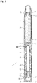
- Figure 1 shows a sectional view of a drug delivery device 1.
- the drug delivery device 1 comprises a cartridge retaining part 2, and a main housing part 3.
- the proximal end of the cartridge retaining part 2 and the distal end of the main housing 3 are secured together by any suitable means known to the person skilled in the art.
- the cartridge retaining part 2 is secured within the distal end of the main housing part 3.
- a cartridge 4 from which a number of doses of a medicinal product may be dispensed is provided in the cartridge retaining part 2.
- a piston 5 is retained in the proximal end of the cartridge 4.
- a removable cap 22 is releasably retained over the distal end of the cartridge retaining part 2.
- the removable cap 22 is optionally provided with one or more window apertures 25 through which the position of the piston 5 within the cartridge 4 can be viewed.
- the distal end of the cartridge retaining part 2 in the illustrated embodiment is provided with a distal threaded region 6 designed for the attachment of a suitable needle assembly (not shown) to enable medicament to be dispensed from the cartridge 4.
- the main housing part 3 is provided with an internal housing 7.
- the internal housing 7 is secured against rotational and axial movement with respect to the main housing part 3.
- the internal housing 7 may be formed integrally with the main housing part 3.
- the internal housing 7 is provided with a circular opening 8.
- a thread 32 is arranged at the opening 8 of the internal housing 7.
- the internal housing 7 is configured as a piston rod nut.
- the circular opening 8 comprises a series of part threads rather than a complete thread.
- a first thread 9 is formed at the distal end of the piston rod 10.
- the piston rod 10 is of generally circular cross-section.
- the first thread 9 of the piston rod 10 extends through and is threadedly engaged with the thread 32 of the circular opening 8 of the internal housing 7.
- a pressure foot 11 is located at the distal end of the piston rod 10.
- the pressure foot 11 is disposed to abut the proximal face of the piston 5.
- a second thread 12 is formed at the proximal end of the piston rod 10.
- the second thread 12 comprises a series of part threads, rather than a complete thread, formed on flexible arms 13 of the piston rod 10.
- the first thread 9 and the second thread 12 are oppositely disposed.
- the first thread 9 is provided with a plurality of features (see Figure 2 ) that cooperate with the thread 32 of the circular opening 8 to prevent movement of the piston rod 10 in the proximal direction during setting of the dose.
- the piston rod 10 is back-winding restrained.
- a drive member 14 extends about the piston rod 10.
- the drive member 14 is configured as a drive sleeve.
- the drive member 14 comprises a threaded part 15 of a generally cylindrical cross-section.
- An actuator 16 is located at a proximal end of the drive member 14.
- the threaded part 15 and the actuator 16 are secured to each other to prevent rotational and/or axial movement there between.
- the drive member 14 may be a unitary component consisting of an integrated threaded part 15 and actuator 16.
- the drive member 14 is moved in a proximal direction.
- a user may pull the actuator 16 in a proximal direction out of the main housing part 3.
- the threaded part 15 is provided with a longitudinally extending helical thread 17 formed on the internal cylindrical surface.
- the flank of the proximal side of the helical thread 17 is designed to maintain contact with the second thread 12 of the piston rod 10 when dispensing a dose, whilst the flank of the distal side of the helical thread 17 is designed to allow the second thread 12 of the piston rod 10 to disengage when setting a dose. In this way the helical thread 17 of the threaded part 15 is releasably engaged with the second thread 12 of the piston rod 10.
- the drive member 14 has a plurality of features formed on the external surface designed to move axially within the guide slots of the main housing 3. These guide slots define the extent of permissible axial movement of the drive member 14 with respect to the housing part 3. In the illustrated embodiment the guide slots also prevent rotational movement of the drive member 14 relative to the main housing part 3.
- the actuator 16 has a plurality of grip surfaces 18 and a dispensing face 19.
- the main housing part 3 may be provided with a window aperture through which graphical status indicators, provided on the drive member 14, can be viewed.
- a user grips the grip surfaces 18 of the drive member 14. The user then pulls the drive member 14 in a proximal direction away from the main housing part 3.
- the piston rod 10 is prevented from moving proximally by the thread 32 of the circular opening 8 of the internal housing 7 interacting with thread features on the first thread 9 of the piston rod 10 or by any other suitable means.
- the first thread 9 and the second thread 12 of the piston rod 10 axially and rotationally constrain the piston rod 10 as long as the relative position of the internal housing 7 and the drive sleeve 14 is maintained.
- the second thread 12 of the piston rod 10 is displaced radially inwards by the flank of the distal side of helical thread 17 of the drive member 14.
- the proximal travel of the drive member 14 is limited by the guide slots (not shown) of the internal housing 7 or of the main housing 3 to a distance corresponding to essentially one thread pitch of the helical thread 17 of the drive member 14.
- the second thread 12 of the piston rod 10 engages with the helical thread 17 under the action of the flexible arms 13 of the piston rod 10.
- the drive member 14 is displaced a distance essentially equal to one pitch of the helical thread 17 of the drive member 14 in the proximal direction relative to the piston rod 10.
- the user may then dispense this dose by depressing the dispensing face 19 of the actuator 16.
- the drive member 14 is moved axially in the distal direction relative to the main housing part 3.
- the piston rod 10 is caused to rotate with respect to the internal housing 7 by the axial movement of the drive member 14 in the distal direction.
- the piston rod 10 rotates, the first thread 9 of the piston rod 10 rotates within the threaded circular opening 8 of the internal housing 7 causing the piston rod 10 to move axially in the distal direction with respect to the internal housing 7.
- the piston rod 10 In addition to advancing, the piston rod 10 also helically retracts partially back into the drive member 14. Thereby, the axial displacement of the drive member 14 is larger than the axial displacement of the piston rod 10.
- the distal axial movement of the piston rod 10 causes the pressure foot 11 to bear against the piston 5 of the cartridge 4 causing a dose of medicament to be dispensed through an attached needle.
- the distal travel of the drive member 14 is limited by the guide slots or by a stop surface (not shown) of the internal housing 7.
- Visual feedback regarding dose dispensing may be indicated by an optional graphical status indicator, provided on the drive member 14, which can be viewed through an optional window aperture in the main housing part 3.
- Further doses may be delivered as required up to a pre-determined maximum number of doses.
- the piston rod 10, the drive member 14 and the internal housing 7 are shown in a more detailed view in Figure 2 .
- the first thread 9 of the piston rod 10 has flat portions 31.
- the thread 32 of the internal housing 7 interacts with the flat portions 31.
- the interaction of the internal housing 7 with the flat portions 31 of the piston rod 10 is configured to axially constrain the piston rod 10 during the setting of a dose.
- the piston rod 10 is prevented from moving in a proximal direction together with the drive sleeve 14 during the setting of a dose.
- the first thread 9 of piston rod 10 may have a shallow pitch, such that the interface between the piston rod 10 and the internal housing 7 would be non-overhaulable.
- Figures 3 and 4 show a stop mechanism 40 of the assembly 30.
- the stop mechanism 40 is configured to inhibit the setting of a dose after an available amount of a drug has been dispensed from the device.
- the stop mechanism 40 inhibits the setting of a dose when the cartridge 4 is empty
- the stop mechanism 40 gives a feedback to a user that the device is empty. For example 15 doses of a drug may be delivered from the device 1. The setting of a sixteenth dose may be inhibited.
- the stop mechanism comprises a stop element 27.
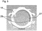
- the stop element 27 is an integral part of the drive member 14. As shown in Figure 5 , the stop element 27 is configured as a protrusion 29 on an internal surface of the drive member 14. In particular, the stop element 27 comprises two protrusions 29. The two protrusions 29 are oppositely disposed. The second protrusion 29 of the stop element 27, which is arranged oppositely to the first protrusion 29, adds radial stability to the mechanism. Furthermore, the drive member 14 may be a symmetrical component. The stop element 27 is arranged at a distal section of the drive member 14.
- an axial movement of the drive member 14 in a proximal direction is constrained.
- an axial movement of the drive member 14 is constrained after a last dose has been dispensed from the device.
- an axial movement of the actuator 16 is also constrained.
- a limited axial movement of the drive member 14 and the actuator 16 is still possible. Such a movement may be greater than zero, but less than a regular dose setting movement. The limited axial movement may be possible due to manufacturing tolerances.
- the assembly 30 is shown in a state when a last dose has been dispensed.
- the piston rod 10 comprises a last dose stop 37.
- the last dose stop 37 is configured as a protrusion on the piston rod 10.
- the last dose stop 37 may comprise two protrusions which are oppositely disposed on the piston rod 10.
- the last dose stop is arranged above the stop element 27, seen from a dispensing end of the assembly. Furthermore, the last dose stop 37 is arranged with an axial distance to the stop element 27.
- the drive member 14 moves in a proximal direction and the stop element 27 abuts the last dose stop 37 of the piston rod 10, as shown in Figure 4 .
- the stop element 27 abuts the last dose stop 37, no further movement of the drive member 14 in a dose setting direction is possible.
- the last dose stop 37 is formed such that it at least partially encompasses the stop member 27.
- the protrusion of the last dose stop 37 comprises the form of a pocket.
- Figures 6 and 7 show a sectional view of the drive member 14 and the piston rod 10.
- Figure 6 shows the piston rod 10 and the drive member 14 in a state when a dose has been set or before the setting of a dose.
- the helical thread 17 of the drive member 14 is engaged with the second thread 12 of the piston rod 10.
- Figure 7 shows the piston rod 10 and the drive member 14 during the setting of a dose. During the setting of a dose, the helical thread 17 of the drive member 14 is not engaged with the second thread 12 of the piston rod 10.
- the drive member 14 comprises ramped surfaces 33.
- the ramped surfaces 33 slide over the flexible arms 13 of the piston rod 10 during the setting of a dose, as shown in Figure 7 .
- the force applied to the flexible arms 13 of the piston rod 10 by the ramped surfaces 33 induces a torque on the piston rod 10.
- piston rod 10 comprises a guiding feature 26.
- the guiding feature 26 is configured to interact with the stop element 27 during the setting of a dose.
- the guiding feature 26 of the piston rod 10 is shown in Figures 2 to 4 and in Figures 8 to 11 .
- the guiding feature 26 comprises a plurality of splines 28.
- the splines 28 are arranged in a row with a distance to each other.
- the guiding feature 26 comprises three rows (not shown) of splines 28.
- the tree rows are equally distributed around the outer circumference of the piston rod 10.
- Figure 8 shows a section of the piston rod 10 and one protrusion 29 of the stop element 27.
- Figure 8 shows a state during the setting of a dose.
- the drive member 14 is cut away for clarity reasons except from the protrusion 29.
- the stop element 27 of the drive member 14 abuts the guiding feature 26 of the piston rod 10.
- the abutment of the drive member 14 and the guiding feature 26 results from the torque which is induced on the piston rod 10 during the setting of a dose.
- the direction of the torque which is applied to the piston rod 10 is indicated by arrow 35.
- the stop element 27 may pass two or more splines 28 during one setting movement.
- the axial distance of these splines 28 is less than an axial extension of the stop element 27. Thereby, the stop element 27 may not pass between two splines 28 during the setting of a dose.
- the splines 28 are arranged directly adjacent to the first thread 9 of the piston rod 10.
- Figure 9 shows the piston rod 10 and the protrusion 29 of Figure 8 in a state when a dose has been set. In this state, the stop element 27 does not abut the guiding feature 26 anymore.
- the piston rod 10 rotates with respect to the drive member 14.
- the stop element 27 performs a helical movement along the piston rod 10.
- the protrusions 29 of the stop element 27 move through between the spline features 28 of the guiding feature.
- the helical movement of the stop element is indicated by arrow 36 in Figure 3 .
- Figures 10 and 11 show the second protrusion 29 of the stop element 27 and the piston rod during the setting of a dose and after the setting of a dose, analogously to Figures 8 and 9 .
Landscapes
- Health & Medical Sciences (AREA)
- Vascular Medicine (AREA)
- Engineering & Computer Science (AREA)
- Anesthesiology (AREA)
- Biomedical Technology (AREA)
- Heart & Thoracic Surgery (AREA)
- Hematology (AREA)
- Life Sciences & Earth Sciences (AREA)
- Animal Behavior & Ethology (AREA)
- General Health & Medical Sciences (AREA)
- Public Health (AREA)
- Veterinary Medicine (AREA)
- Infusion, Injection, And Reservoir Apparatuses (AREA)
Priority Applications (2)
| Application Number | Priority Date | Filing Date | Title |
|---|---|---|---|
| PL14708556T PL2968781T3 (pl) | 2013-03-11 | 2014-03-10 | Zespół do urządzenia do dostarczania leku |
| EP14708556.7A EP2968781B1 (en) | 2013-03-11 | 2014-03-10 | Assembly for a drug delivery device |
Applications Claiming Priority (3)
| Application Number | Priority Date | Filing Date | Title |
|---|---|---|---|
| EP13158512 | 2013-03-11 | ||
| EP14708556.7A EP2968781B1 (en) | 2013-03-11 | 2014-03-10 | Assembly for a drug delivery device |
| PCT/EP2014/054521 WO2014139910A1 (en) | 2013-03-11 | 2014-03-10 | Assembly for a drug delivery device |
Publications (2)
| Publication Number | Publication Date |
|---|---|
| EP2968781A1 EP2968781A1 (en) | 2016-01-20 |
| EP2968781B1 true EP2968781B1 (en) | 2019-04-24 |
Family
ID=47845805
Family Applications (1)
| Application Number | Title | Priority Date | Filing Date |
|---|---|---|---|
| EP14708556.7A Active EP2968781B1 (en) | 2013-03-11 | 2014-03-10 | Assembly for a drug delivery device |
Country Status (19)
| Country | Link |
|---|---|
| US (1) | US10201663B2 (pt) |
| EP (1) | EP2968781B1 (pt) |
| JP (1) | JP6352316B2 (pt) |
| KR (1) | KR102282541B1 (pt) |
| CN (1) | CN105025963B (pt) |
| AR (1) | AR095194A1 (pt) |
| AU (1) | AU2014231036B2 (pt) |
| BR (1) | BR112015020816B1 (pt) |
| DK (1) | DK2968781T3 (pt) |
| ES (1) | ES2735329T3 (pt) |
| HK (1) | HK1213511A1 (pt) |
| HU (1) | HUE044075T2 (pt) |
| IL (1) | IL240546B (pt) |
| MX (1) | MX363431B (pt) |
| PL (1) | PL2968781T3 (pt) |
| RU (1) | RU2673378C2 (pt) |
| TR (1) | TR201910216T4 (pt) |
| TW (1) | TWI644693B (pt) |
| WO (1) | WO2014139910A1 (pt) |
Families Citing this family (3)
| Publication number | Priority date | Publication date | Assignee | Title |
|---|---|---|---|---|
| EP3181169A1 (en) * | 2015-12-14 | 2017-06-21 | Sanofi-Aventis Deutschland GmbH | Drive mechanism for an injection device |
| EP3181171A1 (en) * | 2015-12-14 | 2017-06-21 | Sanofi-Aventis Deutschland GmbH | Drive mechanism for an injection device |
| CH714883A1 (de) * | 2018-04-12 | 2019-10-15 | Medicel Ag | Injektor mit zwei Betriebsmodi, insbesondere geeignet zum Injizieren einer intraokularen Linse. |
Family Cites Families (36)
| Publication number | Priority date | Publication date | Assignee | Title |
|---|---|---|---|---|
| US533575A (en) | 1895-02-05 | wilkens | ||
| US5226895A (en) | 1989-06-05 | 1993-07-13 | Eli Lilly And Company | Multiple dose injection pen |
| GB9007113D0 (en) | 1990-03-29 | 1990-05-30 | Sams Bernard | Dispensing device |
| EP0525525B1 (de) | 1991-07-24 | 1995-05-03 | Medico Development Investment Company | Injektor |
| DK175491D0 (da) | 1991-10-18 | 1991-10-18 | Novo Nordisk As | Apparat |
| US5279586A (en) | 1992-02-04 | 1994-01-18 | Becton, Dickinson And Company | Reusable medication delivery pen |
| US5320609A (en) | 1992-12-07 | 1994-06-14 | Habley Medical Technology Corporation | Automatic pharmaceutical dispensing syringe |
| US5383865A (en) | 1993-03-15 | 1995-01-24 | Eli Lilly And Company | Medication dispensing device |
| ZA941881B (en) | 1993-04-02 | 1995-09-18 | Lilly Co Eli | Manifold medication injection apparatus and method |
| US5582598A (en) | 1994-09-19 | 1996-12-10 | Becton Dickinson And Company | Medication delivery pen with variable increment dose scale |
| CA2213682C (en) | 1995-03-07 | 2009-10-06 | Eli Lilly And Company | Recyclable medication dispensing device |
| US5688251A (en) | 1995-09-19 | 1997-11-18 | Becton Dickinson And Company | Cartridge loading and priming mechanism for a pen injector |
| US5674204A (en) | 1995-09-19 | 1997-10-07 | Becton Dickinson And Company | Medication delivery pen cap actuated dose delivery clutch |
| DE19730999C1 (de) | 1997-07-18 | 1998-12-10 | Disetronic Licensing Ag | Dosierknopfsicherung an einer Vorrichtung zur dosierten Verabreichung eines injizierbaren Produkts |
| US5921966A (en) | 1997-08-11 | 1999-07-13 | Becton Dickinson And Company | Medication delivery pen having an improved clutch assembly |
| EP1003581B1 (en) | 1998-01-30 | 2000-11-08 | Novo Nordisk A/S | An injection syringe |
| US6221053B1 (en) | 1998-02-20 | 2001-04-24 | Becton, Dickinson And Company | Multi-featured medication delivery pen |
| US6096010A (en) | 1998-02-20 | 2000-08-01 | Becton, Dickinson And Company | Repeat-dose medication delivery pen |
| US6248095B1 (en) | 1998-02-23 | 2001-06-19 | Becton, Dickinson And Company | Low-cost medication delivery pen |
| EP1218042B1 (en) | 1999-08-05 | 2006-02-22 | Becton Dickinson and Company | Medication delivery pen |
| GB0007071D0 (en) | 2000-03-24 | 2000-05-17 | Sams Bernard | One-way clutch mechanisms and injector devices |
| US6663602B2 (en) | 2000-06-16 | 2003-12-16 | Novo Nordisk A/S | Injection device |
| US6899699B2 (en) | 2001-01-05 | 2005-05-31 | Novo Nordisk A/S | Automatic injection device with reset feature |
| AU2002353761A1 (en) | 2001-03-27 | 2003-03-18 | Eli Lilly And Company | Medication dispensing apparatus configured for pull to set dose and push to inject set dose functionality |
| EP2275158B1 (en) | 2001-05-16 | 2013-01-23 | Eli Lilly and Company | Medication injector apparatus |
| CA2448726C (en) * | 2001-07-16 | 2012-01-31 | Eli Lilly And Company | Medication dispensing apparatus configured for rotate to prime and pull/push to inject functionality |
| GB0304823D0 (en) | 2003-03-03 | 2003-04-09 | Dca Internat Ltd | Improvements in and relating to a pen-type injector |
| DE102004063647A1 (de) | 2004-12-31 | 2006-07-20 | Tecpharma Licensing Ag | Vorrichtung zur dosierten Verabreichung eines fluiden Produkts mit Kupplung |
| EP1923085A1 (en) * | 2006-11-17 | 2008-05-21 | Sanofi-Aventis Deutschland GmbH | Dosing and drive mechanism for drug delivery device |
| US8647309B2 (en) | 2008-05-02 | 2014-02-11 | Sanofi-Aventis Deutschland Gmbh | Medication delivery device |
| JP5453394B2 (ja) | 2008-05-02 | 2014-03-26 | サノフィ−アベンティス・ドイチュラント・ゲゼルシャフト・ミット・ベシュレンクテル・ハフツング | 薬剤送達デバイス |
| MX2010011251A (es) | 2008-05-02 | 2010-11-12 | Sanofi Aventis Deutschland | Dispositivo de suministro de medicacion. |
| TWI415640B (zh) * | 2009-10-01 | 2013-11-21 | Shl Group Ab | 藥物輸送裝置 |
| TWI415645B (zh) * | 2009-11-10 | 2013-11-21 | Shl Group Ab | 藥物輸送裝置 |
| EP2566539A1 (en) * | 2010-05-04 | 2013-03-13 | Sanofi-Aventis Deutschland GmbH | Drive mechanism with a low friction coating for a drug delivery device |
| AR083299A1 (es) * | 2010-10-06 | 2013-02-13 | Sanofi Aventis Deutschland | Mecanismo de impulso para un dispositivo de administracion de farmacos y dispositivo de administracion de farmacos |
-
2014
- 2014-03-07 TW TW103107807A patent/TWI644693B/zh not_active IP Right Cessation
- 2014-03-10 MX MX2015012571A patent/MX363431B/es unknown
- 2014-03-10 EP EP14708556.7A patent/EP2968781B1/en active Active
- 2014-03-10 PL PL14708556T patent/PL2968781T3/pl unknown
- 2014-03-10 CN CN201480012707.2A patent/CN105025963B/zh active Active
- 2014-03-10 US US14/770,852 patent/US10201663B2/en active Active
- 2014-03-10 AU AU2014231036A patent/AU2014231036B2/en active Active
- 2014-03-10 HU HUE14708556A patent/HUE044075T2/hu unknown
- 2014-03-10 BR BR112015020816-9A patent/BR112015020816B1/pt active IP Right Grant
- 2014-03-10 RU RU2015142664A patent/RU2673378C2/ru active
- 2014-03-10 ES ES14708556T patent/ES2735329T3/es active Active
- 2014-03-10 DK DK14708556.7T patent/DK2968781T3/da active
- 2014-03-10 JP JP2015562053A patent/JP6352316B2/ja active Active
- 2014-03-10 WO PCT/EP2014/054521 patent/WO2014139910A1/en active Application Filing
- 2014-03-10 TR TR2019/10216T patent/TR201910216T4/tr unknown
- 2014-03-10 KR KR1020157027907A patent/KR102282541B1/ko active IP Right Grant
- 2014-03-10 AR ARP140100800A patent/AR095194A1/es not_active Application Discontinuation
-
2015
- 2015-08-12 IL IL240546A patent/IL240546B/en active IP Right Grant
-
2016
- 2016-02-11 HK HK16101480.7A patent/HK1213511A1/zh unknown
Non-Patent Citations (1)
| Title |
|---|
| None * |
Also Published As
| Publication number | Publication date |
|---|---|
| RU2673378C2 (ru) | 2018-11-26 |
| RU2015142664A3 (pt) | 2018-03-12 |
| CN105025963B (zh) | 2019-12-03 |
| BR112015020816B1 (pt) | 2021-10-13 |
| HK1213511A1 (zh) | 2016-07-08 |
| KR20150126927A (ko) | 2015-11-13 |
| TR201910216T4 (tr) | 2019-08-21 |
| TWI644693B (zh) | 2018-12-21 |
| CN105025963A (zh) | 2015-11-04 |
| US10201663B2 (en) | 2019-02-12 |
| ES2735329T3 (es) | 2019-12-18 |
| DK2968781T3 (da) | 2019-07-15 |
| IL240546A0 (en) | 2015-10-29 |
| PL2968781T3 (pl) | 2019-09-30 |
| AR095194A1 (es) | 2015-09-30 |
| WO2014139910A1 (en) | 2014-09-18 |
| TW201509457A (zh) | 2015-03-16 |
| EP2968781A1 (en) | 2016-01-20 |
| MX363431B (es) | 2019-03-22 |
| RU2015142664A (ru) | 2017-04-25 |
| IL240546B (en) | 2020-04-30 |
| BR112015020816A2 (pt) | 2017-07-18 |
| AU2014231036B2 (en) | 2018-07-05 |
| US20160008551A1 (en) | 2016-01-14 |
| JP6352316B2 (ja) | 2018-07-04 |
| JP2016509896A (ja) | 2016-04-04 |
| AU2014231036A1 (en) | 2015-09-24 |
| MX2015012571A (es) | 2016-01-12 |
| KR102282541B1 (ko) | 2021-07-29 |
| HUE044075T2 (hu) | 2019-09-30 |
Similar Documents
| Publication | Publication Date | Title |
|---|---|---|
| EP2854908B1 (en) | Drive mechanism for a drug delivery device and drug delivery device | |
| EP3003432B1 (en) | Drive assembly for a drug delivery device and drug delivery device | |
| EP2996743B1 (en) | Assembly for a drug delivery device and drug delivery device | |
| EP2854907B1 (en) | Drive mechanism for a drug delivery device and drug delivery device | |
| US20160317749A1 (en) | Assembly for a drug delivery device and drug delivery device | |
| EP2968780B1 (en) | Assembly for a drug delivery device | |
| EP3003439B1 (en) | Assembly for a drug delivery device and drug delivery device | |
| EP2968781B1 (en) | Assembly for a drug delivery device | |
| US10357613B2 (en) | Assembly for a drug delivery device | |
| EP2950857B1 (en) | Assembly for a drug delivery device | |
| EP3068470B1 (en) | Assembly for a drug delivery device and drug delivery device |
Legal Events
| Date | Code | Title | Description |
|---|---|---|---|
| PUAI | Public reference made under article 153(3) epc to a published international application that has entered the european phase |
Free format text: ORIGINAL CODE: 0009012 |
|
| 17P | Request for examination filed |
Effective date: 20151012 |
|
| AK | Designated contracting states |
Kind code of ref document: A1 Designated state(s): AL AT BE BG CH CY CZ DE DK EE ES FI FR GB GR HR HU IE IS IT LI LT LU LV MC MK MT NL NO PL PT RO RS SE SI SK SM TR |
|
| AX | Request for extension of the european patent |
Extension state: BA ME |
|
| DAX | Request for extension of the european patent (deleted) | ||
| REG | Reference to a national code |
Ref country code: HK Ref legal event code: DE Ref document number: 1213511 Country of ref document: HK |
|
| GRAP | Despatch of communication of intention to grant a patent |
Free format text: ORIGINAL CODE: EPIDOSNIGR1 |
|
| STAA | Information on the status of an ep patent application or granted ep patent |
Free format text: STATUS: GRANT OF PATENT IS INTENDED |
|
| INTG | Intention to grant announced |
Effective date: 20180518 |
|
| GRAJ | Information related to disapproval of communication of intention to grant by the applicant or resumption of examination proceedings by the epo deleted |
Free format text: ORIGINAL CODE: EPIDOSDIGR1 |
|
| STAA | Information on the status of an ep patent application or granted ep patent |
Free format text: STATUS: REQUEST FOR EXAMINATION WAS MADE |
|
| INTC | Intention to grant announced (deleted) | ||
| GRAP | Despatch of communication of intention to grant a patent |
Free format text: ORIGINAL CODE: EPIDOSNIGR1 |
|
| STAA | Information on the status of an ep patent application or granted ep patent |
Free format text: STATUS: GRANT OF PATENT IS INTENDED |
|
| INTG | Intention to grant announced |
Effective date: 20180926 |
|
| GRAS | Grant fee paid |
Free format text: ORIGINAL CODE: EPIDOSNIGR3 |
|
| GRAA | (expected) grant |
Free format text: ORIGINAL CODE: 0009210 |
|
| STAA | Information on the status of an ep patent application or granted ep patent |
Free format text: STATUS: THE PATENT HAS BEEN GRANTED |
|
| AK | Designated contracting states |
Kind code of ref document: B1 Designated state(s): AL AT BE BG CH CY CZ DE DK EE ES FI FR GB GR HR HU IE IS IT LI LT LU LV MC MK MT NL NO PL PT RO RS SE SI SK SM TR |
|
| REG | Reference to a national code |
Ref country code: GB Ref legal event code: FG4D |
|
| REG | Reference to a national code |
Ref country code: CH Ref legal event code: EP |
|
| REG | Reference to a national code |
Ref country code: AT Ref legal event code: REF Ref document number: 1123383 Country of ref document: AT Kind code of ref document: T Effective date: 20190515 Ref country code: IE Ref legal event code: FG4D |
|
| REG | Reference to a national code |
Ref country code: DE Ref legal event code: R096 Ref document number: 602014045265 Country of ref document: DE |
|
| REG | Reference to a national code |
Ref country code: DK Ref legal event code: T3 Effective date: 20190711 |
|
| REG | Reference to a national code |
Ref country code: NL Ref legal event code: FP |
|
| REG | Reference to a national code |
Ref country code: SE Ref legal event code: TRGR |
|
| REG | Reference to a national code |
Ref country code: LT Ref legal event code: MG4D |
|
| REG | Reference to a national code |
Ref country code: HU Ref legal event code: AG4A Ref document number: E044075 Country of ref document: HU Ref country code: NO Ref legal event code: T2 Effective date: 20190424 |
|
| PG25 | Lapsed in a contracting state [announced via postgrant information from national office to epo] |
Ref country code: FI Free format text: LAPSE BECAUSE OF FAILURE TO SUBMIT A TRANSLATION OF THE DESCRIPTION OR TO PAY THE FEE WITHIN THE PRESCRIBED TIME-LIMIT Effective date: 20190424 Ref country code: AL Free format text: LAPSE BECAUSE OF FAILURE TO SUBMIT A TRANSLATION OF THE DESCRIPTION OR TO PAY THE FEE WITHIN THE PRESCRIBED TIME-LIMIT Effective date: 20190424 Ref country code: PT Free format text: LAPSE BECAUSE OF FAILURE TO SUBMIT A TRANSLATION OF THE DESCRIPTION OR TO PAY THE FEE WITHIN THE PRESCRIBED TIME-LIMIT Effective date: 20190824 Ref country code: HR Free format text: LAPSE BECAUSE OF FAILURE TO SUBMIT A TRANSLATION OF THE DESCRIPTION OR TO PAY THE FEE WITHIN THE PRESCRIBED TIME-LIMIT Effective date: 20190424 Ref country code: LT Free format text: LAPSE BECAUSE OF FAILURE TO SUBMIT A TRANSLATION OF THE DESCRIPTION OR TO PAY THE FEE WITHIN THE PRESCRIBED TIME-LIMIT Effective date: 20190424 |
|
| PG25 | Lapsed in a contracting state [announced via postgrant information from national office to epo] |
Ref country code: BG Free format text: LAPSE BECAUSE OF FAILURE TO SUBMIT A TRANSLATION OF THE DESCRIPTION OR TO PAY THE FEE WITHIN THE PRESCRIBED TIME-LIMIT Effective date: 20190724 Ref country code: RS Free format text: LAPSE BECAUSE OF FAILURE TO SUBMIT A TRANSLATION OF THE DESCRIPTION OR TO PAY THE FEE WITHIN THE PRESCRIBED TIME-LIMIT Effective date: 20190424 Ref country code: LV Free format text: LAPSE BECAUSE OF FAILURE TO SUBMIT A TRANSLATION OF THE DESCRIPTION OR TO PAY THE FEE WITHIN THE PRESCRIBED TIME-LIMIT Effective date: 20190424 |
|
| REG | Reference to a national code |
Ref country code: ES Ref legal event code: FG2A Ref document number: 2735329 Country of ref document: ES Kind code of ref document: T3 Effective date: 20191218 |
|
| PG25 | Lapsed in a contracting state [announced via postgrant information from national office to epo] |
Ref country code: IS Free format text: LAPSE BECAUSE OF FAILURE TO SUBMIT A TRANSLATION OF THE DESCRIPTION OR TO PAY THE FEE WITHIN THE PRESCRIBED TIME-LIMIT Effective date: 20190824 |
|
| REG | Reference to a national code |
Ref country code: GR Ref legal event code: EP Ref document number: 20190402244 Country of ref document: GR Effective date: 20191128 |
|
| REG | Reference to a national code |
Ref country code: DE Ref legal event code: R097 Ref document number: 602014045265 Country of ref document: DE |
|
| PG25 | Lapsed in a contracting state [announced via postgrant information from national office to epo] |
Ref country code: SK Free format text: LAPSE BECAUSE OF FAILURE TO SUBMIT A TRANSLATION OF THE DESCRIPTION OR TO PAY THE FEE WITHIN THE PRESCRIBED TIME-LIMIT Effective date: 20190424 Ref country code: RO Free format text: LAPSE BECAUSE OF FAILURE TO SUBMIT A TRANSLATION OF THE DESCRIPTION OR TO PAY THE FEE WITHIN THE PRESCRIBED TIME-LIMIT Effective date: 20190424 Ref country code: EE Free format text: LAPSE BECAUSE OF FAILURE TO SUBMIT A TRANSLATION OF THE DESCRIPTION OR TO PAY THE FEE WITHIN THE PRESCRIBED TIME-LIMIT Effective date: 20190424 |
|
| PG25 | Lapsed in a contracting state [announced via postgrant information from national office to epo] |
Ref country code: SM Free format text: LAPSE BECAUSE OF FAILURE TO SUBMIT A TRANSLATION OF THE DESCRIPTION OR TO PAY THE FEE WITHIN THE PRESCRIBED TIME-LIMIT Effective date: 20190424 |
|
| PLBE | No opposition filed within time limit |
Free format text: ORIGINAL CODE: 0009261 |
|
| STAA | Information on the status of an ep patent application or granted ep patent |
Free format text: STATUS: NO OPPOSITION FILED WITHIN TIME LIMIT |
|
| 26N | No opposition filed |
Effective date: 20200127 |
|
| PG25 | Lapsed in a contracting state [announced via postgrant information from national office to epo] |
Ref country code: SI Free format text: LAPSE BECAUSE OF FAILURE TO SUBMIT A TRANSLATION OF THE DESCRIPTION OR TO PAY THE FEE WITHIN THE PRESCRIBED TIME-LIMIT Effective date: 20190424 |
|
| REG | Reference to a national code |
Ref country code: AT Ref legal event code: UEP Ref document number: 1123383 Country of ref document: AT Kind code of ref document: T Effective date: 20190424 |
|
| PG25 | Lapsed in a contracting state [announced via postgrant information from national office to epo] |
Ref country code: MC Free format text: LAPSE BECAUSE OF FAILURE TO SUBMIT A TRANSLATION OF THE DESCRIPTION OR TO PAY THE FEE WITHIN THE PRESCRIBED TIME-LIMIT Effective date: 20190424 |
|
| PG25 | Lapsed in a contracting state [announced via postgrant information from national office to epo] |
Ref country code: LU Free format text: LAPSE BECAUSE OF NON-PAYMENT OF DUE FEES Effective date: 20200310 |
|
| PG25 | Lapsed in a contracting state [announced via postgrant information from national office to epo] |
Ref country code: MT Free format text: LAPSE BECAUSE OF FAILURE TO SUBMIT A TRANSLATION OF THE DESCRIPTION OR TO PAY THE FEE WITHIN THE PRESCRIBED TIME-LIMIT Effective date: 20190424 Ref country code: CY Free format text: LAPSE BECAUSE OF FAILURE TO SUBMIT A TRANSLATION OF THE DESCRIPTION OR TO PAY THE FEE WITHIN THE PRESCRIBED TIME-LIMIT Effective date: 20190424 |
|
| PG25 | Lapsed in a contracting state [announced via postgrant information from national office to epo] |
Ref country code: MK Free format text: LAPSE BECAUSE OF FAILURE TO SUBMIT A TRANSLATION OF THE DESCRIPTION OR TO PAY THE FEE WITHIN THE PRESCRIBED TIME-LIMIT Effective date: 20190424 |
|
| PGFP | Annual fee paid to national office [announced via postgrant information from national office to epo] |
Ref country code: NO Payment date: 20230309 Year of fee payment: 10 Ref country code: FR Payment date: 20230110 Year of fee payment: 10 Ref country code: DK Payment date: 20230314 Year of fee payment: 10 |
|
| PGFP | Annual fee paid to national office [announced via postgrant information from national office to epo] |
Ref country code: TR Payment date: 20230309 Year of fee payment: 10 Ref country code: SE Payment date: 20230110 Year of fee payment: 10 Ref country code: PL Payment date: 20230102 Year of fee payment: 10 Ref country code: IT Payment date: 20230213 Year of fee payment: 10 Ref country code: BE Payment date: 20230216 Year of fee payment: 10 |
|
| PGFP | Annual fee paid to national office [announced via postgrant information from national office to epo] |
Ref country code: ES Payment date: 20230407 Year of fee payment: 10 Ref country code: CH Payment date: 20230401 Year of fee payment: 10 |
|
| PGFP | Annual fee paid to national office [announced via postgrant information from national office to epo] |
Ref country code: NL Payment date: 20240108 Year of fee payment: 11 |
|
| PGFP | Annual fee paid to national office [announced via postgrant information from national office to epo] |
Ref country code: GR Payment date: 20240213 Year of fee payment: 11 |
|
| PGFP | Annual fee paid to national office [announced via postgrant information from national office to epo] |
Ref country code: IE Payment date: 20240103 Year of fee payment: 11 |
|
| PGFP | Annual fee paid to national office [announced via postgrant information from national office to epo] |
Ref country code: AT Payment date: 20240226 Year of fee payment: 11 |
|
| PGFP | Annual fee paid to national office [announced via postgrant information from national office to epo] |
Ref country code: HU Payment date: 20240205 Year of fee payment: 11 Ref country code: DE Payment date: 20231229 Year of fee payment: 11 Ref country code: CZ Payment date: 20240216 Year of fee payment: 11 Ref country code: GB Payment date: 20240108 Year of fee payment: 11 |