EP2950857B1 - Assembly for a drug delivery device - Google Patents
Assembly for a drug delivery device Download PDFInfo
- Publication number
- EP2950857B1 EP2950857B1 EP14702046.5A EP14702046A EP2950857B1 EP 2950857 B1 EP2950857 B1 EP 2950857B1 EP 14702046 A EP14702046 A EP 14702046A EP 2950857 B1 EP2950857 B1 EP 2950857B1
- Authority
- EP
- European Patent Office
- Prior art keywords
- piston rod
- drive member
- snap feature
- movement
- actuator
- Prior art date
- Legal status (The legal status is an assumption and is not a legal conclusion. Google has not performed a legal analysis and makes no representation as to the accuracy of the status listed.)
- Active
Links
- 238000012377 drug delivery Methods 0.000 title claims description 40
- 239000003814 drug Substances 0.000 claims description 25
- 229940079593 drug Drugs 0.000 claims description 23
- 230000003993 interaction Effects 0.000 claims description 4
- JUFFVKRROAPVBI-PVOYSMBESA-N chembl1210015 Chemical compound C([C@@H](C(=O)N[C@@H]([C@@H](C)CC)C(=O)N[C@@H](CCC(O)=O)C(=O)N[C@@H](CC=1C2=CC=CC=C2NC=1)C(=O)N[C@@H](CC(C)C)C(=O)N[C@@H](CCCCN)C(=O)N[C@@H](CC(=O)N[C@H]1[C@@H]([C@@H](O)[C@H](O[C@H]2[C@@H]([C@@H](O)[C@@H](O)[C@@H](CO[C@]3(O[C@@H](C[C@H](O)[C@H](O)CO)[C@H](NC(C)=O)[C@@H](O)C3)C(O)=O)O2)O)[C@@H](CO)O1)NC(C)=O)C(=O)NCC(=O)NCC(=O)N1[C@@H](CCC1)C(=O)N[C@@H](CO)C(=O)N[C@@H](CO)C(=O)NCC(=O)N[C@@H](C)C(=O)N1[C@@H](CCC1)C(=O)N1[C@@H](CCC1)C(=O)N1[C@@H](CCC1)C(=O)N[C@@H](CO)C(N)=O)NC(=O)[C@H](CC(C)C)NC(=O)[C@H](CCCNC(N)=N)NC(=O)[C@@H](NC(=O)[C@H](C)NC(=O)[C@H](CCC(O)=O)NC(=O)[C@H](CCC(O)=O)NC(=O)[C@H](CCC(O)=O)NC(=O)[C@H](CCSC)NC(=O)[C@H](CCC(N)=O)NC(=O)[C@H](CCCCN)NC(=O)[C@H](CO)NC(=O)[C@H](CC(C)C)NC(=O)[C@H](CC(O)=O)NC(=O)[C@H](CO)NC(=O)[C@@H](NC(=O)[C@H](CC=1C=CC=CC=1)NC(=O)[C@@H](NC(=O)CNC(=O)[C@H](CCC(O)=O)NC(=O)CNC(=O)[C@@H](N)CC=1NC=NC=1)[C@@H](C)O)[C@@H](C)O)C(C)C)C1=CC=CC=C1 JUFFVKRROAPVBI-PVOYSMBESA-N 0.000 description 54
- 108010011459 Exenatide Proteins 0.000 description 50
- 229960001519 exenatide Drugs 0.000 description 50
- 101000976075 Homo sapiens Insulin Proteins 0.000 description 22
- QEFRNWWLZKMPFJ-YGVKFDHGSA-N L-methionine S-oxide Chemical compound CS(=O)CC[C@H](N)C(O)=O QEFRNWWLZKMPFJ-YGVKFDHGSA-N 0.000 description 22
- PBGKTOXHQIOBKM-FHFVDXKLSA-N insulin (human) Chemical compound C([C@@H](C(=O)N[C@@H](CC(C)C)C(=O)N[C@H]1CSSC[C@H]2C(=O)N[C@H](C(=O)N[C@@H](CO)C(=O)N[C@H](C(=O)N[C@H](C(N[C@@H](CO)C(=O)N[C@@H](CC(C)C)C(=O)N[C@@H](CC=3C=CC(O)=CC=3)C(=O)N[C@@H](CCC(N)=O)C(=O)N[C@@H](CC(C)C)C(=O)N[C@@H](CCC(O)=O)C(=O)N[C@@H](CC(N)=O)C(=O)N[C@@H](CC=3C=CC(O)=CC=3)C(=O)N[C@@H](CSSC[C@H](NC(=O)[C@H](C(C)C)NC(=O)[C@H](CC(C)C)NC(=O)[C@H](CC=3C=CC(O)=CC=3)NC(=O)[C@H](CC(C)C)NC(=O)[C@H](C)NC(=O)[C@H](CCC(O)=O)NC(=O)[C@H](C(C)C)NC(=O)[C@H](CC(C)C)NC(=O)[C@H](CC=3NC=NC=3)NC(=O)[C@H](CO)NC(=O)CNC1=O)C(=O)NCC(=O)N[C@@H](CCC(O)=O)C(=O)N[C@@H](CCCNC(N)=N)C(=O)NCC(=O)N[C@@H](CC=1C=CC=CC=1)C(=O)N[C@@H](CC=1C=CC=CC=1)C(=O)N[C@@H](CC=1C=CC(O)=CC=1)C(=O)N[C@@H]([C@@H](C)O)C(=O)N1[C@@H](CCC1)C(=O)N[C@@H](CCCCN)C(=O)N[C@@H]([C@@H](C)O)C(O)=O)C(=O)N[C@@H](CC(N)=O)C(O)=O)=O)CSSC[C@@H](C(N2)=O)NC(=O)[C@H](CCC(N)=O)NC(=O)[C@H](CCC(O)=O)NC(=O)[C@H](C(C)C)NC(=O)[C@@H](NC(=O)CN)[C@@H](C)CC)[C@@H](C)CC)[C@@H](C)O)NC(=O)[C@H](CCC(N)=O)NC(=O)[C@H](CC(N)=O)NC(=O)[C@@H](NC(=O)[C@@H](N)CC=1C=CC=CC=1)C(C)C)C1=CN=CN1 PBGKTOXHQIOBKM-FHFVDXKLSA-N 0.000 description 21
- 239000012634 fragment Substances 0.000 description 10
- 235000001014 amino acid Nutrition 0.000 description 9
- 150000001413 amino acids Chemical class 0.000 description 9
- 150000003839 salts Chemical class 0.000 description 8
- 239000000427 antigen Substances 0.000 description 7
- 102000036639 antigens Human genes 0.000 description 7
- 108091007433 antigens Proteins 0.000 description 7
- 150000001875 compounds Chemical class 0.000 description 7
- NOESYZHRGYRDHS-UHFFFAOYSA-N insulin Chemical compound N1C(=O)C(NC(=O)C(CCC(N)=O)NC(=O)C(CCC(O)=O)NC(=O)C(C(C)C)NC(=O)C(NC(=O)CN)C(C)CC)CSSCC(C(NC(CO)C(=O)NC(CC(C)C)C(=O)NC(CC=2C=CC(O)=CC=2)C(=O)NC(CCC(N)=O)C(=O)NC(CC(C)C)C(=O)NC(CCC(O)=O)C(=O)NC(CC(N)=O)C(=O)NC(CC=2C=CC(O)=CC=2)C(=O)NC(CSSCC(NC(=O)C(C(C)C)NC(=O)C(CC(C)C)NC(=O)C(CC=2C=CC(O)=CC=2)NC(=O)C(CC(C)C)NC(=O)C(C)NC(=O)C(CCC(O)=O)NC(=O)C(C(C)C)NC(=O)C(CC(C)C)NC(=O)C(CC=2NC=NC=2)NC(=O)C(CO)NC(=O)CNC2=O)C(=O)NCC(=O)NC(CCC(O)=O)C(=O)NC(CCCNC(N)=N)C(=O)NCC(=O)NC(CC=3C=CC=CC=3)C(=O)NC(CC=3C=CC=CC=3)C(=O)NC(CC=3C=CC(O)=CC=3)C(=O)NC(C(C)O)C(=O)N3C(CCC3)C(=O)NC(CCCCN)C(=O)NC(C)C(O)=O)C(=O)NC(CC(N)=O)C(O)=O)=O)NC(=O)C(C(C)CC)NC(=O)C(CO)NC(=O)C(C(C)O)NC(=O)C1CSSCC2NC(=O)C(CC(C)C)NC(=O)C(NC(=O)C(CCC(N)=O)NC(=O)C(CC(N)=O)NC(=O)C(NC(=O)C(N)CC=1C=CC=CC=1)C(C)C)CC1=CN=CN1 NOESYZHRGYRDHS-UHFFFAOYSA-N 0.000 description 5
- 108090000765 processed proteins & peptides Proteins 0.000 description 5
- 108060003951 Immunoglobulin Proteins 0.000 description 4
- 206010012601 diabetes mellitus Diseases 0.000 description 4
- 102000018358 immunoglobulin Human genes 0.000 description 4
- 108010047041 Complementarity Determining Regions Proteins 0.000 description 3
- 210000003719 b-lymphocyte Anatomy 0.000 description 3
- 150000004676 glycans Chemical class 0.000 description 3
- 229940088597 hormone Drugs 0.000 description 3
- 239000005556 hormone Substances 0.000 description 3
- 239000003055 low molecular weight heparin Substances 0.000 description 3
- 229940127215 low-molecular weight heparin Drugs 0.000 description 3
- 229920001282 polysaccharide Polymers 0.000 description 3
- 239000005017 polysaccharide Substances 0.000 description 3
- 208000004476 Acute Coronary Syndrome Diseases 0.000 description 2
- 208000002249 Diabetes Complications Diseases 0.000 description 2
- 206010012689 Diabetic retinopathy Diseases 0.000 description 2
- 108010088406 Glucagon-Like Peptides Proteins 0.000 description 2
- 108090001061 Insulin Proteins 0.000 description 2
- 102000004877 Insulin Human genes 0.000 description 2
- 241000124008 Mammalia Species 0.000 description 2
- 239000002253 acid Substances 0.000 description 2
- 150000001447 alkali salts Chemical class 0.000 description 2
- 125000000151 cysteine group Chemical group N[C@@H](CS)C(=O)* 0.000 description 2
- 230000029087 digestion Effects 0.000 description 2
- LMHMJYMCGJNXRS-IOPUOMRJSA-N exendin-3 Chemical compound C([C@@H](C(=O)N[C@@H]([C@@H](C)CC)C(=O)N[C@@H](CCC(O)=O)C(=O)N[C@@H](CC=1C2=CC=CC=C2NC=1)C(=O)N[C@@H](CC(C)C)C(=O)N[C@@H](CCCCN)C(=O)N[C@@H](CC(N)=O)C(=O)NCC(=O)NCC(=O)N1[C@@H](CCC1)C(=O)N[C@@H](CO)C(=O)N[C@@H](CO)C(=O)NCC(=O)N[C@@H](C)C(=O)N1[C@@H](CCC1)C(=O)N1[C@@H](CCC1)C(=O)N1[C@@H](CCC1)C(=O)N[C@@H](CO)C(N)=O)NC(=O)[C@H](CC(C)C)NC(=O)[C@H](CCCNC(N)=N)NC(=O)[C@@H](NC(=O)[C@H](C)NC(=O)[C@H](CCC(O)=O)NC(=O)[C@H](CCC(O)=O)NC(=O)[C@H](CCC(O)=O)NC(=O)[C@H](CCSC)NC(=O)[C@H](CCC(N)=O)NC(=O)[C@H](CCCCN)NC(=O)[C@H](CO)NC(=O)[C@H](CC(C)C)NC(=O)[C@H](CC(O)=O)NC(=O)[C@H](CO)NC(=O)[C@@H](NC(=O)[C@H](CC=1C=CC=CC=1)NC(=O)[C@@H](NC(=O)CNC(=O)[C@H](CC(O)=O)NC(=O)[C@H](CO)NC(=O)[C@@H](N)CC=1N=CNC=1)[C@H](C)O)[C@H](C)O)C(C)C)C1=CC=CC=C1 LMHMJYMCGJNXRS-IOPUOMRJSA-N 0.000 description 2
- 229940125396 insulin Drugs 0.000 description 2
- 239000000203 mixture Substances 0.000 description 2
- 239000000178 monomer Substances 0.000 description 2
- 102000004196 processed proteins & peptides Human genes 0.000 description 2
- 238000011321 prophylaxis Methods 0.000 description 2
- 230000000717 retained effect Effects 0.000 description 2
- 239000012453 solvate Substances 0.000 description 2
- 238000011282 treatment Methods 0.000 description 2
- 230000000007 visual effect Effects 0.000 description 2
- KIUKXJAPPMFGSW-DNGZLQJQSA-N (2S,3S,4S,5R,6R)-6-[(2S,3R,4R,5S,6R)-3-Acetamido-2-[(2S,3S,4R,5R,6R)-6-[(2R,3R,4R,5S,6R)-3-acetamido-2,5-dihydroxy-6-(hydroxymethyl)oxan-4-yl]oxy-2-carboxy-4,5-dihydroxyoxan-3-yl]oxy-5-hydroxy-6-(hydroxymethyl)oxan-4-yl]oxy-3,4,5-trihydroxyoxane-2-carboxylic acid Chemical compound CC(=O)N[C@H]1[C@H](O)O[C@H](CO)[C@@H](O)[C@@H]1O[C@H]1[C@H](O)[C@@H](O)[C@H](O[C@H]2[C@@H]([C@@H](O[C@H]3[C@@H]([C@@H](O)[C@H](O)[C@H](O3)C(O)=O)O)[C@H](O)[C@@H](CO)O2)NC(C)=O)[C@@H](C(O)=O)O1 KIUKXJAPPMFGSW-DNGZLQJQSA-N 0.000 description 1
- 125000004169 (C1-C6) alkyl group Chemical group 0.000 description 1
- 125000001831 (C6-C10) heteroaryl group Chemical group 0.000 description 1
- 208000035285 Allergic Seasonal Rhinitis Diseases 0.000 description 1
- QGZKDVFQNNGYKY-UHFFFAOYSA-O Ammonium Chemical compound [NH4+] QGZKDVFQNNGYKY-UHFFFAOYSA-O 0.000 description 1
- 206010002383 Angina Pectoris Diseases 0.000 description 1
- 201000001320 Atherosclerosis Diseases 0.000 description 1
- 108010017384 Blood Proteins Proteins 0.000 description 1
- 102000004506 Blood Proteins Human genes 0.000 description 1
- 108010037003 Buserelin Proteins 0.000 description 1
- 125000000882 C2-C6 alkenyl group Chemical group 0.000 description 1
- 125000000041 C6-C10 aryl group Chemical group 0.000 description 1
- 108010000437 Deamino Arginine Vasopressin Proteins 0.000 description 1
- 208000005189 Embolism Diseases 0.000 description 1
- 108090000790 Enzymes Proteins 0.000 description 1
- 102000004190 Enzymes Human genes 0.000 description 1
- 102000012673 Follicle Stimulating Hormone Human genes 0.000 description 1
- 108010079345 Follicle Stimulating Hormone Proteins 0.000 description 1
- 102000003886 Glycoproteins Human genes 0.000 description 1
- 108090000288 Glycoproteins Proteins 0.000 description 1
- 102400000932 Gonadoliberin-1 Human genes 0.000 description 1
- 108010069236 Goserelin Proteins 0.000 description 1
- BLCLNMBMMGCOAS-URPVMXJPSA-N Goserelin Chemical compound C([C@@H](C(=O)N[C@H](COC(C)(C)C)C(=O)N[C@@H](CC(C)C)C(=O)N[C@@H](CCCN=C(N)N)C(=O)N1[C@@H](CCC1)C(=O)NNC(N)=O)NC(=O)[C@H](CO)NC(=O)[C@H](CC=1C2=CC=CC=C2NC=1)NC(=O)[C@H](CC=1NC=NC=1)NC(=O)[C@H]1NC(=O)CC1)C1=CC=C(O)C=C1 BLCLNMBMMGCOAS-URPVMXJPSA-N 0.000 description 1
- HTTJABKRGRZYRN-UHFFFAOYSA-N Heparin Chemical compound OC1C(NC(=O)C)C(O)OC(COS(O)(=O)=O)C1OC1C(OS(O)(=O)=O)C(O)C(OC2C(C(OS(O)(=O)=O)C(OC3C(C(O)C(O)C(O3)C(O)=O)OS(O)(=O)=O)C(CO)O2)NS(O)(=O)=O)C(C(O)=O)O1 HTTJABKRGRZYRN-UHFFFAOYSA-N 0.000 description 1
- 101500026183 Homo sapiens Gonadoliberin-1 Proteins 0.000 description 1
- 102000002265 Human Growth Hormone Human genes 0.000 description 1
- 108010000521 Human Growth Hormone Proteins 0.000 description 1
- 239000000854 Human Growth Hormone Substances 0.000 description 1
- 108010021625 Immunoglobulin Fragments Proteins 0.000 description 1
- 102000008394 Immunoglobulin Fragments Human genes 0.000 description 1
- 102000013463 Immunoglobulin Light Chains Human genes 0.000 description 1
- 108010065825 Immunoglobulin Light Chains Proteins 0.000 description 1
- 206010061218 Inflammation Diseases 0.000 description 1
- 108010000817 Leuprolide Proteins 0.000 description 1
- XVVOERDUTLJJHN-UHFFFAOYSA-N Lixisenatide Chemical compound C=1NC2=CC=CC=C2C=1CC(C(=O)NC(CC(C)C)C(=O)NC(CCCCN)C(=O)NC(CC(N)=O)C(=O)NCC(=O)NCC(=O)N1C(CCC1)C(=O)NC(CO)C(=O)NC(CO)C(=O)NCC(=O)NC(C)C(=O)N1C(CCC1)C(=O)N1C(CCC1)C(=O)NC(CO)C(=O)NC(CCCCN)C(=O)NC(CCCCN)C(=O)NC(CCCCN)C(=O)NC(CCCCN)C(=O)NC(CCCCN)C(=O)NC(CCCCN)C(N)=O)NC(=O)C(CCC(O)=O)NC(=O)C(C(C)CC)NC(=O)C(NC(=O)C(CC(C)C)NC(=O)C(CCCNC(N)=N)NC(=O)C(NC(=O)C(C)NC(=O)C(CCC(O)=O)NC(=O)C(CCC(O)=O)NC(=O)C(CCC(O)=O)NC(=O)C(CCSC)NC(=O)C(CCC(N)=O)NC(=O)C(CCCCN)NC(=O)C(CO)NC(=O)C(CC(C)C)NC(=O)C(CC(O)=O)NC(=O)C(CO)NC(=O)C(NC(=O)C(CC=1C=CC=CC=1)NC(=O)C(NC(=O)CNC(=O)C(CCC(O)=O)NC(=O)CNC(=O)C(N)CC=1NC=NC=1)C(C)O)C(C)O)C(C)C)CC1=CC=CC=C1 XVVOERDUTLJJHN-UHFFFAOYSA-N 0.000 description 1
- 102000009151 Luteinizing Hormone Human genes 0.000 description 1
- 108010073521 Luteinizing Hormone Proteins 0.000 description 1
- 108010021717 Nafarelin Proteins 0.000 description 1
- 206010028980 Neoplasm Diseases 0.000 description 1
- 108091034117 Oligonucleotide Proteins 0.000 description 1
- 108090000526 Papain Proteins 0.000 description 1
- 102000057297 Pepsin A Human genes 0.000 description 1
- 108090000284 Pepsin A Proteins 0.000 description 1
- ONIBWKKTOPOVIA-UHFFFAOYSA-N Proline Natural products OC(=O)C1CCCN1 ONIBWKKTOPOVIA-UHFFFAOYSA-N 0.000 description 1
- 239000004365 Protease Substances 0.000 description 1
- 208000010378 Pulmonary Embolism Diseases 0.000 description 1
- 108010010056 Terlipressin Proteins 0.000 description 1
- 208000001435 Thromboembolism Diseases 0.000 description 1
- 108010050144 Triptorelin Pamoate Proteins 0.000 description 1
- 239000003513 alkali Substances 0.000 description 1
- 125000000539 amino acid group Chemical group 0.000 description 1
- 239000005557 antagonist Substances 0.000 description 1
- 229960002719 buserelin Drugs 0.000 description 1
- CUWODFFVMXJOKD-UVLQAERKSA-N buserelin Chemical compound CCNC(=O)[C@@H]1CCCN1C(=O)[C@H](CCCN=C(N)N)NC(=O)[C@H](CC(C)C)NC(=O)[C@@H](COC(C)(C)C)NC(=O)[C@@H](NC(=O)[C@H](CO)NC(=O)[C@H](CC=1C2=CC=CC=C2NC=1)NC(=O)[C@H](CC=1NC=NC=1)NC(=O)[C@H]1NC(=O)CC1)CC1=CC=C(O)C=C1 CUWODFFVMXJOKD-UVLQAERKSA-N 0.000 description 1
- 201000011510 cancer Diseases 0.000 description 1
- 150000001720 carbohydrates Chemical class 0.000 description 1
- 235000014633 carbohydrates Nutrition 0.000 description 1
- 125000003178 carboxy group Chemical group [H]OC(*)=O 0.000 description 1
- 150000001768 cations Chemical class 0.000 description 1
- 230000000295 complement effect Effects 0.000 description 1
- 235000018417 cysteine Nutrition 0.000 description 1
- 230000000881 depressing effect Effects 0.000 description 1
- 229960004281 desmopressin Drugs 0.000 description 1
- NFLWUMRGJYTJIN-NXBWRCJVSA-N desmopressin Chemical compound C([C@H]1C(=O)N[C@H](C(N[C@@H](CC(N)=O)C(=O)N[C@@H](CSSCCC(=O)N[C@@H](CC=2C=CC(O)=CC=2)C(=O)N1)C(=O)N1[C@@H](CCC1)C(=O)N[C@@H](CCCNC(N)=N)C(=O)NCC(N)=O)=O)CCC(=O)N)C1=CC=CC=C1 NFLWUMRGJYTJIN-NXBWRCJVSA-N 0.000 description 1
- 208000037265 diseases, disorders, signs and symptoms Diseases 0.000 description 1
- 208000035475 disorder Diseases 0.000 description 1
- 229960005153 enoxaparin sodium Drugs 0.000 description 1
- 229940088598 enzyme Drugs 0.000 description 1
- 108010015174 exendin 3 Proteins 0.000 description 1
- 229960001442 gonadorelin Drugs 0.000 description 1
- XLXSAKCOAKORKW-AQJXLSMYSA-N gonadorelin Chemical compound C([C@@H](C(=O)NCC(=O)N[C@@H](CC(C)C)C(=O)N[C@@H](CCCNC(N)=N)C(=O)N1[C@@H](CCC1)C(=O)NCC(N)=O)NC(=O)[C@H](CO)NC(=O)[C@H](CC=1C2=CC=CC=C2NC=1)NC(=O)[C@H](CC=1N=CNC=1)NC(=O)[C@H]1NC(=O)CC1)C1=CC=C(O)C=C1 XLXSAKCOAKORKW-AQJXLSMYSA-N 0.000 description 1
- 229960002913 goserelin Drugs 0.000 description 1
- 229960002897 heparin Drugs 0.000 description 1
- 229920000669 heparin Polymers 0.000 description 1
- 229920002674 hyaluronan Polymers 0.000 description 1
- 229960003160 hyaluronic acid Drugs 0.000 description 1
- 150000004677 hydrates Chemical class 0.000 description 1
- 229910052739 hydrogen Inorganic materials 0.000 description 1
- 239000001257 hydrogen Substances 0.000 description 1
- 125000004435 hydrogen atom Chemical class [H]* 0.000 description 1
- 239000000960 hypophysis hormone Substances 0.000 description 1
- 210000003016 hypothalamus Anatomy 0.000 description 1
- 229940072221 immunoglobulins Drugs 0.000 description 1
- 230000004054 inflammatory process Effects 0.000 description 1
- 238000002347 injection Methods 0.000 description 1
- 239000007924 injection Substances 0.000 description 1
- 239000004026 insulin derivative Substances 0.000 description 1
- GFIJNRVAKGFPGQ-LIJARHBVSA-N leuprolide Chemical compound CCNC(=O)[C@@H]1CCCN1C(=O)[C@H](CCCNC(N)=N)NC(=O)[C@H](CC(C)C)NC(=O)[C@@H](CC(C)C)NC(=O)[C@@H](NC(=O)[C@H](CO)NC(=O)[C@H](CC=1C2=CC=CC=C2NC=1)NC(=O)[C@H](CC=1N=CNC=1)NC(=O)[C@H]1NC(=O)CC1)CC1=CC=C(O)C=C1 GFIJNRVAKGFPGQ-LIJARHBVSA-N 0.000 description 1
- 229960004338 leuprorelin Drugs 0.000 description 1
- 239000007788 liquid Substances 0.000 description 1
- XVVOERDUTLJJHN-IAEQDCLQSA-N lixisenatide Chemical compound C([C@@H](C(=O)N[C@@H]([C@@H](C)CC)C(=O)N[C@@H](CCC(O)=O)C(=O)N[C@@H](CC=1C2=CC=CC=C2NC=1)C(=O)N[C@@H](CC(C)C)C(=O)N[C@@H](CCCCN)C(=O)N[C@@H](CC(N)=O)C(=O)NCC(=O)NCC(=O)N1[C@@H](CCC1)C(=O)N[C@@H](CO)C(=O)N[C@@H](CO)C(=O)NCC(=O)N[C@@H](C)C(=O)N1[C@@H](CCC1)C(=O)N1[C@@H](CCC1)C(=O)N[C@@H](CO)C(=O)N[C@@H](CCCCN)C(=O)N[C@@H](CCCCN)C(=O)N[C@@H](CCCCN)C(=O)N[C@@H](CCCCN)C(=O)N[C@@H](CCCCN)C(=O)N[C@@H](CCCCN)C(N)=O)NC(=O)[C@H](CC(C)C)NC(=O)[C@H](CCCNC(N)=N)NC(=O)[C@@H](NC(=O)[C@H](C)NC(=O)[C@H](CCC(O)=O)NC(=O)[C@H](CCC(O)=O)NC(=O)[C@H](CCC(O)=O)NC(=O)[C@H](CCSC)NC(=O)[C@H](CCC(N)=O)NC(=O)[C@H](CCCCN)NC(=O)[C@H](CO)NC(=O)[C@H](CC(C)C)NC(=O)[C@H](CC(O)=O)NC(=O)[C@H](CO)NC(=O)[C@@H](NC(=O)[C@H](CC=1C=CC=CC=1)NC(=O)[C@@H](NC(=O)CNC(=O)[C@H](CCC(O)=O)NC(=O)CNC(=O)[C@@H](N)CC=1N=CNC=1)[C@@H](C)O)[C@@H](C)O)C(C)C)C1=CC=CC=C1 XVVOERDUTLJJHN-IAEQDCLQSA-N 0.000 description 1
- 108010004367 lixisenatide Proteins 0.000 description 1
- 229960001093 lixisenatide Drugs 0.000 description 1
- 208000002780 macular degeneration Diseases 0.000 description 1
- 229940126601 medicinal product Drugs 0.000 description 1
- 208000010125 myocardial infarction Diseases 0.000 description 1
- RWHUEXWOYVBUCI-ITQXDASVSA-N nafarelin Chemical compound C([C@@H](C(=O)N[C@H](CC=1C=C2C=CC=CC2=CC=1)C(=O)N[C@@H](CC(C)C)C(=O)N[C@@H](CCCN=C(N)N)C(=O)N1[C@@H](CCC1)C(=O)NCC(N)=O)NC(=O)[C@H](CO)NC(=O)[C@H](CC=1C2=CC=CC=C2NC=1)NC(=O)[C@H](CC=1NC=NC=1)NC(=O)[C@H]1NC(=O)CC1)C1=CC=C(O)C=C1 RWHUEXWOYVBUCI-ITQXDASVSA-N 0.000 description 1
- 229960002333 nafarelin Drugs 0.000 description 1
- 229940055729 papain Drugs 0.000 description 1
- 235000019834 papain Nutrition 0.000 description 1
- 229940111202 pepsin Drugs 0.000 description 1
- 239000008194 pharmaceutical composition Substances 0.000 description 1
- 229920001184 polypeptide Polymers 0.000 description 1
- 125000002924 primary amino group Chemical group [H]N([H])* 0.000 description 1
- 125000001500 prolyl group Chemical group [H]N1C([H])(C(=O)[*])C([H])([H])C([H])([H])C1([H])[H] 0.000 description 1
- 230000002797 proteolythic effect Effects 0.000 description 1
- 230000001105 regulatory effect Effects 0.000 description 1
- 206010039073 rheumatoid arthritis Diseases 0.000 description 1
- 229960004532 somatropin Drugs 0.000 description 1
- 241000894007 species Species 0.000 description 1
- 241001223854 teleost fish Species 0.000 description 1
- 229960003813 terlipressin Drugs 0.000 description 1
- BENFXAYNYRLAIU-QSVFAHTRSA-N terlipressin Chemical compound NCCCC[C@@H](C(=O)NCC(N)=O)NC(=O)[C@@H]1CCCN1C(=O)[C@H]1NC(=O)[C@H](CC(N)=O)NC(=O)[C@H](CCC(N)=O)NC(=O)[C@H](CC=2C=CC=CC=2)NC(=O)[C@H](CC=2C=CC(O)=CC=2)NC(=O)[C@@H](NC(=O)CNC(=O)CNC(=O)CN)CSSC1 BENFXAYNYRLAIU-QSVFAHTRSA-N 0.000 description 1
- CIJQTPFWFXOSEO-NDMITSJXSA-J tetrasodium;(2r,3r,4s)-2-[(2r,3s,4r,5r,6s)-5-acetamido-6-[(1r,2r,3r,4r)-4-[(2r,3s,4r,5r,6r)-5-acetamido-6-[(4r,5r,6r)-2-carboxylato-4,5-dihydroxy-6-[[(1r,3r,4r,5r)-3-hydroxy-4-(sulfonatoamino)-6,8-dioxabicyclo[3.2.1]octan-2-yl]oxy]oxan-3-yl]oxy-2-(hydroxy Chemical compound [Na+].[Na+].[Na+].[Na+].O([C@@H]1[C@@H](COS(O)(=O)=O)O[C@@H]([C@@H]([C@H]1O)NC(C)=O)O[C@@H]1C(C[C@H]([C@@H]([C@H]1O)O)O[C@@H]1[C@@H](CO)O[C@H](OC2C(O[C@@H](OC3[C@@H]([C@@H](NS([O-])(=O)=O)[C@@H]4OC[C@H]3O4)O)[C@H](O)[C@H]2O)C([O-])=O)[C@H](NC(C)=O)[C@H]1C)C([O-])=O)[C@@H]1OC(C([O-])=O)=C[C@H](O)[C@H]1O CIJQTPFWFXOSEO-NDMITSJXSA-J 0.000 description 1
- 229960004824 triptorelin Drugs 0.000 description 1
- VXKHXGOKWPXYNA-PGBVPBMZSA-N triptorelin Chemical compound C([C@@H](C(=O)N[C@H](CC=1C2=CC=CC=C2NC=1)C(=O)N[C@@H](CC(C)C)C(=O)N[C@@H](CCCNC(N)=N)C(=O)N1[C@@H](CCC1)C(=O)NCC(N)=O)NC(=O)[C@H](CO)NC(=O)[C@H](CC=1C2=CC=CC=C2NC=1)NC(=O)[C@H](CC=1N=CNC=1)NC(=O)[C@H]1NC(=O)CC1)C1=CC=C(O)C=C1 VXKHXGOKWPXYNA-PGBVPBMZSA-N 0.000 description 1
- 229960005486 vaccine Drugs 0.000 description 1
- 210000003462 vein Anatomy 0.000 description 1
Images

Classifications
-
- A—HUMAN NECESSITIES
- A61—MEDICAL OR VETERINARY SCIENCE; HYGIENE
- A61M—DEVICES FOR INTRODUCING MEDIA INTO, OR ONTO, THE BODY; DEVICES FOR TRANSDUCING BODY MEDIA OR FOR TAKING MEDIA FROM THE BODY; DEVICES FOR PRODUCING OR ENDING SLEEP OR STUPOR
- A61M5/00—Devices for bringing media into the body in a subcutaneous, intra-vascular or intramuscular way; Accessories therefor, e.g. filling or cleaning devices, arm-rests
- A61M5/178—Syringes
- A61M5/31—Details
- A61M5/315—Pistons; Piston-rods; Guiding, blocking or restricting the movement of the rod or piston; Appliances on the rod for facilitating dosing ; Dosing mechanisms
- A61M5/31501—Means for blocking or restricting the movement of the rod or piston
-
- A—HUMAN NECESSITIES
- A61—MEDICAL OR VETERINARY SCIENCE; HYGIENE
- A61M—DEVICES FOR INTRODUCING MEDIA INTO, OR ONTO, THE BODY; DEVICES FOR TRANSDUCING BODY MEDIA OR FOR TAKING MEDIA FROM THE BODY; DEVICES FOR PRODUCING OR ENDING SLEEP OR STUPOR
- A61M5/00—Devices for bringing media into the body in a subcutaneous, intra-vascular or intramuscular way; Accessories therefor, e.g. filling or cleaning devices, arm-rests
- A61M5/178—Syringes
- A61M5/31—Details
- A61M5/315—Pistons; Piston-rods; Guiding, blocking or restricting the movement of the rod or piston; Appliances on the rod for facilitating dosing ; Dosing mechanisms
- A61M5/31533—Dosing mechanisms, i.e. setting a dose
- A61M5/31535—Means improving security or handling thereof, e.g. blocking means, means preventing insufficient dosing, means allowing correction of overset dose
- A61M5/31541—Means preventing setting of a dose beyond the amount remaining in the cartridge
-
- A—HUMAN NECESSITIES
- A61—MEDICAL OR VETERINARY SCIENCE; HYGIENE
- A61M—DEVICES FOR INTRODUCING MEDIA INTO, OR ONTO, THE BODY; DEVICES FOR TRANSDUCING BODY MEDIA OR FOR TAKING MEDIA FROM THE BODY; DEVICES FOR PRODUCING OR ENDING SLEEP OR STUPOR
- A61M5/00—Devices for bringing media into the body in a subcutaneous, intra-vascular or intramuscular way; Accessories therefor, e.g. filling or cleaning devices, arm-rests
- A61M5/178—Syringes
- A61M5/31—Details
- A61M5/315—Pistons; Piston-rods; Guiding, blocking or restricting the movement of the rod or piston; Appliances on the rod for facilitating dosing ; Dosing mechanisms
- A61M5/31525—Dosing
- A61M5/31528—Dosing by means of rotational movements, e.g. screw-thread mechanisms
-
- A—HUMAN NECESSITIES
- A61—MEDICAL OR VETERINARY SCIENCE; HYGIENE
- A61M—DEVICES FOR INTRODUCING MEDIA INTO, OR ONTO, THE BODY; DEVICES FOR TRANSDUCING BODY MEDIA OR FOR TAKING MEDIA FROM THE BODY; DEVICES FOR PRODUCING OR ENDING SLEEP OR STUPOR
- A61M5/00—Devices for bringing media into the body in a subcutaneous, intra-vascular or intramuscular way; Accessories therefor, e.g. filling or cleaning devices, arm-rests
- A61M5/178—Syringes
- A61M5/31—Details
- A61M5/315—Pistons; Piston-rods; Guiding, blocking or restricting the movement of the rod or piston; Appliances on the rod for facilitating dosing ; Dosing mechanisms
- A61M5/31565—Administration mechanisms, i.e. constructional features, modes of administering a dose
- A61M5/31576—Constructional features or modes of drive mechanisms for piston rods
- A61M5/31583—Constructional features or modes of drive mechanisms for piston rods based on rotational translation, i.e. movement of piston rod is caused by relative rotation between the user activated actuator and the piston rod
- A61M5/31585—Constructional features or modes of drive mechanisms for piston rods based on rotational translation, i.e. movement of piston rod is caused by relative rotation between the user activated actuator and the piston rod performed by axially moving actuator, e.g. an injection button
-
- A—HUMAN NECESSITIES
- A61—MEDICAL OR VETERINARY SCIENCE; HYGIENE
- A61M—DEVICES FOR INTRODUCING MEDIA INTO, OR ONTO, THE BODY; DEVICES FOR TRANSDUCING BODY MEDIA OR FOR TAKING MEDIA FROM THE BODY; DEVICES FOR PRODUCING OR ENDING SLEEP OR STUPOR
- A61M5/00—Devices for bringing media into the body in a subcutaneous, intra-vascular or intramuscular way; Accessories therefor, e.g. filling or cleaning devices, arm-rests
- A61M5/50—Devices for bringing media into the body in a subcutaneous, intra-vascular or intramuscular way; Accessories therefor, e.g. filling or cleaning devices, arm-rests having means for preventing re-use, or for indicating if defective, used, tampered with or unsterile
- A61M5/5013—Means for blocking the piston or the fluid passageway to prevent illegal refilling of a syringe
- A61M5/502—Means for blocking the piston or the fluid passageway to prevent illegal refilling of a syringe for blocking the piston
-
- A—HUMAN NECESSITIES
- A61—MEDICAL OR VETERINARY SCIENCE; HYGIENE
- A61M—DEVICES FOR INTRODUCING MEDIA INTO, OR ONTO, THE BODY; DEVICES FOR TRANSDUCING BODY MEDIA OR FOR TAKING MEDIA FROM THE BODY; DEVICES FOR PRODUCING OR ENDING SLEEP OR STUPOR
- A61M5/00—Devices for bringing media into the body in a subcutaneous, intra-vascular or intramuscular way; Accessories therefor, e.g. filling or cleaning devices, arm-rests
- A61M5/178—Syringes
- A61M5/31—Details
- A61M5/315—Pistons; Piston-rods; Guiding, blocking or restricting the movement of the rod or piston; Appliances on the rod for facilitating dosing ; Dosing mechanisms
- A61M5/31533—Dosing mechanisms, i.e. setting a dose
- A61M5/31535—Means improving security or handling thereof, e.g. blocking means, means preventing insufficient dosing, means allowing correction of overset dose
- A61M5/31536—Blocking means to immobilize a selected dose, e.g. to administer equal doses
- A61M2005/3154—Blocking means to immobilize a selected dose, e.g. to administer equal doses limiting maximum permissible dose
Definitions
- the present disclosure relates to an assembly for a drug delivery device.
- a drug delivery device and an assembly for a drug delivery device are described for example in documents WO 2008/058665 A1 and WO 2012/017036 A1 .
- An assembly for a drug delivery device comprising an actuator which is configured to perform a setting movement in order to set a dose and which is configured to perform a dispense movement in order to dispense a dose.
- the assembly further comprises a piston rod which is configured to be moved in a distal direction in order to dispense a dose, and a snap feature which is configured to snap into engagement with the piston rod.
- the snap feature is configured to inhibit a dispense movement of the actuator when a maximum amount of medication has been delivered.
- the maximum amount of medication may be for example the amount of medication available in a cartridge.
- An advantage of a snap feature which is configured to snap into engagement with the piston rod is that the snap feature may permanently lock the assembly. When the assembly is locked, a movement of any component of the assembly may be inhibited.
- the snap feature is configured as a resilient member.
- the snap feature may comprise the shape of a ring.
- the snap feature may be arranged concentrically around the piston rod.
- the snap feature may be in contact with the piston rod throughout the use of the drug delivery device, i.e. also when it is not engaged with the piston rod.
- the snap feature may comprise at least one protrusion which may be in contact with the piston rod.
- the at least one protrusion may be arranged at an inner surface of the snap feature.
- the snap feature may comprise two protrusions, which may be oppositely arranged.
- the snap feature is preloaded due to an interaction with the piston rod.
- the snap feature may be deflected in a radial outward direction due to the presence of the piston rod when the snap feature is not engaged with the piston rod.
- the snap feature is preloaded before snapping into engagement with the piston rod.
- the snap feature may be preloaded throughout the use of the drug delivery device.
- the snap feature is enabled to relax.
- the snap feature may deflect in a radial inward direction, thereby engaging with the piston rod.
- the at least one protrusion of the snap feature may engage with the piston rod.
- the snap feature may still be slightly preloaded or it may be in an undeflected state.
- the snap feature is configured to inhibit a dispense movement of the actuator after a last setting movement when a maximum amount of medication has been delivered. According to a further embodiment, the snap feature is configured to inhibit a setting movement of the actuator after a last dispense movement when a maximum amount of medication has been delivered.
- the setting movement of the actuator may be a translational movement in a proximal direction.
- the setting movement may be an axial, non-rotational movement.
- the setting movement may be a combined axial and rotational movement.
- the setting movement may be a purely rotational movement.
- the dispense movement of the actuator may be a movement in a distal direction, for example a purely axial movement.
- the actuator may be pushed in a distal direction by a user in order to dispense a dose.
- the actuator may be configured as a button.
- proximal direction may describe a direction away from a dispensing end of the device.
- proximal end may be an end which is furthest away from a dispensing end.
- distal direction may describe a direction towards a dispensing end of the device.
- the snap feature is configured to snap into engagement with the piston rod after a last setting movement of the actuator.
- the snap feature may be configured to snap into engagement with the piston rod after a last dispense movement.
- the piston rod comprises at least one recess, wherein the snap feature is configured to engage with the recess.
- the at least one recess of the piston rod may be configured as a hole.
- the recess may extend in a direction which is perpendicular to a longitudinal axis of the device.
- the recess may extend through the piston rod.
- the piston rod may comprise two recesses, which may be oppositely arranged.
- the snap feature may be configured such that the at least one protrusion of the snap feature may engage into the at least one recess of the piston rod, in particular after a last setting or a last dispense movement of the actuator.
- the snap feature is configured to produce an audible click when snapping into engagement with the piston rod.
- the audible click may indicate to a user that a maximum amount of medication has been delivered.
- the audible click may indicate to a user that a last dose is ready to be delivered.
- the assembly comprises a drive member which is configured to drive the piston rod towards a distal end of the device in order to deliver a dose of medication.
- the drive member may be configured as a drive sleeve.
- the drive member may be arranged concentrically around the piston rod.
- the drive member may be coupled with the piston rod, for example by means of a thread.
- the drive member comprises at least one recess, wherein the snap feature is permanently engaged with the at least one recess of the drive member.
- the at least one protrusion of the snap feature is permanently engaged with the at least one recess of the drive member.
- the at least one recess may be configured as a hole.
- the at least one recess may extend through the drive member in a radial direction towards a longitudinal axis of the device.
- the drive member may comprise two recesses, which may be oppositely arranged.
- the snap feature is arranged concentrically around the drive member.
- the snap feature is rotationally and axially fixed with respect to the drive member.
- the snap feature may be fixed with respect to the drive member by means of the at least one protrusion of the snap feature being engaged with the at least one recess of the drive member.
- the drive member may be fixedly coupled to the actuator.
- the drive member and the actuator are manufactured as one part.
- a movement of the actuator may cause a movement of the drive member. Since the drive member and the actuator may be fixedly coupled to each other, the movement of the drive member may correspond to the movement of the actuator.
- the drive member may be moved relative to the piston rod.
- the drive member may be moved along the piston rod in a proximal direction.
- the drive member may perform an axial, non-rotational movement during the setting of a dose.
- the drive member may perform a combined axial and rotational movement.
- the drive member may be rotated along the piston rod.
- the drive member may perform a purely rotational movement with respect to the piston rod.
- a further dispense movement may be inhibited when the snap feature has engaged with the piston rod.
- a further dispense movement may be inhibited by the snap feature in case that the drive member and the piston rod are configured to be moved relative to each other during the dispense movement
- a further dispense movement may be enabled when the snap feature has engaged with the piston rod.
- a further dispense movement may be enabled when the snap feature has engaged with the piston rod in case that the drive member and the piston rod are configured to be fixed with respect to each other during a dispense movement.
- a further setting movement may be inhibited by the snap feature.
- the snap feature may snap into engagement with the piston rod when the drive member is in a most proximal position with respect to the piston rod.
- the snap feature may snap into engagement with the piston rod at the end of a setting movement.
- the piston rod and the drive member may be fixed with respect to each other. In particular, there may be no relative movement between the piston rod and the drive member. In particular, the piston rod and the drive member may be moved together in a distal direction. In an alternative embodiment, the piston rod and the drive member may move relative to each other during the dispense operation. In particular, the piston rod may rotate and axially move with respect to the drive member during the dispensing of a dose. In particular, a further dispense movement may be inhibited when the snap feature has engaged with the piston rod. Alternatively, a further dispense movement may be enabled when the snap feature has engaged with the piston rod.
- the drive member and the piston rod are locked with respect to each other when the snap feature is engaged with the piston rod.
- any relative movement between the drive member and the piston rod is inhibited.
- the snap feature may snap into engagement with the piston rod when the piston rod and the drive member are in a predetermined position with respect to each other.
- the snap feature may be engaged with the piston rod when the at least one recess of the drive member is aligned with the at least one recess of the piston rod.
- the snap feature may be enabled to relax.
- the snap feature may be enabled to deflect in a radial inward direction.
- the at least one protrusion of the snap feature may further move through the at least one recess of the drive member and engage the at least one recess of the piston rod.
- a last setting movement is enabled and a dispense movement is inhibited, after the snap feature has engaged with the piston rod.
- a last dispense movement is enabled and a further setting movement is inhibited after the snap feature has engaged with the piston rod.
- a setting movement and a dispense movement are inhibited after the snap feature has engaged with the piston rod.
- a relative movement between the drive member and the piston rod may be inhibited.
- a movement in a distal direction of the drive member and the piston rod may be inhibited in the case that a dispense operation requires a relative movement of the drive member and the piston rod.
- the device may be locked.
- no further setting or dispense movement may be possible.
- the actuator may protrude from a housing of the assembly. Thereby, an indication may be given to a user that the device is empty.
- a distal movement of the drive member and the piston rod may be enabled.
- a distal movement of the drive member and the piston rod may be enabled in the case that a dispense operation does not involve a relative movement between the drive member and the piston rod.
- an axial, non-rotational movement of the drive member and the piston rod may be enabled.
- a further setting movement may be inhibited after the dispensing of the last dose, since the drive member may not be rotated along the piston rod in a proximal direction.
- the snap feature may engage with the piston rod after a last dispense movement.
- the snap feature may engage with the piston rod in the case that the drive member and the piston rod are moved relative to each other during the dispensing of a dose.
- the piston rod may be moved in a proximal direction with respect to the drive member.
- the piston rod may rotate and axially move in a proximal direction with respect to the drive member. Due to the snap feature engaging with the piston rod, the assembly may be locked after a dispense movement. In particular, a further setting movement and a further dispense movement may be inhibited.
- a drug delivery device comprising an assembly which is configured as previously described.
- the drug delivery device may comprise a snap feature which is configured to snap into engagement with the piston rod, wherein the snap feature is configured to inhibit a dispense movement of the actuator and/or a setting movement after a last dispense movement when a maximum amount of medication has been delivered.
- the drug delivery device may be an injection device.
- the drug delivery device may be a pen-type device.
- the drug delivery device may be a fixed dose device such that the amount of medication which is delivered during one dispense operation is predetermined. In particular, a user may not be enabled to vary the size of the dose.
- the drug delivery device may be a variable dose device, such that the amount of medication which is delivered during one dispense operation may be selected by a user.
- the drug delivery device may be configured for multiple dose applications.
- the medication may be delivered to a user by means of a needle.
- the device may be delivered to a user in a fully assembled condition ready for use.
- the drug delivery device may be a disposable device.
- the term "disposable" means that the drug delivery device cannot be reused after an available amount of medication has been delivered from the drug delivery device.
- the drug delivery device may be configured to deliver a liquid medication.
- the medication may be, for example, insulin.
- dication preferably means a pharmaceutical formulation containing at least one pharmaceutically active compound
- Insulin analogues are for example Gly(A21), Arg(B31), Arg(B32) human insulin; Lys(B3), Glu(B29) human insulin; Lys(B28), Pro(B29) human insulin; Asp(B28) human insulin; human insulin, wherein proline in position B28 is replaced by Asp, Lys, Leu, Val or Ala and wherein in position B29 Lys may be replaced by Pro; Ala(B26) human insulin; Des(B28-B30) human insulin; Des(B27) human insulin and Des(B30) human insulin.
- Insulin derivates are for example B29-N-myristoyl-des(B30) human insulin; B29-N-palmitoyl-des(B30) human insulin; B29-N-myristoyl human insulin; B29-N-palmitoyl human insulin; B28-N-myristoyl LysB28ProB29 human insulin; B28-N-palmitoyl-LysB28ProB29 human insulin; B30-N-myristoyl-ThrB29LysB30 human insulin; B30-N-palmitoyl- ThrB29LysB30 human insulin; B29-N-(N-palmitoyl-Y-glutamyl)-des(B30) human insulin; B29-N-(N-lithocholyl-Y-glutamyl)-des(B30) human insulin; B29-N-( ⁇ -carboxyheptadecanoyl)-des(B30) human insulin and B29-N-( ⁇ -carbox
- Exendin-4 for example means Exendin-4(1-39), a peptide of the sequence H-His-Gly-Glu-Gly-Thr-Phe-Thr-Ser-Asp-Leu-Ser-Lys-Gln-Met-Glu-Glu-Glu-Ala-Val-Arg-Leu-Phe-Ile-Glu-Trp-Leu-Lys-Asn-Gly-Gly-Pro-Ser-Ser-Gly-Ala-Pro-Pro-Pro-Ser-NH2.
- Exendin-4 derivatives are for example selected from the following list of compounds:
- Hormones are for example hypophysis hormones or hypothalamus hormones or regulatory active peptides and their antagonists as listed in Rote Liste, ed. 2008, Chapter 50, such as Gonadotropine (Follitropin, Lutropin, Choriongonadotropin, Menotropin), Somatropine (Somatropin), Desmopressin, Terlipressin, Gonadorelin, Triptorelin, Leuprorelin, Buserelin, Nafarelin, Goserelin.
- Gonadotropine Follitropin, Lutropin, Choriongonadotropin, Menotropin
- Somatropine Somatropin
- Desmopressin Terlipressin
- Gonadorelin Triptorelin
- Leuprorelin Buserelin
- Nafarelin Goserelin.
- a polysaccharide is for example a glucosaminoglycane, a hyaluronic acid, a heparin, a low molecular weight heparin or an ultra low molecular weight heparin or a derivative thereof, or a sulphated, e.g. a poly-sulphated form of the above-mentioned polysaccharides, and/or a pharmaceutically acceptable salt thereof.
- An example of a pharmaceutically acceptable salt of a poly-sulphated low molecular weight heparin is enoxaparin sodium.
- Antibodies are globular plasma proteins (-150 kDa) that are also known as immunoglobulins which share a basic structure. As they have sugar chains added to amino acid residues, they are glycoproteins.
- the basic functional unit of each antibody is an immunoglobulin (Ig) monomer (containing only one Ig unit); secreted antibodies can also be dimeric with two Ig units as with IgA, tetrameric with four Ig units like teleost fish IgM, or pentameric with five Ig units, like mammalian IgM.
- Ig immunoglobulin
- the Ig monomer is a "Y"-shaped molecule that consists of four polypeptide chains; two identical heavy chains and two identical light chains connected by disulfide bonds between cysteine residues. Each heavy chain is about 440 amino acids long; each light chain is about 220 amino acids long. Heavy and light chains each contain intrachain disulfide bonds which stabilize their folding. Each chain is composed of structural domains called Ig domains. These domains contain about 70-110 amino acids and are classified into different categories (for example, variable or V, and constant or C) according to their size and function. They have a characteristic immunoglobulin fold in which two ⁇ sheets create a "sandwich" shape, held together by interactions between conserved cysteines and other charged amino acids.
- Ig heavy chain There are five types of mammalian Ig heavy chain denoted by ⁇ , ⁇ , ⁇ , ⁇ , and ⁇ .
- the type of heavy chain present defines the isotype of antibody; these chains are found in IgA, IgD, IgE, IgG, and IgM antibodies, respectively.
- Distinct heavy chains differ in size and composition; ⁇ and ⁇ contain approximately 450 amino acids and ⁇ approximately 500 amino acids, while ⁇ and ⁇ have approximately 550 amino acids.
- Each heavy chain has two regions, the constant region (C H ) and the variable region (V H ).
- the constant region is essentially identical in all antibodies of the same isotype, but differs in antibodies of different isotypes.
- Heavy chains ⁇ , ⁇ and ⁇ have a constant region composed of three tandem Ig domains, and a hinge region for added flexibility; heavy chains ⁇ and ⁇ have a constant region composed of four immunoglobulin domains.
- the variable region of the heavy chain differs in antibodies produced by different B cells, but is the same for all antibodies produced by a single B cell or B cell clone.
- the variable region of each heavy chain is approximately 110 amino acids long and is composed of a single Ig domain.
- a light chain has two successive domains: one constant domain (CL) and one variable domain (VL).
- CL constant domain
- VL variable domain
- the approximate length of a light chain is 211 to 217 amino acids.
- Each antibody contains two light chains that are always identical; only one type of light chain, ⁇ or ⁇ , is present per antibody in mammals.
- variable (V) regions are responsible for binding to the antigen, i.e. for its antigen specificity.
- VL variable light
- VH variable heavy chain
- CDRs Complementarity Determining Regions
- an "antibody fragment” contains at least one antigen binding fragment as defined above, and exhibits essentially the same function and specificity as the complete antibody of which the fragment is derived from.
- Limited proteolytic digestion with papain cleaves the Ig prototype into three fragments. Two identical amino terminal fragments, each containing one entire L chain and about half an H chain, are the antigen binding fragments (Fab).
- the Fc contains carbohydrates, complement-binding, and FcR-binding sites.
- F(ab')2 is divalent for antigen binding.
- the disulfide bond of F(ab')2 may be cleaved in order to obtain Fab'.
- the variable regions of the heavy and light chains can be fused together to form a single chain variable fragment (scFv).
- Pharmaceutically acceptable salts are for example acid addition salts and basic salts.
- Acid addition salts are e.g. HCl or HBr salts.
- Basic salts are e.g. salts having a cation selected from alkali or alkaline, e.g. Na+, or K+, or Ca2+, or an ammonium ion N+(R1)(R2)(R3)(R4), wherein R1 to R4 independently of each other mean: hydrogen, an optionally substituted C1-C6-alkyl group, an optionally substituted C2-C6-alkenyl group, an optionally substituted C6-C10-aryl group, or an optionally substituted C6-C10-heteroaryl group.
- solvates are for example hydrates.
- Figure 1 shows a sectional view of a drug delivery device 1.
- the drug delivery device 1 comprises a cartridge retaining part 2, and a main housing part 3.
- the proximal end of the cartridge retaining part 2 and the distal end of the main housing 3 are secured together by any suitable means known to the person skilled in the art.
- the cartridge retaining part 2 is secured within the distal end of the main housing part 3.
- a cartridge 4 from which a number of doses of a medicinal product may be dispensed is provided in the cartridge retaining part 2.
- a piston 5 is retained in the proximal end of the cartridge 4.
- a removable cap 22 is releasably retained over the distal end of the cartridge retaining part 2.
- the removable cap 22 is optionally provided with one or more window apertures through which the position of the piston 5 within the cartridge 4 can be viewed.
- the distal end of the cartridge retaining part 2 in the illustrated embodiment is provided with a distal threaded region 6 designed for the attachment of a suitable needle assembly (not shown) to enable medicament to be dispensed from the cartridge 4.
- the main housing part 3 is provided with an internal housing 7.
- the internal housing 7 is secured against rotational and/or axial movement with respect to the main housing part 3.
- the internal housing 7 is provided with a threaded circular opening 8 extending through the distal end of the internal housing 7.
- the threaded circular opening 8 comprises a series of part threads rather than a complete thread.
- the internal housing 7 may be formed integrally with the main housing part 3.
- the internal housing 7 is provided with a plurality of guide slots and pawl means.
- a first thread 9 is formed at the distal end of the piston rod 10.
- the piston rod 10 is of generally circular cross-section.
- the first thread 9 of the piston rod 10 extends through and is threadedly engaged with the threaded circular opening 8 of the internal housing 7.
- a pressure foot 11 is located at the distal end of the piston rod 10.
- the pressure foot 11 is disposed to abut the proximal face of the piston 5.
- a second thread 12 is formed at the proximal end of the piston rod 10.
- the second thread 12 comprises a series of part threads, rather than a complete thread, formed on flexible arms 13 of the piston rod 10.
- the first thread 9 and the second thread 12 are oppositely disposed.
- the first thread 9 is provided with a plurality of features (not shown) that cooperate with the part threads of the threaded circular opening 8 to prevent movement of the piston rod 10 in the proximal direction during setting of the dose.
- a drive member 14 extends about the piston rod 10.
- the drive member 14 is configured as a drive sleeve.
- the drive member 14 comprises a threaded part 15 of a generally cylindrical cross-section.
- An actuator 16 is located at a proximal end of the drive member 14.
- the threaded part 15 and the actuator 16 are secured to each other to prevent rotational and/or axial movement there between.
- the drive member 14 may be a unitary component consisting of an integrated threaded part 15 and actuator 16.
- the threaded part 15 is provided with a longitudinally extending helical thread 17 formed on the internal cylindrical surface.
- the flank of the proximal side of the helical thread 17 is designed to maintain contact with the second thread 12 of the piston rod 10 when dispensing a dose, whilst the flank of the distal side of the helical thread 17 is designed to allow the second thread 12 of the piston rod 10 to disengage when setting a dose. In this way the helical thread 17 of the threaded part 15 is releasably engaged with the second thread 12 of the piston rod 10.
- the drive member 14 has a plurality of features formed on the external surface designed to move axially within the guide slots of the internal housing 7. These guide slots define the extent of permissible axial movement of the drive member 14 with respect to the housing part 3. In the illustrated embodiment the guide slots also prevent rotational movement of the drive member 14 relative to the main housing part 3.
- the actuator 16 has a plurality of grip surfaces 18 and a dispensing face 19.
- the main housing part 3 may be provided with a window aperture through which graphical status indicators, provided on the drive member 14, can be viewed.
- a user grips the grip surfaces 18 of the drive member 14. The user then pulls the drive member 14 in a proximal direction away from the main housing part 3.
- the piston rod 10 is prevented from moving proximally by the part threads of the threaded circular opening 8 of the internal housing 7 interacting with thread features on the first thread 9 of the piston rod 10 or by any other suitable means.
- the second thread 12 of the piston rod 10 is displaced radially inwards by the flank of the distal side of helical thread 17 of the drive member 14.
- the proximal travel of the drive member 14 is limited by the guide slots (not shown) of the internal housing 7 a distance corresponding to essentially one thread pitch of the helical thread 17 of the drive member 14.
- the second thread 12 of the piston rod 10 engages with the helical thread 17 under the action of the flexible arms 13 of the piston rod 10.
- the drive member 14 is displaced a distance essentially equal to one pitch of the helical thread 17 of the drive member 14 in the proximal direction relative to the piston rod 10.
- the action of the second thread 12 positively engaging the helical thread 17 of the drive member 14 under a force provided by the flexible arms 13 creates an audible and tactile feedback to the user to indicate that the dose has been set.
- visual feedback regarding dose setting may be indicated by an optional graphical status indicator, provided on the drive member 14, which can be viewed through an optional window aperture in the main housing part 3.
- the user may then dispense this dose by depressing the dispensing face 19 of the actuator 16.
- the drive member 14 is moved axially in the distal direction relative to the main housing part 3.
- the piston rod 10 is caused to rotate with respect to the internal housing 7 by the axial movement of the drive member 14 in the distal direction.
- the piston rod 10 rotates, the first thread 9 of the piston rod 10 rotates within the threaded circular opening 8 of the internal housing 7 causing the piston rod 10 to move axially in the distal direction with respect to the internal housing 7.
- the distal axial movement of the piston rod 10 causes the pressure foot 11 to bear against the piston 5 of the cartridge 4 causing a dose of medicament to be dispensed through an attached needle.
- the distal travel of the drive member 14 is limited by the guide slots (not shown) of the internal housing 7.
- the drive member 14 is provided with a detent means (not shown) that is designed to interact with the pawl means (not shown) of the internal housing 7.
- Audible and tactile feedback to indicate that the dose has been dispensed is provided by the interaction of the detent of the drive member 14 with the pawl means of the internal housing 7. Additionally, visual feedback regarding dose dispensing may be indicated by an optional graphical status indicator, provided on the drive member 14, which can be viewed through an optional window aperture in the main housing part 3.
- Further doses may be delivered as required up to a pre-determined maximum number of doses.
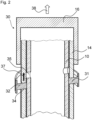
- Figure 2 shows an assembly 30 for a drug delivery device, for example for a drug delivery device 1 as shown in Figure 1 .
- the assembly may also be used in an alternative drug delivery device.
- the assembly may also be used in a variable dose device.
- the assembly 30 comprises a piston rod 10 and a snap feature 31.
- the piston rod 10 is configured as a lead screw.
- the assembly 30 comprises an actuator 16.
- the actuator 16 is configured as a button.
- the assembly 30 further comprises a drive member 14.
- the drive member 14 is configured as a drive sleeve.
- the actuator 16 may be fixedly coupled to the drive member 14, in particular to a proximal end of the drive member 14.
- the drive member 14 and the piston rod 10 are plotted cropped at both ends, since in reality, the drive member and the piston rod farther extend in an axial direction.
- the actuator 16 is schematically attached to one cropped end of the drive member 14, in particular to the proximal cropped end of the drive member 14. In reality, the actuator is attached to the proximal end of the drive member 14, as shown in Figure 1 .
- the dimensions of Figures 2 and 3 may not be true to original, they only serve to exemplify the function of the assembly 30.
- the assembly 30 is shown in a state before the assembly 30 is locked by the snap feature 31.
- the snap feature 31 may be preloaded due to the presence of the piston rod 10.
- the snap feature 31 may be deflected in a radial outward direction.
- the actuator 16 is configured to be operated in order to dispense a dose of medication.
- the actuator 16 may be pushed in a distal direction in order to dispense a dose.
- the drive member 14 may also be moved in a distal direction during the dispensing of a dose.
- the actuator 16 may be moved in a proximal direction, as indicated by arrow 38.
- the actuator 16, and thereby the drive member 14 may perform an axial and non-rotational movement in a proximal direction.
- the actuator 16 and the drive member 14 may perform a combined axial and rotational movement in a proximal direction.
- the actuator 16 and the drive member 14 may perform a purely rotational movement.
- the drive member 14 is configured to drive the piston rod 10 in a distal direction in order to dispense a dose.
- the assembly may be configured for use in a drug delivery device which may be a variable dose device such that a user can select the size of a dose.
- the assembly may be configured for use in a drug delivery device which may be a fixed dose device.
- the drug delivery device may be configured for multiple dose applications.
- the snap feature 31 comprises the shape of a ring.
- the snap feature 31 may be a resilient member. In one embodiment, a segment of the ring may be cut out in order to increase the flexibility of the ring. Alternatively, the ring may be closed.
- the snap feature is arranged concentrically around the drive member 14 and concentrically around the piston rod 10.
- the snap feature 31 is permanently engaged with the drive member 14. In particular, the snap feature 31 is rotationally and axially fixed with respect to the drive member 14.
- the drive member 14 comprises at least one, in particular two recesses 34, wherein the snap feature 31 is engaged with the recesses 34.
- the snap feature 31 comprises protrusions 32, which are permanently engaged with the recesses 34.
- the recesses 34 are configured as holes, which extend through the drive member 14. In particular, the holes extend in a radial direction with respect to a main axis of the device.
- the recesses 34 are oppositely arranged.
- the snap feature 31 may be configured to lock the assembly 30 of the drug delivery device such that the setting or the dispensing of a dose may be inhibited after a last dose of medication has been delivered from the drug delivery device.
- the snap feature 31 may engage with the piston rod 10 after a setting movement of the drive member 14.
- the snap feature 31 may be configured to lock the drive member 14 and the piston rod 10 with respect to each other such that no relative movement is possible between the drive member 14 and the piston rod 10.
- the snap feature 31 may be configured to engage with the piston rod 10 when the piston rod 10 and the drive member 14 are in a predetermined position with respect to each other.
- the piston rod 10 comprises at least one, in particular two recesses 35, wherein the protrusions 32 of the snap feature 31 may engage with the recesses 35 of the piston rod 10 when the piston rod 10 and the drive member 14 are in a predetermined position with respect to each other.
- the snap feature 31 may engage with the piston rod 10 when the recesses 35 of the piston rod 10 are aligned to the recesses 34 of the drive member.
- the snap feature 31 may snap into the recesses 35 of the piston rod 10.
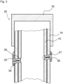
- Figure 3 shows the assembly 30 in a state where the snap feature 31 locks the assembly 30.
- the snap feature 31 may relax.
- the snap feature may deflect in a radial inward direction.
- the protrusions 32 of the snap feature 31 are engaged with the recesses 35 of the piston rod 10. Thereby, a relative movement between the drive member 14 and the piston rod 10 is inhibited.
- the snap feature 31 may be configured to allow a last setting movement of the actuator 16 after a last dose has been delivered, but to inhibit a subsequent dispense movement. According to a further embodiment, the snap feature 31 is configured to inhibit a setting movement of the actuator 16 after a last dose has been delivered.
- the assembly 30 may be used in a device wherein the drive member 14 may be moved along the piston rod 10 in a proximal direction during the setting of a dose, as indicated by arrow 37 in Figure 2 .
- a device is shown in Figure 1 .
- the drive member 14 may be configured to perform an axial, non-rotational movement.
- the drive member 14 may be rotationally fixed with respect to a housing (not shown) of the assembly 30.
- the piston rod 10 may be axially and rotationally fixed during the setting of a dose.
- the piston rod 10 may be moved in a distal direction by the drive member 14 when a user operates the actuator 16.
- the piston rod 10 may perform a combined axial and rotational movement during the dispensing of a dose.
- a fixed dose device is described for example in document WO 2008/058665 A1 .
- the piston rod 10 When a user tries to operate the actuator 16 after a last setting movement of the drive member 14, the piston rod 10 tries to rotate with respect to the drive member 14. Yet, such a rotational movement of the piston rod 10 is inhibited, since the piston rod 10 and the drive member 14 are locked with respect to each other. Consequently, the actuator 16 may not be operated by a user, and a dispense movement of the drive member 14 and the piston rod 10 is inhibited. Thereby, a user may recognize that the device is empty. Furthermore, the actuator 16 may permanently protrude from the device, which gives an additional, visible indication to a user that the device is empty.
- the drive member 14 may be rotated along the piston rod 10 in a proximal direction during the setting of a dose, while the piston rod 10 may be fixed with respect to a housing (not shown) of the drug delivery device.
- the piston rod 10 and the drive member 14 may be in a threaded engagement.
- the snap feature 31 may engage with the piston rod 10 and thereby lock the piston rod 10 and the drive member 14 with respect to each other.
- Figure 3 shows the assembly 30 with the snap feature 31 being in engagement with the piston rod 10.
- the actuator 16 may be pushed in a distal direction by a user.
- the drive member 14 and the piston rod 10 may be both moved in a distal direction.
- the drive member 14 and the piston rod 10 perform an axial, non-rotational movement during the dispensing of a dose.
- a last dose may be delivered from the drug delivery device.
- a subsequent setting of a dose is inhibited by means of the snap feature 31, since the drive member 14 cannot be rotated with respect to the piston rod 10 anymore. Thereby, a user may recognize that the device is empty.
Description
- The present disclosure relates to an assembly for a drug delivery device.
- A drug delivery device and an assembly for a drug delivery device are described for example in documents
WO 2008/058665 A1 andWO 2012/017036 A1 . - It is an object of the present invention to provide an assembly for a drug delivery device having improved properties, according to claim 1.
- An assembly for a drug delivery device is provided, wherein the assembly comprises an actuator which is configured to perform a setting movement in order to set a dose and which is configured to perform a dispense movement in order to dispense a dose. The assembly further comprises a piston rod which is configured to be moved in a distal direction in order to dispense a dose, and a snap feature which is configured to snap into engagement with the piston rod. The snap feature is configured to inhibit a dispense movement of the actuator when a maximum amount of medication has been delivered. The maximum amount of medication may be for example the amount of medication available in a cartridge.
- An advantage of a snap feature which is configured to snap into engagement with the piston rod is that the snap feature may permanently lock the assembly. When the assembly is locked, a movement of any component of the assembly may be inhibited.
- According to the invention, the snap feature is configured as a resilient member. In particular, the snap feature may comprise the shape of a ring. The snap feature may be arranged concentrically around the piston rod. In particular, the snap feature may be in contact with the piston rod throughout the use of the drug delivery device, i.e. also when it is not engaged with the piston rod. In particular, the snap feature may comprise at least one protrusion which may be in contact with the piston rod. The at least one protrusion may be arranged at an inner surface of the snap feature. For example, the snap feature may comprise two protrusions, which may be oppositely arranged. According to one embodiment, the snap feature is preloaded due to an interaction with the piston rod. In particular, the snap feature may be deflected in a radial outward direction due to the presence of the piston rod when the snap feature is not engaged with the piston rod.
- According to the invention, the snap feature is preloaded before snapping into engagement with the piston rod. In particular, the snap feature may be preloaded throughout the use of the drug delivery device. When snapping into engagement with the piston rod, the snap feature is enabled to relax. In particular, the snap feature may deflect in a radial inward direction, thereby engaging with the piston rod. In particular, the at least one protrusion of the snap feature may engage with the piston rod. When the snap feature is in engagement with the piston rod, the snap feature may still be slightly preloaded or it may be in an undeflected state.
- According to one embodiment the snap feature is configured to inhibit a dispense movement of the actuator after a last setting movement when a maximum amount of medication has been delivered. According to a further embodiment, the snap feature is configured to inhibit a setting movement of the actuator after a last dispense movement when a maximum amount of medication has been delivered.
- The setting movement of the actuator may be a translational movement in a proximal direction. For example, the setting movement may be an axial, non-rotational movement. Alternatively, the setting movement may be a combined axial and rotational movement. Alternatively, the setting movement may be a purely rotational movement. The dispense movement of the actuator may be a movement in a distal direction, for example a purely axial movement. In particular, the actuator may be pushed in a distal direction by a user in order to dispense a dose. The actuator may be configured as a button.
- The term "proximal direction" may describe a direction away from a dispensing end of the device. Analogously, the proximal end may be an end which is furthest away from a dispensing end. The term "distal direction" may describe a direction towards a dispensing end of the device.
- According to one embodiment, the snap feature is configured to snap into engagement with the piston rod after a last setting movement of the actuator. Alternatively, the snap feature may be configured to snap into engagement with the piston rod after a last dispense movement.
- According to the invention, the piston rod comprises at least one recess, wherein the snap feature is configured to engage with the recess. The at least one recess of the piston rod may be configured as a hole. The recess may extend in a direction which is perpendicular to a longitudinal axis of the device. According to one embodiment, the recess may extend through the piston rod. As an example, the piston rod may comprise two recesses, which may be oppositely arranged. The snap feature may be configured such that the at least one protrusion of the snap feature may engage into the at least one recess of the piston rod, in particular after a last setting or a last dispense movement of the actuator.
- According to one embodiment, the snap feature is configured to produce an audible click when snapping into engagement with the piston rod. The audible click may indicate to a user that a maximum amount of medication has been delivered. Alternatively, the audible click may indicate to a user that a last dose is ready to be delivered.
- According to the invention, the assembly comprises a drive member which is configured to drive the piston rod towards a distal end of the device in order to deliver a dose of medication. The drive member may be configured as a drive sleeve. The drive member may be arranged concentrically around the piston rod. In particular, the drive member may be coupled with the piston rod, for example by means of a thread. The drive member comprises at least one recess, wherein the snap feature is permanently engaged with the at least one recess of the drive member. In particular, the at least one protrusion of the snap feature is permanently engaged with the at least one recess of the drive member. The at least one recess may be configured as a hole. The at least one recess may extend through the drive member in a radial direction towards a longitudinal axis of the device. For example, the drive member may comprise two recesses, which may be oppositely arranged. According to one embodiment, the snap feature is arranged concentrically around the drive member.
- According to one embodiment, the snap feature is rotationally and axially fixed with respect to the drive member. In particular, the snap feature may be fixed with respect to the drive member by means of the at least one protrusion of the snap feature being engaged with the at least one recess of the drive member.
- The drive member may be fixedly coupled to the actuator. For example, the drive member and the actuator are manufactured as one part. In particular, a movement of the actuator may cause a movement of the drive member. Since the drive member and the actuator may be fixedly coupled to each other, the movement of the drive member may correspond to the movement of the actuator.
- During the setting of a dose, the drive member may be moved relative to the piston rod. In particular, the drive member may be moved along the piston rod in a proximal direction. For example, the drive member may perform an axial, non-rotational movement during the setting of a dose. Alternatively, the drive member may perform a combined axial and rotational movement. In particular, the drive member may be rotated along the piston rod. Alternatively the drive member may perform a purely rotational movement with respect to the piston rod. When the snap feature has engaged the piston rod, a relative movement between the drive member and the piston rod may be inhibited. Thereby, a further setting movement may be inhibited.
- According to an embodiment, a further dispense movement may be inhibited when the snap feature has engaged with the piston rod. In particular, a further dispense movement may be inhibited by the snap feature in case that the drive member and the piston rod are configured to be moved relative to each other during the dispense movement Alternatively, a further dispense movement may be enabled when the snap feature has engaged with the piston rod. In particular, a further dispense movement may be enabled when the snap feature has engaged with the piston rod in case that the drive member and the piston rod are configured to be fixed with respect to each other during a dispense movement. After the last dispense movement, a further setting movement may be inhibited by the snap feature. For example, the snap feature may snap into engagement with the piston rod when the drive member is in a most proximal position with respect to the piston rod. For example, the snap feature may snap into engagement with the piston rod at the end of a setting movement.
- During the dispensing of a dose, the piston rod and the drive member may be fixed with respect to each other. In particular, there may be no relative movement between the piston rod and the drive member. In particular, the piston rod and the drive member may be moved together in a distal direction. In an alternative embodiment, the piston rod and the drive member may move relative to each other during the dispense operation. In particular, the piston rod may rotate and axially move with respect to the drive member during the dispensing of a dose. In particular, a further dispense movement may be inhibited when the snap feature has engaged with the piston rod. Alternatively, a further dispense movement may be enabled when the snap feature has engaged with the piston rod.
- According to one embodiment, the drive member and the piston rod are locked with respect to each other when the snap feature is engaged with the piston rod. When the drive member and the piston rod are locked with respect to each other, any relative movement between the drive member and the piston rod is inhibited.
- The snap feature may snap into engagement with the piston rod when the piston rod and the drive member are in a predetermined position with respect to each other. In particular, the snap feature may be engaged with the piston rod when the at least one recess of the drive member is aligned with the at least one recess of the piston rod. In this state, the snap feature may be enabled to relax. In particular, the snap feature may be enabled to deflect in a radial inward direction. In particular, the at least one protrusion of the snap feature may further move through the at least one recess of the drive member and engage the at least one recess of the piston rod.
- According to one embodiment, a last setting movement is enabled and a dispense movement is inhibited, after the snap feature has engaged with the piston rod. Alternatively, a last dispense movement is enabled and a further setting movement is inhibited after the snap feature has engaged with the piston rod. Alternatively, a setting movement and a dispense movement are inhibited after the snap feature has engaged with the piston rod.
- For example, when the snap feature has engaged with the piston rod after a last setting movement, a relative movement between the drive member and the piston rod may be inhibited. Thereby, a movement in a distal direction of the drive member and the piston rod may be inhibited in the case that a dispense operation requires a relative movement of the drive member and the piston rod. Thereby, the device may be locked. In particular, no further setting or dispense movement may be possible. In this state, the actuator may protrude from a housing of the assembly. Thereby, an indication may be given to a user that the device is empty.
- According to a further example, when the snap feature has engaged with the piston rod after a last setting movement, a distal movement of the drive member and the piston rod may be enabled. In particular, a distal movement of the drive member and the piston rod may be enabled in the case that a dispense operation does not involve a relative movement between the drive member and the piston rod. In particular, an axial, non-rotational movement of the drive member and the piston rod may be enabled. Thereby, a last dose may be delivered. A further setting movement may be inhibited after the dispensing of the last dose, since the drive member may not be rotated along the piston rod in a proximal direction.
- According to a further embodiment, the snap feature may engage with the piston rod after a last dispense movement. In particular, the snap feature may engage with the piston rod in the case that the drive member and the piston rod are moved relative to each other during the dispensing of a dose. For example, the piston rod may be moved in a proximal direction with respect to the drive member. In particular, the piston rod may rotate and axially move in a proximal direction with respect to the drive member. Due to the snap feature engaging with the piston rod, the assembly may be locked after a dispense movement. In particular, a further setting movement and a further dispense movement may be inhibited.
- Furthermore, a drug delivery device is provided, the drug delivery device comprising an assembly which is configured as previously described. In particular, the drug delivery device may comprise a snap feature which is configured to snap into engagement with the piston rod, wherein the snap feature is configured to inhibit a dispense movement of the actuator and/or a setting movement after a last dispense movement when a maximum amount of medication has been delivered.
- The drug delivery device may be an injection device. The drug delivery device may be a pen-type device. The drug delivery device may be a fixed dose device such that the amount of medication which is delivered during one dispense operation is predetermined. In particular, a user may not be enabled to vary the size of the dose. Alternatively, the drug delivery device may be a variable dose device, such that the amount of medication which is delivered during one dispense operation may be selected by a user. The drug delivery device may be configured for multiple dose applications. The medication may be delivered to a user by means of a needle. The device may be delivered to a user in a fully assembled condition ready for use. The drug delivery device may be a disposable device. The term "disposable" means that the drug delivery device cannot be reused after an available amount of medication has been delivered from the drug delivery device. The drug delivery device may be configured to deliver a liquid medication. The medication may be, for example, insulin.
- The term "medication", as used herein, preferably means a pharmaceutical formulation containing at least one pharmaceutically active compound,
- wherein in one embodiment the pharmaceutically active compound has a molecular weight up to 1500 Da and/or is a peptide, a proteine, a polysaccharide, a vaccine, a DNA, a RNA, an enzyme, an antibody or a fragment thereof, a hormone or an oligonucleotide, or a mixture of the above-mentioned pharmaceutically active compound,
- wherein in a further embodiment the pharmaceutically active compound is useful for the treatment and/or prophylaxis of diabetes mellitus or complications associated with diabetes mellitus such as diabetic retinopathy, thromboembolism disorders such as deep vein or pulmonary thromboembolism, acute coronary syndrome (ACS), angina, myocardial infarction, cancer, macular degeneration, inflammation, hay fever, atherosclerosis and/or rheumatoid arthritis,
- wherein in a further embodiment the pharmaceutically active compound comprises at least one peptide for the treatment and/or prophylaxis of diabetes mellitus or complications associated with diabetes mellitus such as diabetic retinopathy,
- wherein in a further embodiment the pharmaceutically active compound comprises at least one human insulin or a human insulin analogue or derivative, glucagon-like peptide (GLP-1) or an analogue or derivative thereof, or exendin-3 or exendin-4 or an analogue or derivative of exendin-3 or exendin-4.
- Insulin analogues are for example Gly(A21), Arg(B31), Arg(B32) human insulin; Lys(B3), Glu(B29) human insulin; Lys(B28), Pro(B29) human insulin; Asp(B28) human insulin; human insulin, wherein proline in position B28 is replaced by Asp, Lys, Leu, Val or Ala and wherein in position B29 Lys may be replaced by Pro; Ala(B26) human insulin; Des(B28-B30) human insulin; Des(B27) human insulin and Des(B30) human insulin.
- Insulin derivates are for example B29-N-myristoyl-des(B30) human insulin; B29-N-palmitoyl-des(B30) human insulin; B29-N-myristoyl human insulin; B29-N-palmitoyl human insulin; B28-N-myristoyl LysB28ProB29 human insulin; B28-N-palmitoyl-LysB28ProB29 human insulin; B30-N-myristoyl-ThrB29LysB30 human insulin; B30-N-palmitoyl- ThrB29LysB30 human insulin; B29-N-(N-palmitoyl-Y-glutamyl)-des(B30) human insulin; B29-N-(N-lithocholyl-Y-glutamyl)-des(B30) human insulin; B29-N-(ω-carboxyheptadecanoyl)-des(B30) human insulin and B29-N-(ω-carboxyheptadecanoyl) human insulin.
- Exendin-4 for example means Exendin-4(1-39), a peptide of the sequence H-His-Gly-Glu-Gly-Thr-Phe-Thr-Ser-Asp-Leu-Ser-Lys-Gln-Met-Glu-Glu-Glu-Ala-Val-Arg-Leu-Phe-Ile-Glu-Trp-Leu-Lys-Asn-Gly-Gly-Pro-Ser-Ser-Gly-Ala-Pro-Pro-Pro-Ser-NH2.
- Exendin-4 derivatives are for example selected from the following list of compounds:
- H-(Lys)4-des Pro36, des Pro37 Exendin-4(1-39)-NH2,
- H-(Lys)5-des Pro36, des Pro37 Exendin-4(1-39)-NH2,
- des Pro36 Exendin-4(1-39),
- des Pro36 [Asp28] Exendin-4(1-39),
- des Pro36 [IsoAsp28] Exendin-4(1-39),
- des Pro36 [Met(O)14, Asp28] Exendin-4(1-39),
- des Pro36 [Met(O)14, IsoAsp28] Exendin-4(1-39),
- des Pro36 [Trp(O2)25, Asp28] Exendin-4(1-39),
- des Pro36 [Trp(O2)25, IsoAsp28] Exendin-4(1-39),
- des Pro36 [Met(O)14 Trp(O2)25, Asp28] Exendin-4(1-39),
- des Pro36 [Met(O)14 Trp(O2)25, IsoAsp28] Exendin-4(1-39); or
- des Pro36 [Asp28] Exendin-4(1-39),
- des Pro36 [IsoAsp28] Exendin-4(1-39),
- des Pro36 [Met(O)14, Asp28] Exendin-4(1-39),
- des Pro36 [Met(O)14, IsoAsp28] Exendin-4(1-39),
- des Pro36 [Trp(O2)25, Asp28] Exendin-4(1-39),
- des Pro36 [Trp(O2)25, IsoAsp28] Exendin-4(1-39),
- des Pro36 [Met(O)14 Trp(O2)25, Asp28] Exendin-4(1-39),
- des Pro36 [Met(O)14 Trp(O2)25, IsoAsp28] Exendin-4(1-39),
- wherein the group -Lys6-NH2 may be bound to the C-terminus of the Exendin-4 derivative;
- or an Exendin-4 derivative of the sequence
- des Pro36 Exendin-4(1-39)-Lys6-NH2 (AVE0010),
- H-(Lys)6-des Pro36 [Asp28] Exendin-4(1-39)-Lys6-NH2,
- des Asp28 Pro36, Pro37, Pro38Exendin-4(1-39)-NH2,
- H-(Lys)6-des Pro36, Pro38 [Asp28] Exendin-4(1-39)-NH2,
- H-Asn-(Glu)5des Pro36, Pro37, Pro38 [Asp28] Exendin-4(1-39)-NH2,
- des Pro36, Pro37, Pro38 [Asp28] Exendin-4(1-39)-(Lys)6-NH2,
- H-(Lys)6-des Pro36, Pro37, Pro38 [Asp28] Exendin-4(1-39)-(Lys)6-NH2,
- H-Asn-(Glu)5-des Pro36, Pro37, Pro38 [Asp28] Exendin-4(1-39)-(Lys)6-NH2,
- H-(Lys)6-des Pro36 [Trp(O2)25, Asp28] Exendin-4(1-39)-Lys6-NH2,
- H-des Asp28 Pro36, Pro37, Pro38 [Trp(O2)25] Exendin-4(1-39)-NH2,
- H-(Lys)6-des Pro36, Pro37, Pro38 [Trp(O2)25, Asp28] Exendin-4(1-39)-NH2,
- H-Asn-(Glu)5-des Pro36, Pro37, Pro38 [Trp(O2)25, Asp28] Exendin-4(1-39)-NH2,
- des Pro36, Pro37, Pro38 [Trp(O2)25, Asp28] Exendin-4(1-39)-(Lys)6-NH2,
- H-(Lys)6-des Pro36, Pro37, Pro38 [Trp(O2)25, Asp28] Exendin-4(1-39)-(Lys)6-NH2,
- H-Asn-(Glu)5-des Pro36, Pro37, Pro38 [Trp(O2)25, Asp28] Exendin-4(1-39)-(Lys)6-NH2,
- H-(Lys)6-des Pro36 [Met(O)14, Asp28] Exendin-4(1-39)-Lys6-NH2,
- des Met(O)14 Asp28 Pro36, Pro37, Pro38 Exendin-4(1-39)-NH2,
- H-(Lys)6-desPro36, Pro37, Pro38 [Met(O)14, Asp28] Exendin-4(1-39)-NH2,
- H-Asn-(Glu)5-des Pro36, Pro37, Pro38 [Met(O)14, Asp28] Exendin-4(1-39)-NH2,
- des Pro36, Pro37, Pro38 [Met(O)14, Asp28] Exendin-4(1-39)-(Lys)6-NH2,
- H-(Lys)6-des Pro36, Pro37, Pro38 [Met(O)14, Asp28] Exendin-4(1-39)-(Lys)6-NH2,
- H-Asn-(Glu)5 des Pro36, Pro37, Pro38 [Met(O)14, Asp28] Exendin-4(1-39)-(Lys)6-NH2,
- H-Lys6-des Pro36 [Met(O)14, Trp(O2)25, Asp28] Exendin-4(1-39)-Lys6-NH2,
- H-des Asp28 Pro36, Pro37, Pro38 [Met(O)14, Trp(O2)25] Exendin-4(1-39)-NH2,
- H-(Lys)6-des Pro36, Pro37, Pro38 [Met(O)14, Asp28] Exendin-4(1-39)-NH2,
- H-Asn-(Glu)5-des Pro36, Pro37, Pro38 [Met(O)14, Trp(O2)25, Asp28] Exendin-4(1-39)-NH2,
- des Pro36, Pro37, Pro38 [Met(O)14, Trp(O2)25, Asp28] Exendin-4(1-39)-(Lys)6-NH2,
- H-(Lys)6-des Pro36, Pro37, Pro38 [Met(O)14, Trp(O2)25, Asp28] Exendin-4(S1-39)-(Lys)6-NH2,
- H-Asn-(Glu)5-des Pro36, Pro37, Pro38 [Met(O)14, Trp(O2)25, Asp28] Exendin-4(1-39)-(Lys)6-NH2;
- or a pharmaceutically acceptable salt or solvate of any one of the afore-mentioned Exendin-4 derivative.
- Hormones are for example hypophysis hormones or hypothalamus hormones or regulatory active peptides and their antagonists as listed in Rote Liste, ed. 2008, Chapter 50, such as Gonadotropine (Follitropin, Lutropin, Choriongonadotropin, Menotropin), Somatropine (Somatropin), Desmopressin, Terlipressin, Gonadorelin, Triptorelin, Leuprorelin, Buserelin, Nafarelin, Goserelin.
- A polysaccharide is for example a glucosaminoglycane, a hyaluronic acid, a heparin, a low molecular weight heparin or an ultra low molecular weight heparin or a derivative thereof, or a sulphated, e.g. a poly-sulphated form of the above-mentioned polysaccharides, and/or a pharmaceutically acceptable salt thereof. An example of a pharmaceutically acceptable salt of a poly-sulphated low molecular weight heparin is enoxaparin sodium.
- Antibodies are globular plasma proteins (-150 kDa) that are also known as immunoglobulins which share a basic structure. As they have sugar chains added to amino acid residues, they are glycoproteins. The basic functional unit of each antibody is an immunoglobulin (Ig) monomer (containing only one Ig unit); secreted antibodies can also be dimeric with two Ig units as with IgA, tetrameric with four Ig units like teleost fish IgM, or pentameric with five Ig units, like mammalian IgM.
- The Ig monomer is a "Y"-shaped molecule that consists of four polypeptide chains; two identical heavy chains and two identical light chains connected by disulfide bonds between cysteine residues. Each heavy chain is about 440 amino acids long; each light chain is about 220 amino acids long. Heavy and light chains each contain intrachain disulfide bonds which stabilize their folding. Each chain is composed of structural domains called Ig domains. These domains contain about 70-110 amino acids and are classified into different categories (for example, variable or V, and constant or C) according to their size and function. They have a characteristic immunoglobulin fold in which two β sheets create a "sandwich" shape, held together by interactions between conserved cysteines and other charged amino acids.
- There are five types of mammalian Ig heavy chain denoted by α, δ, ε, γ, and µ. The type of heavy chain present defines the isotype of antibody; these chains are found in IgA, IgD, IgE, IgG, and IgM antibodies, respectively.
- Distinct heavy chains differ in size and composition; α and γ contain approximately 450 amino acids and δ approximately 500 amino acids, while µ and ε have approximately 550 amino acids. Each heavy chain has two regions, the constant region (CH) and the variable region (VH). In one species, the constant region is essentially identical in all antibodies of the same isotype, but differs in antibodies of different isotypes. Heavy chains γ, α and δ have a constant region composed of three tandem Ig domains, and a hinge region for added flexibility; heavy chains µ and ε have a constant region composed of four immunoglobulin domains. The variable region of the heavy chain differs in antibodies produced by different B cells, but is the same for all antibodies produced by a single B cell or B cell clone. The variable region of each heavy chain is approximately 110 amino acids long and is composed of a single Ig domain.
- In mammals, there are two types of immunoglobulin light chain denoted by λ and κ. A light chain has two successive domains: one constant domain (CL) and one variable domain (VL). The approximate length of a light chain is 211 to 217 amino acids. Each antibody contains two light chains that are always identical; only one type of light chain, κ or λ, is present per antibody in mammals.
- Although the general structure of all antibodies is very similar, the unique property of a given antibody is determined by the variable (V) regions, as detailed above. More specifically, variable loops, three each the light (VL) and three on the heavy (VH) chain, are responsible for binding to the antigen, i.e. for its antigen specificity. These loops are referred to as the Complementarity Determining Regions (CDRs). Because CDRs from both VH and VL domains contribute to the antigen-binding site, it is the combination of the heavy and the light chains, and not either alone, that determines the final antigen specificity.
- An "antibody fragment" contains at least one antigen binding fragment as defined above, and exhibits essentially the same function and specificity as the complete antibody of which the fragment is derived from. Limited proteolytic digestion with papain cleaves the Ig prototype into three fragments. Two identical amino terminal fragments, each containing one entire L chain and about half an H chain, are the antigen binding fragments (Fab). The third fragment, similar in size but containing the carboxyl terminal half of both heavy chains with their interchain disulfide bond, is the crystalizable fragment (Fc). The Fc contains carbohydrates, complement-binding, and FcR-binding sites. Limited pepsin digestion yields a single F(ab')2 fragment containing both Fab pieces and the hinge region, including the H-H interchain disulfide bond. F(ab')2 is divalent for antigen binding. The disulfide bond of F(ab')2 may be cleaved in order to obtain Fab'. Moreover, the variable regions of the heavy and light chains can be fused together to form a single chain variable fragment (scFv).
- Pharmaceutically acceptable salts are for example acid addition salts and basic salts. Acid addition salts are e.g. HCl or HBr salts. Basic salts are e.g. salts having a cation selected from alkali or alkaline, e.g. Na+, or K+, or Ca2+, or an ammonium ion N+(R1)(R2)(R3)(R4), wherein R1 to R4 independently of each other mean: hydrogen, an optionally substituted C1-C6-alkyl group, an optionally substituted C2-C6-alkenyl group, an optionally substituted C6-C10-aryl group, or an optionally substituted C6-C10-heteroaryl group. Further examples of pharmaceutically acceptable salts are described in "Remington's Pharmaceutical Sciences" 17. ed. Alfonso R. Gennaro (Ed.), Mark Publishing Company, Easton, Pa., U.S.A., 1985 and in Encyclopedia of Pharmaceutical Technology.
- Pharmaceutically acceptable solvates are for example hydrates.
- Further features, refinements and expediencies become apparent from the following description of the exemplary embodiments in connection with the figures.
-
Figure 1 shows a drug delivery device in a sectional view, -
Figure 2 shows an assembly for a drug delivery device, -
Figure 3 shows the assembly offigure 1 in a different state. -
Figure 1 shows a sectional view of a drug delivery device 1. The drug delivery device 1 comprises acartridge retaining part 2, and amain housing part 3. The proximal end of thecartridge retaining part 2 and the distal end of themain housing 3 are secured together by any suitable means known to the person skilled in the art. In the illustrated embodiment, thecartridge retaining part 2 is secured within the distal end of themain housing part 3. - A
cartridge 4 from which a number of doses of a medicinal product may be dispensed is provided in thecartridge retaining part 2. Apiston 5 is retained in the proximal end of thecartridge 4. - A
removable cap 22 is releasably retained over the distal end of thecartridge retaining part 2. Theremovable cap 22 is optionally provided with one or more window apertures through which the position of thepiston 5 within thecartridge 4 can be viewed. - The distal end of the
cartridge retaining part 2 in the illustrated embodiment, is provided with a distal threadedregion 6 designed for the attachment of a suitable needle assembly (not shown) to enable medicament to be dispensed from thecartridge 4. - In the illustrated embodiment, the
main housing part 3 is provided with aninternal housing 7. Theinternal housing 7 is secured against rotational and/or axial movement with respect to themain housing part 3. Theinternal housing 7 is provided with a threadedcircular opening 8 extending through the distal end of theinternal housing 7. In the illustrated embodiment the threadedcircular opening 8 comprises a series of part threads rather than a complete thread. Alternatively, theinternal housing 7 may be formed integrally with themain housing part 3. Additionally, theinternal housing 7 is provided with a plurality of guide slots and pawl means. - A
first thread 9 is formed at the distal end of thepiston rod 10. Thepiston rod 10 is of generally circular cross-section. Thefirst thread 9 of thepiston rod 10 extends through and is threadedly engaged with the threadedcircular opening 8 of theinternal housing 7. Apressure foot 11 is located at the distal end of thepiston rod 10. Thepressure foot 11 is disposed to abut the proximal face of thepiston 5. Asecond thread 12 is formed at the proximal end of thepiston rod 10. In the illustrated embodiment thesecond thread 12 comprises a series of part threads, rather than a complete thread, formed onflexible arms 13 of thepiston rod 10. - The
first thread 9 and thesecond thread 12 are oppositely disposed. - In the illustrated embodiment the
first thread 9 is provided with a plurality of features (not shown) that cooperate with the part threads of the threadedcircular opening 8 to prevent movement of thepiston rod 10 in the proximal direction during setting of the dose. - A
drive member 14 extends about thepiston rod 10. Thedrive member 14 is configured as a drive sleeve. Thedrive member 14 comprises a threadedpart 15 of a generally cylindrical cross-section. Anactuator 16 is located at a proximal end of thedrive member 14. The threadedpart 15 and theactuator 16 are secured to each other to prevent rotational and/or axial movement there between. Alternatively, thedrive member 14 may be a unitary component consisting of an integrated threadedpart 15 andactuator 16. - In the illustrated embodiment, the threaded
part 15 is provided with a longitudinally extendinghelical thread 17 formed on the internal cylindrical surface. The flank of the proximal side of thehelical thread 17 is designed to maintain contact with thesecond thread 12 of thepiston rod 10 when dispensing a dose, whilst the flank of the distal side of thehelical thread 17 is designed to allow thesecond thread 12 of thepiston rod 10 to disengage when setting a dose. In this way thehelical thread 17 of the threadedpart 15 is releasably engaged with thesecond thread 12 of thepiston rod 10. - The
drive member 14 has a plurality of features formed on the external surface designed to move axially within the guide slots of theinternal housing 7. These guide slots define the extent of permissible axial movement of thedrive member 14 with respect to thehousing part 3. In the illustrated embodiment the guide slots also prevent rotational movement of thedrive member 14 relative to themain housing part 3. - The
actuator 16 has a plurality of grip surfaces 18 and a dispensingface 19. - To increase intuitiveness of the operation of the device, the
main housing part 3 may be provided with a window aperture through which graphical status indicators, provided on thedrive member 14, can be viewed. - Operation of the drug delivery device in accordance with the present invention will now be described.
- To set a dose a user grips the grip surfaces 18 of the
drive member 14. The user then pulls thedrive member 14 in a proximal direction away from themain housing part 3. - The
piston rod 10 is prevented from moving proximally by the part threads of the threadedcircular opening 8 of theinternal housing 7 interacting with thread features on thefirst thread 9 of thepiston rod 10 or by any other suitable means. As thedrive member 14 travels in the proximal direction relative to thepiston rod 10, thesecond thread 12 of thepiston rod 10 is displaced radially inwards by the flank of the distal side ofhelical thread 17 of thedrive member 14. - The proximal travel of the
drive member 14 is limited by the guide slots (not shown) of the internal housing 7 a distance corresponding to essentially one thread pitch of thehelical thread 17 of thedrive member 14. At the end of the travel of thedrive member 14, thesecond thread 12 of thepiston rod 10 engages with thehelical thread 17 under the action of theflexible arms 13 of thepiston rod 10. By this action thedrive member 14 is displaced a distance essentially equal to one pitch of thehelical thread 17 of thedrive member 14 in the proximal direction relative to thepiston rod 10. The action of thesecond thread 12 positively engaging thehelical thread 17 of thedrive member 14 under a force provided by theflexible arms 13 creates an audible and tactile feedback to the user to indicate that the dose has been set. Additionally, visual feedback regarding dose setting may be indicated by an optional graphical status indicator, provided on thedrive member 14, which can be viewed through an optional window aperture in themain housing part 3. - When the dose has been set, the user may then dispense this dose by depressing the dispensing
face 19 of theactuator 16. By this action thedrive member 14 is moved axially in the distal direction relative to themain housing part 3. As thesecond thread 12 of thepiston rod 10 is positively engaged with thehelical thread 17 of thedrive member 14 thepiston rod 10 is caused to rotate with respect to theinternal housing 7 by the axial movement of thedrive member 14 in the distal direction. As thepiston rod 10 rotates, thefirst thread 9 of thepiston rod 10 rotates within the threadedcircular opening 8 of theinternal housing 7 causing thepiston rod 10 to move axially in the distal direction with respect to theinternal housing 7. - The distal axial movement of the
piston rod 10 causes thepressure foot 11 to bear against thepiston 5 of thecartridge 4 causing a dose of medicament to be dispensed through an attached needle. - The distal travel of the
drive member 14 is limited by the guide slots (not shown) of theinternal housing 7. Thedrive member 14 is provided with a detent means (not shown) that is designed to interact with the pawl means (not shown) of theinternal housing 7. - Audible and tactile feedback to indicate that the dose has been dispensed is provided by the interaction of the detent of the
drive member 14 with the pawl means of theinternal housing 7. Additionally, visual feedback regarding dose dispensing may be indicated by an optional graphical status indicator, provided on thedrive member 14, which can be viewed through an optional window aperture in themain housing part 3. - Further doses may be delivered as required up to a pre-determined maximum number of doses.
-
Figure 2 shows anassembly 30 for a drug delivery device, for example for a drug delivery device 1 as shown inFigure 1 . However, the assembly may also be used in an alternative drug delivery device. For example, the assembly may also be used in a variable dose device. Theassembly 30 comprises apiston rod 10 and asnap feature 31. Thepiston rod 10 is configured as a lead screw. Furthermore, theassembly 30 comprises anactuator 16. Theactuator 16 is configured as a button. Theassembly 30 further comprises adrive member 14. Thedrive member 14 is configured as a drive sleeve. Theactuator 16 may be fixedly coupled to thedrive member 14, in particular to a proximal end of thedrive member 14. InFigures 2 and3 , thedrive member 14 and thepiston rod 10 are plotted cropped at both ends, since in reality, the drive member and the piston rod farther extend in an axial direction. Theactuator 16 is schematically attached to one cropped end of thedrive member 14, in particular to the proximal cropped end of thedrive member 14. In reality, the actuator is attached to the proximal end of thedrive member 14, as shown inFigure 1 . However, the dimensions ofFigures 2 and3 may not be true to original, they only serve to exemplify the function of theassembly 30. - In
Figure 2 , theassembly 30 is shown in a state before theassembly 30 is locked by thesnap feature 31. In this state, thesnap feature 31 may be preloaded due to the presence of thepiston rod 10. In particular, thesnap feature 31 may be deflected in a radial outward direction. - The
actuator 16 is configured to be operated in order to dispense a dose of medication. In particular, theactuator 16 may be pushed in a distal direction in order to dispense a dose. Thereby, thedrive member 14 may also be moved in a distal direction during the dispensing of a dose. In order to set a dose, theactuator 16 may be moved in a proximal direction, as indicated byarrow 38. For example, theactuator 16, and thereby thedrive member 14, may perform an axial and non-rotational movement in a proximal direction. Alternatively, theactuator 16 and thedrive member 14 may perform a combined axial and rotational movement in a proximal direction. Alternatively, theactuator 16 and thedrive member 14 may perform a purely rotational movement. Thedrive member 14 is configured to drive thepiston rod 10 in a distal direction in order to dispense a dose. - The assembly may be configured for use in a drug delivery device which may be a variable dose device such that a user can select the size of a dose. Alternatively, the assembly may be configured for use in a drug delivery device which may be a fixed dose device. The drug delivery device may be configured for multiple dose applications.
- The
snap feature 31 comprises the shape of a ring. Thesnap feature 31 may be a resilient member. In one embodiment, a segment of the ring may be cut out in order to increase the flexibility of the ring. Alternatively, the ring may be closed. The snap feature is arranged concentrically around thedrive member 14 and concentrically around thepiston rod 10. Thesnap feature 31 is permanently engaged with thedrive member 14. In particular, thesnap feature 31 is rotationally and axially fixed with respect to thedrive member 14. - The
drive member 14 comprises at least one, in particular tworecesses 34, wherein thesnap feature 31 is engaged with therecesses 34. In particular, thesnap feature 31 comprisesprotrusions 32, which are permanently engaged with therecesses 34. Therecesses 34 are configured as holes, which extend through thedrive member 14. In particular, the holes extend in a radial direction with respect to a main axis of the device. Therecesses 34 are oppositely arranged. - The
snap feature 31 may be configured to lock theassembly 30 of the drug delivery device such that the setting or the dispensing of a dose may be inhibited after a last dose of medication has been delivered from the drug delivery device. - The
snap feature 31 may engage with thepiston rod 10 after a setting movement of thedrive member 14. In particular, thesnap feature 31 may be configured to lock thedrive member 14 and thepiston rod 10 with respect to each other such that no relative movement is possible between thedrive member 14 and thepiston rod 10. In particular, thesnap feature 31 may be configured to engage with thepiston rod 10 when thepiston rod 10 and thedrive member 14 are in a predetermined position with respect to each other. - The
piston rod 10 comprises at least one, in particular tworecesses 35, wherein theprotrusions 32 of thesnap feature 31 may engage with therecesses 35 of thepiston rod 10 when thepiston rod 10 and thedrive member 14 are in a predetermined position with respect to each other. In particular, thesnap feature 31 may engage with thepiston rod 10 when therecesses 35 of thepiston rod 10 are aligned to therecesses 34 of the drive member. In particular, thesnap feature 31 may snap into therecesses 35 of thepiston rod 10. -
Figure 3 shows theassembly 30 in a state where thesnap feature 31 locks theassembly 30. In particular, when thedrive member 14 and thepiston rod 10 are in a predetermined position with respect to each other, therecesses 35 of the piston rod and therecesses 34 of thedrive member 14 are aligned with respect to each other. In this position, thesnap feature 31 may relax. In particular, the snap feature may deflect in a radial inward direction. In particular, theprotrusions 32 of thesnap feature 31 are engaged with therecesses 35 of thepiston rod 10. Thereby, a relative movement between thedrive member 14 and thepiston rod 10 is inhibited. - According to one embodiment, the
snap feature 31 may be configured to allow a last setting movement of theactuator 16 after a last dose has been delivered, but to inhibit a subsequent dispense movement. According to a further embodiment, thesnap feature 31 is configured to inhibit a setting movement of theactuator 16 after a last dose has been delivered. - According to one exemplary embodiment, the
assembly 30 may be used in a device wherein thedrive member 14 may be moved along thepiston rod 10 in a proximal direction during the setting of a dose, as indicated byarrow 37 inFigure 2 . Such a device is shown inFigure 1 . Thedrive member 14 may be configured to perform an axial, non-rotational movement. In particular, thedrive member 14 may be rotationally fixed with respect to a housing (not shown) of theassembly 30. Thepiston rod 10 may be axially and rotationally fixed during the setting of a dose. During the dispensing of a dose, thepiston rod 10 may be moved in a distal direction by thedrive member 14 when a user operates theactuator 16. In particular, thepiston rod 10 may perform a combined axial and rotational movement during the dispensing of a dose. A fixed dose device is described for example in documentWO 2008/058665 A1 . - When the device is empty, a last setting movement of the
drive member 14 may be allowed. When thedrive member 14 is moved in a proximal direction with respect to thepiston rod 10, therecesses 34 of thedrive member 14 may come to lie over therecess 35 of thepiston rod 10. In this state, thesnap feature 31 may engage with thepiston rod 10, as indicated by thearrows 36 inFigure 3 . Thereby, thepiston rod 10 and thedrive member 14 are locked with respect to each other. - When a user tries to operate the
actuator 16 after a last setting movement of thedrive member 14, thepiston rod 10 tries to rotate with respect to thedrive member 14. Yet, such a rotational movement of thepiston rod 10 is inhibited, since thepiston rod 10 and thedrive member 14 are locked with respect to each other. Consequently, theactuator 16 may not be operated by a user, and a dispense movement of thedrive member 14 and thepiston rod 10 is inhibited. Thereby, a user may recognize that the device is empty. Furthermore, theactuator 16 may permanently protrude from the device, which gives an additional, visible indication to a user that the device is empty. - According to a further exemplary embodiment, the
drive member 14 may be rotated along thepiston rod 10 in a proximal direction during the setting of a dose, while thepiston rod 10 may be fixed with respect to a housing (not shown) of the drug delivery device. In particular, thepiston rod 10 and thedrive member 14 may be in a threaded engagement. When a dose is set which is equal to an amount of medication left in a cartridge of the device, thesnap feature 31 may engage with thepiston rod 10 and thereby lock thepiston rod 10 and thedrive member 14 with respect to each other.Figure 3 shows theassembly 30 with thesnap feature 31 being in engagement with thepiston rod 10. - Subsequently, the
actuator 16 may be pushed in a distal direction by a user. Thereby, thedrive member 14 and thepiston rod 10 may be both moved in a distal direction. In particular, thedrive member 14 and thepiston rod 10 perform an axial, non-rotational movement during the dispensing of a dose. Thereby, a last dose may be delivered from the drug delivery device. - A subsequent setting of a dose is inhibited by means of the
snap feature 31, since thedrive member 14 cannot be rotated with respect to thepiston rod 10 anymore. Thereby, a user may recognize that the device is empty. -
- 1
- drug delivery device
- 2
- cartridge retaining part
- 3
- main housing part
- 4
- cartridge
- 5
- piston
- 6
- distal threaded region
- 7
- internal housing
- 8
- threaded circular opening
- 9
- first thread
- 10
- piston rod
- 11
- pressure foot
- 12
- second thread
- 13
- flexible arms
- 14
- drive member
- 15
- threaded part
- 16
- actuator
- 17
- helical thread
- 18
- grip surface
- 19
- dispensing face
- 22
- removable cap
- 30
- assembly
- 31
- snap feature
- 32
- protrusion
- 34
- recess
- 35
- recess
- 36
- arrow
- 37
- arrow
- 38
- arrow
Claims (13)
- An assembly for a drug delivery device, the assembly (30) comprising an actuator (16) which is configured to perform a setting movement in order to set a dose and which is configured to perform a dispense movement in order to dispense a dose, and a piston rod (10), which is configured to be moved in a distal direction in order to dispense a dose, and a snap feature (31) which is configured to snap into engagement with the piston rod (10), wherein the snap feature (31) is configured to inhibit a dispense movement of the actuator (16) when a maximum amount of medication has been delivered, and wherein the assembly comprises a drive member (14) which is configured to drive the piston rod (10) towards a distal end of the device in order to deliver a dose of medication, wherein the snap feature (31) is configured as a resilient member, wherein the snap feature (31) is preloaded before snapping into engagement with the piston rod (10), and wherein the snap feature (31) is enabled to relax when snapping into engagement with the piston rod (10) characterised in that the drive member comprises at least one first recess (34), wherein the snap feature (31) comprises at least one protrusion (32) which is permanently engaged with the first recess (34) of the drive member (14), wherein the piston rod (10) comprises at least one second recess (35), wherein the snap feature (31) is configured to engage with the second recess (35).
- The assembly according to claim 1, wherein the snap feature (31) is configured to inhibit the dispense movement of the actuator (16) after a last setting movement of the actuator (16) when the maximum amount of medication has been delivered.
- The assembly according to claim 2, wherein the snap feature (31) is configured to snap into engagement with the piston rod (10) after the last setting movement of the actuator (16) when the maximum amount of medication has been delivered.
- The assembly according to any of the previous claims, wherein the snap feature (31) is preloaded due to an interaction with the piston rod (10).
- The assembly according to any of the previous claims, wherein the snap feature (31) comprises the shape of a ring.
- The assembly according to any of the previous claims, wherein the snap feature (31) is arranged concentrically with respect to the piston rod (10).
- The assembly according to any of the previous claims, wherein the snap feature (31) is configured to engage with the at least one second recess (35) of the piston rod (10), when the at least one second recess (35) of the piston rod (10) and the at least one first recess (34) of the drive member (14) are aligned with respect to each other.
- The assembly according to any of the previous claims, wherein the snap feature (31) is rotationally and axially fixed with respect to the drive member (14).
- The assembly according to any of the previous claims, wherein the drive member (14) and the piston rod (10) are locked relative to each other when the snap feature (31) is engaged with the piston rod (10).
- The assembly according to any of the previous claims, wherein the snap feature (31) is arranged concentrically around the drive member (14).
- The assembly according to any of the previous claims, wherein the snap feature (31) is further configured to inhibit a setting movement of the actuator (16).
- A drug delivery device comprising the assembly (30) according to any of the previous claims.
- The drug delivery device according to claim 12, wherein the drug delivery device contains a drug.
Priority Applications (1)
| Application Number | Priority Date | Filing Date | Title |
|---|---|---|---|
| EP14702046.5A EP2950857B1 (en) | 2013-02-04 | 2014-02-03 | Assembly for a drug delivery device |
Applications Claiming Priority (3)
| Application Number | Priority Date | Filing Date | Title |
|---|---|---|---|
| EP13153796 | 2013-02-04 | ||
| EP14702046.5A EP2950857B1 (en) | 2013-02-04 | 2014-02-03 | Assembly for a drug delivery device |
| PCT/EP2014/051978 WO2014118357A1 (en) | 2013-02-04 | 2014-02-03 | Assembly for a drug delivery device |
Publications (2)
| Publication Number | Publication Date |
|---|---|
| EP2950857A1 EP2950857A1 (en) | 2015-12-09 |
| EP2950857B1 true EP2950857B1 (en) | 2023-06-07 |
Family
ID=47709935
Family Applications (1)
| Application Number | Title | Priority Date | Filing Date |
|---|---|---|---|
| EP14702046.5A Active EP2950857B1 (en) | 2013-02-04 | 2014-02-03 | Assembly for a drug delivery device |
Country Status (7)
| Country | Link |
|---|---|
| US (1) | US10314978B2 (en) |
| EP (1) | EP2950857B1 (en) |
| JP (1) | JP6333859B2 (en) |
| CN (1) | CN104955506B (en) |
| DK (1) | DK2950857T3 (en) |
| HK (1) | HK1211516A1 (en) |
| WO (1) | WO2014118357A1 (en) |
Families Citing this family (2)
| Publication number | Priority date | Publication date | Assignee | Title |
|---|---|---|---|---|
| US10525204B2 (en) * | 2013-11-22 | 2020-01-07 | Sanofi-Aventis Deutschland Gmbh | Drug delivery device |
| JP6352529B2 (en) * | 2015-04-03 | 2018-07-04 | 株式会社日立ハイテクノロジーズ | Light amount detection device, immunoassay device using the same, and charged particle beam device |
Family Cites Families (15)
| Publication number | Priority date | Publication date | Assignee | Title |
|---|---|---|---|---|
| US4850968A (en) * | 1987-07-27 | 1989-07-25 | Ar.Ma.S.R.L. | Self-blocking hypodermic syringe for once-only use, comprising a needle protection cap |
| US4932941A (en) * | 1988-03-14 | 1990-06-12 | Min Kyung M | Non-reusable disposable syringe |
| US5120314A (en) * | 1991-03-22 | 1992-06-09 | Greenwood Eugene C | Single use hypodermic syringe |
| WO2006089767A1 (en) * | 2005-02-28 | 2006-08-31 | Novo Nordisk A/S | Dose setting mechanism for an injection device capable of presetting a maximum dose |
| DE102006038101A1 (en) * | 2006-08-14 | 2008-02-21 | Tecpharma Licensing Ag | Injection device with jaw safety |
| EP1923085A1 (en) * | 2006-11-17 | 2008-05-21 | Sanofi-Aventis Deutschland GmbH | Dosing and drive mechanism for drug delivery device |
| DE102007016811A1 (en) * | 2007-04-05 | 2008-10-09 | Tecpharma Licensing Ag | Device for administering a fluid substance from a multi-chamber ampoule |
| CA2732812C (en) * | 2008-08-05 | 2017-10-31 | Antares Pharma, Inc. | Multiple dosage injector |
| DE202008011175U1 (en) * | 2008-08-18 | 2010-01-07 | Haselmeier Gmbh | injection device |
| US9463283B2 (en) * | 2009-06-01 | 2016-10-11 | Sanofi-Aventis Deutschland Gmbh | Dosing mechanism for a drug deliver device |
| US9345840B2 (en) * | 2009-06-01 | 2016-05-24 | Sanofi-Aventis Deutschland Gmbh | Drug delivery dose setting mechanism with variable maximum dose |
| AR076722A1 (en) * | 2009-06-02 | 2011-06-29 | Sanofi Aventis Deutschland | SET FOR A DEVICE FOR THE DELIVERY OF PHARMACOS AND DEVICE FOR THE DELIVERY OF PHARMACOS |
| CA2806983A1 (en) * | 2010-08-06 | 2012-02-09 | Sanofi-Aventis Deutschland Gmbh | Assembly for a drug delivery device, piston rod and drug delivery device |
| ES2556003T3 (en) * | 2011-09-22 | 2016-01-12 | Abbvie Inc. | Automatic injection device |
| JP2014526369A (en) * | 2011-09-22 | 2014-10-06 | アッヴィ・インコーポレイテッド | Automatic injection equipment |
-
2014
- 2014-02-03 CN CN201480006303.2A patent/CN104955506B/en active Active
- 2014-02-03 US US14/763,870 patent/US10314978B2/en active Active
- 2014-02-03 WO PCT/EP2014/051978 patent/WO2014118357A1/en active Application Filing
- 2014-02-03 DK DK14702046.5T patent/DK2950857T3/en active
- 2014-02-03 JP JP2015555737A patent/JP6333859B2/en active Active
- 2014-02-03 EP EP14702046.5A patent/EP2950857B1/en active Active
-
2015
- 2015-12-15 HK HK15112329.0A patent/HK1211516A1/en unknown
Also Published As
| Publication number | Publication date |
|---|---|
| CN104955506B (en) | 2018-09-14 |
| WO2014118357A1 (en) | 2014-08-07 |
| HK1211516A1 (en) | 2016-05-27 |
| JP6333859B2 (en) | 2018-05-30 |
| DK2950857T3 (en) | 2023-08-28 |
| JP2016504948A (en) | 2016-02-18 |
| US20150359970A1 (en) | 2015-12-17 |
| CN104955506A (en) | 2015-09-30 |
| EP2950857A1 (en) | 2015-12-09 |
| US10314978B2 (en) | 2019-06-11 |
Similar Documents
| Publication | Publication Date | Title |
|---|---|---|
| US11654245B2 (en) | Assembly for a drug delivery device comprising a feedback feature | |
| EP3003432B1 (en) | Drive assembly for a drug delivery device and drug delivery device | |
| EP2996743B1 (en) | Assembly for a drug delivery device and drug delivery device | |
| EP2895218B1 (en) | Drive mechanism for a drug delivery device and drug delivery device | |
| EP2854907B1 (en) | Drive mechanism for a drug delivery device and drug delivery device | |
| DK2654858T3 (en) | INJECTION DEVICE WITH DOSAGE SETTING MECHANISM WITH MAXIMUM DOSAGE STOP | |
| EP2968780B1 (en) | Assembly for a drug delivery device | |
| US10420890B2 (en) | Assembly for a drug delivery device and use of an attenuation member | |
| EP3003439B1 (en) | Assembly for a drug delivery device and drug delivery device | |
| US10357613B2 (en) | Assembly for a drug delivery device | |
| EP2968781B1 (en) | Assembly for a drug delivery device | |
| EP2950857B1 (en) | Assembly for a drug delivery device | |
| EP2766072B1 (en) | Assembly for a drug delivery device | |
| EP3068470B1 (en) | Assembly for a drug delivery device and drug delivery device | |
| EP2788049B1 (en) | Drive assembly for a medication delivery device and medication delivery device comprising a drive assembly |
Legal Events
| Date | Code | Title | Description |
|---|---|---|---|
| PUAI | Public reference made under article 153(3) epc to a published international application that has entered the european phase |
Free format text: ORIGINAL CODE: 0009012 |
|
| 17P | Request for examination filed |
Effective date: 20150904 |
|
| AK | Designated contracting states |
Kind code of ref document: A1 Designated state(s): AL AT BE BG CH CY CZ DE DK EE ES FI FR GB GR HR HU IE IS IT LI LT LU LV MC MK MT NL NO PL PT RO RS SE SI SK SM TR |
|
| AX | Request for extension of the european patent |
Extension state: BA ME |
|
| DAX | Request for extension of the european patent (deleted) | ||
| REG | Reference to a national code |
Ref country code: HK Ref legal event code: DE Ref document number: 1211516 Country of ref document: HK |
|
| STAA | Information on the status of an ep patent application or granted ep patent |
Free format text: STATUS: EXAMINATION IS IN PROGRESS |
|
| 17Q | First examination report despatched |
Effective date: 20171013 |
|
| STAA | Information on the status of an ep patent application or granted ep patent |
Free format text: STATUS: EXAMINATION IS IN PROGRESS |
|
| STAA | Information on the status of an ep patent application or granted ep patent |
Free format text: STATUS: EXAMINATION IS IN PROGRESS |
|
| REG | Reference to a national code |
Ref country code: HK Ref legal event code: WD Ref document number: 1211516 Country of ref document: HK |
|
| GRAP | Despatch of communication of intention to grant a patent |
Free format text: ORIGINAL CODE: EPIDOSNIGR1 |
|
| STAA | Information on the status of an ep patent application or granted ep patent |
Free format text: STATUS: GRANT OF PATENT IS INTENDED |
|
| INTG | Intention to grant announced |
Effective date: 20230112 |
|
| GRAS | Grant fee paid |
Free format text: ORIGINAL CODE: EPIDOSNIGR3 |
|
| GRAA | (expected) grant |
Free format text: ORIGINAL CODE: 0009210 |
|
| STAA | Information on the status of an ep patent application or granted ep patent |
Free format text: STATUS: THE PATENT HAS BEEN GRANTED |
|
| AK | Designated contracting states |
Kind code of ref document: B1 Designated state(s): AL AT BE BG CH CY CZ DE DK EE ES FI FR GB GR HR HU IE IS IT LI LT LU LV MC MK MT NL NO PL PT RO RS SE SI SK SM TR |
|
| REG | Reference to a national code |
Ref country code: GB Ref legal event code: FG4D |
|
| REG | Reference to a national code |
Ref country code: CH Ref legal event code: EP Ref country code: AT Ref legal event code: REF Ref document number: 1573039 Country of ref document: AT Kind code of ref document: T Effective date: 20230615 Ref country code: DE Ref legal event code: R096 Ref document number: 602014087127 Country of ref document: DE |
|
| REG | Reference to a national code |
Ref country code: DK Ref legal event code: T3 Effective date: 20230825 |
|
| REG | Reference to a national code |
Ref country code: LT Ref legal event code: MG9D |
|
| REG | Reference to a national code |
Ref country code: NL Ref legal event code: MP Effective date: 20230607 |
|
| PG25 | Lapsed in a contracting state [announced via postgrant information from national office to epo] |
Ref country code: SE Free format text: LAPSE BECAUSE OF FAILURE TO SUBMIT A TRANSLATION OF THE DESCRIPTION OR TO PAY THE FEE WITHIN THE PRESCRIBED TIME-LIMIT Effective date: 20230607 Ref country code: NO Free format text: LAPSE BECAUSE OF FAILURE TO SUBMIT A TRANSLATION OF THE DESCRIPTION OR TO PAY THE FEE WITHIN THE PRESCRIBED TIME-LIMIT Effective date: 20230907 Ref country code: ES Free format text: LAPSE BECAUSE OF FAILURE TO SUBMIT A TRANSLATION OF THE DESCRIPTION OR TO PAY THE FEE WITHIN THE PRESCRIBED TIME-LIMIT Effective date: 20230607 |
|
| REG | Reference to a national code |
Ref country code: AT Ref legal event code: MK05 Ref document number: 1573039 Country of ref document: AT Kind code of ref document: T Effective date: 20230607 |
|
| PG25 | Lapsed in a contracting state [announced via postgrant information from national office to epo] |
Ref country code: RS Free format text: LAPSE BECAUSE OF FAILURE TO SUBMIT A TRANSLATION OF THE DESCRIPTION OR TO PAY THE FEE WITHIN THE PRESCRIBED TIME-LIMIT Effective date: 20230607 Ref country code: NL Free format text: LAPSE BECAUSE OF FAILURE TO SUBMIT A TRANSLATION OF THE DESCRIPTION OR TO PAY THE FEE WITHIN THE PRESCRIBED TIME-LIMIT Effective date: 20230607 Ref country code: LV Free format text: LAPSE BECAUSE OF FAILURE TO SUBMIT A TRANSLATION OF THE DESCRIPTION OR TO PAY THE FEE WITHIN THE PRESCRIBED TIME-LIMIT Effective date: 20230607 Ref country code: LT Free format text: LAPSE BECAUSE OF FAILURE TO SUBMIT A TRANSLATION OF THE DESCRIPTION OR TO PAY THE FEE WITHIN THE PRESCRIBED TIME-LIMIT Effective date: 20230607 Ref country code: HR Free format text: LAPSE BECAUSE OF FAILURE TO SUBMIT A TRANSLATION OF THE DESCRIPTION OR TO PAY THE FEE WITHIN THE PRESCRIBED TIME-LIMIT Effective date: 20230607 Ref country code: GR Free format text: LAPSE BECAUSE OF FAILURE TO SUBMIT A TRANSLATION OF THE DESCRIPTION OR TO PAY THE FEE WITHIN THE PRESCRIBED TIME-LIMIT Effective date: 20230908 |
|
| PG25 | Lapsed in a contracting state [announced via postgrant information from national office to epo] |
Ref country code: FI Free format text: LAPSE BECAUSE OF FAILURE TO SUBMIT A TRANSLATION OF THE DESCRIPTION OR TO PAY THE FEE WITHIN THE PRESCRIBED TIME-LIMIT Effective date: 20230607 |
|
| PG25 | Lapsed in a contracting state [announced via postgrant information from national office to epo] |
Ref country code: SK Free format text: LAPSE BECAUSE OF FAILURE TO SUBMIT A TRANSLATION OF THE DESCRIPTION OR TO PAY THE FEE WITHIN THE PRESCRIBED TIME-LIMIT Effective date: 20230607 |
|
| PGFP | Annual fee paid to national office [announced via postgrant information from national office to epo] |
Ref country code: GB Payment date: 20231214 Year of fee payment: 11 |
|
| PG25 | Lapsed in a contracting state [announced via postgrant information from national office to epo] |
Ref country code: IS Free format text: LAPSE BECAUSE OF FAILURE TO SUBMIT A TRANSLATION OF THE DESCRIPTION OR TO PAY THE FEE WITHIN THE PRESCRIBED TIME-LIMIT Effective date: 20231007 |
|
| PG25 | Lapsed in a contracting state [announced via postgrant information from national office to epo] |
Ref country code: SM Free format text: LAPSE BECAUSE OF FAILURE TO SUBMIT A TRANSLATION OF THE DESCRIPTION OR TO PAY THE FEE WITHIN THE PRESCRIBED TIME-LIMIT Effective date: 20230607 Ref country code: SK Free format text: LAPSE BECAUSE OF FAILURE TO SUBMIT A TRANSLATION OF THE DESCRIPTION OR TO PAY THE FEE WITHIN THE PRESCRIBED TIME-LIMIT Effective date: 20230607 Ref country code: RO Free format text: LAPSE BECAUSE OF FAILURE TO SUBMIT A TRANSLATION OF THE DESCRIPTION OR TO PAY THE FEE WITHIN THE PRESCRIBED TIME-LIMIT Effective date: 20230607 Ref country code: PT Free format text: LAPSE BECAUSE OF FAILURE TO SUBMIT A TRANSLATION OF THE DESCRIPTION OR TO PAY THE FEE WITHIN THE PRESCRIBED TIME-LIMIT Effective date: 20231009 Ref country code: IS Free format text: LAPSE BECAUSE OF FAILURE TO SUBMIT A TRANSLATION OF THE DESCRIPTION OR TO PAY THE FEE WITHIN THE PRESCRIBED TIME-LIMIT Effective date: 20231007 Ref country code: EE Free format text: LAPSE BECAUSE OF FAILURE TO SUBMIT A TRANSLATION OF THE DESCRIPTION OR TO PAY THE FEE WITHIN THE PRESCRIBED TIME-LIMIT Effective date: 20230607 Ref country code: CZ Free format text: LAPSE BECAUSE OF FAILURE TO SUBMIT A TRANSLATION OF THE DESCRIPTION OR TO PAY THE FEE WITHIN THE PRESCRIBED TIME-LIMIT Effective date: 20230607 Ref country code: AT Free format text: LAPSE BECAUSE OF FAILURE TO SUBMIT A TRANSLATION OF THE DESCRIPTION OR TO PAY THE FEE WITHIN THE PRESCRIBED TIME-LIMIT Effective date: 20230607 |
|
| PGFP | Annual fee paid to national office [announced via postgrant information from national office to epo] |
Ref country code: FR Payment date: 20231212 Year of fee payment: 11 |
|
| PG25 | Lapsed in a contracting state [announced via postgrant information from national office to epo] |
Ref country code: PL Free format text: LAPSE BECAUSE OF FAILURE TO SUBMIT A TRANSLATION OF THE DESCRIPTION OR TO PAY THE FEE WITHIN THE PRESCRIBED TIME-LIMIT Effective date: 20230607 |