EP2967881B1 - Adjustable lateral articulating condyle - Google Patents
Adjustable lateral articulating condyle Download PDFInfo
- Publication number
- EP2967881B1 EP2967881B1 EP14712538.9A EP14712538A EP2967881B1 EP 2967881 B1 EP2967881 B1 EP 2967881B1 EP 14712538 A EP14712538 A EP 14712538A EP 2967881 B1 EP2967881 B1 EP 2967881B1
- Authority
- EP
- European Patent Office
- Prior art keywords
- component
- condyle
- axis
- projection
- relative
- Prior art date
- Legal status (The legal status is an assumption and is not a legal conclusion. Google has not performed a legal analysis and makes no representation as to the accuracy of the status listed.)
- Active
Links
Images


Classifications
-
- A—HUMAN NECESSITIES
- A61—MEDICAL OR VETERINARY SCIENCE; HYGIENE
- A61F—FILTERS IMPLANTABLE INTO BLOOD VESSELS; PROSTHESES; DEVICES PROVIDING PATENCY TO, OR PREVENTING COLLAPSING OF, TUBULAR STRUCTURES OF THE BODY, e.g. STENTS; ORTHOPAEDIC, NURSING OR CONTRACEPTIVE DEVICES; FOMENTATION; TREATMENT OR PROTECTION OF EYES OR EARS; BANDAGES, DRESSINGS OR ABSORBENT PADS; FIRST-AID KITS
- A61F2/00—Filters implantable into blood vessels; Prostheses, i.e. artificial substitutes or replacements for parts of the body; Appliances for connecting them with the body; Devices providing patency to, or preventing collapsing of, tubular structures of the body, e.g. stents
- A61F2/02—Prostheses implantable into the body
- A61F2/30—Joints
- A61F2/38—Joints for elbows or knees
- A61F2/3804—Joints for elbows or knees for elbows
-
- A—HUMAN NECESSITIES
- A61—MEDICAL OR VETERINARY SCIENCE; HYGIENE
- A61F—FILTERS IMPLANTABLE INTO BLOOD VESSELS; PROSTHESES; DEVICES PROVIDING PATENCY TO, OR PREVENTING COLLAPSING OF, TUBULAR STRUCTURES OF THE BODY, e.g. STENTS; ORTHOPAEDIC, NURSING OR CONTRACEPTIVE DEVICES; FOMENTATION; TREATMENT OR PROTECTION OF EYES OR EARS; BANDAGES, DRESSINGS OR ABSORBENT PADS; FIRST-AID KITS
- A61F2/00—Filters implantable into blood vessels; Prostheses, i.e. artificial substitutes or replacements for parts of the body; Appliances for connecting them with the body; Devices providing patency to, or preventing collapsing of, tubular structures of the body, e.g. stents
- A61F2/02—Prostheses implantable into the body
- A61F2/30—Joints
- A61F2002/30001—Additional features of subject-matter classified in A61F2/28, A61F2/30 and subgroups thereof
- A61F2002/30316—The prosthesis having different structural features at different locations within the same prosthesis; Connections between prosthetic parts; Special structural features of bone or joint prostheses not otherwise provided for
- A61F2002/30329—Connections or couplings between prosthetic parts, e.g. between modular parts; Connecting elements
- A61F2002/30331—Connections or couplings between prosthetic parts, e.g. between modular parts; Connecting elements made by longitudinally pushing a protrusion into a complementarily-shaped recess, e.g. held by friction fit
- A61F2002/30332—Conically- or frustoconically-shaped protrusion and recess
- A61F2002/30339—Double cones, i.e. connecting element having two conical connections, one at each of its opposite ends
-
- A—HUMAN NECESSITIES
- A61—MEDICAL OR VETERINARY SCIENCE; HYGIENE
- A61F—FILTERS IMPLANTABLE INTO BLOOD VESSELS; PROSTHESES; DEVICES PROVIDING PATENCY TO, OR PREVENTING COLLAPSING OF, TUBULAR STRUCTURES OF THE BODY, e.g. STENTS; ORTHOPAEDIC, NURSING OR CONTRACEPTIVE DEVICES; FOMENTATION; TREATMENT OR PROTECTION OF EYES OR EARS; BANDAGES, DRESSINGS OR ABSORBENT PADS; FIRST-AID KITS
- A61F2/00—Filters implantable into blood vessels; Prostheses, i.e. artificial substitutes or replacements for parts of the body; Appliances for connecting them with the body; Devices providing patency to, or preventing collapsing of, tubular structures of the body, e.g. stents
- A61F2/02—Prostheses implantable into the body
- A61F2/30—Joints
- A61F2002/30001—Additional features of subject-matter classified in A61F2/28, A61F2/30 and subgroups thereof
- A61F2002/30316—The prosthesis having different structural features at different locations within the same prosthesis; Connections between prosthetic parts; Special structural features of bone or joint prostheses not otherwise provided for
- A61F2002/30535—Special structural features of bone or joint prostheses not otherwise provided for
- A61F2002/30537—Special structural features of bone or joint prostheses not otherwise provided for adjustable
- A61F2002/30538—Special structural features of bone or joint prostheses not otherwise provided for adjustable for adjusting angular orientation
- A61F2002/3054—Special structural features of bone or joint prostheses not otherwise provided for adjustable for adjusting angular orientation about a connection axis or implantation axis for selecting any one of a plurality of radial orientations between two modular parts, e.g. Morse taper connections, at discrete positions, angular positions or continuous positions
-
- A—HUMAN NECESSITIES
- A61—MEDICAL OR VETERINARY SCIENCE; HYGIENE
- A61F—FILTERS IMPLANTABLE INTO BLOOD VESSELS; PROSTHESES; DEVICES PROVIDING PATENCY TO, OR PREVENTING COLLAPSING OF, TUBULAR STRUCTURES OF THE BODY, e.g. STENTS; ORTHOPAEDIC, NURSING OR CONTRACEPTIVE DEVICES; FOMENTATION; TREATMENT OR PROTECTION OF EYES OR EARS; BANDAGES, DRESSINGS OR ABSORBENT PADS; FIRST-AID KITS
- A61F2/00—Filters implantable into blood vessels; Prostheses, i.e. artificial substitutes or replacements for parts of the body; Appliances for connecting them with the body; Devices providing patency to, or preventing collapsing of, tubular structures of the body, e.g. stents
- A61F2/02—Prostheses implantable into the body
- A61F2/30—Joints
- A61F2002/30001—Additional features of subject-matter classified in A61F2/28, A61F2/30 and subgroups thereof
- A61F2002/30316—The prosthesis having different structural features at different locations within the same prosthesis; Connections between prosthetic parts; Special structural features of bone or joint prostheses not otherwise provided for
- A61F2002/30535—Special structural features of bone or joint prostheses not otherwise provided for
- A61F2002/30604—Special structural features of bone or joint prostheses not otherwise provided for modular
-
- A—HUMAN NECESSITIES
- A61—MEDICAL OR VETERINARY SCIENCE; HYGIENE
- A61F—FILTERS IMPLANTABLE INTO BLOOD VESSELS; PROSTHESES; DEVICES PROVIDING PATENCY TO, OR PREVENTING COLLAPSING OF, TUBULAR STRUCTURES OF THE BODY, e.g. STENTS; ORTHOPAEDIC, NURSING OR CONTRACEPTIVE DEVICES; FOMENTATION; TREATMENT OR PROTECTION OF EYES OR EARS; BANDAGES, DRESSINGS OR ABSORBENT PADS; FIRST-AID KITS
- A61F2/00—Filters implantable into blood vessels; Prostheses, i.e. artificial substitutes or replacements for parts of the body; Appliances for connecting them with the body; Devices providing patency to, or preventing collapsing of, tubular structures of the body, e.g. stents
- A61F2/02—Prostheses implantable into the body
- A61F2/30—Joints
- A61F2/38—Joints for elbows or knees
- A61F2/3804—Joints for elbows or knees for elbows
- A61F2002/3809—Joints for elbows or knees for elbows for radio-humeral joints
-
- A—HUMAN NECESSITIES
- A61—MEDICAL OR VETERINARY SCIENCE; HYGIENE
- A61F—FILTERS IMPLANTABLE INTO BLOOD VESSELS; PROSTHESES; DEVICES PROVIDING PATENCY TO, OR PREVENTING COLLAPSING OF, TUBULAR STRUCTURES OF THE BODY, e.g. STENTS; ORTHOPAEDIC, NURSING OR CONTRACEPTIVE DEVICES; FOMENTATION; TREATMENT OR PROTECTION OF EYES OR EARS; BANDAGES, DRESSINGS OR ABSORBENT PADS; FIRST-AID KITS
- A61F2/00—Filters implantable into blood vessels; Prostheses, i.e. artificial substitutes or replacements for parts of the body; Appliances for connecting them with the body; Devices providing patency to, or preventing collapsing of, tubular structures of the body, e.g. stents
- A61F2/02—Prostheses implantable into the body
- A61F2/30—Joints
- A61F2/38—Joints for elbows or knees
- A61F2/3804—Joints for elbows or knees for elbows
- A61F2002/3813—Joints for elbows or knees for elbows for ulno-humeral joints
Definitions
- the present disclosure relates to an elbow prosthesis and more particularly to an elbow prosthesis incorporating an articulating condyle.
- Elbow prostheses provide articulation between the proximal radius and the distal humerus following total elbow arthroplasty.
- One such elbow prosthesis is a linked or constrained elbow prosthesis that includes a first component attached to the humerus and a second component attached to the ulna.
- a joint or hinge disposed at a junction of the first component and the second component permits relative movement between the first component and the second component and, thus, permits movement between the humerus and the ulna at the proximal radius and the distal humerus.
- Conventional elbow prostheses sometimes include a pair of condyle components extending from the medial and lateral sides of the joint, respectively.
- the condyle components are designed to approximate the function of the lateral epicondyle and the medial epicondyle and are intended to provide increased articular surface contact at the proximal radius and the distal humerus once the prosthesis is installed in the humerus and the ulna.
- the invention is defined in claim 1.
- Example embodiments are provided so that this disclosure will be thorough, and will fully convey the scope to those who are skilled in the art. Numerous specific details are set forth such as examples of specific components, devices, and methods, to provide a thorough understanding of embodiments of the present disclosure. It will be apparent to those skilled in the art that specific details need not be employed, that example embodiments may be embodied in many different forms and that neither should be construed to limit the scope of the disclosure. In some example embodiments, well-known processes, well-known device structures, and well-known technologies are not described in detail.
- first, second, third, etc. may be used herein to describe various elements, components, regions, layers and/or sections, these elements, components, regions, layers and/or sections should not be limited by these terms. These terms may be only used to distinguish one element, component, region, layer or section from another region, layer or section. Terms such as “first,” “second,” and other numerical terms when used herein do not imply a sequence or order unless clearly indicated by the context. Thus, a first element, component, region, layer or section discussed below could be termed a second element, component, region, layer or section without departing from the teachings of the example embodiments.
- spatially relative terms such as “inner,” “outer,” “beneath,” “below,” “lower,” “above,” “upper,” and the like, may be used herein for ease of description to describe one element or feature's relationship to another element(s) or feature(s) as illustrated in the figures.
- Spatially relative terms may be intended to encompass different orientations of the device in use or operation in addition to the orientation depicted in the figures. For example, if the device in the figures is turned over, elements described as “below” or “beneath” other elements or features would then be oriented “above” the other elements or features.
- the example term “below” can encompass both an orientation of above and below.
- the device may be otherwise oriented (rotated 90 degrees or at other orientations) and the spatially relative descriptors used herein interpreted accordingly.
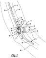
- an elbow prosthesis 10 is provided and includes a first stem component 12, a second stem component 14, and a hinge assembly 16 disposed generally between the first stem component 12 and the second stem component 14.
- the hinge assembly 16 joins the first stem component 12 and the second stem component 14 and facilitates relative movement between the first stem component 12 and the second stem component 14.
- the first stem component 12 may be received within a cavity (not shown) formed in a distal humerus 18 ( FIG. 1 ) and may include an elongate, tapered body 20, a first arm 22, a second arm 24, and a hook portion 26.
- the tapered body 20 may extend in an opposite direction than the first arm 22 and the second arm 24 and may be received within a channel formed in the humerus 18.
- the tapered body 20 may be secured within the channel formed in the humerus 18 by applying a force to the body 20 along a longitudinal axis thereof.
- the channel formed in the humerus 18 may include a female taper that decreases in size in a direction extending from the distal humerus to the proximal humerus.
- the female taper formed in the channel of the humerus 18 may cooperate with the male taper of the tapered body 20 to allow the tapered body 20 to frictionally engage the female taper of the humerus 18, thereby fixing the body 20 within and relative to the humerus 18.
- Bone cement and/or other suitable adhesives may also be used to secure the body 20 within the humerus 18.
- the first arm 22 and the second arm 24 may extend in an opposite direction than the tapered body 20 and may cooperate to provide the first stem component 12 with a substantially U-shaped channel 28.
- the U-shaped channel 28 may be formed by a side surface 30 of the first arm 22, a side surface 32 of the second arm 24, and an arcuate surface 34 that extends generally between and connects the side surfaces 30, 32.
- the first arm 22 may include a bore 36 and a distal end surface 38.
- the second arm 24 may include a bore 40 and a distal end surface 42.
- the bores 36, 40 of the first arm 22 and the second arm 24, respectively, may cooperate with the hinge assembly 16 to position and retain the hinge assembly 16 between the side surface 30 of the first arm 22 and the side surface 32 of the second arm 24, as will be described in greater detail below.
- the hook portion 26 may extend from a junction of the tapered body 20 and the first and second arms 22, 24. Further, the hook portion 26 may be spaced apart and separated from the tapered body 20 and may include an attachment aperture 44. Spacing the hook portion 26 from the tapered body 20 may permit a portion of the humerus 18 to be received generally between the tapered body 20 and the hook portion 26. As such, the hook portion 26 may oppose a portion of the humerus 18, which may permit a fastener (not shown) to be received through the attachment aperture 44 to secure the hook portion 26 and, thus, the first stem component 12, to the humerus 18. As with the tapered body 20, a suitable bone cement and/or adhesive may be used in conjunction with the hook portion 26 and the humerus 18 to secure the hook portion 26 to the humerus 18.
- the second stem component 14 is joined to the first stem component 12 via the hinge assembly 16 and may include an elongate, tapered body 46 and an attachment feature 48.
- the tapered body 46 may be received within a channel (not shown) formed in the ulna 50 ( FIG. 1 ).
- the channel formed in the ulna 50 may include a female taper such that when the male taper of the body 46 is inserted into the channel and a force is applied along a longitudinal axis of the body 46, the male taper of the body 46 engages the female taper of the channel, thereby joining the body 46 to the ulna 50 via a friction fit.
- the tapered body 46 may further be attached to the channel of the ulna 50 via a suitable bone cement and/or other adhesive.
- the attachment feature 48 may be formed at one end of the second stem component 14 and may include a bore 52 and an outer, arcuate surface 54.
- the bore 52 may include a series of retention features 56 that cooperate with the hinge assembly 16 to retain a portion of the hinge assembly 16 within the attachment feature 48.
- the attachment feature 48 may include an attachment aperture 58 that is formed through a wall of the attachment feature 48 and extends generally between the arcuate surface 54 and the bore 52. As such, the attachment aperture 58 may provide communication with the bore 52 from an area outside the attachment feature 48. In one configuration, the attachment aperture 58 may receive a fastener (not shown) to secure a portion of the hinge assembly 16 within the attachment feature 48, as will be described in greater detail below.
- the hinge assembly 16 is disposed at a junction of the first stem component 12 and the second stem component 14 and includes a first condyle 60, a second condyle 62, and a bearing member 64.
- the first condyle 60 may include an articulating surface 66, a channel 68, and a bore 70 formed in a substantially flat surface 72.
- the articulating surface 66 may provide the first condyle 60 with a substantially hemispherical shape that is matingly received by the bearing member 64 to allow the first condyle 60 to articulate within and relative to the bearing member 64 about the articulating surface 66.
- the channel 68 may be formed on an opposite side of the first condyle 60 from the articulating surface 66 and may include a shape that matingly receives the distal end surface 42 of the second arm 24. Providing the channel 68 with the same shape as the distal end surface 42 of the second arm 24 allows the second arm 24 to be properly positioned relative to and within the channel 68 when the second arm 24 is received by the first condyle 60.
- the bore 70 of the first condyle 60 may be aligned with the bore 40 of the second arm 24. Alignment between the bore 40 formed in the second arm 24 and the bore 70 formed in the first condyle 60 allows a fastener (not shown) to be inserted into and through the bores 40, 70 to fix the first condyle 60 for movement with the second arm 24.
- the second condyle 62 may include a medial component 74 and a lateral component 76.
- the terms “medial” and “lateral” are used to describe components 74 and 76 relative to a bone axis and are not necessarily “medial” and “lateral” to the body.
- the medial component 74 may include an articulating surface 78, a pocket 80, and a bore 82 formed in a substantially flat surface 84.
- the medial component 74 may additionally include a projection 86 extending from an opposite side of the medial component 74 than the articulating surface 78.
- the articulating surface 78 may be rotatably attached to the bearing member 64 to rotatably support the medial component 74 relative to the bearing member 64.
- the pocket 80 may be formed into the articulating surface 78 ( FIGS. 9 and 10 ) and may receive the first arm 22 therein. Specifically, the first arm 22 may be inserted into the pocket 80 until the distal end surface 38 of the first arm 22 contacts an end surface 88 of the pocket ( FIGS. 5 and 6 ). At this point, the first arm 22 is fully inserted into the pocket 80 such that the bore 82 of the second condyle 62 is aligned with the bore 36 of the first arm 22.
- alignment between the bore 36 of the first arm 22 and the bore 82 of the second condyle 62 allows a fastener (not shown) to be inserted into and through the bores 36, 82 to fix the medial component 74 for movement with the first arm 22.
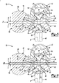
- the projection 86 may extend from the medial component 74 and may be offset from an axis of rotation (R) of the medial component 74. Specifically, a central axis (C) extending through a center of the projection 86 may be offset from the axis of rotation (R) of the medial component 74 by a distance (D), as shown in FIGS. 5 and 6 . In short, the projection 86 may be eccentric from the axis of rotation (R) of the medial component 74.
- the lateral component 76 is rotatably attached to the medial component 74 and may include an engagement surface 90 and a blind bore 92 formed on an opposite side of the lateral component 76 than the engagement surface 90.
- the blind bore 92 may include a female taper that receives the projection 86 of the medial component 74.
- the projection 86 may include a male taper that rotatably receives the female taper of the blind bore 92 to rotatably attach the lateral component 76 to the medial component 74.
- the blind bore 92 may be formed in the lateral component 76 such that the blind bore 92 is eccentric from a central axis of the lateral component 76 (axis of rotation (R) in FIG. 5 ) in a similar fashion as the projection 86 is eccentric to the axis of rotation (R) of the medial component 74.
- the blind bore 92 may include a central axis that is concentric with the central axis (C) of the projection 86.
- the central axis of the blind bore 92 may be offset relative to the central axis of the lateral component 76 by the distance (D), as represented in FIGS. 5 and 7 ( FIGS. 5 and 7 show the central axis of the lateral component 76 as being concentric with the axis of rotation (R) of the medial component 74 when the lateral component 76 is in the neutral state).
- the blind bore 92 is eccentric from the central axis of the lateral component 76 and, further, because the projection 86 is eccentric from an axis of rotation of the medial component 74, rotation of the lateral component 76 relative to the medial component 74 about the projection 86 causes the lateral component 76 to move from a neutral state ( FIG. 5 ) to an articulated state ( FIG. 6 ).
- the offset of the blind bore 92 from the central axis of the lateral component 76 and the offset of the projection 86 from the axis of rotation of the medial component 74 are equal, which allows the lateral component 76 to be positioned in neutral state.
- Rotation of the lateral component 76 about the projection 86 results in a net offset (i.e., in the plane of FIG. 6 ) of the lateral component 76 in the direction (Y).
- Such adjustment of the lateral component 76 relative to the medial component 74 allows the engagement surface 90 of the lateral component 76 to be properly positioned relative to the head of the proximal radius 94 ( FIG. 1 ) when the elbow prosthesis 10 is installed by a surgeon.
- the bearing member 64 may be received by the attachment feature 48 and may include a first bearing surface 96, a second bearing surface 98, a central bore 100, and a series of retention features 102.
- the bearing member 64 may be positioned within and received by the bore 52 of the attachment feature 48 such that the retention features 102 cooperate with the retention features 56 to retain and position the bearing member 64 within the bore 52.
- a fastener (not shown) may be received through the attachment aperture 58 and may engage the bearing member 64 to retain the bearing member 64 in a desired position within the bore 52.
- the first bearing surface 96 may oppose the first condyle 60 such that the articulating surface 66 is in contact with the first bearing surface 96. Accordingly, when the first condyle 60 is moved with the second arm 24 of the first stem component 12 relative to the second stem component 14, the articulating surface 66 moves relative to and is in engagement with the first bearing surface 96 of the bearing member 64.
- the second bearing surface 98 may oppose and receive the second condyle 62 such that the articulating surface 78 of the medial component 74 engages and is in contact with the second bearing surface 98. Accordingly, when the medial component 74 moves with the first arm 22 of the first stem component 12 relative to the second stem component 14, the articulating surface 78 moves relative to and is engagement with the second bearing surface 98.
- the central bore 100 may extend between the first bearing surface 96 and the second bearing surface 98 and may include a series of extensions 104 ( FIG. 2 ) that are formed into the bearing member 64.
- the extensions 104 may radiate from the central bore 100 and may extend into the first bearing surface 96 and the second bearing surface 98.
- the extensions 104 may cooperate with the central bore 100 to provide the bearing member 64 with a degree of flexibility at the first bearing surface 96 and the second bearing surface 98 proximate to the central bore 100.
- the flexibility provided by the central bore 100 and the extensions 104 allows the first bearing surface 96 and the second bearing surface 98 to flex during movement of the first condyle 60 and the second condyle 62 relative to the bearing member 64 during relative movement between the first stem component 12 and the second stem component 14.
- elbow prosthesis 10 during a total elbow arthroplasty procedure will be described in detail.
- the first stem component 12 may be received by a channel formed in the humerus 18 and the second stem component 14 may be received in a channel formed in the ulna 50, as described above.
- the hinge assembly 16 may be assembled to the first stem component 12 and to the second stem component 14 to permit relative movement between the first stem component 12 and the second stem component 14.
- the hinge assembly 16 may be assembled to the first stem component 12 and to the second stem component 14 prior to installation of the first stem component 12 into the humerus 18 and prior to installation of the second stem component 14 into the ulna 50. Nonetheless, attachment of the hinge assembly 16 to the first stem component 12 and to the second stem component 14 will be described hereinafter following installation of the first stem component 12 into the humerus 18 and following installation of the second stem component 14 into the ulna 50.
- a surgeon may initially create an incision proximate to an elbow joint of a patient to gain access to the distal end of the humerus 18, the proximal end of the ulna 50, and the head of the proximal radius 94.
- the humerus 18 may be prepared by forming a channel therein.
- the channel formed into the humerus 18 may include a female taper that receives the male tapered body 20 of the first stem component 12.
- a force may be applied to the tapered body 20 of the first stem component 12 to insert the first stem component 12 into the channel of the humerus 18, thereby creating a friction fit between the tapered body 20 of the first stem component 12 and the channel.
- Bone cement and/or a suitable adhesive may also be used to secure the first stem component 12 within the humerus 18.
- the second stem component 14 may be inserted into a channel formed in the ulna 50 in a similar fashion as described above with respect to the first stem component 12. Namely, a channel having a female taper may be formed in the ulna 50 and may receive the male tapered body 46 of the second stem component 14. A force may be applied in a direction substantially along a longitudinal axis of the second stem component 14 to drive the second stem component 14 into the channel formed in the ulna 50.
- the friction fit fixes the second stem component 14 for movement with the ulna 50.
- Bone cement and/or a suitable adhesive may also be used to secure the second stem component 14 within the ulna 50.
- the bearing member 64 of the hinge assembly 16 may initially be positioned relative to the second stem component 14 such that the bearing member 64 opposes the bore 52 formed in the attachment feature 48.
- the bearing member 64 may be properly aligned relative to the attachment feature 48 by aligning the retention features 102 of the bearing member 64 relative to the retention features 56 of the bore 52. Once the retention features 102 of the bearing member 64 are properly aligned with the retention features 56 of the bore 52, the bearing member 64 may be moved into the attachment feature 48 of the second stem component 14.
- a fastener (not shown) may be inserted into the attachment aperture 58 of the attachment feature 48 and may engage the bearing member 64 to fix a position of the bearing member 64 relative to and within the bore 52 of the attachment feature 48.
- the bearing member 64 is fixed relative to the second stem component 14 and is restricted from being removed from the bore 52 by the fastener received through the attachment aperture 58 and is restricted from rotating within the bore 52 due to engagement between the retention features 102 of the bearing member 64 and the retention features 56 of the bore 52.
- the first condyle 60 may be attached to the second arm 24 of the first stem component 12 by inserting the second arm 24 into the channel 68.
- the second arm 24 may be advanced into the channel 68 until the distal end surface 42 of the second arm 24 abuts a distal end of the channel 68.
- the bore 40 formed through the second arm 24 may be aligned with the bore 70 formed through the first condyle 60.
- a fastener (not shown) may be inserted through the bore 70 of the first condyle 60 and may be inserted through the bore 40 formed in the second arm 24 to fix the first condyle 60 for movement with the second arm 24 of the first stem component 12.
- the first condyle 60 may be positioned relative to and received by the first bearing surface 96 of the bearing member 64 such that the articulating surface 66 of the first condyle 60 opposes and is in contact with the first bearing surface 96 of the bearing member 64. Accordingly, when the first stem component 12 is moved relative to the second stem component 14, the articulating surface 66 may be in contact with and may bear against the first bearing surface 96 of the bearing member 64.
- the second condyle 62 may be attached to the first arm 22 of the first stem component 12 by inserting the first arm 22 into the pocket 80 formed in the medial component 74.
- the first arm 22 may be advanced into the pocket 80 until the distal end surface 38 of the first arm 22 contacts the end surface 88 of the pocket 80.
- the bore 36 formed through the first arm 22 may be aligned with the bore 82 of the medial component 74.
- a fastener (not shown) may be received through the bore 82 of the medial component 74 and may be received through the bore 36 of the first arm 22 such that the medial component 74 is fixed for movement with the first stem component 12. Accordingly, when the first stem component 12 is moved relative to the second stem component 14, the medial component 74 is likewise moved relative to the second stem component 14.
- the medial component 74 may be positioned relative to and may be received by the second bearing surface 98 of the bearing member 64. Specifically, the articulating surface 78 of the medial component 74 may be received by and may be in contact with the second bearing surface 98 such that when the medial component 74 is moved relative to the second stem component 14, the articulating surface 78 of the medial component 74 is in contact with and bears against the second bearing surface 98 of the bearing member 64.
- the lateral component 76 may be attached to the medial component 74 by aligning the blind bore 92 of the lateral component 76 with the projection 86 of the medial component 74. A force may be applied to the lateral component 76 to cause the projection 86 of the medial component 74 to be received within the blind bore 92. When the lateral component 76 is initially installed on the medial component 74, the lateral component 76 may be in a neutral state ( FIG. 7 ) such that the axis of rotation (R) of the medial component 74 is aligned with the central axis of the lateral component 76.
- a force may be applied to the lateral component 76 to cause the lateral component 76 to rotate relative to the medial component 74 about the projection 86. Because the center (C) of the projection 86 is offset from the axis of rotation (R) of the medial component 74 and, further, because a center of the blind bore 92 is offset from the central axis of the lateral component 76, rotation of the lateral component 76 about the projection 86 causes the lateral component 76 to articulate and move relative to the medial component 74 in a linear direction.
- rotation of the lateral component 76 about the projection 86 may result in a net offset (i.e., in the plane of FIG. 6 ) of the lateral component 76 in the direction (Y).
- Such movement may be performed by the surgeon when installing the elbow prosthesis 10 to allow the lateral component 76 of the second condyle 62 to be properly tensioned and in contact with the head of the proximal radius 94.
- a force may be applied to the lateral component 76 to fully insert the projection 86 into the blind bore 92 of the lateral component 76.
- the projection 86 may include a male taper and the blind bore 92 may include a female taper. Accordingly, when the projection 86 is driven into the blind bore 92, engagement between the male taper of the projection 86 and the female taper of the blind bore 92 fixes a rotational position of the lateral component 76 relative to the medial component 74 and prevents further movement of the lateral component 76 relative to the medial component 74.
- the surgeon may apply a force to one or both of the first stem component 12 and the second stem component 14 to ensure that the hinge assembly 16 provides a desired range of motion.
- Applying a force to one or both of the first stem component 12 and the second stem component 14 causes the first condyle 60 to move relative to the bearing member 64 and causes the second condyle 62 to move relative to the bearing member 64.
- the articulating surface 66 of the first condyle 60 engages and moves relative to the first bearing surface 96 of the bearing member 64.
- the articulating surface 78 of the medial component 74 engages and moves relative to the second bearing surface 98 of the bearing member 64.
- the foregoing movement likewise causes the engagement surface 90 of the lateral component 76 to engage and move relative to the head of the proximal radius 94.
- Engagement between the engagement surface 90 of the lateral component 76 and the head of the proximal radius 94 provides stability to the medial component 74 and enhances articulation of the lateral component 76 with the head of the proximal radius 94.
- Providing the lateral component 76 with a degree of adjustment relative to the medial component 74 allows the surgeon to adjust the position of the lateral component 76 relative to the head of the proximal radius 94 during surgery and, therefore, ensures that the lateral component 76 will adequately support and articulate relative to the head of the proximal radius 94 during use of the elbow prosthesis 10 and through the range of motion.
- a second condyle 62a is provided for use with the elbow prosthesis 10.
- the second condyle 62a replaces the second condyle 62 and may include a medial component 74a, a lateral component 76a, and an intermediate component 106 disposed generally between the medial component 74a and the lateral component 76a.
- the intermediate component may include a first projection 108, a second projection 110, and a main body 112 disposed between the first projection 108 and the second projection 110.
- the first projection 108 may include a male taper and may be received within a blind bore 114 formed in the medial component 74a.
- the blind bore 114 may include a female taper and may matingly receive the male taper of the first projection 108.
- the first projection 108 may be offset from an axis of rotation (Ra) of the medial component 74a.
- a central axis (Ca 1 ) of the first projection 108 may be spaced apart and separated from the axis of rotation (Ra) of the medial component 74a by a distance (D 1 ). Because the central axis (Ca 1 ) of the first projection 108 may be offset from the axis of rotation (Ra) of the medial component 74a, the first projection 108 and, thus, the blind bore 114, are eccentric from the axis of rotation (Ra) of the medial component 74a.
- the second projection 110 may be received by a blind bore 116 formed into the lateral component 76a.
- the blind bore 116 may include a female taper that receives a male taper of the second projection 110 when the second projection 110 is inserted into the blind bore 116.
- the second projection 110 may include a central axis (Ca 2 ) that is offset from a central axis of the lateral component 76a by a distance (D 2 ).
- a central axis (Ca 2 ) that is offset from a central axis of the lateral component 76a by a distance (D 2 ).
- the central axis of the lateral component 76a is concentric with the axis of rotation (Ra) of the medial component 74a. Accordingly, the distance (D 2 ) is shown relative to the axis of rotation (Ra) of the medial component 74a. Because the second projection 110 and, thus, the blind bore 116, are offset from the central axis of the lateral component 76a, the second projection 110 and the blind bore 116 are eccentric from the central axis of the lateral component 76a.
- a force may be applied to the lateral component 76a to rotate the lateral component 76 about the second projection 110. Because the second projection 110 is offset from the axis of rotation (Ra) of the medial component 74a and from a central axis of the lateral component 76a, rotation of the lateral component 76a about the second projection 110 results in a net offset (i.e., in the plane of FIG. 11 ) of the lateral component 76 in the direction (Y).
- such rotation of the lateral component 76a may be performed by the surgeon to properly position the lateral component 76a relative to the head of the proximal radius 94 to allow the engagement surface 90 to properly engage the head of the proximal radius 94.
- the surgeon may additionally apply a rotational force to the intermediate component 106, thereby causing the intermediate component 106 to rotate relative to the medial component 74a.
- Such rotation of the intermediate component 106 relative to the medial component 74a causes the intermediate component 106 to rotate about the first projection 108.
- the first projection 108 is eccentric from the axis of rotation of the medial component 74a
- rotation of the intermediate component 106 relative to the medial component 74a results in a net offset (i.e., in the plane of FIG. 11 ) of the intermediate component 106 in the direction (Z).
- the net offset of the intermediate component 106 in the direction (Z) likewise causes a net offset (i.e., in the plane of FIG. 11 ) of the lateral component 76a in the direction (Y), as the lateral component 76a is attached to the first projection 108 of the intermediate component 106 via the second projection 110.
- the surgeon may rotate the lateral component 76 about the second projection 110 relative to the intermediate component 106 and may likewise rotate the lateral component 76a along with the intermediate component 106 about the first projection 108 relative to the medial component 74a. While the surgeon may rotate the lateral component 76a relative to the intermediate component 106 and may rotate the intermediate component 106 relative to the medial component 74a, the surgeon could alternatively rotate only the lateral component 76a relative to the intermediate component 106 or could rotate only the intermediate component 106 relative to the medial component 74a. In short, the surgeon could rotate the lateral component 76a relative to the intermediate component 106 and/or may rotate the intermediate component 106 relative to the medial component 74a. Any or all of the foregoing operations may be performed by the surgeon to properly position the engagement surface 90 of the lateral component 76 relative to the head of the proximal radius 94 during surgery.
- a force may be applied to the lateral component 76 to drive the second projection 110 into the blind bore 116 to allow the male taper of the second projection 110 to fully engage the female taper of the blind bore 116 to fix the lateral component 76 for movement with the intermediate component 106.
- a force may be applied to the intermediate component 106 (via the lateral component 76a) to drive the first projection 108 into the blind bore 114 to allow the male taper of the first projection 108 to fully engage the blind bore 114 of the medial component 74a.
- full engagement of the first projection 108 of the intermediate component 106 and the female taper of the blind bore 114 results in the intermediate component 106 being fixed for movement with the medial component 74a.
- the lateral component 76a is fixed for movement with the intermediate component 106 and the intermediate component 106 is fixed for movement with the medial component 74a, the lateral component 76a is fixed for movement with the medial component 74a.
- the relative position of the engagement surface 90 of the lateral component 76a relative to the head of the proximal radius 94 is likewise fixed.
- Adjustment of the engagement surface 90 of the lateral component 76 relative to the medial component 74a and the resulting contact of the engagement surface 90 with the head of the proximal radius 94 results in the lateral component 76a adequately supporting the elbow prosthesis 10 relative to the head of the proximal radius 94 while concurrently providing a desired articulation of the lateral component 76a relative to the head of the proximal radius 94.
- a second condyle 62b is provided for use with the elbow prosthesis 10.
- the second condyle 62b replaces the second condyle 62 and may include a medial component 74b and a lateral component 76b.
- the lateral component 76b may be attached to the medial component 74b by an intermediate component 118.
- the intermediate component 118 may include a projection 120 extending from a main body 122.
- the projection 120 may be received by an insert 124 positioned within a blind bore 126 formed in the lateral component 76b.
- the projection 120 may include a male taper that is matingly received by a tapered aperture 128 formed in the insert 124.
- the projection 120 may be offset from an axis of rotation (Rb) of the medial component 74b. Specifically, a central axis (Cb 1 ) of the projection 120 may be offset from the axis of rotation (Rb) of the medial component 74b by a distance (D 3 ). Accordingly, the projection 120 may be eccentric from the axis of rotation (Rb) of the medial component 74b.
- the insert 124 may likewise be offset from the axis of rotation (Rb) of the medial component 74b. Accordingly, a central axis (Cb 2 ) of the insert 124 may be offset from the axis of rotation (Rb) of the medial component 74b by a distance (D 4 ). Accordingly, the insert 124 may be eccentric from the axis of rotation (Rb) of the medial component 74b.
- a surgeon may apply a force to the lateral component 76b to rotate the lateral component and the insert 124 relative to and about the projection 120.
- Such rotation of the lateral component 76b and the insert 124 relative to and about the projection 120 results in the lateral component 76b moving in the direction (Y) due to the insert 124 being eccentric from the axis of rotation (Rb) of the medial component 74b.
- the force applied to the lateral component 76b may also cause rotation of the insert 124 relative to and about the projection 120, which may further result in movement of the lateral component 76b in the direction (Y).
- movement of the lateral component 76b in the direction (Y) allows the surgeon to properly position the engagement surface 90 of the lateral component 76b relative to the head of the proximal radius 94.
- a force may be applied to the lateral component 76b to cause the male taper of the projection 120 to fully engage the tapered aperture 128 of the insert 124 and may cause the male taper of the insert 124 to fully engage the female taper of the blind bore 126 to fix a position of the lateral component 76b relative to the intermediate component 118.
- Fixing a position of the lateral component 76b relative to the intermediate component 118 likewise fixes a position of the lateral component 76b relative to the medial component 74b and, thus, maintains the adjusted position of the lateral component 76b performed by the surgeon. Accordingly, use of the second condyle 62b in conjunction with the elbow prosthesis 10 ensures that the lateral component 76b supports the elbow prosthesis 10 relative to the head of the proximal radius 94 to provide a desired range of articulation.
Landscapes
- Health & Medical Sciences (AREA)
- Orthopedic Medicine & Surgery (AREA)
- Physical Education & Sports Medicine (AREA)
- Cardiology (AREA)
- Oral & Maxillofacial Surgery (AREA)
- Transplantation (AREA)
- Engineering & Computer Science (AREA)
- Biomedical Technology (AREA)
- Heart & Thoracic Surgery (AREA)
- Vascular Medicine (AREA)
- Life Sciences & Earth Sciences (AREA)
- Animal Behavior & Ethology (AREA)
- General Health & Medical Sciences (AREA)
- Public Health (AREA)
- Veterinary Medicine (AREA)
- Prostheses (AREA)
Applications Claiming Priority (2)
| Application Number | Priority Date | Filing Date | Title |
|---|---|---|---|
| US13/800,740 US9039779B2 (en) | 2013-03-13 | 2013-03-13 | Adjustable lateral articulating condyle |
| PCT/US2014/021970 WO2014159108A1 (en) | 2013-03-13 | 2014-03-07 | Adjustable lateral articulating condyle |
Publications (2)
| Publication Number | Publication Date |
|---|---|
| EP2967881A1 EP2967881A1 (en) | 2016-01-20 |
| EP2967881B1 true EP2967881B1 (en) | 2017-02-01 |
Family
ID=50349983
Family Applications (1)
| Application Number | Title | Priority Date | Filing Date |
|---|---|---|---|
| EP14712538.9A Active EP2967881B1 (en) | 2013-03-13 | 2014-03-07 | Adjustable lateral articulating condyle |
Country Status (7)
| Country | Link |
|---|---|
| US (1) | US9039779B2 (enExample) |
| EP (1) | EP2967881B1 (enExample) |
| JP (1) | JP6491185B2 (enExample) |
| AU (1) | AU2014241352B2 (enExample) |
| CA (1) | CA2904427C (enExample) |
| ES (1) | ES2616117T3 (enExample) |
| WO (1) | WO2014159108A1 (enExample) |
Families Citing this family (5)
| Publication number | Priority date | Publication date | Assignee | Title |
|---|---|---|---|---|
| EP2514391A1 (de) * | 2011-04-20 | 2012-10-24 | Deru GmbH | Gelenkprothese mit einem Beugescharnier mit Spreizachse |
| US8840673B2 (en) * | 2011-09-21 | 2014-09-23 | Linares Medical Devices, Llc | Implantable elbow joint assembly with spherical inter-support |
| USD867593S1 (en) * | 2016-09-22 | 2019-11-19 | Baugh Medical Organization, Llc | Prosthesis for post tissue recovery |
| US11020234B2 (en) | 2018-02-20 | 2021-06-01 | Synthes Gmbh | Radial head orthopedic implant apparatus and method of using same |
| CN115836931A (zh) * | 2023-02-24 | 2023-03-24 | 北京爱康宜诚医疗器材有限公司 | 一种肘关节假体 |
Family Cites Families (96)
| Publication number | Priority date | Publication date | Assignee | Title |
|---|---|---|---|---|
| US3547115A (en) | 1968-04-05 | 1970-12-15 | Peter S Stevens | Osteoarticular prosthetic method |
| GB1285460A (en) | 1969-12-24 | 1972-08-16 | Nat Res Dev | Improvements relating to replacement elbow joints |
| US3694821A (en) | 1970-11-02 | 1972-10-03 | Walter D Moritz | Artificial skeletal joint |
| US3824630A (en) | 1972-06-23 | 1974-07-23 | Zimmer Mfg Co | Prosthetic joint for total knee replacement |
| GB1445573A (en) | 1972-11-30 | 1976-08-11 | Nat Res Dev | Prosthetic devices |
| GB1452924A (en) | 1973-01-31 | 1976-10-20 | Nat Res Dev | Prosthetic devices |
| US3816854A (en) | 1973-07-03 | 1974-06-18 | A Schlein | Prosthesis for total arthroplasty of the elbow joint |
| GB1488247A (en) | 1973-10-15 | 1977-10-12 | Nat Res Dev | Endoprosthetic devices |
| GB1509533A (en) | 1974-05-03 | 1978-05-04 | Nat Res Dev | Endo-prosthetic devices |
| GB1514468A (en) | 1974-07-03 | 1978-06-14 | Nat Res Dev | Endoprosthetic elbow joint devices |
| US3990117A (en) | 1975-01-22 | 1976-11-09 | Pritchard Rowland W | Elbow joint prosthesis |
| DE2625744A1 (de) | 1975-06-11 | 1976-12-23 | Downs Surgical Ltd | Ellbogenprothese |
| US4011603A (en) | 1975-08-29 | 1977-03-15 | Laure Prosthetics, Inc. | Finger joint implant |
| US3991425A (en) | 1975-11-20 | 1976-11-16 | Minnesota Mining And Manufacturing Company | Prosthetic bone joint devices |
| US4079469A (en) | 1975-12-12 | 1978-03-21 | Thomas Gordon Wadsworth | Elbow joint endoprosthesis |
| US4001603A (en) | 1976-02-25 | 1977-01-04 | National Semiconductor Corporation | Emitter load switching circuit |
| GB1550010A (en) | 1976-12-15 | 1979-08-08 | Ontario Research Foundation | Surgical prosthetic device or implant having pure metal porous coating |
| US4131956A (en) | 1977-02-14 | 1979-01-02 | Richards Manufacturing Company, Inc. | Elbow prosthesis |
| US4301552A (en) | 1977-05-20 | 1981-11-24 | Wright Manufacturing Company | Endoprosthetic joint device |
| GB1520162A (en) | 1977-05-25 | 1978-08-02 | Nat Res Dev | Bone joint prosthesis |
| GB1601576A (en) | 1977-06-01 | 1981-10-28 | Howmedica | Elbow prosthesis |
| US4129902A (en) | 1977-07-11 | 1978-12-19 | Harmon Stanley D | Elbow prosthesis |
| US4131957A (en) | 1977-08-12 | 1979-01-02 | General Atomic Company | Ball and socket prosthetic joint |
| DE2806717A1 (de) | 1978-02-14 | 1979-08-16 | Reinhard Dr Koelbel | Kuenstliches ellbogengelenk |
| US4194250A (en) | 1978-03-08 | 1980-03-25 | Codman & Shurtleff, Inc. | Load-stabilizing prosthetic joint and connecting component thereof |
| DE2811331A1 (de) | 1978-03-16 | 1979-09-27 | Schuett & Grundei Sanitaet | Ellenbogengelenk in form einer endovollprothese |
| JPS5526987A (en) | 1978-05-31 | 1980-02-26 | Wadsworth Thomas G | Elbow replacement prosthetic dentistry device |
| US4224697A (en) | 1978-09-08 | 1980-09-30 | Hexcel Corporation | Constrained prosthetic knee |
| US4352212A (en) | 1979-03-05 | 1982-10-05 | Howmedica, Inc. | Joint prosthesis |
| US4280231A (en) | 1979-06-14 | 1981-07-28 | Swanson Alfred B | Elbow prosthesis |
| US4259752A (en) | 1980-01-04 | 1981-04-07 | Julio Taleisnik | Endoprosthetic wrist joint |
| US4293963A (en) | 1980-02-14 | 1981-10-13 | Zimmer Usa, Inc. | Unrestrained elbow prosthesis |
| US4383337A (en) | 1980-10-22 | 1983-05-17 | Zimmer Usa, Inc. | Elbow prosthesis |
| US4479271A (en) | 1981-10-26 | 1984-10-30 | Zimmer, Inc. | Prosthetic device adapted to promote bone/tissue ingrowth |
| DE3223925C2 (de) | 1982-06-26 | 1986-07-31 | Feldmühle AG, 4000 Düsseldorf | Implantierbares Ellbogengelenk |
| US5030237A (en) | 1983-06-24 | 1991-07-09 | Queen's University At Kingston | Elbow prosthesis |
| US4659331A (en) | 1983-11-28 | 1987-04-21 | Regents Of University Of Michigan | Prosthesis interface surface and method of implanting |
| DE3417923A1 (de) | 1984-05-15 | 1985-11-21 | Th. Dr. 8700 Würzburg Stuhler | Endoprothese und duebel fuer die verankerung in einem material mit knochenartiger festigkeit |
| US4725280A (en) | 1986-03-28 | 1988-02-16 | Laure Prosthetics, Inc. | Finger implant |
| FR2610513B1 (fr) | 1987-02-09 | 1992-06-05 | Merle Michel | Prothese articulaire |
| EP0278184A1 (fr) | 1987-02-11 | 1988-08-17 | Thierry Hermann | Prothèse d'articulation, en particulier pour articulation de doigt |
| US4822364A (en) | 1987-12-21 | 1989-04-18 | New York Society For The Relief Of The Ruptured And Crippled, Maintaining The Hospital For Special Surgery | Elbow joint prosthesis |
| SU1567200A1 (ru) | 1988-05-23 | 1990-05-30 | М. Л Манук н, О. В Оганес н и Л. М. Манук н | Эндопротез коленного сустава |
| FR2634373B1 (fr) | 1988-07-25 | 1990-10-26 | Lebeguec Pierre | Prothese totale du genou |
| SU1560183A1 (ru) | 1988-07-26 | 1990-04-30 | О. Н. Гудушаури, Е. Д. Соломко и Б. Г. Зимлицкий | Эндопротез локтевого сустава |
| US4936853A (en) | 1989-01-11 | 1990-06-26 | Kirschner Medical Corporation | Modular knee prosthesis |
| US4927422A (en) | 1989-08-31 | 1990-05-22 | Boehringer Mannheim Corporation | Elbow arthroplasty instrumentation and surgical procedure |
| US5024670A (en) | 1989-10-02 | 1991-06-18 | Depuy, Division Of Boehringer Mannheim Corporation | Polymeric bearing component |
| DE3940728B4 (de) | 1989-12-09 | 2007-03-08 | Waldemar Link Gmbh & Co. Kg | Ellbogengelenk-Endoprothese |
| US5207711A (en) | 1990-01-08 | 1993-05-04 | Caspari Richard B | Knee joint prosthesis |
| DE4119226A1 (de) | 1991-06-11 | 1992-12-17 | Gmt Medizinische Technik Gmbh | Kniegelenkendoprothese |
| US5376121A (en) | 1991-08-06 | 1994-12-27 | Techmedica, Inc. | Dual constraint elbow prosthesis |
| WO1993002643A1 (en) | 1991-08-06 | 1993-02-18 | Huene Donald R | Bi-axial elbow joint replacement |
| US5282367A (en) | 1992-04-24 | 1994-02-01 | The Delfield Company | Refrigerated food preparation table and method |
| US5282867A (en) | 1992-05-29 | 1994-02-01 | Mikhail Michael W E | Prosthetic knee joint |
| US5665087A (en) | 1996-03-26 | 1997-09-09 | Huebner; Randall J. | Method and screw for repair of olecranon fractures |
| ATE181497T1 (de) | 1993-01-21 | 1999-07-15 | Sulzer Orthopaedie Ag | Künstliches handgelenk |
| US5380334A (en) | 1993-02-17 | 1995-01-10 | Smith & Nephew Dyonics, Inc. | Soft tissue anchors and systems for implantation |
| US5551871A (en) | 1993-03-05 | 1996-09-03 | Besselink; Petrus A. | Temperature-sensitive medical/dental apparatus |
| US5584835A (en) | 1993-10-18 | 1996-12-17 | Greenfield; Jon B. | Soft tissue to bone fixation device and method |
| US5549685A (en) | 1994-02-23 | 1996-08-27 | Zimmer, Inc. | Augmentation for an orthopaedic implant |
| US5840078A (en) | 1995-03-01 | 1998-11-24 | Yerys; Paul | Method and apparatus for mechanical attachment of soft tissue to bone tissue |
| DE19512854C1 (de) | 1995-04-06 | 1996-08-01 | Eska Medical Gmbh & Co | Fingergelenk |
| DE19521597A1 (de) | 1995-06-14 | 1996-12-19 | Kubein Meesenburg Dietmar | Künstliches Gelenk, insbesondere Endoprothese zum Ersatz natürlicher Gelenke |
| US5725541A (en) | 1996-01-22 | 1998-03-10 | The Anspach Effort, Inc. | Soft tissue fastener device |
| DE19620525A1 (de) | 1996-05-22 | 1997-11-27 | Gmt Medizinische Technik Gmbh | Ellbogengelenk-Endoprothese |
| US5725591A (en) | 1996-08-13 | 1998-03-10 | Johnson & Johnson Professional, Inc. | Acetabular bearing system |
| FR2758455B1 (fr) | 1997-01-23 | 1999-08-06 | Tornier Sa | Prothese totale de coude |
| FR2758975B1 (fr) | 1997-02-05 | 1999-04-30 | Ethnor | Materiel pour la fixation d'un tendon de muscle sur un os |
| US6027534A (en) | 1997-11-03 | 2000-02-22 | Deputy Orthopaedics, Inc. | Modular elbow |
| DE69822266T2 (de) | 1997-11-03 | 2005-02-24 | DePuy Orthopaedics, Inc., Warsaw | Modulare Ellenbogenprothese |
| US6162253A (en) | 1997-12-31 | 2000-12-19 | Iowa State University Research Foundation, Inc. | Total elbow arthroplasty system |
| EP1112049B1 (de) * | 1998-09-11 | 2003-11-26 | Argomedical AG | Implantierbare prothese mit zumindest zwei gegeneinander verstellbaren abschnitten sowie verwendung verstellbarer abschnitte |
| US6306171B1 (en) | 1998-12-09 | 2001-10-23 | Iowa State University Research Foundation, Inc. | Total elbow arthroplasty system |
| FR2793404B1 (fr) | 1999-05-14 | 2001-09-14 | Tornier Sa | Prothese de coude |
| SE516039C3 (sv) | 2000-03-23 | 2002-01-09 | Philippe Kopylov Ab | Ledyteersätnning för distala radioulnarleden |
| US6656225B2 (en) | 2000-04-10 | 2003-12-02 | Biomet Manufacturing Corp. | Modular radial head prostheses |
| US8932362B2 (en) | 2000-07-18 | 2015-01-13 | Biomet Manufacturing, Llc | Elbow prosthesis |
| US9561110B2 (en) | 2000-07-18 | 2017-02-07 | Encore Medical, L.P. | Elbow prosthesis |
| US10231839B2 (en) | 2000-07-18 | 2019-03-19 | Encore Medical, L.P. | Elbow prosthesis |
| AU2001276931A1 (en) | 2000-07-18 | 2002-01-30 | Biomet, Inc. | Elbow prosthesis |
| US6626906B1 (en) | 2000-10-23 | 2003-09-30 | Sdgi Holdings, Inc. | Multi-planar adjustable connector |
| JP4355844B2 (ja) * | 2000-11-22 | 2009-11-04 | 徹 勝呂 | 人工肘関節 |
| US8795379B2 (en) * | 2001-07-11 | 2014-08-05 | Biomet Manufacturing, Llc | Variable prosthesis |
| FR2829688B1 (fr) * | 2001-09-14 | 2003-11-21 | Fixano | Prothese totale d'articulation du coude |
| US20040102852A1 (en) | 2002-11-22 | 2004-05-27 | Johnson Erin M. | Modular knee prosthesis |
| US7452381B2 (en) | 2003-01-30 | 2008-11-18 | Mayo Foundation For Medical Education And Research | Radial head replacement system |
| FR2855397B1 (fr) | 2003-05-28 | 2005-07-15 | Tornier Sa | Prothese de coude |
| US7270665B2 (en) | 2003-06-11 | 2007-09-18 | Sdgi Holdings, Inc. | Variable offset spinal fixation system |
| WO2005086939A2 (en) | 2004-03-11 | 2005-09-22 | Acumed Llc | Systems for bone replacement |
| US7449028B2 (en) | 2004-10-29 | 2008-11-11 | Depuy Products, Inc. | Modular total elbow prosthesis, humeral component and associated kit |
| JP4919248B2 (ja) | 2005-05-31 | 2012-04-18 | 博泰 池上 | 人工肘関節 |
| US8012214B2 (en) | 2005-09-27 | 2011-09-06 | Randall Lane Acker | Joint prosthesis |
| US20080183291A1 (en) | 2007-01-29 | 2008-07-31 | Howmedica Osteonics Corp. | Resurfacing the tibial plateau |
| US7582118B2 (en) | 2007-02-06 | 2009-09-01 | Zimmer Technology, Inc. | Femoral trochlea prostheses |
| US8936647B2 (en) | 2012-06-22 | 2015-01-20 | Zimmer, Inc. | Elbow prosthesis |
-
2013
- 2013-03-13 US US13/800,740 patent/US9039779B2/en active Active
-
2014
- 2014-03-07 CA CA2904427A patent/CA2904427C/en active Active
- 2014-03-07 EP EP14712538.9A patent/EP2967881B1/en active Active
- 2014-03-07 JP JP2016500885A patent/JP6491185B2/ja active Active
- 2014-03-07 ES ES14712538.9T patent/ES2616117T3/es active Active
- 2014-03-07 AU AU2014241352A patent/AU2014241352B2/en active Active
- 2014-03-07 WO PCT/US2014/021970 patent/WO2014159108A1/en not_active Ceased
Non-Patent Citations (1)
| Title |
|---|
| None * |
Also Published As
| Publication number | Publication date |
|---|---|
| US20140277525A1 (en) | 2014-09-18 |
| ES2616117T3 (es) | 2017-06-09 |
| AU2014241352B2 (en) | 2017-11-09 |
| JP2016511088A (ja) | 2016-04-14 |
| US9039779B2 (en) | 2015-05-26 |
| EP2967881A1 (en) | 2016-01-20 |
| WO2014159108A1 (en) | 2014-10-02 |
| AU2014241352A1 (en) | 2015-11-05 |
| CA2904427C (en) | 2020-05-26 |
| JP6491185B2 (ja) | 2019-03-27 |
| CA2904427A1 (en) | 2014-10-02 |
Similar Documents
| Publication | Publication Date | Title |
|---|---|---|
| EP2574314B1 (en) | Rotatable patella drill guide | |
| EP2967881B1 (en) | Adjustable lateral articulating condyle | |
| US10052143B2 (en) | Tensioning instrument and related bone fixation systems and methods | |
| US20200155170A1 (en) | Flexible bone reamer | |
| KR101737907B1 (ko) | 임플란트 보유 시스템 및 뼈에 임플란트를 보유하기 위한 장치 | |
| JP2023162211A (ja) | インプラント、システムおよびそれを使用する方法 | |
| KR101197844B1 (ko) | 다중-축 나사용 키형 크라운 배향 | |
| US6602292B2 (en) | Mobile bearing patella prosthesis | |
| US8998912B2 (en) | Clamping patella drill guide | |
| EP2574292B1 (en) | Patella drilling system | |
| US10213318B2 (en) | Spinal cage device, system, and methods of assembly and use | |
| US9566162B2 (en) | Adjustable humeral tray for shoulder arthroplasty | |
| JP2017170179A (ja) | 自動保持形式圧縮スロットを有する髄内釘 | |
| JP2004351209A (ja) | 肘プロテーゼ | |
| JP2009523569A5 (enExample) | ||
| US20160287409A1 (en) | Insertion instrument with articulating wrist | |
| WO2015171200A1 (en) | Hingeable and fixable bone plate system | |
| DK2499999T3 (en) | Rygsøjleimplantat low | |
| US20070288020A1 (en) | Soft tissue fixation device for organs proximate shankbone | |
| EP4009892B1 (en) | Dynamic bone plate | |
| US10874444B2 (en) | Hinge plate assembly | |
| KR20220132663A (ko) | 보강된 고착을 위한 플랜지를 구비한 관절구체 및 이와 관련된 방법 |
Legal Events
| Date | Code | Title | Description |
|---|---|---|---|
| PUAI | Public reference made under article 153(3) epc to a published international application that has entered the european phase |
Free format text: ORIGINAL CODE: 0009012 |
|
| 17P | Request for examination filed |
Effective date: 20151013 |
|
| AK | Designated contracting states |
Kind code of ref document: A1 Designated state(s): AL AT BE BG CH CY CZ DE DK EE ES FI FR GB GR HR HU IE IS IT LI LT LU LV MC MK MT NL NO PL PT RO RS SE SI SK SM TR |
|
| AX | Request for extension of the european patent |
Extension state: BA ME |
|
| DAX | Request for extension of the european patent (deleted) | ||
| GRAP | Despatch of communication of intention to grant a patent |
Free format text: ORIGINAL CODE: EPIDOSNIGR1 |
|
| INTG | Intention to grant announced |
Effective date: 20160816 |
|
| GRAS | Grant fee paid |
Free format text: ORIGINAL CODE: EPIDOSNIGR3 |
|
| GRAA | (expected) grant |
Free format text: ORIGINAL CODE: 0009210 |
|
| AK | Designated contracting states |
Kind code of ref document: B1 Designated state(s): AL AT BE BG CH CY CZ DE DK EE ES FI FR GB GR HR HU IE IS IT LI LT LU LV MC MK MT NL NO PL PT RO RS SE SI SK SM TR |
|
| REG | Reference to a national code |
Ref country code: GB Ref legal event code: FG4D |
|
| REG | Reference to a national code |
Ref country code: FR Ref legal event code: PLFP Year of fee payment: 4 |
|
| REG | Reference to a national code |
Ref country code: CH Ref legal event code: EP Ref country code: CH Ref legal event code: NV Representative=s name: MICHELI AND CIE SA, CH Ref country code: AT Ref legal event code: REF Ref document number: 864927 Country of ref document: AT Kind code of ref document: T Effective date: 20170215 |
|
| REG | Reference to a national code |
Ref country code: IE Ref legal event code: FG4D |
|
| REG | Reference to a national code |
Ref country code: DE Ref legal event code: R096 Ref document number: 602014006578 Country of ref document: DE |
|
| REG | Reference to a national code |
Ref country code: NL Ref legal event code: MP Effective date: 20170201 |
|
| REG | Reference to a national code |
Ref country code: ES Ref legal event code: FG2A Ref document number: 2616117 Country of ref document: ES Kind code of ref document: T3 Effective date: 20170609 |
|
| REG | Reference to a national code |
Ref country code: LT Ref legal event code: MG4D |
|
| REG | Reference to a national code |
Ref country code: AT Ref legal event code: MK05 Ref document number: 864927 Country of ref document: AT Kind code of ref document: T Effective date: 20170201 |
|
| PG25 | Lapsed in a contracting state [announced via postgrant information from national office to epo] |
Ref country code: FI Free format text: LAPSE BECAUSE OF FAILURE TO SUBMIT A TRANSLATION OF THE DESCRIPTION OR TO PAY THE FEE WITHIN THE PRESCRIBED TIME-LIMIT Effective date: 20170201 Ref country code: NO Free format text: LAPSE BECAUSE OF FAILURE TO SUBMIT A TRANSLATION OF THE DESCRIPTION OR TO PAY THE FEE WITHIN THE PRESCRIBED TIME-LIMIT Effective date: 20170501 Ref country code: IS Free format text: LAPSE BECAUSE OF FAILURE TO SUBMIT A TRANSLATION OF THE DESCRIPTION OR TO PAY THE FEE WITHIN THE PRESCRIBED TIME-LIMIT Effective date: 20170601 Ref country code: LT Free format text: LAPSE BECAUSE OF FAILURE TO SUBMIT A TRANSLATION OF THE DESCRIPTION OR TO PAY THE FEE WITHIN THE PRESCRIBED TIME-LIMIT Effective date: 20170201 Ref country code: HR Free format text: LAPSE BECAUSE OF FAILURE TO SUBMIT A TRANSLATION OF THE DESCRIPTION OR TO PAY THE FEE WITHIN THE PRESCRIBED TIME-LIMIT Effective date: 20170201 Ref country code: GR Free format text: LAPSE BECAUSE OF FAILURE TO SUBMIT A TRANSLATION OF THE DESCRIPTION OR TO PAY THE FEE WITHIN THE PRESCRIBED TIME-LIMIT Effective date: 20170502 |
|
| PG25 | Lapsed in a contracting state [announced via postgrant information from national office to epo] |
Ref country code: SE Free format text: LAPSE BECAUSE OF FAILURE TO SUBMIT A TRANSLATION OF THE DESCRIPTION OR TO PAY THE FEE WITHIN THE PRESCRIBED TIME-LIMIT Effective date: 20170201 Ref country code: AT Free format text: LAPSE BECAUSE OF FAILURE TO SUBMIT A TRANSLATION OF THE DESCRIPTION OR TO PAY THE FEE WITHIN THE PRESCRIBED TIME-LIMIT Effective date: 20170201 Ref country code: BG Free format text: LAPSE BECAUSE OF FAILURE TO SUBMIT A TRANSLATION OF THE DESCRIPTION OR TO PAY THE FEE WITHIN THE PRESCRIBED TIME-LIMIT Effective date: 20170501 Ref country code: LV Free format text: LAPSE BECAUSE OF FAILURE TO SUBMIT A TRANSLATION OF THE DESCRIPTION OR TO PAY THE FEE WITHIN THE PRESCRIBED TIME-LIMIT Effective date: 20170201 Ref country code: NL Free format text: LAPSE BECAUSE OF NON-PAYMENT OF DUE FEES Effective date: 20170201 Ref country code: PT Free format text: LAPSE BECAUSE OF FAILURE TO SUBMIT A TRANSLATION OF THE DESCRIPTION OR TO PAY THE FEE WITHIN THE PRESCRIBED TIME-LIMIT Effective date: 20170601 Ref country code: RS Free format text: LAPSE BECAUSE OF FAILURE TO SUBMIT A TRANSLATION OF THE DESCRIPTION OR TO PAY THE FEE WITHIN THE PRESCRIBED TIME-LIMIT Effective date: 20170201 Ref country code: PL Free format text: LAPSE BECAUSE OF FAILURE TO SUBMIT A TRANSLATION OF THE DESCRIPTION OR TO PAY THE FEE WITHIN THE PRESCRIBED TIME-LIMIT Effective date: 20170201 |
|
| PG25 | Lapsed in a contracting state [announced via postgrant information from national office to epo] |
Ref country code: CZ Free format text: LAPSE BECAUSE OF FAILURE TO SUBMIT A TRANSLATION OF THE DESCRIPTION OR TO PAY THE FEE WITHIN THE PRESCRIBED TIME-LIMIT Effective date: 20170201 Ref country code: SK Free format text: LAPSE BECAUSE OF FAILURE TO SUBMIT A TRANSLATION OF THE DESCRIPTION OR TO PAY THE FEE WITHIN THE PRESCRIBED TIME-LIMIT Effective date: 20170201 Ref country code: EE Free format text: LAPSE BECAUSE OF FAILURE TO SUBMIT A TRANSLATION OF THE DESCRIPTION OR TO PAY THE FEE WITHIN THE PRESCRIBED TIME-LIMIT Effective date: 20170201 Ref country code: RO Free format text: LAPSE BECAUSE OF FAILURE TO SUBMIT A TRANSLATION OF THE DESCRIPTION OR TO PAY THE FEE WITHIN THE PRESCRIBED TIME-LIMIT Effective date: 20170201 |
|
| REG | Reference to a national code |
Ref country code: DE Ref legal event code: R097 Ref document number: 602014006578 Country of ref document: DE |
|
| PG25 | Lapsed in a contracting state [announced via postgrant information from national office to epo] |
Ref country code: MC Free format text: LAPSE BECAUSE OF FAILURE TO SUBMIT A TRANSLATION OF THE DESCRIPTION OR TO PAY THE FEE WITHIN THE PRESCRIBED TIME-LIMIT Effective date: 20170201 Ref country code: SM Free format text: LAPSE BECAUSE OF FAILURE TO SUBMIT A TRANSLATION OF THE DESCRIPTION OR TO PAY THE FEE WITHIN THE PRESCRIBED TIME-LIMIT Effective date: 20170201 Ref country code: DK Free format text: LAPSE BECAUSE OF FAILURE TO SUBMIT A TRANSLATION OF THE DESCRIPTION OR TO PAY THE FEE WITHIN THE PRESCRIBED TIME-LIMIT Effective date: 20170201 |
|
| PLBE | No opposition filed within time limit |
Free format text: ORIGINAL CODE: 0009261 |
|
| STAA | Information on the status of an ep patent application or granted ep patent |
Free format text: STATUS: NO OPPOSITION FILED WITHIN TIME LIMIT |
|
| 26N | No opposition filed |
Effective date: 20171103 |
|
| PG25 | Lapsed in a contracting state [announced via postgrant information from national office to epo] |
Ref country code: LU Free format text: LAPSE BECAUSE OF NON-PAYMENT OF DUE FEES Effective date: 20170307 |
|
| REG | Reference to a national code |
Ref country code: FR Ref legal event code: PLFP Year of fee payment: 5 |
|
| PG25 | Lapsed in a contracting state [announced via postgrant information from national office to epo] |
Ref country code: SI Free format text: LAPSE BECAUSE OF FAILURE TO SUBMIT A TRANSLATION OF THE DESCRIPTION OR TO PAY THE FEE WITHIN THE PRESCRIBED TIME-LIMIT Effective date: 20170201 |
|
| REG | Reference to a national code |
Ref country code: BE Ref legal event code: MM Effective date: 20170331 |
|
| PG25 | Lapsed in a contracting state [announced via postgrant information from national office to epo] |
Ref country code: BE Free format text: LAPSE BECAUSE OF NON-PAYMENT OF DUE FEES Effective date: 20170331 |
|
| PGFP | Annual fee paid to national office [announced via postgrant information from national office to epo] |
Ref country code: TR Payment date: 20180227 Year of fee payment: 5 |
|
| PG25 | Lapsed in a contracting state [announced via postgrant information from national office to epo] |
Ref country code: MT Free format text: LAPSE BECAUSE OF NON-PAYMENT OF DUE FEES Effective date: 20170307 |
|
| PG25 | Lapsed in a contracting state [announced via postgrant information from national office to epo] |
Ref country code: HU Free format text: LAPSE BECAUSE OF FAILURE TO SUBMIT A TRANSLATION OF THE DESCRIPTION OR TO PAY THE FEE WITHIN THE PRESCRIBED TIME-LIMIT; INVALID AB INITIO Effective date: 20140307 |
|
| PG25 | Lapsed in a contracting state [announced via postgrant information from national office to epo] |
Ref country code: CY Free format text: LAPSE BECAUSE OF FAILURE TO SUBMIT A TRANSLATION OF THE DESCRIPTION OR TO PAY THE FEE WITHIN THE PRESCRIBED TIME-LIMIT Effective date: 20170201 |
|
| PG25 | Lapsed in a contracting state [announced via postgrant information from national office to epo] |
Ref country code: MK Free format text: LAPSE BECAUSE OF FAILURE TO SUBMIT A TRANSLATION OF THE DESCRIPTION OR TO PAY THE FEE WITHIN THE PRESCRIBED TIME-LIMIT Effective date: 20170201 |
|
| PG25 | Lapsed in a contracting state [announced via postgrant information from national office to epo] |
Ref country code: AL Free format text: LAPSE BECAUSE OF FAILURE TO SUBMIT A TRANSLATION OF THE DESCRIPTION OR TO PAY THE FEE WITHIN THE PRESCRIBED TIME-LIMIT Effective date: 20170201 |
|
| REG | Reference to a national code |
Ref country code: DE Ref legal event code: R082 Ref document number: 602014006578 Country of ref document: DE Representative=s name: VENNER SHIPLEY GERMANY LLP, DE Ref country code: DE Ref legal event code: R082 Ref document number: 602014006578 Country of ref document: DE Representative=s name: VENNER SHIPLEY LLP, DE |
|
| PG25 | Lapsed in a contracting state [announced via postgrant information from national office to epo] |
Ref country code: TR Free format text: LAPSE BECAUSE OF NON-PAYMENT OF DUE FEES Effective date: 20190307 |
|
| P01 | Opt-out of the competence of the unified patent court (upc) registered |
Effective date: 20230526 |
|
| PGFP | Annual fee paid to national office [announced via postgrant information from national office to epo] |
Ref country code: DE Payment date: 20250228 Year of fee payment: 12 |
|
| PGFP | Annual fee paid to national office [announced via postgrant information from national office to epo] |
Ref country code: IE Payment date: 20250217 Year of fee payment: 12 |
|
| PGFP | Annual fee paid to national office [announced via postgrant information from national office to epo] |
Ref country code: FR Payment date: 20250217 Year of fee payment: 12 |
|
| PGFP | Annual fee paid to national office [announced via postgrant information from national office to epo] |
Ref country code: IT Payment date: 20250115 Year of fee payment: 12 Ref country code: GB Payment date: 20250310 Year of fee payment: 12 |
|
| PGFP | Annual fee paid to national office [announced via postgrant information from national office to epo] |
Ref country code: ES Payment date: 20250409 Year of fee payment: 12 |
|
| PGFP | Annual fee paid to national office [announced via postgrant information from national office to epo] |
Ref country code: CH Payment date: 20250401 Year of fee payment: 12 |