EP2967712B1 - Chirurgischer gleichstromschneider - Google Patents
Chirurgischer gleichstromschneider Download PDFInfo
- Publication number
- EP2967712B1 EP2967712B1 EP14709301.7A EP14709301A EP2967712B1 EP 2967712 B1 EP2967712 B1 EP 2967712B1 EP 14709301 A EP14709301 A EP 14709301A EP 2967712 B1 EP2967712 B1 EP 2967712B1
- Authority
- EP
- European Patent Office
- Prior art keywords
- implant
- instrument
- electrodes
- cutting
- current
- Prior art date
- Legal status (The legal status is an assumption and is not a legal conclusion. Google has not performed a legal analysis and makes no representation as to the accuracy of the status listed.)
- Active
Links
Images


Classifications
-
- A—HUMAN NECESSITIES
- A61—MEDICAL OR VETERINARY SCIENCE; HYGIENE
- A61B—DIAGNOSIS; SURGERY; IDENTIFICATION
- A61B18/00—Surgical instruments, devices or methods for transferring non-mechanical forms of energy to or from the body
- A61B18/04—Surgical instruments, devices or methods for transferring non-mechanical forms of energy to or from the body by heating
- A61B18/12—Surgical instruments, devices or methods for transferring non-mechanical forms of energy to or from the body by heating by passing a current through the tissue to be heated, e.g. high-frequency current
- A61B18/14—Probes or electrodes therefor
- A61B18/1442—Probes having pivoting end effectors, e.g. forceps
- A61B18/1445—Probes having pivoting end effectors, e.g. forceps at the distal end of a shaft, e.g. forceps or scissors at the end of a rigid rod
- A61B18/1447—Probes having pivoting end effectors, e.g. forceps at the distal end of a shaft, e.g. forceps or scissors at the end of a rigid rod wherein sliding surfaces cause opening/closing of the end effectors
-
- A—HUMAN NECESSITIES
- A61—MEDICAL OR VETERINARY SCIENCE; HYGIENE
- A61B—DIAGNOSIS; SURGERY; IDENTIFICATION
- A61B18/00—Surgical instruments, devices or methods for transferring non-mechanical forms of energy to or from the body
- A61B18/04—Surgical instruments, devices or methods for transferring non-mechanical forms of energy to or from the body by heating
- A61B18/12—Surgical instruments, devices or methods for transferring non-mechanical forms of energy to or from the body by heating by passing a current through the tissue to be heated, e.g. high-frequency current
- A61B18/14—Probes or electrodes therefor
- A61B18/1442—Probes having pivoting end effectors, e.g. forceps
- A61B18/1445—Probes having pivoting end effectors, e.g. forceps at the distal end of a shaft, e.g. forceps or scissors at the end of a rigid rod
-
- A—HUMAN NECESSITIES
- A61—MEDICAL OR VETERINARY SCIENCE; HYGIENE
- A61B—DIAGNOSIS; SURGERY; IDENTIFICATION
- A61B18/00—Surgical instruments, devices or methods for transferring non-mechanical forms of energy to or from the body
- A61B2018/00636—Sensing and controlling the application of energy
- A61B2018/00642—Sensing and controlling the application of energy with feedback, i.e. closed loop control
-
- A—HUMAN NECESSITIES
- A61—MEDICAL OR VETERINARY SCIENCE; HYGIENE
- A61B—DIAGNOSIS; SURGERY; IDENTIFICATION
- A61B18/00—Surgical instruments, devices or methods for transferring non-mechanical forms of energy to or from the body
- A61B2018/00636—Sensing and controlling the application of energy
- A61B2018/00666—Sensing and controlling the application of energy using a threshold value
- A61B2018/00672—Sensing and controlling the application of energy using a threshold value lower
-
- A—HUMAN NECESSITIES
- A61—MEDICAL OR VETERINARY SCIENCE; HYGIENE
- A61B—DIAGNOSIS; SURGERY; IDENTIFICATION
- A61B18/00—Surgical instruments, devices or methods for transferring non-mechanical forms of energy to or from the body
- A61B2018/00636—Sensing and controlling the application of energy
- A61B2018/00666—Sensing and controlling the application of energy using a threshold value
- A61B2018/00678—Sensing and controlling the application of energy using a threshold value upper
-
- A—HUMAN NECESSITIES
- A61—MEDICAL OR VETERINARY SCIENCE; HYGIENE
- A61B—DIAGNOSIS; SURGERY; IDENTIFICATION
- A61B18/00—Surgical instruments, devices or methods for transferring non-mechanical forms of energy to or from the body
- A61B2018/00636—Sensing and controlling the application of energy
- A61B2018/00696—Controlled or regulated parameters
- A61B2018/00702—Power or energy
-
- A—HUMAN NECESSITIES
- A61—MEDICAL OR VETERINARY SCIENCE; HYGIENE
- A61B—DIAGNOSIS; SURGERY; IDENTIFICATION
- A61B18/00—Surgical instruments, devices or methods for transferring non-mechanical forms of energy to or from the body
- A61B2018/00636—Sensing and controlling the application of energy
- A61B2018/00696—Controlled or regulated parameters
- A61B2018/00714—Temperature
-
- A—HUMAN NECESSITIES
- A61—MEDICAL OR VETERINARY SCIENCE; HYGIENE
- A61B—DIAGNOSIS; SURGERY; IDENTIFICATION
- A61B18/00—Surgical instruments, devices or methods for transferring non-mechanical forms of energy to or from the body
- A61B2018/00636—Sensing and controlling the application of energy
- A61B2018/00696—Controlled or regulated parameters
- A61B2018/0072—Current
-
- A—HUMAN NECESSITIES
- A61—MEDICAL OR VETERINARY SCIENCE; HYGIENE
- A61B—DIAGNOSIS; SURGERY; IDENTIFICATION
- A61B18/00—Surgical instruments, devices or methods for transferring non-mechanical forms of energy to or from the body
- A61B2018/00636—Sensing and controlling the application of energy
- A61B2018/00696—Controlled or regulated parameters
- A61B2018/00761—Duration
-
- A—HUMAN NECESSITIES
- A61—MEDICAL OR VETERINARY SCIENCE; HYGIENE
- A61B—DIAGNOSIS; SURGERY; IDENTIFICATION
- A61B18/00—Surgical instruments, devices or methods for transferring non-mechanical forms of energy to or from the body
- A61B2018/00636—Sensing and controlling the application of energy
- A61B2018/00696—Controlled or regulated parameters
- A61B2018/00767—Voltage
-
- A—HUMAN NECESSITIES
- A61—MEDICAL OR VETERINARY SCIENCE; HYGIENE
- A61B—DIAGNOSIS; SURGERY; IDENTIFICATION
- A61B18/00—Surgical instruments, devices or methods for transferring non-mechanical forms of energy to or from the body
- A61B2018/00636—Sensing and controlling the application of energy
- A61B2018/00773—Sensed parameters
- A61B2018/00875—Resistance or impedance
-
- A—HUMAN NECESSITIES
- A61—MEDICAL OR VETERINARY SCIENCE; HYGIENE
- A61B—DIAGNOSIS; SURGERY; IDENTIFICATION
- A61B18/00—Surgical instruments, devices or methods for transferring non-mechanical forms of energy to or from the body
- A61B18/04—Surgical instruments, devices or methods for transferring non-mechanical forms of energy to or from the body by heating
- A61B18/12—Surgical instruments, devices or methods for transferring non-mechanical forms of energy to or from the body by heating by passing a current through the tissue to be heated, e.g. high-frequency current
- A61B18/1206—Generators therefor
- A61B2018/1266—Generators therefor with DC current output
-
- A—HUMAN NECESSITIES
- A61—MEDICAL OR VETERINARY SCIENCE; HYGIENE
- A61B—DIAGNOSIS; SURGERY; IDENTIFICATION
- A61B18/00—Surgical instruments, devices or methods for transferring non-mechanical forms of energy to or from the body
- A61B18/04—Surgical instruments, devices or methods for transferring non-mechanical forms of energy to or from the body by heating
- A61B18/12—Surgical instruments, devices or methods for transferring non-mechanical forms of energy to or from the body by heating by passing a current through the tissue to be heated, e.g. high-frequency current
- A61B18/14—Probes or electrodes therefor
- A61B2018/1405—Electrodes having a specific shape
- A61B2018/142—Electrodes having a specific shape at least partly surrounding the target, e.g. concave, curved or in the form of a cave
-
- A—HUMAN NECESSITIES
- A61—MEDICAL OR VETERINARY SCIENCE; HYGIENE
- A61B—DIAGNOSIS; SURGERY; IDENTIFICATION
- A61B90/00—Instruments, implements or accessories specially adapted for surgery or diagnosis and not covered by any of the groups A61B1/00 - A61B50/00, e.g. for luxation treatment or for protecting wound edges
- A61B90/06—Measuring instruments not otherwise provided for
- A61B2090/064—Measuring instruments not otherwise provided for for measuring force, pressure or mechanical tension
- A61B2090/065—Measuring instruments not otherwise provided for for measuring force, pressure or mechanical tension for measuring contact or contact pressure
-
- A—HUMAN NECESSITIES
- A61—MEDICAL OR VETERINARY SCIENCE; HYGIENE
- A61F—FILTERS IMPLANTABLE INTO BLOOD VESSELS; PROSTHESES; DEVICES PROVIDING PATENCY TO, OR PREVENTING COLLAPSING OF, TUBULAR STRUCTURES OF THE BODY, e.g. STENTS; ORTHOPAEDIC, NURSING OR CONTRACEPTIVE DEVICES; FOMENTATION; TREATMENT OR PROTECTION OF EYES OR EARS; BANDAGES, DRESSINGS OR ABSORBENT PADS; FIRST-AID KITS
- A61F2/00—Filters implantable into blood vessels; Prostheses, i.e. artificial substitutes or replacements for parts of the body; Appliances for connecting them with the body; Devices providing patency to, or preventing collapsing of, tubular structures of the body, e.g. stents
- A61F2/02—Prostheses implantable into the body
- A61F2/04—Hollow or tubular parts of organs, e.g. bladders, tracheae, bronchi or bile ducts
- A61F2002/044—Oesophagi or esophagi or gullets
-
- A—HUMAN NECESSITIES
- A61—MEDICAL OR VETERINARY SCIENCE; HYGIENE
- A61F—FILTERS IMPLANTABLE INTO BLOOD VESSELS; PROSTHESES; DEVICES PROVIDING PATENCY TO, OR PREVENTING COLLAPSING OF, TUBULAR STRUCTURES OF THE BODY, e.g. STENTS; ORTHOPAEDIC, NURSING OR CONTRACEPTIVE DEVICES; FOMENTATION; TREATMENT OR PROTECTION OF EYES OR EARS; BANDAGES, DRESSINGS OR ABSORBENT PADS; FIRST-AID KITS
- A61F2/00—Filters implantable into blood vessels; Prostheses, i.e. artificial substitutes or replacements for parts of the body; Appliances for connecting them with the body; Devices providing patency to, or preventing collapsing of, tubular structures of the body, e.g. stents
- A61F2/95—Instruments specially adapted for placement or removal of stents or stent-grafts
- A61F2002/9528—Instruments specially adapted for placement or removal of stents or stent-grafts for retrieval of stents
Definitions
- the present invention relates to a surgical cutting device for the fragmentation of thin-walled and / or wire-shaped metallic implants with direct current.
- stents are often used for the therapy of constrictions, perforations and fistulas, in particular in the digestive tract of a patient.
- Such stents are tubular braids which, when compressed to a minimum size or folded, are guided via an inserted endoscope or trocar to a selected destination and then applied. After application, the respective stent unfolds elastically to its full size and can thus support the organ wall or cover existing fistulas or perforations and seal.
- stents designed to cover organ wall perforations or fistulas often have a silicone membrane between their wire mesh. This prevents u. a. Digestive juices and / or bacteria get into the perforation or fistula and lead there to inflammation or at least hinder / prevent the healing process. After healing of the lesion usually such a stent can be recovered from the body, for which there are a plurality of recovery devices in the prior art.
- Stents of this type however, especially if they must remain in the body over a longer period of time, grow into the organ tissue, so that they must be pulled out of the tissue partly by force, which naturally can cause complications such. the re-generation of a lesion and in the worst case a perforation.
- implants to be removed subsequently include not only braided stents as described above but also tissue clips for temporary use Anchoring of various measuring probes in a hollow organ or for the selective closing of organ perforations, as they can occur, for example, when removing polyps digestive tract of a patient.
- tissue clips for temporary use Anchoring of various measuring probes in a hollow organ or for the selective closing of organ perforations, as they can occur, for example, when removing polyps digestive tract of a patient.
- hook-shaped tissue anchors / expansion anchors whose tentacles drill into an organ tissue and then can grow in after a short time.
- implants In order to safely explore implants of this type for the patient, there is a fundamental need for an instrument which makes the implant in question easier to remove by cutting (cutting) of the implant material and thus prevents possible complications.
- implants usually consist of metal or a metallic alloy, which are usually designed to withstand special loads, mechanical cutting tools such as endoscopic scissors, RF loops, APC, etc. actually unusable, at least however unsuitable.
- the bipolar instrument disclosed herein is for endoscopically controlled truncation and / or fragmentation of stents present in the gastrointestinal tract, tracheobronchial system, or other hollow organs, and has two fixedly interconnected, i.e., rigidly connected, abutments on its distal instrument head. relative to each other immovable instrument industries, which define between them in the direction of a proximally V-shaped tapered gap.
- an electrode At an axial distance to the proximal end of the V-shaped gap is an electrode which is mounted to the instrument head or to the instrument industries in an electrically insulating manner.
- the braided wire enters the V-shaped gap between the instrument branches until it comes to lie at the gap-most end. In this position has the Braiding then an optimal distance from the electrode, which forms an arc between the electrode and the braid wire, which brings the braid wire to melt when an RF current is applied.
- the fundamental problem of this known instrument is first the formation of a suitable arc between the welding electrode and the stent material.
- the distance to the electrode may change or be set differently, which influences the arc formation.
- the cutting ability of the known instrument with rigid instrument industries can not be maintained stable for all known implants.
- the DE 10 2007 003838A1 discloses a bipolar instrument and method for endoscopically controlled truncation and / or fragmentation of stents located in the gastrointestinal tract, in the tracheobronchial system, or in other hollow organs.
- the instrument includes an electrode assembly disposed at a distal end of the instrument having at least a first electrode and a second electrode for passing a current from a current source through at least one wire of the stent and / or for forming electrical arcs between the first electrode and the at least one wire and / or between the first electrode and the second electrode so that the wire is severable by heating and melting.
- the US 3431384 A discloses a device that can melt and thus disconnect wires by means of current pulses.
- the WO 2008/040485 A2 discloses a medical instrument, in particular a tubular shaft instrument, for cutting tissue. It is further disclosed that electrodes are provided on the instrument, whereby a mechanical contact between a cutting edge and an associated cutting surface can be detected by electrical means.
- the US 2012/265196 A1 shows a control circuit of a surgical device.
- the control circuit comprises a first circuit section with at least one switch.
- the US 2013/030428 A1 discloses a surgical tubing instrument with electrodes on the proximal pincer-type instrument branches and a special control of the electrode current (multiphase).
- the EP 2 392 282 A1 discloses a device for performing a surgical procedure.
- this document discloses an electrosurgical instrument having an end effector having a pair of jaw members.
- Another basic problem is the heat input into the stent material. If, for example, electric current is introduced directly into the stent material, it heats up, which can lead to damage to the surrounding patient tissue. For this reason, this prior art also provides a protective device which spaces the electrodes / stent wire from the patient tissue. Such a protective device makes the instrument more expensive and also makes it more unwieldy.
- the object of the present invention to provide a DC-based surgical implant cutter, which can be introduced endoscopically or in the manner of a catheter into the patient, and whose cutting ability can be kept stable for different implants.
- a preferred aim of the present invention is also to design the surgical implant cutter as inexpensively as possible without major design effort.
- the surgical implant cutter according to the invention should preferably help avoid or at least indicate application errors.
- One aspect of the present invention consists in the fact that in the event that the opposed, a cutting gap forming instrument branches are each equipped with an electrode or each forming an electrode, the implant material to be fragmented as it is inserted into the cutting gap direct electrical and physical contact with the electrodes receives (ie, short circuits), whereby a direct current (short-circuit current) is passed through the implant material (without arcing), which leads to its partial heating. That is, the implant material located between the electrodes is heated strongly at a selected current and starts partially (between the Electrodes) and melt / drain.
- the two instrument branches additionally possibly cause a division of the melted implant material with a low mechanical feed force, which can be applied easily via the instrument shaft, for example within the insertion aid (endoscope, trocar, etc.).
- the present subject matter also differs fundamentally from known TFT instruments of the bipolar type (Tissue Fusion Instruments), in which, although also two instrument branches are equipped with electrodes for tissue division or tissue welding (coagulation), the electrodes, however, on the one hand with HF
- tissue Fusion Instruments tissue Fusion Instruments
- the instrument industries must be movable relative to one another in order to be able to clamp the patient tissue to be treated between them with a specific contact pressure.
- the metallic implant material according to the invention is at least melted so far by the DC short-circuit that it can be easily divided by the instrument branches when the instrument head is pushed forwards.
- the at least one electrode or the electrodes on both branches
- the at least one electrode having a region intended for contact engagement with the implant, which has a (substantially one-dimensional) relation to one plane (ie when the electrode lies on a plane surface).
- contact line preferably in the electrode longitudinal direction or a (substantially one-dimensional) contact point points or defined.
- a contact line results, for example, when the respective electrode is provided with a cutting edge or forms such a cutting edge.
- the at least one electrode is curved longitudinally convexly or channel-shaped on its side facing the other electrode. If such a channel is placed on a plane on its outer circumference, this results in unequivocal (essentially one-dimensional) point contact.
- the opposing electrodes between which the welding gap is formed in the instrument longitudinal direction, in fractions of a second with DC pulses high current (up to 200 amps, preferably between 100 - 150 A) control technology be charged.
- the metal is thereby fused and cut between the electrodes without excessively heating the implant material in the vicinity of the cutting gap.
- the reason for this is that the heat spillage effect from the stent into the surrounding tissue can be reduced by current pulsation.
- the voltage can be well below a limit of 48 volts for a low voltage (preferably between 20-40 V), which is completely safe for the patient.
- the sectors and / or electrodes In order to be able to melt and divide the implant material with sufficient certainty-also for the patient-it would be advantageous for the sectors and / or electrodes to be formed on their respectively facing longitudinal sides to form a narrow cutting edge or nub as the sole effective contact surface, in order to make almost point contact to achieve with the implant material. Due to the high current density, the implant material heats up very hot at these very small-area contact points and can therefore be melted quickly before the implant material further away is warmed up. For this it has proved to be particularly advantageous if at least the electrodes are made of a heat-resistant material such as tungsten or consist of a low-alloy steel.
- the two electrodes and / or the two instrument branches may be substantially V-shaped with each other, so that the welding / cutting gap forming therebetween narrows continuously proximally in a linear or convex curve shape.
- a kind of biasing device may be provided on the instrument tip, which biases the electrodes and / or the instrument industries against each other with a certain biasing force, so that an implant material introduced therebetween is squeezed / squeezed almost automatically on both sides.
- the gripping or contact quality between the implant material and the electrode plays a major role for a safe cutting of a metallic implant material. Namely, the smaller the contact area between the implant and the electrodes, the faster the implant material melts in the contact area between the electrodes and the lower the energy input into the stent material can be.
- an electrical / electronic contact quality detection (measuring device) is optionally provided, which executes a test sequence (automatically always or selectively) upon actuation of the instrument and (temporally) before the resulting electrode application with the DC direct current / cutting current.
- a test sequence automatically always or selectively upon actuation of the instrument and (temporally) before the resulting electrode application with the DC direct current / cutting current.
- the contact resistance between the respective electrodes and the implant material is determined and in the event of the user falling below a resistance limit (too low contact resistance) the user is warned and / or subsequent DC power application (cutting current application) blocked.
- the height of the DC line current to be supplied can be adjusted on the basis of the determination result in such a way that melting of the implant material is ensured. Furthermore, it can also be checked in the test sequence whether the required DC power would exceed the load capacity of the supply lines and / or the cutting electrodes, so as to prevent damage or rapid wear of the cutting instrument.
- stent implants are made of a stainless steel or a titanium alloy (martensite). Investigations according to the invention showed a resistance-adjusted specific melting energy of between 4.86 to 5.99 10 15 J m -4 ⁇ -1 for the commonly known common stent materials. Accordingly, another aspect of the invention, which may need to be claimed independently, provides a resistance-adjusted specific melting energy for the electrode material greater than 5.99.10 15 J m -4 ⁇ -1, preferably around min. the factor 2 before. This counteracts rapid thermal wear of the electrode material.
- the protection claim is defined by the attached main claim 1. Preferred embodiments are given in the dependent claims.
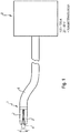
- FIG. 1 schematically illustrated surgical implant - cutting instrument of Bipolaarauart has a distal instrument head or instrument tip 1 with (at least) two instrument branches 2, which define a longitudinal longitudinal gap 4 extending in the instrument longitudinal direction between them.
- the instrument head 1 is mounted on a distal end of a preferably flexurally flexible (or even rigid), at least 2-pole instrument shaft 6, which in turn is connected to a controlled / regulated or controllable DC generator 8.
- the DC generator 8 supplies a DC current of preferably between 100A-150A at a voltage of preferably 20V-40V.
- the gap forming between the instrument branches 2 essentially has a V-shape which tapers in the proximal direction.
- the instrument shaft 6 and also the instrument head 1 have such an outer diameter (for example a maximum of 6 mm), which makes it possible for the surgical instrument to be insertable into the (standardized) working channel of a per se known endoscope, trocar or similar insertion aid.
- the instrument shaft and instrument head can be designed and dimensioned so that it can be inserted into a patient's hollow organ in the manner of a catheter (without insertion aid).
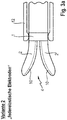
- the Fig. 2 shows in enlargement a variant of an inventive industry construction.
- the instrument industries 2 are firmly connected to the instrument head 1 and also rigid.
- electrically conductive electrodes 10 are arranged, which are connected via two current conductors (not shown) within the instrument shaft 6 to the DC generator 8.
- the branches 2 can themselves form the electrodes 10, for which, however, they must be fixed electrically insulated on the instrument head 1.
- the instrument industries 2 may also be equipped / populated with external electrodes 10.
- the design / arrangement of the electrodes 10 and their connection to the DC generator is the same for all variants described below, so that it is not described in a repetitive manner.
- the branches 2 and / or the electrodes 10 are made of a flexurally flexible, preferably elastic material, or the electrodes 10 are resiliently mounted on the respective instrument branches 2 such that they can be elastically pressed into the branches 2 by enlarging the gap width.
- an outer sleeve 12 is provided, which is axially movable relative to the instrument.
- This sleeve 12 may be a separate component or the insertion aid itself.
- the instrument is shown in a position in which the instrument head 1, but at least the instrument industries 2 protrude axially from the sleeve 12 and thereby radially (elastically) spread, causing the cutting gap 4 expands.
- the sleeve 12 may be formed at its distal end with an inner ring or bead 14 which engages with the instrument head 1 and the instrument branches 2 in sliding engagement with guide quality.
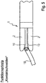
- Fig. 5 is shown a third variant of a branch construction.
- the branches 2 per se are preferably rigid, but pivotally mounted on the instrument head 1 (scissor-like).
- an actuating or adjusting device in the form of a pull / push rod 16 is provided, which is connected to the Branches 2 is articulated to transform an axial movement of the rod 16 in a pivoting movement of the branches 2. In this way, the cutting gap between the branches 2 can be adjusted.
- Fig. 5 shows the instrument with instrument branches 2, which are folded by the adjuster to define a minimum gap width.
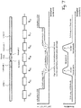
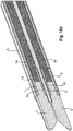
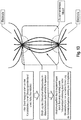
- Fig. 7 is the principle of operation of the DC-powered implant cutting instrument of the bipolar type according to the invention shown.
- the instrument industries 2 are basically spaced or spaced such that the longitudinally forming cutting gap 4 has a gap width, which is an insertion of an implant or implant portion 18 (stent wire) into the gap 4 under with two opposing longitudinal - branches 2 or Electrode 10 enables / ensures.
- the instrument industries 2 are preferably rounded in a banana-shaped / convex manner, at least in the region of their distal (free) end sections, in order to form a convex longitudinal curve at least along the sections facing one another.
- the cutting gap 4 does not taper (necessarily) linearly but along a curve. It is obvious that the electrodes 10 are adapted to this curve.
- the implant material usually comes into contact with the respective electrodes 10 already at the distal end section of the instrument branches 2 and closes them briefly, as a result of the applied current between the electrodes 10 heated implant material is heated and melted.
- the implant 18 slides deeper and deeper into the tapered cutting gap 4, the electrodes 10 preferably also dividing the melted implant material.
- the instrument industries 2 and / or at least the electrodes 10 according to a preferred embodiment of the invention, a kind of blade shape with a narrow (sharp) longitudinal edge on the respectively facing longitudinal side of each industry 2.
- This form is a (essentially one-dimensional) reaches point-like contact with the implant, which at this point the contact resistance and thus the current density and the material heating generated thereby is particularly high at DC application.
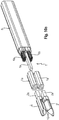
- a preferred construction for an inventive instrument industry 2 and / or electrode is in the FIGS. 10a ff. represented.
- the instrument industry 2 and the electrode 10 is integrally formed, ie, the instrument industry 2 also simultaneously forms the electrode 10.
- the instrument industry 2 is made of a refractory material, preferably tungsten or a low alloy steel.
- Each industry 2 is formed at its proximal end portion to a kind of hollow pin 2 a, according to the Fig. 10e in a corresponding receptacle socket / receiving sleeve 1 a is inserted on the side of the instrument head 1. Accordingly, two receptacles 1 a are provided for the two industries 2, which according to the FIG. 10e are separated from each other by an insulating / Diastanz Culture 1 b of the instrument head 1.
- each branch 2 is formed into a blade shape (ground / milled) with a part-circular blade back 2b and a longitudinally banana-shaped curved blade edge 2c.
- the blade shape can also be designed such that two (longitudinally) longitudinal sections which are at an obtuse angle to one another are provided, whereby the banana shape is approximated while forming a singular bend.
- a narrow (sharp) longitudinal edge / cutting edge 2e is formed, which extends arcuately in the sector longitudinal direction (corresponds to the instrument longitudinal direction).
- each instrument sector 2 or electrode 10 receives electrical contact with a respective conductor bundle 6a, 6b, which in turn are connected to the DC generator.
- the conductor bundles 6a, 6b despite low max. Shaft outside diameter obtained a comparatively large conductor thickness to conduct a sufficient electric current at a comparatively low current density (without warming).
- Each sector 2 forms the one cutting edge 2e, which at the same time also defines the contact line with the implant 18 and thus generates a high contact resistance (and thus high current density).
- the cutting edge 2e preferably serves for mechanically dividing the implant material which has been melted electrically.
- the surgical instrument has a contact quality detection function, as described below with reference to FIG Fig. 6-9 will be described in more detail.
- the contact grip between the instrument and the implant is shown functionally.
- an electrical current is conducted via the copper lines 6a, 6b in the instrument shaft 6 to the instrument branches 2 and from there via the point contact into the implant section between the branches.
- this achieves a high contact resistance.
- the implant 18 is not clamped exactly between the contact edges 2e of the instrument branches 2 or electrodes but rests on the electrode of each branch 2 over a large area.
- the contact resistance between the electrode and the implant would be significantly reduced (current density decreases), so that much more current would have to be conducted in the conductors 6a, 6b in order to achieve a melting of the implant material. This should be avoided in order to prevent the entire implant from heating up.
- nickel titanium in the ratio 39 to 4.86 (about 8x) can melt faster than unalloyed steel, and nickel titanium melt correspondingly faster in a ratio of 210 to 4.86 (about 43x) leaves as copper.
- material selection based on the resistance-adjusted specific melting energy, it is technically possible to meter a DC electrical current that flows through both the conductor, the electrode and the stent material so that it selectively melts the stent material, while the electrodes and the conductor does not reach the melting temperature during the current pulse.
- the materials are selected so that the resistivity-adjusted specific melt energy of the materials that are not to be melted (in particular, conductor material and electrode material) is at least twice the resistance-adjusted specific melt energy of those materials that are to be melted (especially the material of the implant to be cut).
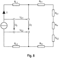
- the resistance profile along the electrical path is in Fig. 7 marked below.
- the two contact points represent resistance peaks, whereas the current in the remaining path sections is conducted virtually lossless.
- the invention provides for the execution of a test sequence, which is executed automatically with each new intervention either automatically or on manual command and in the Fig. 8 is shown schematically.
- the individual line sections of the electrical path form individually determinable resistors, of which only the contact resistances R K1, 2 are of interest at first.
- the conduction path is composed of the conductor bundles 6a, 6b in the instrument shaft 6, the branches 2, the contact points and the implant 18.
- a small test current is applied to the electrical path below the later cutting current, for example Reference voltage tapped directly at the distal end of the conductor bundles 6a, 6b. From the difference between the applied and tapped voltage of the conductor bundle resistance can be calculated.
- the contact quality detection function is able to give a warning signal for a faulty grip position and / or the supply of a Blocking current and / or to correct the height of the cutting current below the load limit of the conductor bundles 6a, 6b.
- the cutting / power current itself can be used for test purposes, in which case the cutting current may be applied for only a short time in order to keep the energy input into the implant smaller than that Energy input that would be required for a melting of the implant material.
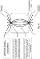
- Fig. 9 For the subsequent sheath according to Fig. 9 is one for implementing the principle of operation according to the Fig. 8 suitable circuit (see Fig. 9 ) is actuated to switch off the initially applied test current / power sequence and to replace it with a power current (cutting current) which, as shown, can be regulated at least as a function of the determined contact resistance R K1, 2 . Furthermore, factors such as the cutting temperature, the voltage level, the temperature in the conductor bundle, etc. may be incorporated into the cutting current setting procedure. Possibly. For example, an "emergency off" function may be provided which shuts off the power supply in the event of a contact abort on the electrodes, for example, to avoid arcing.
- the crystal lattice of a metal has a characteristic thermal energy, which manifests itself in vibrations of the atoms of the lattice. Thermal energy is thus a kinetic energy.
- the outflow of thermal energy into the environment has a strong dependence on the pulse duration ⁇ t according to the above connection. That is, the shorter the pulse, the less thermal energy flows.
- the bipolar cutting instrument produces the strongest possible local heating of a gripped piece of metal (with the target point of local melting) with the lowest possible entry of electrical energy. Although the gripped target metal should be melted, the instrument material should remain intact and the surrounding tissue should not be damaged.
- unalloyed steel is particularly well suited as an electrode material for cutting nickel-titanium, since this measure (the specific melt energy adjusted by the resistance factor) for unalloyed steel is significantly higher at 39 than for nickel-titanium at 4.86 (last column in Fig. 14 ). In other words, if both materials flow through the same current, Nickel-Titanium melts at 39 to 4.86 faster than unalloyed steel.
- a DC powered bipolar surgical implant cutting instrument having an instrument head at the distal end of a instrument shaft for minimally invasive insertion of the instrument into a patient's body, with at least two opposing instrumental arrays, preferably of the linear type, having a cutting gap therebetween at the instrument head define for receiving therebetween an electrically conductive implant or implant portion.
- electrodes are formed on their mutually facing longitudinal sides of the industry or are each equipped with at least one electrode, which in turn are each formed on their mutually facing longitudinal sides to form a cutting edge, by a punctiform physical contact engagement with the electrically conductive implant or implant section for an electrical short circuit of the opposing ones To effect electrodes.
- contact quality is understood to mean the framework conditions set for current density and current path length which result when the implant material is contacted with the instrument. Influencing factors can be, for example, the specific shape of the gripped / contacted implant section. If the gripped / contacted implant section between the electrodes is thin and flat, the result is a low current density; if it is rather narrow, a high current density results. The concrete contacting situation can be individually very different, resulting in different contact qualities. To ensure reliable cutting and at the same time excessive To avoid energy input (which can lead to deflagration effects or damage the instrument), it is useful to adjust the current intensity and pulse duration or shape according to the contact quality.
- the contact quality is determined according to the principle of four-wire measurement. This has application before the actual cutting process to determine suitable cutting parameters (current, pulse duration and shape), as well as during the cutting process.
- suitable cutting parameters current, pulse duration and shape
- the basic principle is in Fig. 8 shown.
- a small test current is introduced into the instrument before the cutting process in such a way that the test current flows through the electrodes through the stent material to be cut. Via two leads which make electrical contact with the electrodes, but through which the test current does not flow, the voltage drop U T generated by the test current can be measured between the two electrodes.
- the test current is well below the power current, preferably in the milliampere range (eg 20 mA). In addition to the determination of the contact quality, it is thus also possible to determine whether an electrically conductive contact has actually been produced.
- the contact quality determination is before the cutting process (preferably when a stable electrical contact detected was) sent a test pulse through the implant material to be cut, which leads to a warming but not to melting. Heating leads to an increase in the specific resistance of the material and consequently to an increase in the voltage U T between the electrodes, which is determined according to the principle of the four-wire method.
- this pulse it is possible by means of the increase curve of the electrical resistance between the electrode (corresponding to the resistances R E1 , R K1 , R M , R K2 and R E2 in the equivalent circuit diagram) to derive a prognosis of the energy input required for the melting. This can serve as the basis for setting the cutting parameters.
- During the cutting process can be monitored from the monitoring of the voltage U T between the electrodes of the cutting process with the aim to adjust if necessary, the cutting parameters so that, for example, a foreseeable set too low parameter is corrected.
- the voltages U L1 and U L2 are determined. This is done both with the test current before the cutting process and with the power current during the cutting process. Since the ohmic resistance of the conductor material changes with temperature, the measurement of the voltage drop at a known current of the ohmic resistance and thus the temperature can be determined. This is particularly useful to detect overheating of the instrument shaft and to avoid by appropriate adjustment of the cutting parameters or termination of the cutting process.
- the temperature coefficient of various conductive materials is in Fig. 14 shown.
- test current is preferably many times smaller than the power current, it is expedient to be able to selectively amplify the measurement of the voltages U T , U L1 and U L2 electronically.
- a simplified corresponding circuit is in Fig. 9 shown.
Landscapes
- Health & Medical Sciences (AREA)
- Surgery (AREA)
- Engineering & Computer Science (AREA)
- Life Sciences & Earth Sciences (AREA)
- Biomedical Technology (AREA)
- Otolaryngology (AREA)
- Nuclear Medicine, Radiotherapy & Molecular Imaging (AREA)
- Plasma & Fusion (AREA)
- Physics & Mathematics (AREA)
- Heart & Thoracic Surgery (AREA)
- Medical Informatics (AREA)
- Molecular Biology (AREA)
- Animal Behavior & Ethology (AREA)
- General Health & Medical Sciences (AREA)
- Public Health (AREA)
- Veterinary Medicine (AREA)
- Surgical Instruments (AREA)
Applications Claiming Priority (2)
| Application Number | Priority Date | Filing Date | Title |
|---|---|---|---|
| DE102013102418.1A DE102013102418A1 (de) | 2013-03-11 | 2013-03-11 | Chirurgischer Gleichstromschneider |
| PCT/EP2014/054740 WO2014140039A1 (de) | 2013-03-11 | 2014-03-11 | Chirurgischer gleichstromschneider |
Publications (2)
| Publication Number | Publication Date |
|---|---|
| EP2967712A1 EP2967712A1 (de) | 2016-01-20 |
| EP2967712B1 true EP2967712B1 (de) | 2017-03-08 |
Family
ID=50241439
Family Applications (1)
| Application Number | Title | Priority Date | Filing Date |
|---|---|---|---|
| EP14709301.7A Active EP2967712B1 (de) | 2013-03-11 | 2014-03-11 | Chirurgischer gleichstromschneider |
Country Status (6)
Families Citing this family (7)
| Publication number | Priority date | Publication date | Assignee | Title |
|---|---|---|---|---|
| EP3243452B1 (en) * | 2016-05-11 | 2018-11-14 | Ovesco Endoscopy AG | Medical dc current generator and bipolar medical implant fragmentation device equipped therewith |
| CA2997873A1 (en) * | 2017-03-08 | 2018-09-08 | Memic Innovative Surgery Ltd. | Electrosurgery device |
| US11350977B2 (en) | 2017-03-08 | 2022-06-07 | Memic Innovative Surgery Ltd. | Modular electrosurgical device |
| DE202018101753U1 (de) | 2018-03-28 | 2018-05-08 | Tuebingen Scientific Medical Gmbh | Elektroden-Applikationsinstrument |
| USD888950S1 (en) * | 2018-10-10 | 2020-06-30 | Bolder Surgical, Llc | Yoke assembly for a surgical instrument |
| CN112168343B (zh) * | 2020-10-09 | 2023-05-16 | 杭州埃杜医疗科技有限公司 | 一次性射频等离子手术电极 |
| WO2022094087A1 (en) * | 2020-10-28 | 2022-05-05 | United States Endoscopy Group, Inc. | Cap for endoscope |
Citations (1)
| Publication number | Priority date | Publication date | Assignee | Title |
|---|---|---|---|---|
| US3354478A (en) * | 1965-10-22 | 1967-11-28 | Ingersoll Rand Co | Wire cutting and connecting tool |
Family Cites Families (11)
| Publication number | Priority date | Publication date | Assignee | Title |
|---|---|---|---|---|
| US3431384A (en) * | 1965-09-24 | 1969-03-04 | Sperry Rand Corp | Means for cutting wire by wire-melting electrical pulses |
| US6736813B2 (en) * | 1998-01-23 | 2004-05-18 | Olympus Optical Co., Ltd. | High-frequency treatment tool |
| JP4783790B2 (ja) * | 2005-08-18 | 2011-09-28 | オリンパスメディカルシステムズ株式会社 | バイポーラカッター |
| DE102005053764B4 (de) * | 2005-11-10 | 2012-01-19 | Günter Farin | Instrument zur endoskopisch kontrollierten Kürzung und/oder Fragmentierung von Stents |
| US20080015575A1 (en) * | 2006-07-14 | 2008-01-17 | Sherwood Services Ag | Vessel sealing instrument with pre-heated electrodes |
| ATE538736T1 (de) * | 2006-10-05 | 2012-01-15 | Erbe Elektromedizin | Medizinisches instrument |
| DE102007003838A1 (de) * | 2007-01-25 | 2008-08-07 | Erbe Elektromedizin Gmbh | Bipolares Instrument und Verfahren zur endoskopisch kontrollierten Kürzung und/oder Fragmentierung von im Gastrointestinaltrakt, im Tracheobronchialsystem oder in anderen Hohlorganen befindlichen Stents |
| US9168054B2 (en) * | 2009-10-09 | 2015-10-27 | Ethicon Endo-Surgery, Inc. | Surgical generator for ultrasonic and electrosurgical devices |
| US8540749B2 (en) * | 2010-06-02 | 2013-09-24 | Covidien Lp | Apparatus for performing an electrosurgical procedure |
| US9089327B2 (en) | 2010-09-24 | 2015-07-28 | Ethicon Endo-Surgery, Inc. | Surgical instrument with multi-phase trigger bias |
| US9226767B2 (en) * | 2012-06-29 | 2016-01-05 | Ethicon Endo-Surgery, Inc. | Closed feedback control for electrosurgical device |
-
2013
- 2013-03-11 DE DE102013102418.1A patent/DE102013102418A1/de not_active Withdrawn
-
2014
- 2014-03-11 ES ES14709301.7T patent/ES2628101T3/es active Active
- 2014-03-11 JP JP2015562097A patent/JP6194026B2/ja active Active
- 2014-03-11 US US14/774,694 patent/US10881454B2/en active Active
- 2014-03-11 EP EP14709301.7A patent/EP2967712B1/de active Active
- 2014-03-11 WO PCT/EP2014/054740 patent/WO2014140039A1/de active Application Filing
Patent Citations (1)
| Publication number | Priority date | Publication date | Assignee | Title |
|---|---|---|---|---|
| US3354478A (en) * | 1965-10-22 | 1967-11-28 | Ingersoll Rand Co | Wire cutting and connecting tool |
Also Published As
| Publication number | Publication date |
|---|---|
| DE102013102418A1 (de) | 2014-09-11 |
| WO2014140039A1 (de) | 2014-09-18 |
| US20160022356A1 (en) | 2016-01-28 |
| US10881454B2 (en) | 2021-01-05 |
| EP2967712A1 (de) | 2016-01-20 |
| JP2016509908A (ja) | 2016-04-04 |
| JP6194026B2 (ja) | 2017-09-06 |
| ES2628101T3 (es) | 2017-08-01 |
Similar Documents
| Publication | Publication Date | Title |
|---|---|---|
| EP2967712B1 (de) | Chirurgischer gleichstromschneider | |
| DE2513868C2 (de) | Bipolare Elektrodiathermiefaßzange | |
| DE69927411T2 (de) | Ein elektrochirurgisches gerät zum koagulieren und schneiden, eine methode zum trennen von blutgefässen und eine methode zur koagulation und zum schneiden in oder trennen von gewebe | |
| DE60312873T2 (de) | Elektrochirurgisches instrument zum verschluss von gefässen | |
| DE69831693T2 (de) | Ein elektrochirurgisches gerät zur koagulation und zum schneiden | |
| DE602005004637T2 (de) | Zange mit federbelastetem Greiforgan | |
| EP1527743B1 (de) | Medizingerät für die Elektrotomie | |
| EP2044900B1 (de) | Elektrochirurgisches Instrument | |
| DE69232781T2 (de) | Elektrochirurgisches schneidwerkzeug | |
| DE69110794T2 (de) | Katheter zur Ablation. | |
| EP2077774B1 (de) | Rohrschaftinstrument | |
| DE69432050T2 (de) | Elektrochirurgisches impedanzrückkopplungssystem | |
| DE69833505T2 (de) | Bipolares elektrochirurgisches instrument zum verschliessen von gefässen | |
| DE10030111B4 (de) | Sondenelektrode | |
| EP2243437B1 (de) | Hysterektomlegerät mit Uterusmanipulator | |
| DE60015731T2 (de) | Chirurgisches biopsieinstrument | |
| DE20002645U1 (de) | Medizinisches bipolares Instrument zum Schneiden von Gewebe | |
| WO2001022896A1 (de) | Medizinisches bipolares instrument zum schneiden von gewebe | |
| EP2679186B1 (de) | Instrument zur Gefäßfusion und -trennung | |
| EP2124846A1 (de) | Bipolares instrument und verfahren zur endoskopisch kontrollierten kürzung und/oder fragmentierung von im gastrointestinaltrakt, im tracheobronchialsystem oder in anderen hohlorganen befindlichen stents | |
| EP1945136A2 (de) | Instrument und verfahren zur endoskopisch kontrollierten kürzung und/oder fragmentierung von in hohlorganen befindlichen stents | |
| DE69828988T2 (de) | Elektochirurgische elektrode ein elektrisches feld konzentrierend | |
| AT411013B (de) | Venenstripper | |
| EP2554133A1 (de) | Instrument zur Gefäßfusion und -trennung mit zwei Branchen und einer gekrümmten Elektrode | |
| DE19858375B4 (de) | Einrichtung zur HF-Koagulation biologischer Gewebe mittels flexibler Endoskopie |
Legal Events
| Date | Code | Title | Description |
|---|---|---|---|
| PUAI | Public reference made under article 153(3) epc to a published international application that has entered the european phase |
Free format text: ORIGINAL CODE: 0009012 |
|
| 17P | Request for examination filed |
Effective date: 20150921 |
|
| AK | Designated contracting states |
Kind code of ref document: A1 Designated state(s): AL AT BE BG CH CY CZ DE DK EE ES FI FR GB GR HR HU IE IS IT LI LT LU LV MC MK MT NL NO PL PT RO RS SE SI SK SM TR |
|
| AX | Request for extension of the european patent |
Extension state: BA ME |
|
| 17Q | First examination report despatched |
Effective date: 20160122 |
|
| RIN1 | Information on inventor provided before grant (corrected) |
Inventor name: HO, CHI-NGHIA Inventor name: MELBERT, MICHAEL Inventor name: GOTTWALD, THOMAS Inventor name: SCHURR, MARC O. Inventor name: SCHOSTEK, SEBASTIAN |
|
| DAX | Request for extension of the european patent (deleted) | ||
| GRAP | Despatch of communication of intention to grant a patent |
Free format text: ORIGINAL CODE: EPIDOSNIGR1 |
|
| INTG | Intention to grant announced |
Effective date: 20160909 |
|
| GRAS | Grant fee paid |
Free format text: ORIGINAL CODE: EPIDOSNIGR3 |
|
| GRAA | (expected) grant |
Free format text: ORIGINAL CODE: 0009210 |
|
| AK | Designated contracting states |
Kind code of ref document: B1 Designated state(s): AL AT BE BG CH CY CZ DE DK EE ES FI FR GB GR HR HU IE IS IT LI LT LU LV MC MK MT NL NO PL PT RO RS SE SI SK SM TR |
|
| REG | Reference to a national code |
Ref country code: GB Ref legal event code: FG4D Free format text: NOT ENGLISH |
|
| REG | Reference to a national code |
Ref country code: CH Ref legal event code: EP Ref country code: AT Ref legal event code: REF Ref document number: 872823 Country of ref document: AT Kind code of ref document: T Effective date: 20170315 |
|
| REG | Reference to a national code |
Ref country code: IE Ref legal event code: FG4D Free format text: LANGUAGE OF EP DOCUMENT: GERMAN |
|
| REG | Reference to a national code |
Ref country code: DE Ref legal event code: R096 Ref document number: 502014002929 Country of ref document: DE |
|
| REG | Reference to a national code |
Ref country code: FR Ref legal event code: PLFP Year of fee payment: 4 |
|
| REG | Reference to a national code |
Ref country code: LT Ref legal event code: MG4D |
|
| REG | Reference to a national code |
Ref country code: NL Ref legal event code: MP Effective date: 20170308 |
|
| PG25 | Lapsed in a contracting state [announced via postgrant information from national office to epo] |
Ref country code: LT Free format text: LAPSE BECAUSE OF FAILURE TO SUBMIT A TRANSLATION OF THE DESCRIPTION OR TO PAY THE FEE WITHIN THE PRESCRIBED TIME-LIMIT Effective date: 20170308 Ref country code: NO Free format text: LAPSE BECAUSE OF FAILURE TO SUBMIT A TRANSLATION OF THE DESCRIPTION OR TO PAY THE FEE WITHIN THE PRESCRIBED TIME-LIMIT Effective date: 20170608 Ref country code: HR Free format text: LAPSE BECAUSE OF FAILURE TO SUBMIT A TRANSLATION OF THE DESCRIPTION OR TO PAY THE FEE WITHIN THE PRESCRIBED TIME-LIMIT Effective date: 20170308 Ref country code: GR Free format text: LAPSE BECAUSE OF FAILURE TO SUBMIT A TRANSLATION OF THE DESCRIPTION OR TO PAY THE FEE WITHIN THE PRESCRIBED TIME-LIMIT Effective date: 20170609 Ref country code: FI Free format text: LAPSE BECAUSE OF FAILURE TO SUBMIT A TRANSLATION OF THE DESCRIPTION OR TO PAY THE FEE WITHIN THE PRESCRIBED TIME-LIMIT Effective date: 20170308 |
|
| REG | Reference to a national code |
Ref country code: ES Ref legal event code: FG2A Ref document number: 2628101 Country of ref document: ES Kind code of ref document: T3 Effective date: 20170801 |
|
| PG25 | Lapsed in a contracting state [announced via postgrant information from national office to epo] |
Ref country code: BG Free format text: LAPSE BECAUSE OF FAILURE TO SUBMIT A TRANSLATION OF THE DESCRIPTION OR TO PAY THE FEE WITHIN THE PRESCRIBED TIME-LIMIT Effective date: 20170608 Ref country code: SE Free format text: LAPSE BECAUSE OF FAILURE TO SUBMIT A TRANSLATION OF THE DESCRIPTION OR TO PAY THE FEE WITHIN THE PRESCRIBED TIME-LIMIT Effective date: 20170308 Ref country code: LV Free format text: LAPSE BECAUSE OF FAILURE TO SUBMIT A TRANSLATION OF THE DESCRIPTION OR TO PAY THE FEE WITHIN THE PRESCRIBED TIME-LIMIT Effective date: 20170308 Ref country code: RS Free format text: LAPSE BECAUSE OF FAILURE TO SUBMIT A TRANSLATION OF THE DESCRIPTION OR TO PAY THE FEE WITHIN THE PRESCRIBED TIME-LIMIT Effective date: 20170308 |
|
| PG25 | Lapsed in a contracting state [announced via postgrant information from national office to epo] |
Ref country code: NL Free format text: LAPSE BECAUSE OF FAILURE TO SUBMIT A TRANSLATION OF THE DESCRIPTION OR TO PAY THE FEE WITHIN THE PRESCRIBED TIME-LIMIT Effective date: 20170308 |
|
| PG25 | Lapsed in a contracting state [announced via postgrant information from national office to epo] |
Ref country code: CZ Free format text: LAPSE BECAUSE OF FAILURE TO SUBMIT A TRANSLATION OF THE DESCRIPTION OR TO PAY THE FEE WITHIN THE PRESCRIBED TIME-LIMIT Effective date: 20170308 Ref country code: RO Free format text: LAPSE BECAUSE OF FAILURE TO SUBMIT A TRANSLATION OF THE DESCRIPTION OR TO PAY THE FEE WITHIN THE PRESCRIBED TIME-LIMIT Effective date: 20170308 Ref country code: EE Free format text: LAPSE BECAUSE OF FAILURE TO SUBMIT A TRANSLATION OF THE DESCRIPTION OR TO PAY THE FEE WITHIN THE PRESCRIBED TIME-LIMIT Effective date: 20170308 Ref country code: SK Free format text: LAPSE BECAUSE OF FAILURE TO SUBMIT A TRANSLATION OF THE DESCRIPTION OR TO PAY THE FEE WITHIN THE PRESCRIBED TIME-LIMIT Effective date: 20170308 |
|
| REG | Reference to a national code |
Ref country code: CH Ref legal event code: PL |
|
| PG25 | Lapsed in a contracting state [announced via postgrant information from national office to epo] |
Ref country code: PL Free format text: LAPSE BECAUSE OF FAILURE TO SUBMIT A TRANSLATION OF THE DESCRIPTION OR TO PAY THE FEE WITHIN THE PRESCRIBED TIME-LIMIT Effective date: 20170308 Ref country code: PT Free format text: LAPSE BECAUSE OF FAILURE TO SUBMIT A TRANSLATION OF THE DESCRIPTION OR TO PAY THE FEE WITHIN THE PRESCRIBED TIME-LIMIT Effective date: 20170710 Ref country code: IS Free format text: LAPSE BECAUSE OF FAILURE TO SUBMIT A TRANSLATION OF THE DESCRIPTION OR TO PAY THE FEE WITHIN THE PRESCRIBED TIME-LIMIT Effective date: 20170708 Ref country code: SM Free format text: LAPSE BECAUSE OF FAILURE TO SUBMIT A TRANSLATION OF THE DESCRIPTION OR TO PAY THE FEE WITHIN THE PRESCRIBED TIME-LIMIT Effective date: 20170308 |
|
| REG | Reference to a national code |
Ref country code: DE Ref legal event code: R097 Ref document number: 502014002929 Country of ref document: DE |
|
| REG | Reference to a national code |
Ref country code: IE Ref legal event code: MM4A |
|
| PLBE | No opposition filed within time limit |
Free format text: ORIGINAL CODE: 0009261 |
|
| STAA | Information on the status of an ep patent application or granted ep patent |
Free format text: STATUS: NO OPPOSITION FILED WITHIN TIME LIMIT |
|
| PG25 | Lapsed in a contracting state [announced via postgrant information from national office to epo] |
Ref country code: DK Free format text: LAPSE BECAUSE OF FAILURE TO SUBMIT A TRANSLATION OF THE DESCRIPTION OR TO PAY THE FEE WITHIN THE PRESCRIBED TIME-LIMIT Effective date: 20170308 Ref country code: LU Free format text: LAPSE BECAUSE OF NON-PAYMENT OF DUE FEES Effective date: 20170311 Ref country code: MC Free format text: LAPSE BECAUSE OF FAILURE TO SUBMIT A TRANSLATION OF THE DESCRIPTION OR TO PAY THE FEE WITHIN THE PRESCRIBED TIME-LIMIT Effective date: 20170308 |
|
| 26N | No opposition filed |
Effective date: 20171211 |
|
| PG25 | Lapsed in a contracting state [announced via postgrant information from national office to epo] |
Ref country code: SI Free format text: LAPSE BECAUSE OF FAILURE TO SUBMIT A TRANSLATION OF THE DESCRIPTION OR TO PAY THE FEE WITHIN THE PRESCRIBED TIME-LIMIT Effective date: 20170308 Ref country code: CH Free format text: LAPSE BECAUSE OF NON-PAYMENT OF DUE FEES Effective date: 20170331 Ref country code: LI Free format text: LAPSE BECAUSE OF NON-PAYMENT OF DUE FEES Effective date: 20170331 Ref country code: IE Free format text: LAPSE BECAUSE OF NON-PAYMENT OF DUE FEES Effective date: 20170311 |
|
| REG | Reference to a national code |
Ref country code: BE Ref legal event code: MM Effective date: 20170331 |
|
| REG | Reference to a national code |
Ref country code: FR Ref legal event code: PLFP Year of fee payment: 5 |
|
| PG25 | Lapsed in a contracting state [announced via postgrant information from national office to epo] |
Ref country code: BE Free format text: LAPSE BECAUSE OF NON-PAYMENT OF DUE FEES Effective date: 20170331 |
|
| PG25 | Lapsed in a contracting state [announced via postgrant information from national office to epo] |
Ref country code: MT Free format text: LAPSE BECAUSE OF FAILURE TO SUBMIT A TRANSLATION OF THE DESCRIPTION OR TO PAY THE FEE WITHIN THE PRESCRIBED TIME-LIMIT Effective date: 20170308 |
|
| PG25 | Lapsed in a contracting state [announced via postgrant information from national office to epo] |
Ref country code: HU Free format text: LAPSE BECAUSE OF FAILURE TO SUBMIT A TRANSLATION OF THE DESCRIPTION OR TO PAY THE FEE WITHIN THE PRESCRIBED TIME-LIMIT; INVALID AB INITIO Effective date: 20140311 |
|
| PG25 | Lapsed in a contracting state [announced via postgrant information from national office to epo] |
Ref country code: CY Free format text: LAPSE BECAUSE OF FAILURE TO SUBMIT A TRANSLATION OF THE DESCRIPTION OR TO PAY THE FEE WITHIN THE PRESCRIBED TIME-LIMIT Effective date: 20170308 |
|
| PG25 | Lapsed in a contracting state [announced via postgrant information from national office to epo] |
Ref country code: MK Free format text: LAPSE BECAUSE OF FAILURE TO SUBMIT A TRANSLATION OF THE DESCRIPTION OR TO PAY THE FEE WITHIN THE PRESCRIBED TIME-LIMIT Effective date: 20170308 |
|
| PG25 | Lapsed in a contracting state [announced via postgrant information from national office to epo] |
Ref country code: TR Free format text: LAPSE BECAUSE OF FAILURE TO SUBMIT A TRANSLATION OF THE DESCRIPTION OR TO PAY THE FEE WITHIN THE PRESCRIBED TIME-LIMIT Effective date: 20170308 |
|
| PG25 | Lapsed in a contracting state [announced via postgrant information from national office to epo] |
Ref country code: AL Free format text: LAPSE BECAUSE OF FAILURE TO SUBMIT A TRANSLATION OF THE DESCRIPTION OR TO PAY THE FEE WITHIN THE PRESCRIBED TIME-LIMIT Effective date: 20170308 |
|
| REG | Reference to a national code |
Ref country code: AT Ref legal event code: MM01 Ref document number: 872823 Country of ref document: AT Kind code of ref document: T Effective date: 20190311 |
|
| PG25 | Lapsed in a contracting state [announced via postgrant information from national office to epo] |
Ref country code: AT Free format text: LAPSE BECAUSE OF NON-PAYMENT OF DUE FEES Effective date: 20190311 |
|
| P01 | Opt-out of the competence of the unified patent court (upc) registered |
Effective date: 20230512 |
|
| PGFP | Annual fee paid to national office [announced via postgrant information from national office to epo] |
Ref country code: DE Payment date: 20250214 Year of fee payment: 12 |
|
| PGFP | Annual fee paid to national office [announced via postgrant information from national office to epo] |
Ref country code: FR Payment date: 20250324 Year of fee payment: 12 |
|
| PGFP | Annual fee paid to national office [announced via postgrant information from national office to epo] |
Ref country code: GB Payment date: 20250324 Year of fee payment: 12 |
|
| PGFP | Annual fee paid to national office [announced via postgrant information from national office to epo] |
Ref country code: ES Payment date: 20250416 Year of fee payment: 12 |
|
| PGFP | Annual fee paid to national office [announced via postgrant information from national office to epo] |
Ref country code: IT Payment date: 20250331 Year of fee payment: 12 |