US10881454B2 - Surgical cutter operated with direct current - Google Patents
Surgical cutter operated with direct current Download PDFInfo
- Publication number
- US10881454B2 US10881454B2 US14/774,694 US201414774694A US10881454B2 US 10881454 B2 US10881454 B2 US 10881454B2 US 201414774694 A US201414774694 A US 201414774694A US 10881454 B2 US10881454 B2 US 10881454B2
- Authority
- US
- United States
- Prior art keywords
- implant
- cutting
- electrodes
- instrument
- current
- Prior art date
- Legal status (The legal status is an assumption and is not a legal conclusion. Google has not performed a legal analysis and makes no representation as to the accuracy of the status listed.)
- Active, expires
Links
- 238000005520 cutting process Methods 0.000 claims abstract description 121
- 239000007943 implant Substances 0.000 claims abstract description 108
- 230000000694 effects Effects 0.000 claims abstract description 9
- 239000000463 material Substances 0.000 claims description 94
- 238000002844 melting Methods 0.000 claims description 34
- 230000008018 melting Effects 0.000 claims description 34
- 238000012360 testing method Methods 0.000 claims description 28
- 238000001514 detection method Methods 0.000 claims description 20
- 238000010438 heat treatment Methods 0.000 claims description 14
- 238000003780 insertion Methods 0.000 claims description 8
- 230000037431 insertion Effects 0.000 claims description 8
- 238000005259 measurement Methods 0.000 claims description 6
- 238000000034 method Methods 0.000 claims description 6
- 230000008569 process Effects 0.000 claims description 4
- 239000003779 heat-resistant material Substances 0.000 claims description 3
- 230000008859 change Effects 0.000 claims description 2
- 230000007246 mechanism Effects 0.000 claims description 2
- 239000004020 conductor Substances 0.000 description 28
- 229910052751 metal Inorganic materials 0.000 description 18
- 239000002184 metal Substances 0.000 description 18
- 238000010276 construction Methods 0.000 description 8
- 239000007772 electrode material Substances 0.000 description 8
- 210000000056 organ Anatomy 0.000 description 8
- 229910000831 Steel Inorganic materials 0.000 description 7
- HZEWFHLRYVTOIW-UHFFFAOYSA-N [Ti].[Ni] Chemical compound [Ti].[Ni] HZEWFHLRYVTOIW-UHFFFAOYSA-N 0.000 description 7
- 229910001000 nickel titanium Inorganic materials 0.000 description 7
- 239000010959 steel Substances 0.000 description 7
- 230000001419 dependent effect Effects 0.000 description 6
- 238000010891 electric arc Methods 0.000 description 6
- 239000000155 melt Substances 0.000 description 6
- RYGMFSIKBFXOCR-UHFFFAOYSA-N Copper Chemical compound [Cu] RYGMFSIKBFXOCR-UHFFFAOYSA-N 0.000 description 5
- 229910052802 copper Inorganic materials 0.000 description 5
- 239000010949 copper Substances 0.000 description 5
- 238000010586 diagram Methods 0.000 description 5
- 230000017525 heat dissipation Effects 0.000 description 5
- 230000006378 damage Effects 0.000 description 4
- 238000013461 design Methods 0.000 description 4
- 238000003466 welding Methods 0.000 description 4
- 206010016717 Fistula Diseases 0.000 description 3
- 230000003890 fistula Effects 0.000 description 3
- 230000007704 transition Effects 0.000 description 3
- WFKWXMTUELFFGS-UHFFFAOYSA-N tungsten Chemical compound [W] WFKWXMTUELFFGS-UHFFFAOYSA-N 0.000 description 3
- 229910000851 Alloy steel Inorganic materials 0.000 description 2
- 241000234295 Musa Species 0.000 description 2
- 235000018290 Musa x paradisiaca Nutrition 0.000 description 2
- 238000010521 absorption reaction Methods 0.000 description 2
- 230000015572 biosynthetic process Effects 0.000 description 2
- 230000035876 healing Effects 0.000 description 2
- 230000003902 lesion Effects 0.000 description 2
- 230000001681 protective effect Effects 0.000 description 2
- 230000009467 reduction Effects 0.000 description 2
- 238000000926 separation method Methods 0.000 description 2
- 241000894006 Bacteria Species 0.000 description 1
- 206010061218 Inflammation Diseases 0.000 description 1
- 229910001069 Ti alloy Inorganic materials 0.000 description 1
- 239000007875 V-40 Substances 0.000 description 1
- 238000004873 anchoring Methods 0.000 description 1
- 230000036760 body temperature Effects 0.000 description 1
- 239000002800 charge carrier Substances 0.000 description 1
- 238000005345 coagulation Methods 0.000 description 1
- 230000015271 coagulation Effects 0.000 description 1
- 238000007906 compression Methods 0.000 description 1
- 239000013078 crystal Substances 0.000 description 1
- 230000001079 digestive effect Effects 0.000 description 1
- 239000013013 elastic material Substances 0.000 description 1
- 238000001839 endoscopy Methods 0.000 description 1
- 238000005516 engineering process Methods 0.000 description 1
- 238000002474 experimental method Methods 0.000 description 1
- 238000004880 explosion Methods 0.000 description 1
- 238000009472 formulation Methods 0.000 description 1
- 238000013467 fragmentation Methods 0.000 description 1
- 238000006062 fragmentation reaction Methods 0.000 description 1
- 235000011389 fruit/vegetable juice Nutrition 0.000 description 1
- 230000004927 fusion Effects 0.000 description 1
- 210000001035 gastrointestinal tract Anatomy 0.000 description 1
- 230000004054 inflammatory process Effects 0.000 description 1
- 230000003993 interaction Effects 0.000 description 1
- 229910000734 martensite Inorganic materials 0.000 description 1
- 239000012528 membrane Substances 0.000 description 1
- 229910001092 metal group alloy Inorganic materials 0.000 description 1
- 150000002739 metals Chemical class 0.000 description 1
- 238000012544 monitoring process Methods 0.000 description 1
- 238000013021 overheating Methods 0.000 description 1
- 229920001296 polysiloxane Polymers 0.000 description 1
- 238000004393 prognosis Methods 0.000 description 1
- 238000011084 recovery Methods 0.000 description 1
- 239000000523 sample Substances 0.000 description 1
- 238000004904 shortening Methods 0.000 description 1
- 239000010935 stainless steel Substances 0.000 description 1
- 229910001220 stainless steel Inorganic materials 0.000 description 1
- 239000013077 target material Substances 0.000 description 1
- 238000002560 therapeutic procedure Methods 0.000 description 1
- 230000000451 tissue damage Effects 0.000 description 1
- 231100000827 tissue damage Toxicity 0.000 description 1
- 230000009466 transformation Effects 0.000 description 1
Images


Classifications
-
- A—HUMAN NECESSITIES
- A61—MEDICAL OR VETERINARY SCIENCE; HYGIENE
- A61B—DIAGNOSIS; SURGERY; IDENTIFICATION
- A61B18/00—Surgical instruments, devices or methods for transferring non-mechanical forms of energy to or from the body
- A61B18/04—Surgical instruments, devices or methods for transferring non-mechanical forms of energy to or from the body by heating
- A61B18/12—Surgical instruments, devices or methods for transferring non-mechanical forms of energy to or from the body by heating by passing a current through the tissue to be heated, e.g. high-frequency current
- A61B18/14—Probes or electrodes therefor
- A61B18/1442—Probes having pivoting end effectors, e.g. forceps
- A61B18/1445—Probes having pivoting end effectors, e.g. forceps at the distal end of a shaft, e.g. forceps or scissors at the end of a rigid rod
- A61B18/1447—Probes having pivoting end effectors, e.g. forceps at the distal end of a shaft, e.g. forceps or scissors at the end of a rigid rod wherein sliding surfaces cause opening/closing of the end effectors
-
- A—HUMAN NECESSITIES
- A61—MEDICAL OR VETERINARY SCIENCE; HYGIENE
- A61B—DIAGNOSIS; SURGERY; IDENTIFICATION
- A61B18/00—Surgical instruments, devices or methods for transferring non-mechanical forms of energy to or from the body
- A61B18/04—Surgical instruments, devices or methods for transferring non-mechanical forms of energy to or from the body by heating
- A61B18/12—Surgical instruments, devices or methods for transferring non-mechanical forms of energy to or from the body by heating by passing a current through the tissue to be heated, e.g. high-frequency current
- A61B18/14—Probes or electrodes therefor
- A61B18/1442—Probes having pivoting end effectors, e.g. forceps
- A61B18/1445—Probes having pivoting end effectors, e.g. forceps at the distal end of a shaft, e.g. forceps or scissors at the end of a rigid rod
-
- A—HUMAN NECESSITIES
- A61—MEDICAL OR VETERINARY SCIENCE; HYGIENE
- A61B—DIAGNOSIS; SURGERY; IDENTIFICATION
- A61B18/00—Surgical instruments, devices or methods for transferring non-mechanical forms of energy to or from the body
- A61B2018/00636—Sensing and controlling the application of energy
- A61B2018/00642—Sensing and controlling the application of energy with feedback, i.e. closed loop control
-
- A—HUMAN NECESSITIES
- A61—MEDICAL OR VETERINARY SCIENCE; HYGIENE
- A61B—DIAGNOSIS; SURGERY; IDENTIFICATION
- A61B18/00—Surgical instruments, devices or methods for transferring non-mechanical forms of energy to or from the body
- A61B2018/00636—Sensing and controlling the application of energy
- A61B2018/00666—Sensing and controlling the application of energy using a threshold value
- A61B2018/00672—Sensing and controlling the application of energy using a threshold value lower
-
- A—HUMAN NECESSITIES
- A61—MEDICAL OR VETERINARY SCIENCE; HYGIENE
- A61B—DIAGNOSIS; SURGERY; IDENTIFICATION
- A61B18/00—Surgical instruments, devices or methods for transferring non-mechanical forms of energy to or from the body
- A61B2018/00636—Sensing and controlling the application of energy
- A61B2018/00666—Sensing and controlling the application of energy using a threshold value
- A61B2018/00678—Sensing and controlling the application of energy using a threshold value upper
-
- A—HUMAN NECESSITIES
- A61—MEDICAL OR VETERINARY SCIENCE; HYGIENE
- A61B—DIAGNOSIS; SURGERY; IDENTIFICATION
- A61B18/00—Surgical instruments, devices or methods for transferring non-mechanical forms of energy to or from the body
- A61B2018/00636—Sensing and controlling the application of energy
- A61B2018/00696—Controlled or regulated parameters
- A61B2018/00702—Power or energy
-
- A—HUMAN NECESSITIES
- A61—MEDICAL OR VETERINARY SCIENCE; HYGIENE
- A61B—DIAGNOSIS; SURGERY; IDENTIFICATION
- A61B18/00—Surgical instruments, devices or methods for transferring non-mechanical forms of energy to or from the body
- A61B2018/00636—Sensing and controlling the application of energy
- A61B2018/00696—Controlled or regulated parameters
- A61B2018/00714—Temperature
-
- A—HUMAN NECESSITIES
- A61—MEDICAL OR VETERINARY SCIENCE; HYGIENE
- A61B—DIAGNOSIS; SURGERY; IDENTIFICATION
- A61B18/00—Surgical instruments, devices or methods for transferring non-mechanical forms of energy to or from the body
- A61B2018/00636—Sensing and controlling the application of energy
- A61B2018/00696—Controlled or regulated parameters
- A61B2018/0072—Current
-
- A—HUMAN NECESSITIES
- A61—MEDICAL OR VETERINARY SCIENCE; HYGIENE
- A61B—DIAGNOSIS; SURGERY; IDENTIFICATION
- A61B18/00—Surgical instruments, devices or methods for transferring non-mechanical forms of energy to or from the body
- A61B2018/00636—Sensing and controlling the application of energy
- A61B2018/00696—Controlled or regulated parameters
- A61B2018/00761—Duration
-
- A—HUMAN NECESSITIES
- A61—MEDICAL OR VETERINARY SCIENCE; HYGIENE
- A61B—DIAGNOSIS; SURGERY; IDENTIFICATION
- A61B18/00—Surgical instruments, devices or methods for transferring non-mechanical forms of energy to or from the body
- A61B2018/00636—Sensing and controlling the application of energy
- A61B2018/00696—Controlled or regulated parameters
- A61B2018/00767—Voltage
-
- A—HUMAN NECESSITIES
- A61—MEDICAL OR VETERINARY SCIENCE; HYGIENE
- A61B—DIAGNOSIS; SURGERY; IDENTIFICATION
- A61B18/00—Surgical instruments, devices or methods for transferring non-mechanical forms of energy to or from the body
- A61B2018/00636—Sensing and controlling the application of energy
- A61B2018/00773—Sensed parameters
- A61B2018/00875—Resistance or impedance
-
- A—HUMAN NECESSITIES
- A61—MEDICAL OR VETERINARY SCIENCE; HYGIENE
- A61B—DIAGNOSIS; SURGERY; IDENTIFICATION
- A61B18/00—Surgical instruments, devices or methods for transferring non-mechanical forms of energy to or from the body
- A61B18/04—Surgical instruments, devices or methods for transferring non-mechanical forms of energy to or from the body by heating
- A61B18/12—Surgical instruments, devices or methods for transferring non-mechanical forms of energy to or from the body by heating by passing a current through the tissue to be heated, e.g. high-frequency current
- A61B18/1206—Generators therefor
- A61B2018/1266—Generators therefor with DC current output
-
- A—HUMAN NECESSITIES
- A61—MEDICAL OR VETERINARY SCIENCE; HYGIENE
- A61B—DIAGNOSIS; SURGERY; IDENTIFICATION
- A61B18/00—Surgical instruments, devices or methods for transferring non-mechanical forms of energy to or from the body
- A61B18/04—Surgical instruments, devices or methods for transferring non-mechanical forms of energy to or from the body by heating
- A61B18/12—Surgical instruments, devices or methods for transferring non-mechanical forms of energy to or from the body by heating by passing a current through the tissue to be heated, e.g. high-frequency current
- A61B18/14—Probes or electrodes therefor
- A61B2018/1405—Electrodes having a specific shape
- A61B2018/142—Electrodes having a specific shape at least partly surrounding the target, e.g. concave, curved or in the form of a cave
-
- A—HUMAN NECESSITIES
- A61—MEDICAL OR VETERINARY SCIENCE; HYGIENE
- A61B—DIAGNOSIS; SURGERY; IDENTIFICATION
- A61B90/00—Instruments, implements or accessories specially adapted for surgery or diagnosis and not covered by any of the groups A61B1/00 - A61B50/00, e.g. for luxation treatment or for protecting wound edges
- A61B90/06—Measuring instruments not otherwise provided for
- A61B2090/064—Measuring instruments not otherwise provided for for measuring force, pressure or mechanical tension
- A61B2090/065—Measuring instruments not otherwise provided for for measuring force, pressure or mechanical tension for measuring contact or contact pressure
-
- A—HUMAN NECESSITIES
- A61—MEDICAL OR VETERINARY SCIENCE; HYGIENE
- A61F—FILTERS IMPLANTABLE INTO BLOOD VESSELS; PROSTHESES; DEVICES PROVIDING PATENCY TO, OR PREVENTING COLLAPSING OF, TUBULAR STRUCTURES OF THE BODY, e.g. STENTS; ORTHOPAEDIC, NURSING OR CONTRACEPTIVE DEVICES; FOMENTATION; TREATMENT OR PROTECTION OF EYES OR EARS; BANDAGES, DRESSINGS OR ABSORBENT PADS; FIRST-AID KITS
- A61F2/00—Filters implantable into blood vessels; Prostheses, i.e. artificial substitutes or replacements for parts of the body; Appliances for connecting them with the body; Devices providing patency to, or preventing collapsing of, tubular structures of the body, e.g. stents
- A61F2/02—Prostheses implantable into the body
- A61F2/04—Hollow or tubular parts of organs, e.g. bladders, tracheae, bronchi or bile ducts
- A61F2002/044—Oesophagi or esophagi or gullets
-
- A—HUMAN NECESSITIES
- A61—MEDICAL OR VETERINARY SCIENCE; HYGIENE
- A61F—FILTERS IMPLANTABLE INTO BLOOD VESSELS; PROSTHESES; DEVICES PROVIDING PATENCY TO, OR PREVENTING COLLAPSING OF, TUBULAR STRUCTURES OF THE BODY, e.g. STENTS; ORTHOPAEDIC, NURSING OR CONTRACEPTIVE DEVICES; FOMENTATION; TREATMENT OR PROTECTION OF EYES OR EARS; BANDAGES, DRESSINGS OR ABSORBENT PADS; FIRST-AID KITS
- A61F2/00—Filters implantable into blood vessels; Prostheses, i.e. artificial substitutes or replacements for parts of the body; Appliances for connecting them with the body; Devices providing patency to, or preventing collapsing of, tubular structures of the body, e.g. stents
- A61F2/95—Instruments specially adapted for placement or removal of stents or stent-grafts
- A61F2002/9528—Instruments specially adapted for placement or removal of stents or stent-grafts for retrieval of stents
Definitions
- the present invention relates to a surgical cutting device for fragmenting thin-walled and/or wire-shaped metallic implants, with direct current.
- stents are often used for the therapy of e.g. constrictions, perforations and fistula, in particular in the alimentary canal of a patient.
- stents are tube-shaped networks which when compressed together or folded to minimum size are guided to a selected target location via an introduced endoscope or a trocar and then applied. After application the respective stent unfolds elastically to its complete size and can thus support the organ wall, or cover and close existing fistula or perforations.
- stents which are provided to cover organ wall perforations often have a silicone membrane between their wire mesh. Thereby it is prevented that digestive juices and/or bacteria etc. get into the perforation or fistula and lead to an inflammation or at least hinder/prevent the healing process. After healing of the lesion such a stent can be recovered from the body, for which there is a plurality of recovery apparatuses in the state of the art.
- stents of this type can, in particular when they must remain for a long time in the body, grow into the organ tissue so that they must in part be torn out from the tissue with force, whereby naturally complications can occur, such as for example the creation of a new lesion and in the worst case a perforation.
- implants which are to be subsequently removed concern not only grid-like stents according to the foregoing description but also tissue clips for the temporary anchoring of various measuring probes in a hollow organ or for the punctual closing of organ perforations, such as can occur for example in the removal of polyps in the alimentary canal of a patient.
- tissue clips for the temporary anchoring of various measuring probes in a hollow organ or for the punctual closing of organ perforations, such as can occur for example in the removal of polyps in the alimentary canal of a patient.
- hook-shaped tissue anchors/expansion anchors whose tentacles drill into organ tissue and then can grow already after a short time.
- the bipolar instrument disclosed therein serves the purpose of endoscopically controlled shortening and/or fragmentation of stents located in the gastrointestinal tract, in the tracheobronchial system or in other hollow organs, and has at its distal instrument head two instrument branches fixedly connected to each other, i.e. immobile relative to each other, which between them define a V-shaped tapering gap in the proximal direction.
- an electrode which is mounted to the instrument head or to the instrument branches, in an electrically insulating manner.
- the mesh wire gets into to the V-shaped gap between the instrument branches, until it comes to lie at the end at the back of the gap. In this position the mesh wire then has an optimal distance to the electrode, whereby upon application of HF current an electric arc between the electrode and the mesh wire forms which makes the mesh wire melt.
- the basic problem of this known instrument lies firstly in the forming of an appropriate electric arc between the welding electrode and the stent material. With different material thicknesses of the implant the distance to the electrode can change or be set differently, whereby the forming of the electric arc is influenced. Thereby the cutting capacity of the known instrument having rigid instrument branches cannot be stably maintained for all known implants.
- a surgical implant cutter operating on the basis of direct current, which is introducible into the patient endoscopically or by means of a catheter, and whose cutting ability for different implants can be kept stable.
- a preferred aim of the present invention is also to make the surgical implant cutter as economical as possible without great design effort.
- the surgical implant cutter according to the invention should preferably help to avoid application errors or at least indicate them.
- an aspect of the present invention consists now in that, in the case that the mutually opposing instrument branches forming a cutting gap are each equipped with an electrode, or each forms an electrode, the implant material to be fragmented obtains direct electrical and physical contact with the electrodes (in other words shorts these) in the event of its introduction into the cutting gap, whereby a direct current (short circuit current) is conducted through the implant material (without arcing), which leads to its partial heating.
- the implant material located between the electrodes is strongly heated upon suitable choice of current strengths, and begins to partially melt (between the electrodes) and to flow/drip.
- the two instrument branches effect optionally additionally a dissecting of the melted implant material with low mechanical feed force, which may be applied problem-free for example via the instrument shank within the insertion tool (endoscope, trocar, etc.).
- the subject-matter of the present invention differs also fundamentally from known TFT-instruments of the bipolar type (tissue fusion instruments) whereby indeed also two instrument branches with electrodes are equipped for tissue dissecting or tissue welding (coagulation), but on the one hand HF-current is applied to the electrodes, and on the other hand the instrument branches must be movable with respect to each other in order to clamp between these the patient tissue to be treated, with a predetermined contact pressure.
- the metallic implant material according to the invention is melted by the DC short circuit at least to the extent that it can be easily dissected by the instrument branches by sliding the instrument head forwards.
- the dimensioning and design of the electrodes that, in the decisive contact closure between the electrodes or between at least one of the electrodes and the implant, a particularly high current density is formed because of a locally reduced current path resulting there. That means the contact area and therefore the current path between the at least one electrode and the implant must be so small that the high current density arising there leads to a melting of the implant material (only) between the electrodes.
- the at least one electrode or the electrodes at both branches
- the at least one electrode having a region provided for the contact engagement with the implant, which shows or defines an (essentially one-dimensional) contact line preferably in the longitudinal direction of the electrodes, or an (essentially one-dimensional) contact point, oriented to a plane (i.e.
- the at least one electrode at its side facing the other electrode is outwardly longitudinally curved, either convexly or shaped as a channel. If such a channel is placed at its outer periphery on one plane, there arises unequivocally an (essentially one-dimensional) line contact or even point contact.
- the possibility also exists to form the at least one electrode with a narrow longitudinal ridge which forms a (sharp-edged) contact strip on the electrode which protrudes to the other electrode.
- the at least one electrode spherical cap-shaped in order to realize/approximate an essentially point contact.
- DC current impulses of high current strengths (of up to 200 amperes, preferably between 100-150 A), are applied in fractions of a second and by means of control technology, to the mutually opposing electrodes between which the weld gap is formed in the longitudinal direction of the instrument.
- the metal is thereby melted and cut between the electrodes without the implant material in the vicinity of the cutting gap heating up excessively.
- the reason for this, as already indicated above, is that by means of current pulsing, the heat dissipation effect from the stent into the surrounding tissue can be reduced.
- the voltage may thereby lie far below a limit of 48 Volts for a low voltage (preferably between 20-40 V), which is completely harmless for the patient.
- the branches and/or electrodes at their respectively facing long sides are shaped to form a narrow cutting edge or knob as sole effective contact area, to achieve almost a one-dimensional line contact or nearly point contact with the implant material.
- the implant material heats up at this contact location having very small surface, particularly due to the high current density, and can be thereby quickly melted before the implant material located further away heats up.
- at least the electrodes are made from a heat resistant material such as wolfram or from a low-alloy steel.
- the two electrodes and/or the two instrument branches may be oriented with respect to each other to be essentially V-shaped, so that the welding gap/cutting gap forming therebetween narrows in the proximal direction, continuously linearly or in a convex curve shape.
- a sort of biasing device may be provided at the instrument tip, which biases the electrodes and/or the instrument branches against each other with a predetermined biasing force so that an implant material introduced therebetween becomes almost automatically compressed/crushed on both sides.
- the gripping quality or contact quality between implant material and electrode plays a large role in ensuring a safe dissecting of a metallic implant material. More specifically, the smaller the contact surfaces between implant and electrodes, the faster the implant material melts in the contact region between the electrodes, and the smaller the energy input into the stent material can be. Therefore according to the invention an electric/electronic detection of contact quality (measuring device) is optionally provided which, in the event of an actuation of the instrument and (chronologically) before the resulting application of the DC power current/cutting current to the electrodes, performs a test sequence (automatically always, or selectively).
- the contact resistance between the respective electrodes and the implant material is determined upon applying to the electrodes for example a very small test current distinctly below the welding/cutting current, or with the power current but for an extremely short impulse time, so that the implant tissue does not heat up, or only negligibly heats up, and in the case that the resistance falls below a threshold (contact resistance is too low) the user is warned and/or the subsequent DC power current application (cutting current application) blocked. Additionally or alternatively the amount of the DC power current to be delivered may be adjusted based on the result of the determination so that a melting of the implant material is ensured.
- the required DC power current would exceed the load capacity of the supply lines and/or of the cutting electrodes, in order to avoid damage or a rapid wear of the cutting instrument.
- stent implants are made from stainless steel or a titanium alloy (martensite).
- a resistance-adjusted specific melting energy of between 4.86 and 5.99 10 15 J m ⁇ 4 ⁇ ⁇ 1 . Consequently a further aspect of the invention, optionally to be claimed independently, provides a resistance-adjusted specific melting energy for the electrode material larger than
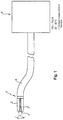
- FIG. 1 shows the conceptual arrangement of a surgical implant-cutting instrument operated with direct current and of the bipolar type, according to a preferred exemplary embodiment of the present invention
- FIG. 2 shows the conceptual construction of two rigid instrument branches at a distal instrument head
- FIGS. 3 a and 3 b show the conceptual construction of two elastic or elastically supported instrument branches at the distal instrument head in operating positions extended from and retracted into an insertion tool
- FIGS. 4 a and 4 b show the conceptual construction of two simply supported instrument branches at the distal instrument head, with widened and narrowed cutting gap
- FIG. 5 shows the conceptual construction of two instrument branches at the distal instrument head in contact engagement (short circuit engagement) with an electrically conductive implant
- FIG. 6 shows the gripping or contact engagement principle between the cutting tool according to the invention and the electrically conductive implant
- FIG. 7 shows a comparison chart between the resistance-adjusted specific melting energy and the respective current density along an instrument-implant-current path
- FIG. 8 shows a resistance circuit diagram of the instrument-implant-current path for a test sequence of an electric/electronic contact quality detection device of the instrument control.
- FIG. 9 shows a resistance circuit diagram of the instrument-implant-current path for an application of power current (cutting sequence) of the instrument control.
- FIGS. 10 a to 10 e show a preferred exemplary embodiment for the construction of the instrument tip and/or of the instrument branches/electrodes
- FIG. 11 shows the basic principle of an electrical current path through a metallic implant on which two opposite-lying electrodes are punctiformly applied.
- FIG. 12 shows the electrical current path according to FIG. 11 according to the current densities to be expected in individual path sections.
- FIG. 13 shows the electrical current path according to FIG. 11 as well as the thermal effect on an implant in the transition region/contact region between implant and electrodes and
- FIG. 14 shows a table referring to the energy absorption characteristics of different electrically conductive materials.
- the surgical implant-cutting tool of the bipolar type shown schematically in FIG. 1 has a distal instrument head or an instrument tip 1 with (at least) two instrument branches 2 which therebetween define a longitudinal gap 4 extending in the longitudinal direction of the instrument.
- the instrument head 1 is mounted at a distal end of a preferably bendably flexible (or alternatively rigid) instrument shank 6 having at least two poles and which in turn is attached to a controlled/guided or controllable/guidable DC current generator 8 .
- the DC current generator 8 delivers a direct current of preferably optionally between 100 A-150 A with a voltage of preferably optionally 20 V-40 V.
- the gap formed between the instrument branches 2 has essentially a V-shape that narrows in the proximal direction.
- the instrument shank 6 and also the instrument head 1 have an outer diameter (for example 6 mm max.) that permits the surgical instrument to be insertable into the (standardized) working channel of an endoscope, trocar or similar insertion tool, which is known per se.
- the instrument shank and instrument head may be configured and dimensioned such that it can be introduced in the manner of a catheter (without insertion tool) into a patient's hollow organ.
- FIG. 2 shows in enlarged view a variant for a branch construction according to the invention.
- the instrument branches 2 are connected to the instrument head 1 and in addition executed to be rigid. Electrically conductive electrodes 10 are arranged on the mutually facing longitudinal sides of each branch 2 , which electrodes 10 are connected via two electrical conductors (not shown) inside of the instrument shank 6 with the DC current generator 8 .
- the branches 2 may thereby themselves form the electrodes 10 , for which they must however be electrically insulatedly fixed to the instrument head 1 .
- the instrument branches 2 may however even be equipped/loaded with external electrodes 10 .
- the formation/arrangement of the electrodes 10 as well as of their connection to the DC current generator is the same for all the variants that are described in the following, so that it is not described repeatedly.
- the branches 2 and/or the electrodes 10 are made from a bendably flexible, preferably elastic material, or the electrodes 10 are spring-loaded against the respective instrument branches 2 such that they can be elastically pushed into the branches 2 under increasing gap width.
- an outer sleeve 12 is provided at least at the distal end region of the instrument, which is axially movable relative to the instrument.
- This sleeve 12 may be a separate component or the insertion tool itself.
- the instrument is shown in a position in which the instrument head 1 , or at least the instrument branches 2 , extend axially from the sleeve 12 and in addition spread apart radially (elastically), whereby the cutting gap 4 widens.
- the instrument head 1 or the instrument branches 2 is/are withdrawn into the sleeve 12 , or the sleeve is advanced, whereby the instrument branches 2 are compressed together against their own elasticity when the cutting gap 4 narrows.
- the sleeve 12 may be shaped at its distal end to form an inner ring or torus 14 which enters into/remains in sliding engagement with the instrument head 1 or the instrument branches 2 , with guiding quality.
- branches 2 per se are preferably rigidly formed, while also being pivotably supported (like scissors) at the instrument head 1 .
- an actuation device or setting device in the form of a pullrod/pushrod 16 is provided, which is hinged at the branches 2 to transform an axial movement of the rod 16 into a pivoting movement of the branches 2 . In this way the cutting gap between the branches 2 can be adjusted.
- FIG. 5 the branches 2 are shown in a maximum gap width position
- FIG. 6 shows the instrument with instrument branches 2 closed together by means of the setting device, to define a minimum gap width.
- FIG. 7 the functional principle of the DC powered implant-cutting instrument of bipolar type, according to the invention, is shown.
- the instrument branches 2 are basically spaced or spaceable such that the cutting gap 4 which forms longitudinally therebetween has a gap width which permits/ensures an introduction of an implant or implant section 18 (stent wire) into the gap 4 when coming into contact with the two mutually opposing longitudinal branches 2 /electrodes 10 .
- the instrument branches 2 are for this purpose banana-shaped/convexly rounded at least in the region of their distal (free) end sections, to form a convex longitudinal curve, at least in longitudinal sections, at the mutually facing branch sides.
- the cutting gap 4 tapers not (necessarily) linearly, but rather along a curve. It goes without saying that the electrodes 10 are suited to fit this curve path.
- the implant 18 slides deeper and deeper into the tapering cutting gap 4 , wherein the electrodes 10 preferably also dissect the melted implant material.
- the instrument branches 2 and/or at least the electrodes 10 comprise a sort of blade shape with a narrow (sharp) longitudinal edge on the mutually facing longitudinal sides of each branch 2 .
- a narrow (sharp) longitudinal edge on the mutually facing longitudinal sides of each branch 2 .
- the instrument branch 2 and the electrode 10 in the preferred exemplary embodiment are formed (materially) integrally, i.e. the instrument branch 2 forms at the same time the electrode 10 .
- the instrument branch 2 is made from a heat resistant material, preferably wolfram or a low-alloy steel.
- Each branch 2 is shaped at its proximal end section into a sort of hollow pin 2 a which is inserted in a corresponding receiving socket/receiving sleeve 1 a on sides of the instrument head 1 , in accordance with FIG. 10 e . Accordingly two receiving sleeves 1 a are provided for the two branches 2 , which according to FIG. 10 e are separated from each other by an insulating piece/distance piece 1 b of the instrument head 1 .
- each branch 2 is formed (ground/milled) into a blade shape having a partially circular-shaped back of the blade 2 b and a blade edge 2 c which is curved to be banana shaped in the longitudinal direction.
- the blade shape may be configured such that two (straight) longitudinal sections are provided standing obtusely with respect to each other, whereby the banana shape is approximated with the forming of a single kink. In this way a narrow (sharp) longitudinal edge/cutting edge 2 e occurs at the one longitudinal side of each branch 2 , which extends arcuately in the longitudinal branch direction (corresponding to the longitudinal direction of the instrument).
- each conductor bundle 6 a , 6 b can achieve a comparatively large conductor thickness despite a low maximum shank outer diameter in order to conduct a sufficient electric current with comparatively lower current density (without it heating up).
- the passage from each conductor bundle 6 a , 6 b is made preferably from copper on the associated branch 2 , preferably from wolfram/steel over the clamping sleeve 1 a and thereby without large losses.
- Each branch 2 thereby forms a cutting edge 2 e , which also simultaneously defines the contact line with the implant 18 and which thus generates a high contact resistance (and with it a high current density).
- the cutting edge 2 e serves preferably for the mechanical dissecting of the electrically melted implant material.
- the surgical instrument has a contact-quality-detection function, as will be described in the following with reference to FIGS. 6-9 .
- the contact grip between instrument and implant is functionally depicted in FIG. 6 .
- an electric current is guided via the copper conductors 6 a , 6 b in the instrument shank 6 to the instrument branches 2 and from there introduced via the point or line contact into the implant section between the branches.
- a high contact resistance is thereby achieved.
- the implant 18 is not clamped exactly between the contact edges 2 e of the instrument branches 2 or electrodes, but rather bears over a large area on the electrode of each branch 2 .
- the contact resistance between the electrode and the implant would be distinctly reduced (current density reduces) such that much more current would have to be conducted in the conductors 6 a , 6 b in order to achieve a melting of the implant material. This serves to avoid heating of the entire implant.
- FIG. 7 shows the course of the material properties in the current path of the surgical implant-cutting instrument.
- the term “resistance-adjusted specific melting energy” e is to be introduced, as is given in FIG. 14 for some selected materials.
- This measure describes how easily a specific volume (e.g. 1 mm 3 ) of a conducting material (e.g. a predefined metal) can be melted by a current flow. This measure is calculated according to the following formula:
- e c ⁇ V ⁇ ⁇ ⁇ ( T S - T 0 ) ⁇ 1 r having the following parameters: e resistance-adjusted specific melting energy c specific heat capacity V material volume ⁇ mass density T S melting temperature T O temperature before energy input r specific electrical resistance
- the resistance-adjusted specific melting energy e for each of these metals is approximately (given in 10 15 J m ⁇ 4 ⁇ ⁇ 1 ):
- Nickel-titanium 4.86
- nickel-titanium melts faster than unalloyed steel by the ratio 39 to 4.86 (approx. 8 ⁇ ), while nickel-titanium melts faster than copper by the corresponding ratio 210 to 4.86 (approx. 43 ⁇ ).
- This assumes the same current density in the material.
- it is made possible, through material choice on the basis of the resistance-adjusted specific melting energy, to dose an electrical direct current which flows through the conductor, the electrode and the stent material, such that it selectively melts the stent material while the electrodes and the conductor do not reach the melting temperature during the current impulse.
- the materials are selected such that the resistance-adjusted specific melting energy of the materials which are not to be melted (in particular conductor material and electrode material) is at least twice the resistance-adjusted specific melting energy of those materials that are to be melted (in particular the material of the implant to be cut).
- the invention to control the current density such that the current density in the target metal to be melted is higher than in the conducting lines and electrodes of the instrument.
- This is solved by the configuration, according to the invention, of the electrodes whereby a punctiform or linear contact surface is created between electrode and the metal to be cut, which leads to a high current density.
- the melting of the target material is additionally accelerated in comparison with the electrode material and conductor material.
- the contact quality between electrode and the metal to be melted is strongly dependent on each gripping situation.
- An optimal contact quality is promoted by the configuration, according to the invention, of the electrodes.
- it is useful to carry out an electrical check of the contact quality.
- the resistance path along the electrical path is marked out in FIG. 7 .
- the two contact locations represent resistance peaks, while the current is guided nearly without losses in the remaining path sections.
- the individual conductor sections of the electrical path form individually identifiable resistances from which only the contact resistances R K1,2 are initially of interest.
- the conducting path is thereby formed from the conductor bundles 6 a , 6 b in the instrument shank 6 , the branches 2 , the contact locations as well as the implant 18 .
- a small test current below the later cutting current is applied to the electrical path and a reference voltage is directly tapped at the distal end of the conductor bundles 6 a , 6 b .
- the conductor bundle resistance may be calculated from the difference between the applied voltage and the tapped voltage.
- the contact resistance R K1,2 can be determined in this way.
- the contact-quality-detection function has the ability to give a warning signal for an incorrect gripping position and/or to block the supply of a cutting current and/or to correct the amount of the cutting current to below the load limit of the conductor bundles 6 a , 6 b.
- the cutting current or power current itself may be used for test purposes, wherein in this case the cutting current may be applied for only a short time in order to keep the energy input into the implant smaller than the energy input that would be required to melt the implant material.
- a circuit (see FIG. 9 ) suited for the implementation of the functional principle according to FIG. 8 is actuated in order to disable the initially applied test current/power current sequence, and to replace it with a power current (cutting current) which, as is shown, is controllable at least dependently on the predetermined contact resistance R K1,2 .
- a power current cutting current
- factors such as the cutting temperature, the voltage level, the temperature in the conductor bundle, etc. can influence the setting procedure of the cutting current.
- an “emergency stop” function may be provided, which for example in the case of a contact break at the electrodes switches off the current supply in order to avoid arcing.
- the crystal lattice of a metal has a characterizing thermal energy which manifests itself in vibrations of the atoms of the lattice. Thermal energy is thereby a kinetic energy.
- the thermal energy as well as the electrical energy is usually given with the units of Watt Seconds (Ws) or Joules (J).
- the outflow of the thermal energy into the surroundings according to the above relationship has a strong dependence on the impulse duration ⁇ t. That is, the shorter the pulse, the less thermal energy flows away.
- the Temperature rise ⁇ T can be calculated as follows:
- ⁇ ⁇ ⁇ T 1 c ⁇ ⁇ ⁇ E el V - k ⁇ ⁇ ⁇ ⁇ ⁇ t ⁇ ⁇ ⁇ ⁇ T ⁇ ( t ) ⁇ ⁇ dt
- a reduction of the impulse duration according to point c) leads simultaneously to a reduction of the electric energy E el according to point a). However this may be compensated by an increase of the electrical power P. It is therefore appropriate to minimize the impulse duration ⁇ t (in order to minimize the heat dissipation during the energy input) and simultaneously to maximize the electrical power P (in order to deliver sufficient electrical energy E el despite lower impulse duration).
- the bipolar cutting instrument creates a local heating of a gripped piece of metal (with the aim of local melting), which heating is as strong as possible, while making a required input of electrical energy as small as possible.
- the gripped target metal should be melted while the instrument material should remain intact and the surrounding tissue should remain undamaged.
- the cutting process is influenced on the one hand by material constants, and on the other hand by the geometric proportions relating to the current path and which in particular determine the current density.
- the melting of an elemental volume by electric direct current according to FIG. 13 may be calculated as follows:
- the thermal energy E th that is necessary to melt an elemental volume according to FIG. 11 of a material is dependent on the start temperature T O of the melting temperature T S , the specific heat capacity c as well as the specific weight (mass density) ⁇ : E th ⁇ V ⁇ ( T S ⁇ T O )
- T O 38° C. (body temperature) and a standard volume of 1 mm 3 gives rise to values for the melting energy per mm 3 according to the following table ( FIG. 14 ).
- the readiness of a material to convert electrical energy into thermal energy is proportional to the ohmic resistance of the material.
- the specific melting energy is adjusted by the ohmic resistance (by multiplication with the reciprocal value of the resistance). This gives a measure on the basis of which a comparability of the materials with respect to their energy absorption characteristics and suitability for use in the current path is possible.
- unalloyed steel is suited very well as an electrode material for cutting nickel-titanium because this measure (i.e. the specific melting energy adjusted by the resistance factor) for unalloyed steel, being 39, is distinctly higher than for nickel-titanium, being 4.86 (last column in FIG. 14 ). In other words when the same current flows through both materials, nickel-titanium melts faster than unalloyed steel by the ratio 39 to 4.86.
- a surgical implant-cutting instrument of the bipolar type operated with direct current, is disclosed, with an instrument head which is located at the distal end of an instrument shank and which is provided for minimally invasive insertion of the instrument into a patient's body, wherein at least two mutually opposing instrument branches, preferably of the linear type, are arranged on the instrument head and between them define a cutting gap for receiving an electrically conductive implant or implant section between them.
- electrodes are formed on the mutually facing longitudinal sides of the branches or these are each equipped with at least one electrode, which electrodes are in turn shaped at their mutually facing longitudinal sides to form a cutting edge in order to effect a quasi linear or punctiform physical contact engagement with the electrically conductive implant or implant section for an electrical short circuit of the mutually opposing electrodes.
- the target metal of the implant is selectively melted, i.e. that the direct current melts the stent material but not the conductor/electrode material of the endoscopic surgical implant-cutting instrument.
- a suitable dose (setting) of current strength and impulse duration or impulse form is decisive for this purpose.
- contact quality is understood in this context to mean the conditions set for current density and current path length which arise when contacting of the implant material with the instrument. Influencing factors can for example be the concrete transformation of the gripped/contacted implant section. If the gripped/contacted implant section between the electrodes is thin and planar, there arises a small current density, but if it is narrow, there arises a high current density. The concrete contact situation can break down very differently in individual cases, such that different contact qualities result. In order to ensure a reliable cutting and at the same time to avoid an excessive energy input (which can lead to explosion effects or can damage the instrument), it is practical to adjust the current strength and impulse duration or impulse form.
- the contact quality may be performed via a resistance measurement.
- the current path can be described, according to FIG. 7 , via an equivalent circuit diagram with the following ohmic resistances arranged in series.
- the determination of contact quality occurs according to the principle of four-wire sensing. This is applied before the actual cutting process for the determination of appropriate cutting parameters (current strength, impulse duration and impulse form) as well as during the cutting process.
- the basic principle is shown in FIG. 8 .
- a small test current is introduced into the instrument before the cutting process such that the test current flows via the electrodes through the stent material to be cut.
- the voltage drop U T between the two electrodes and created by the test current may be measured via two conductors which are in electrical contact with the electrodes but through which the test current does not flow. This corresponds to a measurement of the resistances R E1 , R K1 , R M , R K2 and R E2 in the equivalent circuit diagram, according to the principle of four-wire sensing.
- the test current lies distinctly below the power current, preferably in the milliampere range (e.g. 20 mA).
- the determination of the contact quality it may also be determined whether an electrically conductive contact was made at all.
- a test impulse is sent before the cutting process (preferably when a stable electrical contact has been established), through the implant material to be cut, which leads to heating but does not lead to melting.
- a heating leads to an increase in the specific resistance of the material and therefore to an increase in the voltage U T between the electrodes and determined according to the principle of the four-wire method.
- a prognosis of the energy input required for melting may be computationally deduced based on the growth curves of the electrical resistance between the electrodes (which corresponds to the resistances R E1 , R K1 , R M , R K2 and R E2 in the equivalent circuit diagram). This may serve as basis for the setting of the cutting parameters.
- the cutting process may be monitored from the monitoring of the voltage U T between the electrodes with the aim of adjusting the cutting parameters as necessary, such that e.g. a foreseeably too-low parameter setting is corrected.
- the voltages U L1 and U L2 are determined. This takes place not only with the test current before the cutting process but also with the power current during the cutting process. Since the ohmic resistance of the conductor material changes with temperature, the ohmic resistance, and with it the temperature, can be ascertained by measurement of the voltage drop in the case of known current. This is appropriate in particular in order to recognize and avoid overheating of the instrument shank, through suitable setting of the cutting parameters or cancellation of the cutting process.
- the temperature coefficient of various conductive materials is shown in FIG. 14 .
- test current is preferably many times smaller than the power current, it is appropriate to be able to optionally electronically amplify the measurement of the voltages U T , U L1 and U L2 .
- a simplified suitable circuit is shown in FIG. 9 .
Landscapes
- Health & Medical Sciences (AREA)
- Surgery (AREA)
- Engineering & Computer Science (AREA)
- Life Sciences & Earth Sciences (AREA)
- Biomedical Technology (AREA)
- Otolaryngology (AREA)
- Nuclear Medicine, Radiotherapy & Molecular Imaging (AREA)
- Plasma & Fusion (AREA)
- Physics & Mathematics (AREA)
- Heart & Thoracic Surgery (AREA)
- Medical Informatics (AREA)
- Molecular Biology (AREA)
- Animal Behavior & Ethology (AREA)
- General Health & Medical Sciences (AREA)
- Public Health (AREA)
- Veterinary Medicine (AREA)
- Surgical Instruments (AREA)
Applications Claiming Priority (4)
| Application Number | Priority Date | Filing Date | Title |
|---|---|---|---|
| DE102013102418.1 | 2013-03-11 | ||
| DE102013102418.1A DE102013102418A1 (de) | 2013-03-11 | 2013-03-11 | Chirurgischer Gleichstromschneider |
| DE102013102418 | 2013-03-11 | ||
| PCT/EP2014/054740 WO2014140039A1 (de) | 2013-03-11 | 2014-03-11 | Chirurgischer gleichstromschneider |
Publications (2)
| Publication Number | Publication Date |
|---|---|
| US20160022356A1 US20160022356A1 (en) | 2016-01-28 |
| US10881454B2 true US10881454B2 (en) | 2021-01-05 |
Family
ID=50241439
Family Applications (1)
| Application Number | Title | Priority Date | Filing Date |
|---|---|---|---|
| US14/774,694 Active 2036-01-06 US10881454B2 (en) | 2013-03-11 | 2014-03-11 | Surgical cutter operated with direct current |
Country Status (6)
Cited By (1)
| Publication number | Priority date | Publication date | Assignee | Title |
|---|---|---|---|---|
| US11246647B2 (en) | 2016-05-11 | 2022-02-15 | Ovesco Endoscopy Ag | Medical DC current generator and bipolar medical implant fragmentation device equipped therewith |
Families Citing this family (6)
| Publication number | Priority date | Publication date | Assignee | Title |
|---|---|---|---|---|
| EP3592274A4 (en) * | 2017-03-08 | 2021-04-07 | Memic Innovative Surgery Ltd. | ELECTROSURGERY DEVICE |
| US11350977B2 (en) | 2017-03-08 | 2022-06-07 | Memic Innovative Surgery Ltd. | Modular electrosurgical device |
| DE202018101753U1 (de) | 2018-03-28 | 2018-05-08 | Tuebingen Scientific Medical Gmbh | Elektroden-Applikationsinstrument |
| USD888950S1 (en) * | 2018-10-10 | 2020-06-30 | Bolder Surgical, Llc | Yoke assembly for a surgical instrument |
| CN112168343B (zh) * | 2020-10-09 | 2023-05-16 | 杭州埃杜医疗科技有限公司 | 一次性射频等离子手术电极 |
| WO2022094087A1 (en) * | 2020-10-28 | 2022-05-05 | United States Endoscopy Group, Inc. | Cap for endoscope |
Citations (12)
| Publication number | Priority date | Publication date | Assignee | Title |
|---|---|---|---|---|
| US3354478A (en) | 1965-10-22 | 1967-11-28 | Ingersoll Rand Co | Wire cutting and connecting tool |
| US3431384A (en) | 1965-09-24 | 1969-03-04 | Sperry Rand Corp | Means for cutting wire by wire-melting electrical pulses |
| US20010037109A1 (en) * | 1998-01-23 | 2001-11-01 | Olympus Optical Co., Ltd. | High-frequency treatment tool |
| WO2007054321A2 (de) | 2005-11-10 | 2007-05-18 | Farin Guenter | Instrument und verfahren zur endoskopisch kontrollierten kürzung und/oder fragmentierung von in hohlorganen befindlichen stents |
| US20080015575A1 (en) * | 2006-07-14 | 2008-01-17 | Sherwood Services Ag | Vessel sealing instrument with pre-heated electrodes |
| WO2008040485A2 (de) | 2006-10-05 | 2008-04-10 | Erbe Elektromedizin Gmbh | Medizinisches instrument |
| WO2008090003A1 (de) | 2007-01-25 | 2008-07-31 | Erbe Elektromedizin Gmbh | Bipolares instrument und verfahren zur endoskopisch kontrollierten kürzung und/oder fragmentierung von im gastrointestinaltrakt, im tracheobronchialsystem oder in anderen hohlorganen befindlichen stents |
| US20080208193A1 (en) * | 2005-08-18 | 2008-08-28 | Ken Yamatani | Bipolar cutter |
| EP2392282A1 (en) | 2010-06-02 | 2011-12-07 | Tyco Healthcare Group, LP | Apparatus for performing an electrosurgical procedure |
| US20120265196A1 (en) | 2009-10-09 | 2012-10-18 | Ethicon Endo-Surgery, Inc. | Surgical generator for ultrasonic and electrosurgical devices |
| US20130030428A1 (en) | 2010-09-24 | 2013-01-31 | Ethicon Endo-Surgery Inc. | Surgical instrument with multi-phase trigger bias |
| US20140005667A1 (en) * | 2012-06-29 | 2014-01-02 | Ethicon Endo-Surgery, Inc. | Closed feedback control for electrosurgical device |
-
2013
- 2013-03-11 DE DE102013102418.1A patent/DE102013102418A1/de not_active Withdrawn
-
2014
- 2014-03-11 US US14/774,694 patent/US10881454B2/en active Active
- 2014-03-11 JP JP2015562097A patent/JP6194026B2/ja active Active
- 2014-03-11 ES ES14709301.7T patent/ES2628101T3/es active Active
- 2014-03-11 EP EP14709301.7A patent/EP2967712B1/de active Active
- 2014-03-11 WO PCT/EP2014/054740 patent/WO2014140039A1/de active Application Filing
Patent Citations (17)
| Publication number | Priority date | Publication date | Assignee | Title |
|---|---|---|---|---|
| US3431384A (en) | 1965-09-24 | 1969-03-04 | Sperry Rand Corp | Means for cutting wire by wire-melting electrical pulses |
| US3354478A (en) | 1965-10-22 | 1967-11-28 | Ingersoll Rand Co | Wire cutting and connecting tool |
| US20010037109A1 (en) * | 1998-01-23 | 2001-11-01 | Olympus Optical Co., Ltd. | High-frequency treatment tool |
| US20080208193A1 (en) * | 2005-08-18 | 2008-08-28 | Ken Yamatani | Bipolar cutter |
| WO2007054321A2 (de) | 2005-11-10 | 2007-05-18 | Farin Guenter | Instrument und verfahren zur endoskopisch kontrollierten kürzung und/oder fragmentierung von in hohlorganen befindlichen stents |
| US20090204064A1 (en) | 2005-11-10 | 2009-08-13 | Farin Guenter | Instrument and method for the endoscopically controlled shortening and/or fragmentation of stents located in hollow organs |
| JP2009514632A (ja) | 2005-11-10 | 2009-04-09 | ギュンテル・ファリン | 中腔臓器内に留置されたステントを内視鏡下制御により短縮化及び/又は断片化する器械及び方法 |
| US20080015575A1 (en) * | 2006-07-14 | 2008-01-17 | Sherwood Services Ag | Vessel sealing instrument with pre-heated electrodes |
| WO2008040485A2 (de) | 2006-10-05 | 2008-04-10 | Erbe Elektromedizin Gmbh | Medizinisches instrument |
| DE102007003838A1 (de) | 2007-01-25 | 2008-08-07 | Erbe Elektromedizin Gmbh | Bipolares Instrument und Verfahren zur endoskopisch kontrollierten Kürzung und/oder Fragmentierung von im Gastrointestinaltrakt, im Tracheobronchialsystem oder in anderen Hohlorganen befindlichen Stents |
| WO2008090003A1 (de) | 2007-01-25 | 2008-07-31 | Erbe Elektromedizin Gmbh | Bipolares instrument und verfahren zur endoskopisch kontrollierten kürzung und/oder fragmentierung von im gastrointestinaltrakt, im tracheobronchialsystem oder in anderen hohlorganen befindlichen stents |
| US20100087834A1 (en) * | 2007-01-25 | 2010-04-08 | Florian Eisele | Bipolar instrument and method for endoscopic controlled shortening and/or fragmentation of stents arranged in gastrointestinal tract in the tracheobronchial system or in other hollow organs |
| JP2010516361A (ja) | 2007-01-25 | 2010-05-20 | エルベ エレクトロメディツィン ゲーエムベーハー | ステントを内視鏡的制御によって短小化し且つ/又は分断するバイポーラ装置 |
| US20120265196A1 (en) | 2009-10-09 | 2012-10-18 | Ethicon Endo-Surgery, Inc. | Surgical generator for ultrasonic and electrosurgical devices |
| EP2392282A1 (en) | 2010-06-02 | 2011-12-07 | Tyco Healthcare Group, LP | Apparatus for performing an electrosurgical procedure |
| US20130030428A1 (en) | 2010-09-24 | 2013-01-31 | Ethicon Endo-Surgery Inc. | Surgical instrument with multi-phase trigger bias |
| US20140005667A1 (en) * | 2012-06-29 | 2014-01-02 | Ethicon Endo-Surgery, Inc. | Closed feedback control for electrosurgical device |
Non-Patent Citations (1)
| Title |
|---|
| Japanese Patent Office, Notification of Reasons for Rejection, dated Apr. 4, 2017, in application JP 2015-562097. |
Cited By (1)
| Publication number | Priority date | Publication date | Assignee | Title |
|---|---|---|---|---|
| US11246647B2 (en) | 2016-05-11 | 2022-02-15 | Ovesco Endoscopy Ag | Medical DC current generator and bipolar medical implant fragmentation device equipped therewith |
Also Published As
| Publication number | Publication date |
|---|---|
| DE102013102418A1 (de) | 2014-09-11 |
| JP6194026B2 (ja) | 2017-09-06 |
| EP2967712A1 (de) | 2016-01-20 |
| JP2016509908A (ja) | 2016-04-04 |
| EP2967712B1 (de) | 2017-03-08 |
| ES2628101T3 (es) | 2017-08-01 |
| US20160022356A1 (en) | 2016-01-28 |
| WO2014140039A1 (de) | 2014-09-18 |
Similar Documents
| Publication | Publication Date | Title |
|---|---|---|
| US10881454B2 (en) | Surgical cutter operated with direct current | |
| EP0696182B1 (en) | Impedance feedback electrosurgical system | |
| US5713896A (en) | Impedance feedback electrosurgical system | |
| KR102628063B1 (ko) | 대용적 조직 감소 및 제거 시스템 및 방법 | |
| ES2436418T3 (es) | Instrumento quirúrgico | |
| CN108882958B (zh) | 用于眼内手术的显微外科精密抓持和透热疗法夹钳及透热疗法切割装置 | |
| EP3072469B1 (en) | Vessel ablation system with adjustable ablation terminal | |
| EP2540242B1 (en) | An electrosurgical instrument and apparatus for use with the instrument | |
| US20100087834A1 (en) | Bipolar instrument and method for endoscopic controlled shortening and/or fragmentation of stents arranged in gastrointestinal tract in the tracheobronchial system or in other hollow organs | |
| US10682172B2 (en) | Electrochemical protection of conducting circuit in the body of a patient | |
| US20120046657A1 (en) | Stent Graft Fenestration | |
| RU2771423C2 (ru) | Хирургические узел, система и электродный узел | |
| US11246647B2 (en) | Medical DC current generator and bipolar medical implant fragmentation device equipped therewith | |
| ES2688041T3 (es) | Dispositivo bipolar para la resección quirúrgica de tejidos | |
| RU2299702C2 (ru) | Электрохирургический биполярный пинцет | |
| US20220151653A1 (en) | Cap for endoscope | |
| WO2018136039A1 (en) | Current inrush regulator | |
| HK40017659A (en) | Large volume tissue reduction and removal system and method | |
| FR2908285A1 (fr) | Dispositif de rechauffement autonome et de mise en place de pieces implantables realisees en metal a memoire de forme |
Legal Events
| Date | Code | Title | Description |
|---|---|---|---|
| AS | Assignment |
Owner name: OVESCO ENDOSCOPY AG, GERMANY Free format text: ASSIGNMENT OF ASSIGNORS INTEREST;ASSIGNORS:SCHOSTEK, SEBASTIAN;HO, CHI-NGHIA;MELBERT, MICHAEL;AND OTHERS;SIGNING DATES FROM 20150820 TO 20150908;REEL/FRAME:036940/0830 |
|
| FEPP | Fee payment procedure |
Free format text: ENTITY STATUS SET TO SMALL (ORIGINAL EVENT CODE: SMAL); ENTITY STATUS OF PATENT OWNER: SMALL ENTITY |
|
| STPP | Information on status: patent application and granting procedure in general |
Free format text: FINAL REJECTION MAILED |
|
| STCB | Information on status: application discontinuation |
Free format text: ABANDONED -- FAILURE TO RESPOND TO AN OFFICE ACTION |
|
| STCC | Information on status: application revival |
Free format text: WITHDRAWN ABANDONMENT, AWAITING EXAMINER ACTION |
|
| STPP | Information on status: patent application and granting procedure in general |
Free format text: NOTICE OF ALLOWANCE MAILED -- APPLICATION RECEIVED IN OFFICE OF PUBLICATIONS |
|
| STCF | Information on status: patent grant |
Free format text: PATENTED CASE |