EP2966349A1 - Austragungsvorrichtung für kleinstückiges schüttgut - Google Patents
Austragungsvorrichtung für kleinstückiges schüttgut Download PDFInfo
- Publication number
- EP2966349A1 EP2966349A1 EP15174822.5A EP15174822A EP2966349A1 EP 2966349 A1 EP2966349 A1 EP 2966349A1 EP 15174822 A EP15174822 A EP 15174822A EP 2966349 A1 EP2966349 A1 EP 2966349A1
- Authority
- EP
- European Patent Office
- Prior art keywords
- bulk material
- conveyor
- channel
- chain
- conveyor chain
- Prior art date
- Legal status (The legal status is an assumption and is not a legal conclusion. Google has not performed a legal analysis and makes no representation as to the accuracy of the status listed.)
- Granted
Links
Images

Classifications
-
- F—MECHANICAL ENGINEERING; LIGHTING; HEATING; WEAPONS; BLASTING
- F23—COMBUSTION APPARATUS; COMBUSTION PROCESSES
- F23K—FEEDING FUEL TO COMBUSTION APPARATUS
- F23K3/00—Feeding or distributing of lump or pulverulent fuel to combustion apparatus
-
- F—MECHANICAL ENGINEERING; LIGHTING; HEATING; WEAPONS; BLASTING
- F23—COMBUSTION APPARATUS; COMBUSTION PROCESSES
- F23B—METHODS OR APPARATUS FOR COMBUSTION USING ONLY SOLID FUEL
- F23B50/00—Combustion apparatus in which the fuel is fed into or through the combustion zone by gravity, e.g. from a fuel storage situated above the combustion zone
- F23B50/12—Combustion apparatus in which the fuel is fed into or through the combustion zone by gravity, e.g. from a fuel storage situated above the combustion zone the fuel being fed to the combustion zone by free fall or by sliding along inclined surfaces, e.g. from a conveyor terminating above the fuel bed
-
- F—MECHANICAL ENGINEERING; LIGHTING; HEATING; WEAPONS; BLASTING
- F23—COMBUSTION APPARATUS; COMBUSTION PROCESSES
- F23G—CREMATION FURNACES; CONSUMING WASTE PRODUCTS BY COMBUSTION
- F23G2205/00—Waste feed arrangements
- F23G2205/12—Waste feed arrangements using conveyors
- F23G2205/124—Chain conveyor
-
- F—MECHANICAL ENGINEERING; LIGHTING; HEATING; WEAPONS; BLASTING
- F23—COMBUSTION APPARATUS; COMBUSTION PROCESSES
- F23K—FEEDING FUEL TO COMBUSTION APPARATUS
- F23K2200/00—Pretreatment and supply of solid fuel
-
- F—MECHANICAL ENGINEERING; LIGHTING; HEATING; WEAPONS; BLASTING
- F23—COMBUSTION APPARATUS; COMBUSTION PROCESSES
- F23K—FEEDING FUEL TO COMBUSTION APPARATUS
- F23K2203/00—Feeding arrangements
- F23K2203/20—Feeding/conveying devices
Definitions
- the present invention relates to a discharge device for small-sized bulk material according to the preamble of claim 1.
- a discharge device has a bulk material storage for the small-sized bulk material.
- the small piece of bulk material usually consists of wood chips, wood shavings, straw chaff or the like. From the bulk material store, the small piece of bulk material is conveyed out by a conveyor and conveyed to a combustion device or a gasification system, where it is converted into heat.
- Such a discharge device is for example from the DE-A-34 10 546 known.
- This screw conveyor is helical. In the cavities of the coil, the bulk material is compressed and compressed. The forces and stresses exerted by the bulk material in the screw conveyor increase proportionally as the distance to the bulk goods store increases. This implies a long-term risk of breakage for the screw conveyor.
- the screw conveyor is only suitable for bridging comparatively short distances between the bulk material store and the firing device, because the auger would otherwise seize up.
- a discharge device with a screw conveyor between bulk material storage and combustion device also shows the DE 32 00 727 , There is a hydraulic drive with eccentrically acting on a shaft hydraulic cylinders proposed as a special feature.
- the helix on the screw conveyor produces a notch effect. If the screw conveyor is bent or deformed by compacting bulk material or mineral contaminants present in the bulk material, the Break screw conveyor long term. A broken screw conveyor leads to short-term failure of the entire system, because the screw conveyor not only promotes the bulk material and thus the fuel from the bulk material storage, but also drives the milling device, which passes through the bulk material in the bulk material storage and further chaffs.
- a straw-incinerator feeder is known.
- Part of this feeding device is a milling device, which is fed with straw bales via a chain conveyor.
- the straw bales are separated by means of the milling device and collected in a collecting container.
- the scattered straw is fed as fuel from a press roll via a press channel into the incinerator.
- the structure of this feeder is considered to be technically very complicated and therefore less practical.
- an incinerator system with incontinence system waste is known as fuel.
- the incontinence system fuel is initially stored in a bunker and conveyed via a bulk soil and a subsequent conveyor belt in a separation unit.
- the separated waste is comminuted in a further comminution unit and introduced into a feed unit.
- the feed unit is charged with additional fuel, for example wood chips or the like.
- the resulting fuel mixture is fed to the combustion unit by means of a chain conveyor.
- the structure of this system, especially in the area between storage bunker and charging unit is also considered very complicated and therefore little practical.
- the work process that can be realized with the system consists of a large number of individual steps.
- this incinerator is particularly suitable for the combustion of special system waste in connection with wood chips, so for combustion of a fuel mixture of different fuels.
- the present invention relates to a discharge device for generally homogeneous bulk material.
- the invention is based on the object of improving a discharge device with regard to its service properties. This object is achieved by the feature combination of claim 1 in an inventive manner.
- the dependent claims teach advantageous and self-inventive developments of this invention.
- the invention is based on the basic idea of substituting the known auger by a conveyor chain.
- the conveyor chain has the advantage that it is flexible in itself and thus can dodge in the presence of compaction or mineral contaminants, so to speak, without being damaged themselves.
- the bulk material is neither compressed nor changed in its structure. In this way, the forces exerted by the chain on the bulk material remain the same over the entire transport path, so that with the conveyor chain larger distances between bulk material storage and combustion device can be bridged.
- the conveyor chain according to the invention also serves as a drive means for the milling device. In addition to its conveying function, it thus fulfills a drive function.
- This dual function also causes savings on components, which simplifies the discharge device structurally. This simplification in turn entails a reduced susceptibility to failure of the delivery device.
- Such block chains are known, for example, as bicycle chains or motorcycle chains and as drive chains for the crank drive of an engine.
- Such block chains each have two opposing tabs. These tabs are each broken at the end by a bearing eye. In each case two tabs of adjacent chain links are penetrated by a common bolt and the bolt is fixed in the bearing lugs of the tabs. On the bolt a sliding roller is pushed in each case, which is also fixed between the tabs.
- the chain links alternate on the outer sides each overlapping inner plates and outer plates from.
- the outer plates each carry a blade-like transverse extension. In this way, the block chain can be performed with the rollers within the chain links of drive and driven gears and promote the bulk material through one of the conveyor chain associated conveyor channel or conveyor trough from the bulk material store to the burner with the transverse processes.
- This conveyor channel is open in the region of the bulk material store which is overlapped by the milling arms of the milling device and closed at the top thereafter. In this way, the bulk material from the bulk material store can fall into the conveyor channel and be transported from the conveyor chain to the burner. In the conveyor channel thus runs the load of the conveyor chain.
- the conveyor chain slides over the bottom of the conveyor channel.
- the transverse processes engage behind the bulk material particularly effectively from below and pull it in the conveying direction with the movement of the conveyor chain.
- the transverse processes thus grab like small blades into the bulk material and promote it in the direction of the burner. It is considered advantageous to arrange the blade-like transverse extensions obliquely to the channel bottom of the conveyor channel.
- the helix angle between the channel bottom and the back of the transverse processes is between 45 ° and 90 °.
- the conveyor chain is driven by a motor gear and has on the output side a pinion, which is kinematically coupled to a transmission.
- This gearbox serves to drive the milling device in the bulk material store.
- Fig. 1 shows first the pressure plate 1 and the cutting arms 2 with their arms 3 arranged in the bulk material store not shown Fräs worn.
- the milling device corresponds in its structure and in its function of the EP-B-2 385 006 known milling arrangement.
- the pressure plate 1 rests on a drive shaft 4.
- the drive shaft 4 is driven by the arranged below the drive shaft 4 gear 5 and acted upon by torque.
- the milling arms 2 with their arms 3 rotate in the direction of rotation 6 in the bulk material store, not shown, and thus promote the small-sized bulk material, namely woodchips in the designed as a U-shaped conveyor trough conveyor channel 7.
- the trough-like conveyor channel 7 is in Auskrag Scheme the cutter arms 2 and the boom 3 above open.
- the conveyor chain 9 is driven by a drive motor 11.
- the drive motor 11 sets a drive gear 12 in rotation.
- the drive gear 12 in turn engages with its teeth in the chain links 13 of the conveyor chain 9 a.
- the conveyor chain 9 is initially configured in terms of their chain construction as a block chain.
- Such block chains are known and familiar, for example, as bicycle chains from the prior art.
- the chain links 13 consist of each other at the end overlapping and in the discharge direction 10 alternating outer flaps 14 and inner plates 15.
- the outer plates 14 and the inner plates 15 have at their two end sides in each case bearing eyes 16.
- the bearing lugs 16 of the outer flap 14 and the adjacent inner flap 15 are superimposed so that they are aligned.
- the bearing eyes 16 are penetrated by a bearing pin 17.
- the bearing bolts 17 each carry a bearing roller 18 in the area between the inner plates 15.
- the transverse extensions 19 extend in the Abinnecardi 10 perpendicular transverse direction 20.
- the transverse extensions 19 are formed like a blade and are obliquely relative to the Channel bottom 8 of the conveyor channel 7 arranged on the outer plates 14 of the conveyor chain 9, that when the channel bottom 8 forms the zero line, the angle 21 to the channel bottom between 45 ° and 90 °.
- the driven by the drive motor 11 via the drive gear 12 conveyor chain 9 promotes with their transverse processes 19 in the trough-shaped conveyor channel 7 small-sized bulk material in Abddycardi 10 from the bulk material store out.
- the area of the conveying channel 7 which is not spanned by the cutter arms 2 and their jibs 3 in the discharge direction 10 is thereby closed by means of a cover plate 22.
- Fig. 4 thus shows the spanned by the cutter arms 2 and their arms 3 open area of the conveying channel 7, while Fig. 5 the closed area of the conveyor channel 7 shows. Undercut the transverse processes 19 and engage behind the small-sized bulk material so efficiently that the entire amount of bulk material is conveyed in Abddycardi 10 through the conveyor channel 7 from the bulk material store out to the combustor.
- the conveyor chain 9 In the region of the drive gear 10, the conveyor chain 9 is deflected by 180 ° and returned by a running below the conveyor channel 7 return channel 23 against the Ab lakecardi 10. The further 180 ° deflection again into the conveying channel 7 takes place at the drive gear 12 in Abinnecardi 10 facing away from gear 24.
- the conveyor chain 9 At the gear 24, the conveyor chain 9 is deflected on the one hand in the conveying channel 7 and on the other hand, the drive torque for the drive shaft 4 of the pressure plate 1 and the cutting arms 2 driving gear 5 introduced. In the conveying channel 7 thus runs the Lasttrum the conveyor chain 9 and the return passage 23, the empty strand of the chain.
Landscapes
- Engineering & Computer Science (AREA)
- Chemical & Material Sciences (AREA)
- Combustion & Propulsion (AREA)
- Mechanical Engineering (AREA)
- General Engineering & Computer Science (AREA)
- Physics & Mathematics (AREA)
- Thermal Sciences (AREA)
- Screw Conveyors (AREA)
- Filling Or Emptying Of Bunkers, Hoppers, And Tanks (AREA)
Abstract
Description
- Die vorliegende Erfindung betrifft eine Austragungsvorrichtung für kleinstückiges Schüttgut gemäß dem Oberbegriff des Anspruchs 1. Eine derartige Austragungsvorrichtung weist einen Schüttgutspeicher für das kleinstückige Schüttgut auf. Das kleinstückige Schüttgut besteht in der Regel aus Hackschnitzeln, Hobelspänen, Strohhäckseln oder dergleichen. Aus dem Schüttgutspeicher wird das kleinstückige Schüttgut von einem Förderer hinausgefördert und zu einer Brenneinrichtung bzw. einem Vergasungssystem gefördert, um dort in Wärme umgewandelt zu werden.
- Eine derartige Austragungsvorrichtung ist beispielsweise aus der
DE-A-34 10 546 bekannt. Dort dient als Förderer zwischen Schüttgutspeicher und Brenneinrichtung bzw. Vergasungseinrichtung eine Förderschnecke. Diese Förderschnecke ist wendelförmig. In den Hohlräumen der Wendel wird das Schüttgut gestaucht und komprimiert. Die in der Förderschnecke vom Schüttgut ausgeübten Kräfte und Spannungen steigen mit wachsendem Abstand zum Schüttgutspeicher proportional an. Dies impliziert langfristig eine Bruchgefahr für die Förderschnecke. In Folge der Kompression des Schüttguts wird das Schüttgut in unerwünschter Weise verdichtet und ändert auch seine Gefügestruktur. Außerdem eignet sich die Förderschnecke nur zur Überbrückung vergleichsweise kurzer Distanzen zwischen Schüttgutspeicher und Brenneinrichtung, weil die Förderschnecke sich ansonsten festfressen würde. Eine Austragungsvorrichtung mit einer Förderschnecke zwischen Schüttgutspeicher und Brenneinrichtung zeigt auch dieDE 32 00 727 . Dort ist als Besonderheit ein Hydraulikantrieb mit exzentrisch an einer Welle angreifenden Hydraulikzylindern vorgeschlagen. - Schließlich erzeugt die Wendel an der Förderschnecke eine Kerbwirkung. Wird die Förderschnecke durch sich verdichtendes Schüttgut oder durch im Schüttgut befindliche mineralische Verunreinigungen durchgebogen bzw. verformt, kann die Förderschnecke langfristig brechen. Eine gebrochene Förderschnecke führt zum kurzfristigen Ausfall der gesamten Anlage, weil die Förderschnecke nicht nur das Schüttgut und damit den Brennstoff aus dem Schüttgutspeicher fördert, sondern auch die Fräseinrichtung, welche das Schüttgut im Schüttgutspeicher durchmengt und weiter kleinhäckselt, mit antreibt.
- Aus der
DE-A-30 31 395 ist eine Beschickungsvorrichtung für Stroh-Verbrennungsanlagen bekannt. Bestandteil dieser Beschickungsvorrichtung ist eine Fräseinrichtung, welche mit Strohballen über einen Kettenförderer beschickt wird. Die Strohballen werden mit Hilfe der Fräseinrichtung vereinzelt und in einem Auffangbehälter gesammelt. Vom Auffangbehälter wird das vereinzelte Stroh als Brennstoff von einer Presswalze angetrieben über einen Presskanal in die Verbrennungsanlage eingebracht. Der Aufbau dieser Beschickungsvorrichtung wird als technisch sehr aufwendig und damit wenig praktikabel angesehen. - Aus der
DE-A-10 2007 029 577 ist schließlich eine Verbrennungsanlage mit Inkontinenzsystemabfall als Brennstoff bekannt. Bei dieser Brennanlage wird der Inkontinenzsystembrennstoff zunächst in einem Bunker bevorratet und über einen Schüttboden und ein anschließendes Förderband in eine Vereinzelungseinheit gefördert. Der vereinzelte Abfall wird in einer weiteren Zerkleinerungseinheit zerkleinert und in eine Beschickungseinheit eingebracht. Aus einer separaten Zugabeeinheit wird die Beschickungseinheit mit zusätzlichen Brennstoff, beispielsweise Holzschnitzeln oder Ähnlichem beschickt. Das dadurch entstehende Brennstoffgemisch wird mit Hilfe eines Kettenförderers der Brenneinheit zugefördert. Der Aufbau dieser Anlage insbesondere im Bereich zwischen Vorratsbunker und Beschickungseinheit wird ebenfalls als sehr kompliziert und damit wenig praxisnah angesehen. Zudem setzt sich der mit der Anlage realisierbare Arbeitsprozess aus einer Vielzahl von Einzelschritten zusammen. Diese Vielzahl von Einzelschritten wird als nachteilig empfunden. Darüber hinaus eignet sich diese Verbrennungsanlage insbesondere für die Verbrennung spezieller Systemabfälle in Verbindung mit Hackschnitzeln, also zur Verbrennung einer Brennstoffmischung aus verschiedenen Brennstoffen. Die vorliegende Erfindung betrifft hingegen eine Austragungsvorrichtung für in der Regel homogenes Schüttgut. - Der Erfindung liegt hiervon ausgehend die Aufgabe zugrunde, eine Austragungsvorrichtung hinsichtlich ihrer Gebrauchseigenschaften zu verbessern. Diese Aufgabe ist durch die Merkmalskombination des Anspruchs 1 in erfinderischer Weise gelöst. Die rückbezogenen Ansprüche lehren vorteilhafte und für sich selbst erfinderische Weiterbildungen dieser Erfindung.
- Die Erfindung beruht auf der Grundüberlegung, die bekannte Förderschnecke durch eine Förderkette zu substituieren. Die Förderkette hat den Vorteil, dass sie in sich biegsam ist und somit beim Vorhandensein von Verdichtungen oder mineralischen Verunreinigungen gleichsam ausweichen kann, ohne selbst beschädigt zu werden. Außerdem wird beim Fördern mit einer Förderkette das Schüttgut weder komprimiert noch in seinem Gefüge verändert. Auf diese Weise bleiben die von der Kette auf das Schüttgut ausgeübten Kräfte über den gesamten Transportweg gleich, so dass mit der Förderkette größere Entfernungen zwischen Schüttgutspeicher und Brenneinrichtung überbrückt werden können.
- Ein weiterer Vorteil liegt in der Doppelfunktion der Förderkette. Die Förderkette dient erfindungsgemäß zugleich als Antriebsmittel für die Fräseinrichtung. Neben ihrer Förderfunktion erfüllt sie somit eine Antriebsfunktion. Diese Doppelfunktion bewirkt auch eine Ersparnis an Bauteilen, was die Austragungsvorrichtung konstruktiv vereinfacht. Diese Vereinfachung zieht wiederum eine reduzierte Störanfälligkeit der Austragungsvorrichtung nach sich.
- Als besonders vorteilhaft wird es angesehen, die Förderkette als Blockkette auszugestalten. Derartige Blockketten sind beispielweise als Fahrradketten oder Motorradketten sowie als Antriebsketten für den Kurbeltrieb eines Motors bekannt. Derartige Blockketten weisen jeweils zwei einander gegenüber liegende Laschen auf. Diese Laschen sind jeweils endseitig von einem Lagerauge durchbrochen. Jeweils zwei Laschen von einander benachbarten Kettengliedern sind von einem gemeinsamen Bolzen durchsetzt und der Bolzen ist in den Lageraugen der Laschen fixiert. Auf die Bolzen ist jeweils eine Gleitrolle aufgeschoben, welche ebenfalls zwischen den Laschen fixiert ist. Bei den Kettengliedern wechseln sich an den Außenseiten jeweils einander überlappende Innenlaschen und Außenlaschen ab. Erfindungsgemäß tragen vorzugsweise die Außenlaschen jeweils einen schaufelartigen Querfortsatz. Auf diese Weise kann die Blockkette mit den Rollen innerhalb der Kettenglieder von Antriebs- und Abtriebsverzahnungen geführt werden und mit den Querfortsätzen das Schüttgut durch einen der Förderkette zugeordneten Förderkanal oder Förderrinne vom Schüttgutspeicher zur Brenneinrichtung fördern.
- Als besonders vorteilhaft wird es angesehen, einen im Wesentlichen U-förmigen Förderkanal zwischen Stückgutspeicher und Brenneinrichtung vorzusehen. Dieser Förderkanal ist in dem von den Fräsarmen der Fräseinrichtung übergriffenen Bereich des Schüttgutspeichers oben offen und im Anschluss daran oben geschlossen. Auf diese Weise kann das Schüttgut vom Schüttgutspeicher in den Förderkanal hineinfallen und von der Förderkette zur Brenneinrichtung transportiert werden. Im Förderkanal läuft somit das Lastrum der Förderkette.
- Im Förderkanal gleitet die Förderkette gleichsam über den Boden des Förderkanals. Auf diese Weise hintergreifen die Querfortsätze das Schüttgut besonders effektiv von unten und ziehen es in Förderrichtung mit der Bewegung der Förderkette mit. Die Querfortsätze greifen also wie kleine Schaufeln in das Schüttgut hinein und fördern es in Richtung auf die Brenneinrichtung. Als vorteilhaft wird es angesehen, die schaufelartigen Querfortsätze schräg zum Kanalboden des Förderkanals anzuordnen. Der Schrägungswinkel zwischen Kanalboden und der Rückseite der Querfortsätze liegt zwischen 45°und 90°.
- Weiterhin vorteilhaft ist es, unterhalb des Förderkanals einen Rücklaufkanal für das Leertrum der Förderkette anzuordnen. Die Förderkette wird motorisch über ein Zahnrad angetrieben und weist abtriebsseitig ein Ritzel auf, welches kinematisch an ein Getriebe gekoppelt ist. Dieses Getriebe dient zum Antrieb der Fräseinrichtung im Schüttgutspeicher.
- Anhand des in den Zeichnungsfiguren dargestellten Ausführungsbeispiels ist die Erfindung mit näheren Einzelheiten erläutert. Es zeigen:
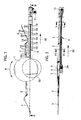
- Fig. 1
- eine Draufsicht auf die Fräseinrichtung und den Förderkanal mit der einliegenden Förderkette gemäß der Erfindung,
- Fig. 2
- den Schnitt II-II aus
Fig. 1 , - Fig. 3
- das Detail III aus
Fig. 1 , nämlich die Antriebswelle für die Fräseinrichtung und einen Teilbereich des Förderkanals mit einliegender Förderkette, - Fig. 4
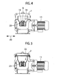
- den Schnitt IV-IV aus
Fig. 2 , - Fig. 5
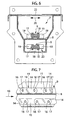
- den Schnitt V-V aus
Fig. 2 , - Fig. 6
- eine vergrößerte Darstellung des Förderkanals und des Rücklaufkanals mit jeweils einliegender Förderkette gemäß
Fig. 5 und - Fig. 7
- eine detaillierte Darstellung eines Teils der Förderkette im Förderkanal bzw. Rücklaufkanal gemäß dem in
Fig. 2 dargestellten Schnitt. -
Fig. 1 zeigt zunächst den Druckteller 1 und die Fräsarme 2 mit ihren Auslegern 3 der im nicht dargestellten Schüttgutspeicher angeordneten Fräseinrichtung. Die Fräseinrichtung entspricht in ihrem Aufbau und in ihrer Funktion der aus derEP-B-2 385 006 bekannten Fräsanordnung. Der Druckteller 1 ruht dabei auf einer Antriebswelle 4. Die Antriebswelle 4 wird von dem unterhalb der Antriebswelle 4 angeordneten Getriebe 5 angetrieben und mit Drehmoment beaufschlagt. - Die Fräsarme 2 mit ihren Auslegern 3 rotieren in Drehrichtung 6 im nicht dargestellten Schüttgutspeicher und fördern so das kleinstückige Schüttgut, nämlich Hackschnitzel in den als U-förmige Förderrinne ausgestalteten Förderkanal 7. Der rinnenartige Förderkanal 7 ist im Auskragbereich der Fräserarme 2 und deren Ausleger 3 oben offen.
- Mit Hilfe der am Kanalboden 8 entlanglaufenden Förderkette 9 wird das kleinstückige Schüttgut in Abförderrichtung 10 aus dem Schüttgutspeicher abgefördert in Richtung auf eine in den Zeichnungen nicht dargestellte Brenneinrichtung. Die Förderkette 9 ist dabei von einem Antriebsmotor 11 angetrieben. Der Antriebsmotor 11 versetzt ein Antriebszahnrad 12 in Rotation. Das Antriebszahnrad 12 greift seinerseits mit seinen Zähnen in die Kettenglieder 13 der Förderkette 9 ein.
- Die Förderkette 9 ist hinsichtlich ihres Kettenaufbaus zunächst als Blockkette ausgestaltet. Derartige Blockketten sind beispielsweise als Fahrradketten aus dem Stand der Technik bekannt und geläufig. Die Kettenglieder 13 bestehen dabei jeweils aus sich endseitig überlappenden und in Abförderrichtung 10 abwechselnden Außenlaschen 14 und Innenlaschen 15. Die Außenlaschen 14 und die Innenlaschen 15 weisen an ihren beiden Endseiten jeweils Lageraugen 16 auf. Die Lageraugen 16 der Außenlasche 14 und der benachbarten Innenlasche 15 werden so übereinander gelegt, dass sie miteinander fluchten. Im Montageendzustand sind die Lageraugen 16 von einem Lagerbolzen 17 durchsetzt. Die Lagerbolzen 17 tragen im Bereich zwischen den Innenlaschen 15 jeweils eine Lagerrolle 18.
- Die Außenlaschen 14 tragen auf ihren Außenflächen jeweils Querfortsätze 19. Während die Außenlaschen 14 sich in Abförderrichtung 10 erstrecken, erstrecken sich die Querfortsätze 19 in der zur Abförderrichtung 10 senkrecht verlaufenden Querrichtung 20. Die Querfortsätze 19 sind dabei schaufelartig ausgebildet und sind derartig schräg bezogen auf den Kanalboden 8 des Förderkanals 7 an den Außenlaschen 14 der Förderkette 9 angeordnet, dass wenn der Kanalboden 8 die Nulllinie bildet, der Winkel 21 zum Kanalboden zwischen 45° und 90° beträgt.
- Die vom Antriebsmotor 11 über das Antriebszahnrad 12 angetriebene Förderkette 9 fördert mit ihren Querfortsätzen 19 das im rinnenförmigen Förderkanal 7 einliegende kleinstückige Schüttgut in Abförderrichtung 10 aus dem Schüttgutspeicher heraus. Der von den Fräserarmen 2 und ihren Auslegern 3 in Abförderrichtung 10 nicht überspannte Bereich des Förderkanals 7 ist dabei mithilfe einer Abdeckplatte 22 verschlossen.
Fig. 4 zeigt somit den von den Fräserarmen 2 und deren Auslegern 3 überspannten offenen Bereich des Förderkanals 7, währendFig. 5 den verschlossenen Bereich des Förderkanals 7 zeigt. Die Querfortsätze 19 untergreifen und hintergreifen das kleinstückige Schüttgut derartig effizient, dass die gesamte Schüttgutmenge in Abförderrichtung 10 durch den Förderkanal 7 aus dem Schüttgutspeicher heraus zur Brenneinrichtung gefördert wird. - Im Bereich des Antriebszahnrads 10 wird die Förderkette 9 um 180 °umgelenkt und durch einen unterhalb des Förderkanals 7 verlaufenden Rücklaufkanal 23 gegen die Abförderrichtung 10 zurückgeleitet. Die weitere 180°-Umlenkung wieder in den Förderkanal 7 hinein erfolgt an dem dem Antriebszahnrad 12 in Abförderrichtung 10 abgewandten Getrieberitzel 24. Am Getrieberitzel 24 wird die Förderkette 9 einerseits in den Förderkanal 7 umgelenkt und andererseits wird das Antriebsdrehmoment für das die Antriebswelle 4 des Drucktellers 1 und der Fräsarme 2 antreibende Getriebe 5 eingebracht. Im Förderkanal 7 läuft somit das Lasttrum der Förderkette 9 und im Rücklaufkanal 23 das Leertrum der Kette.
- Infolge der Eigenelastizität der Förderkette 9 aufgrund der Verschwenkbarkeit der Kettenglieder 13 gegeneinander können zwischen die Antriebskette 9 und den Kanalboden 8 oder die Querfortsätze 19 und den Kanalboden 8 eindringende störende Verunreinigungen oder Schüttgut einfach durch ein Ausweichen der Förderkette ausgeglichen werden.
-
- 1
- Druckteller
- 2
- Fräserarm
- 3
- Ausleger
- 4
- Antriebswelle
- 5
- Getriebe
- 6
- Drehrichtung
- 7
- Förderkanal
- 8
- Kanalboden
- 9
- Förderkette
- 10
- Abförderrichtung
- 11
- Antriebsmotor
- 12
- Antriebszahnrad
- 13
- Kettenglied
- 14
- Außenlasche
- 15
- Innenlasche
- 16
- Lagerauge
- 17
- Lagerbolzen
- 18
- Lagerrolle
- 19
- Querfortsatz
- 20
- Querrichtung
- 21
- Winkel
- 22
- Abdeckplatte
- 23
- Rücklaufkanal
- 24
- Getrieberitzel
Claims (6)
- Austragungsvorrichtung für kleinstückiges Schüttgut mit einer in einem Schüttgutspeicher angeordneten Fräseinrichtung und mit einem eine Brenneinrichtung aus dem Schüttgutspeicher speisenden Förderer
gekennzeichnet durch
eine Förderkette (9) als Förderer und zugleich als Antriebsmittel für die Fräseinrichtung. - Vorrichtung nach Anspruch 1
gekennzeichnet durch
eine Blockkette als Förderkette (9) mit schaufelartigen Querfortsätzen (19) an den Laschen (14,15). - Vorrichtung nach Anspruch 1, oder 2
gekennzeichnet durch
einen im Wesentlichen U-förmigen Förderkanal (7) zwischen Schüttgutspeicher und Brenneinrichtung dessen U-Grund den Kanalboden (8) bildet, auf welchem die Förderkette (9) aufliegt. - Vorrichtung nach Anspruch 3
dadurch gekennzeichnet,
dass die die Querfortsätze (19) in einem Winkel (21) größer als 45° und kleiner als 90° schräg zum Kanalboden (8) verlaufen. - Vorrichtung nach einem der Ansprüche 1 - 4
gekennzeichnet durch
einen unterhalb des Förderkanals (7) angeordneten Rücklaufkanal (23) zur Aufnahme des Leertrums der Förderkette(9). - Vorrichtung nach einem der Ansprüche 1 - 5
gekennzeichnet durch
ein zwischen Förderkette (9) und Fräseinrichtung zwischengeschaltetes Getriebe (5).
Applications Claiming Priority (1)
| Application Number | Priority Date | Filing Date | Title |
|---|---|---|---|
| DE102014213340.8A DE102014213340B4 (de) | 2014-07-09 | 2014-07-09 | Austragungsvorrichtung für kleinstückiges Schüttgut |
Publications (2)
| Publication Number | Publication Date |
|---|---|
| EP2966349A1 true EP2966349A1 (de) | 2016-01-13 |
| EP2966349B1 EP2966349B1 (de) | 2016-10-12 |
Family
ID=52738205
Family Applications (1)
| Application Number | Title | Priority Date | Filing Date |
|---|---|---|---|
| EP15174822.5A Active EP2966349B1 (de) | 2014-07-09 | 2015-07-01 | Austragungsvorrichtung für kleinstückiges schüttgut |
Country Status (2)
| Country | Link |
|---|---|
| EP (1) | EP2966349B1 (de) |
| DE (1) | DE102014213340B4 (de) |
Cited By (2)
| Publication number | Priority date | Publication date | Assignee | Title |
|---|---|---|---|---|
| EP3964732A1 (de) | 2020-09-04 | 2022-03-09 | SL-Technik GmbH | 3-punkt drehmomentstütze |
| US11635231B2 (en) | 2019-09-03 | 2023-04-25 | Sl-Technik Gmbh | Rotating grate with a cleaning device for a biomass heating system |
Citations (7)
| Publication number | Priority date | Publication date | Assignee | Title |
|---|---|---|---|---|
| DE1801505A1 (de) * | 1968-10-05 | 1970-05-21 | Schwaebische Huettenwerke Gmbh | Fraesrotor fuer eine Silo-Austragvorrichtung |
| DE3031395A1 (de) | 1980-08-20 | 1982-04-01 | Wilhelm 4520 Melle Ackermann | Beschickungsvorrichtung fuer stroh-verbrennungsanlagen |
| DE3200727A1 (de) | 1982-01-13 | 1983-07-21 | Koch Transporttechnik GmbH, 6633 Wadgassen | "vorrichtung zum austragen des gutes aus einem silo" |
| DE3410546A1 (de) | 1984-03-22 | 1985-10-03 | Robert 8831 Meinheim Bloos | Vergasungssystem |
| DE102007029577A1 (de) | 2006-06-26 | 2008-01-17 | Stiftung Liebenau | Verbrennungsanlage |
| EP2385006B1 (de) | 2010-05-06 | 2012-11-28 | Helzomat-Gerätebau + Energiesysteme GmbH | Austragungsvorrichtung für kleinstückiges Schüttgut |
| EP2587150A2 (de) * | 2011-10-28 | 2013-05-01 | Hargassner GmbH | Vorrichtung zum Austragen von Schüttgut |
-
2014
- 2014-07-09 DE DE102014213340.8A patent/DE102014213340B4/de not_active Expired - Fee Related
-
2015
- 2015-07-01 EP EP15174822.5A patent/EP2966349B1/de active Active
Patent Citations (7)
| Publication number | Priority date | Publication date | Assignee | Title |
|---|---|---|---|---|
| DE1801505A1 (de) * | 1968-10-05 | 1970-05-21 | Schwaebische Huettenwerke Gmbh | Fraesrotor fuer eine Silo-Austragvorrichtung |
| DE3031395A1 (de) | 1980-08-20 | 1982-04-01 | Wilhelm 4520 Melle Ackermann | Beschickungsvorrichtung fuer stroh-verbrennungsanlagen |
| DE3200727A1 (de) | 1982-01-13 | 1983-07-21 | Koch Transporttechnik GmbH, 6633 Wadgassen | "vorrichtung zum austragen des gutes aus einem silo" |
| DE3410546A1 (de) | 1984-03-22 | 1985-10-03 | Robert 8831 Meinheim Bloos | Vergasungssystem |
| DE102007029577A1 (de) | 2006-06-26 | 2008-01-17 | Stiftung Liebenau | Verbrennungsanlage |
| EP2385006B1 (de) | 2010-05-06 | 2012-11-28 | Helzomat-Gerätebau + Energiesysteme GmbH | Austragungsvorrichtung für kleinstückiges Schüttgut |
| EP2587150A2 (de) * | 2011-10-28 | 2013-05-01 | Hargassner GmbH | Vorrichtung zum Austragen von Schüttgut |
Cited By (4)
| Publication number | Priority date | Publication date | Assignee | Title |
|---|---|---|---|---|
| US11635231B2 (en) | 2019-09-03 | 2023-04-25 | Sl-Technik Gmbh | Rotating grate with a cleaning device for a biomass heating system |
| US11708999B2 (en) | 2019-09-03 | 2023-07-25 | Sl-Technik Gmbh | Biomass heating system with optimized flue gas treatment |
| EP3964732A1 (de) | 2020-09-04 | 2022-03-09 | SL-Technik GmbH | 3-punkt drehmomentstütze |
| WO2022048769A1 (de) | 2020-09-04 | 2022-03-10 | Sl-Technik Gmbh | 3-punkt drehmomentstütze |
Also Published As
| Publication number | Publication date |
|---|---|
| EP2966349B1 (de) | 2016-10-12 |
| DE102014213340A1 (de) | 2015-04-16 |
| DE102014213340B4 (de) | 2017-10-19 |
Similar Documents
| Publication | Publication Date | Title |
|---|---|---|
| EP0327104B1 (de) | Backenbrecher | |
| DE3905535C1 (de) | ||
| DE102012014085A1 (de) | Pflückeinheit, Erntevorsatz und Erntemaschine für Mais oder dergleichen | |
| EP2965612A1 (de) | Schrägfördererzusammenbau für einen mähdrescher | |
| DE102019213022A1 (de) | Fördersystem | |
| DE3838979A1 (de) | Verfahren zum ernten von fruchtstaenden | |
| EP3386293B1 (de) | Geflügelbandanlage | |
| EP2966349B1 (de) | Austragungsvorrichtung für kleinstückiges schüttgut | |
| EP2992247B1 (de) | Kettenantrieb für gliederketten von bergbauförderern oder bergbaugewinnungsmaschinen | |
| DE102014107921A1 (de) | Antriebssystem für eine selbstfahrende Erntemaschine | |
| DE102008033917A1 (de) | Verbindungsanordnung, zwischen einer Einzugswalze und einem Getriebe eines Feldhäckslers | |
| DE69504603T2 (de) | Verfahren um Strohballen zu Zerlegen und Strohofen der dieses Verfahren benutzt | |
| EP2995192B1 (de) | Quaderballenpresse | |
| DE1213785B (de) | Beladevorrichtung, vorzugsweise fuer transportable Sammelbehaelter | |
| DD205597A5 (de) | Zufuehrvorrichtung fuer haeckselmaschinen | |
| DE102006030954B4 (de) | Antriebssystem einer landwirtschaftlichen Arbeitsmaschine | |
| EP2692515B1 (de) | Kompaktierungsvorrichtung zum Kompaktieren von Gebinden | |
| EP2139671B1 (de) | Pressschnecke | |
| DE19926826C2 (de) | Antrieb für eine Kolbensammelpresse für landwirtschaftliche Erntegüter | |
| EP1466519A1 (de) | Rundballenpresse | |
| DE2461756C3 (de) | Fördervorrichtung für Schüttgut aus einer Lagerhalde | |
| DE102005060015B4 (de) | Vorrichtung zum Austragen von schwerfließenden Gütern aus einem Lagerbehälter | |
| DE19628605B4 (de) | Antriebssystem für landwirtschaftliche Großballenpresse | |
| CH495900A (de) | Silo-Austragvorrichtung | |
| DE29513225U1 (de) | Beschickungsanlage für biologisches Brennmaterial zu einer Heizanlage |
Legal Events
| Date | Code | Title | Description |
|---|---|---|---|
| PUAI | Public reference made under article 153(3) epc to a published international application that has entered the european phase |
Free format text: ORIGINAL CODE: 0009012 |
|
| AK | Designated contracting states |
Kind code of ref document: A1 Designated state(s): AL AT BE BG CH CY CZ DE DK EE ES FI FR GB GR HR HU IE IS IT LI LT LU LV MC MK MT NL NO PL PT RO RS SE SI SK SM TR |
|
| AX | Request for extension of the european patent |
Extension state: BA ME |
|
| 17P | Request for examination filed |
Effective date: 20160112 |
|
| RBV | Designated contracting states (corrected) |
Designated state(s): AL AT BE BG CH CY CZ DE DK EE ES FI FR GB GR HR HU IE IS IT LI LT LU LV MC MK MT NL NO PL PT RO RS SE SI SK SM TR |
|
| RIC1 | Information provided on ipc code assigned before grant |
Ipc: F23B 50/12 20060101AFI20160513BHEP Ipc: F23K 3/00 20060101ALI20160513BHEP |
|
| GRAP | Despatch of communication of intention to grant a patent |
Free format text: ORIGINAL CODE: EPIDOSNIGR1 |
|
| INTG | Intention to grant announced |
Effective date: 20160628 |
|
| GRAS | Grant fee paid |
Free format text: ORIGINAL CODE: EPIDOSNIGR3 |
|
| GRAA | (expected) grant |
Free format text: ORIGINAL CODE: 0009210 |
|
| AK | Designated contracting states |
Kind code of ref document: B1 Designated state(s): AL AT BE BG CH CY CZ DE DK EE ES FI FR GB GR HR HU IE IS IT LI LT LU LV MC MK MT NL NO PL PT RO RS SE SI SK SM TR |
|
| REG | Reference to a national code |
Ref country code: GB Ref legal event code: FG4D Free format text: NOT ENGLISH |
|
| REG | Reference to a national code |
Ref country code: CH Ref legal event code: EP |
|
| REG | Reference to a national code |
Ref country code: AT Ref legal event code: REF Ref document number: 836864 Country of ref document: AT Kind code of ref document: T Effective date: 20161015 |
|
| REG | Reference to a national code |
Ref country code: IE Ref legal event code: FG4D Free format text: LANGUAGE OF EP DOCUMENT: GERMAN |
|
| REG | Reference to a national code |
Ref country code: DE Ref legal event code: R096 Ref document number: 502015000229 Country of ref document: DE |
|
| REG | Reference to a national code |
Ref country code: LT Ref legal event code: MG4D |
|
| REG | Reference to a national code |
Ref country code: NL Ref legal event code: MP Effective date: 20161012 |
|
| PG25 | Lapsed in a contracting state [announced via postgrant information from national office to epo] |
Ref country code: LV Free format text: LAPSE BECAUSE OF FAILURE TO SUBMIT A TRANSLATION OF THE DESCRIPTION OR TO PAY THE FEE WITHIN THE PRESCRIBED TIME-LIMIT Effective date: 20161012 |
|
| PG25 | Lapsed in a contracting state [announced via postgrant information from national office to epo] |
Ref country code: SE Free format text: LAPSE BECAUSE OF FAILURE TO SUBMIT A TRANSLATION OF THE DESCRIPTION OR TO PAY THE FEE WITHIN THE PRESCRIBED TIME-LIMIT Effective date: 20161012 Ref country code: LT Free format text: LAPSE BECAUSE OF FAILURE TO SUBMIT A TRANSLATION OF THE DESCRIPTION OR TO PAY THE FEE WITHIN THE PRESCRIBED TIME-LIMIT Effective date: 20161012 Ref country code: NO Free format text: LAPSE BECAUSE OF FAILURE TO SUBMIT A TRANSLATION OF THE DESCRIPTION OR TO PAY THE FEE WITHIN THE PRESCRIBED TIME-LIMIT Effective date: 20170112 Ref country code: GR Free format text: LAPSE BECAUSE OF FAILURE TO SUBMIT A TRANSLATION OF THE DESCRIPTION OR TO PAY THE FEE WITHIN THE PRESCRIBED TIME-LIMIT Effective date: 20170113 |
|
| PG25 | Lapsed in a contracting state [announced via postgrant information from national office to epo] |
Ref country code: PL Free format text: LAPSE BECAUSE OF FAILURE TO SUBMIT A TRANSLATION OF THE DESCRIPTION OR TO PAY THE FEE WITHIN THE PRESCRIBED TIME-LIMIT Effective date: 20161012 Ref country code: PT Free format text: LAPSE BECAUSE OF FAILURE TO SUBMIT A TRANSLATION OF THE DESCRIPTION OR TO PAY THE FEE WITHIN THE PRESCRIBED TIME-LIMIT Effective date: 20170213 Ref country code: RS Free format text: LAPSE BECAUSE OF FAILURE TO SUBMIT A TRANSLATION OF THE DESCRIPTION OR TO PAY THE FEE WITHIN THE PRESCRIBED TIME-LIMIT Effective date: 20161012 Ref country code: IS Free format text: LAPSE BECAUSE OF FAILURE TO SUBMIT A TRANSLATION OF THE DESCRIPTION OR TO PAY THE FEE WITHIN THE PRESCRIBED TIME-LIMIT Effective date: 20170212 Ref country code: FI Free format text: LAPSE BECAUSE OF FAILURE TO SUBMIT A TRANSLATION OF THE DESCRIPTION OR TO PAY THE FEE WITHIN THE PRESCRIBED TIME-LIMIT Effective date: 20161012 Ref country code: NL Free format text: LAPSE BECAUSE OF FAILURE TO SUBMIT A TRANSLATION OF THE DESCRIPTION OR TO PAY THE FEE WITHIN THE PRESCRIBED TIME-LIMIT Effective date: 20161012 Ref country code: HR Free format text: LAPSE BECAUSE OF FAILURE TO SUBMIT A TRANSLATION OF THE DESCRIPTION OR TO PAY THE FEE WITHIN THE PRESCRIBED TIME-LIMIT Effective date: 20161012 Ref country code: ES Free format text: LAPSE BECAUSE OF FAILURE TO SUBMIT A TRANSLATION OF THE DESCRIPTION OR TO PAY THE FEE WITHIN THE PRESCRIBED TIME-LIMIT Effective date: 20161012 |
|
| REG | Reference to a national code |
Ref country code: DE Ref legal event code: R097 Ref document number: 502015000229 Country of ref document: DE |
|
| REG | Reference to a national code |
Ref country code: FR Ref legal event code: PLFP Year of fee payment: 3 |
|
| PG25 | Lapsed in a contracting state [announced via postgrant information from national office to epo] |
Ref country code: EE Free format text: LAPSE BECAUSE OF FAILURE TO SUBMIT A TRANSLATION OF THE DESCRIPTION OR TO PAY THE FEE WITHIN THE PRESCRIBED TIME-LIMIT Effective date: 20161012 Ref country code: DK Free format text: LAPSE BECAUSE OF FAILURE TO SUBMIT A TRANSLATION OF THE DESCRIPTION OR TO PAY THE FEE WITHIN THE PRESCRIBED TIME-LIMIT Effective date: 20161012 Ref country code: RO Free format text: LAPSE BECAUSE OF FAILURE TO SUBMIT A TRANSLATION OF THE DESCRIPTION OR TO PAY THE FEE WITHIN THE PRESCRIBED TIME-LIMIT Effective date: 20161012 Ref country code: CZ Free format text: LAPSE BECAUSE OF FAILURE TO SUBMIT A TRANSLATION OF THE DESCRIPTION OR TO PAY THE FEE WITHIN THE PRESCRIBED TIME-LIMIT Effective date: 20161012 Ref country code: SK Free format text: LAPSE BECAUSE OF FAILURE TO SUBMIT A TRANSLATION OF THE DESCRIPTION OR TO PAY THE FEE WITHIN THE PRESCRIBED TIME-LIMIT Effective date: 20161012 |
|
| PLBE | No opposition filed within time limit |
Free format text: ORIGINAL CODE: 0009261 |
|
| STAA | Information on the status of an ep patent application or granted ep patent |
Free format text: STATUS: NO OPPOSITION FILED WITHIN TIME LIMIT |
|
| PG25 | Lapsed in a contracting state [announced via postgrant information from national office to epo] |
Ref country code: IT Free format text: LAPSE BECAUSE OF FAILURE TO SUBMIT A TRANSLATION OF THE DESCRIPTION OR TO PAY THE FEE WITHIN THE PRESCRIBED TIME-LIMIT Effective date: 20161012 Ref country code: SM Free format text: LAPSE BECAUSE OF FAILURE TO SUBMIT A TRANSLATION OF THE DESCRIPTION OR TO PAY THE FEE WITHIN THE PRESCRIBED TIME-LIMIT Effective date: 20161012 Ref country code: BG Free format text: LAPSE BECAUSE OF FAILURE TO SUBMIT A TRANSLATION OF THE DESCRIPTION OR TO PAY THE FEE WITHIN THE PRESCRIBED TIME-LIMIT Effective date: 20170112 |
|
| 26N | No opposition filed |
Effective date: 20170713 |
|
| PG25 | Lapsed in a contracting state [announced via postgrant information from national office to epo] |
Ref country code: SI Free format text: LAPSE BECAUSE OF FAILURE TO SUBMIT A TRANSLATION OF THE DESCRIPTION OR TO PAY THE FEE WITHIN THE PRESCRIBED TIME-LIMIT Effective date: 20161012 |
|
| REG | Reference to a national code |
Ref country code: IE Ref legal event code: MM4A |
|
| PG25 | Lapsed in a contracting state [announced via postgrant information from national office to epo] |
Ref country code: IE Free format text: LAPSE BECAUSE OF NON-PAYMENT OF DUE FEES Effective date: 20170701 |
|
| REG | Reference to a national code |
Ref country code: BE Ref legal event code: MM Effective date: 20170731 |
|
| PG25 | Lapsed in a contracting state [announced via postgrant information from national office to epo] |
Ref country code: LU Free format text: LAPSE BECAUSE OF NON-PAYMENT OF DUE FEES Effective date: 20170701 |
|
| REG | Reference to a national code |
Ref country code: FR Ref legal event code: PLFP Year of fee payment: 4 |
|
| PG25 | Lapsed in a contracting state [announced via postgrant information from national office to epo] |
Ref country code: BE Free format text: LAPSE BECAUSE OF NON-PAYMENT OF DUE FEES Effective date: 20170731 |
|
| PG25 | Lapsed in a contracting state [announced via postgrant information from national office to epo] |
Ref country code: MT Free format text: LAPSE BECAUSE OF FAILURE TO SUBMIT A TRANSLATION OF THE DESCRIPTION OR TO PAY THE FEE WITHIN THE PRESCRIBED TIME-LIMIT Effective date: 20161012 |
|
| PG25 | Lapsed in a contracting state [announced via postgrant information from national office to epo] |
Ref country code: HU Free format text: LAPSE BECAUSE OF FAILURE TO SUBMIT A TRANSLATION OF THE DESCRIPTION OR TO PAY THE FEE WITHIN THE PRESCRIBED TIME-LIMIT; INVALID AB INITIO Effective date: 20150701 Ref country code: MC Free format text: LAPSE BECAUSE OF FAILURE TO SUBMIT A TRANSLATION OF THE DESCRIPTION OR TO PAY THE FEE WITHIN THE PRESCRIBED TIME-LIMIT Effective date: 20161012 |
|
| PG25 | Lapsed in a contracting state [announced via postgrant information from national office to epo] |
Ref country code: CY Free format text: LAPSE BECAUSE OF FAILURE TO SUBMIT A TRANSLATION OF THE DESCRIPTION OR TO PAY THE FEE WITHIN THE PRESCRIBED TIME-LIMIT Effective date: 20161012 |
|
| PG25 | Lapsed in a contracting state [announced via postgrant information from national office to epo] |
Ref country code: MK Free format text: LAPSE BECAUSE OF FAILURE TO SUBMIT A TRANSLATION OF THE DESCRIPTION OR TO PAY THE FEE WITHIN THE PRESCRIBED TIME-LIMIT Effective date: 20161012 |
|
| PGFP | Annual fee paid to national office [announced via postgrant information from national office to epo] |
Ref country code: GB Payment date: 20190725 Year of fee payment: 5 |
|
| PG25 | Lapsed in a contracting state [announced via postgrant information from national office to epo] |
Ref country code: TR Free format text: LAPSE BECAUSE OF FAILURE TO SUBMIT A TRANSLATION OF THE DESCRIPTION OR TO PAY THE FEE WITHIN THE PRESCRIBED TIME-LIMIT Effective date: 20161012 |
|
| PG25 | Lapsed in a contracting state [announced via postgrant information from national office to epo] |
Ref country code: AL Free format text: LAPSE BECAUSE OF FAILURE TO SUBMIT A TRANSLATION OF THE DESCRIPTION OR TO PAY THE FEE WITHIN THE PRESCRIBED TIME-LIMIT Effective date: 20161012 |
|
| GBPC | Gb: european patent ceased through non-payment of renewal fee |
Effective date: 20200701 |
|
| PG25 | Lapsed in a contracting state [announced via postgrant information from national office to epo] |
Ref country code: GB Free format text: LAPSE BECAUSE OF NON-PAYMENT OF DUE FEES Effective date: 20200701 |
|
| PGFP | Annual fee paid to national office [announced via postgrant information from national office to epo] |
Ref country code: DE Payment date: 20250724 Year of fee payment: 11 |
|
| PGFP | Annual fee paid to national office [announced via postgrant information from national office to epo] |
Ref country code: FR Payment date: 20250723 Year of fee payment: 11 Ref country code: AT Payment date: 20250721 Year of fee payment: 11 |
|
| PGFP | Annual fee paid to national office [announced via postgrant information from national office to epo] |
Ref country code: CH Payment date: 20250801 Year of fee payment: 11 |
|
| REG | Reference to a national code |
Ref country code: DE Ref legal event code: R082 Ref document number: 502015000229 Country of ref document: DE Representative=s name: TERGAU & WALKENHORST INTELLECTUAL PROPERTY GMB, DE |