EP2965108B1 - Messvorrichtung und messverfahren zur richtungsfindung und zur bestimmung von richtungsunsicherheiten - Google Patents
Messvorrichtung und messverfahren zur richtungsfindung und zur bestimmung von richtungsunsicherheiten Download PDFInfo
- Publication number
- EP2965108B1 EP2965108B1 EP13709178.1A EP13709178A EP2965108B1 EP 2965108 B1 EP2965108 B1 EP 2965108B1 EP 13709178 A EP13709178 A EP 13709178A EP 2965108 B1 EP2965108 B1 EP 2965108B1
- Authority
- EP
- European Patent Office
- Prior art keywords
- electromagnetic signal
- search function
- determining
- search
- uncertainty
- Prior art date
- Legal status (The legal status is an assumption and is not a legal conclusion. Google has not performed a legal analysis and makes no representation as to the accuracy of the status listed.)
- Active
Links
Images


Classifications
-
- G—PHYSICS
- G01—MEASURING; TESTING
- G01S—RADIO DIRECTION-FINDING; RADIO NAVIGATION; DETERMINING DISTANCE OR VELOCITY BY USE OF RADIO WAVES; LOCATING OR PRESENCE-DETECTING BY USE OF THE REFLECTION OR RERADIATION OF RADIO WAVES; ANALOGOUS ARRANGEMENTS USING OTHER WAVES
- G01S3/00—Direction-finders for determining the direction from which infrasonic, sonic, ultrasonic or electromagnetic waves, or particle emission, not having a directional significance, are being received
- G01S3/02—Direction-finders for determining the direction from which infrasonic, sonic, ultrasonic or electromagnetic waves, or particle emission, not having a directional significance, are being received using radio waves
- G01S3/04—Details
- G01S3/046—Displays or indicators
-
- G—PHYSICS
- G01—MEASURING; TESTING
- G01S—RADIO DIRECTION-FINDING; RADIO NAVIGATION; DETERMINING DISTANCE OR VELOCITY BY USE OF RADIO WAVES; LOCATING OR PRESENCE-DETECTING BY USE OF THE REFLECTION OR RERADIATION OF RADIO WAVES; ANALOGOUS ARRANGEMENTS USING OTHER WAVES
- G01S3/00—Direction-finders for determining the direction from which infrasonic, sonic, ultrasonic or electromagnetic waves, or particle emission, not having a directional significance, are being received
- G01S3/02—Direction-finders for determining the direction from which infrasonic, sonic, ultrasonic or electromagnetic waves, or particle emission, not having a directional significance, are being received using radio waves
- G01S3/04—Details
- G01S3/043—Receivers
-
- G—PHYSICS
- G01—MEASURING; TESTING
- G01S—RADIO DIRECTION-FINDING; RADIO NAVIGATION; DETERMINING DISTANCE OR VELOCITY BY USE OF RADIO WAVES; LOCATING OR PRESENCE-DETECTING BY USE OF THE REFLECTION OR RERADIATION OF RADIO WAVES; ANALOGOUS ARRANGEMENTS USING OTHER WAVES
- G01S3/00—Direction-finders for determining the direction from which infrasonic, sonic, ultrasonic or electromagnetic waves, or particle emission, not having a directional significance, are being received
- G01S3/02—Direction-finders for determining the direction from which infrasonic, sonic, ultrasonic or electromagnetic waves, or particle emission, not having a directional significance, are being received using radio waves
- G01S3/14—Systems for determining direction or deviation from predetermined direction
- G01S3/28—Systems for determining direction or deviation from predetermined direction using amplitude comparison of signals derived simultaneously from receiving antennas or antenna systems having differently-oriented directivity characteristics
-
- G—PHYSICS
- G01—MEASURING; TESTING
- G01S—RADIO DIRECTION-FINDING; RADIO NAVIGATION; DETERMINING DISTANCE OR VELOCITY BY USE OF RADIO WAVES; LOCATING OR PRESENCE-DETECTING BY USE OF THE REFLECTION OR RERADIATION OF RADIO WAVES; ANALOGOUS ARRANGEMENTS USING OTHER WAVES
- G01S3/00—Direction-finders for determining the direction from which infrasonic, sonic, ultrasonic or electromagnetic waves, or particle emission, not having a directional significance, are being received
- G01S3/02—Direction-finders for determining the direction from which infrasonic, sonic, ultrasonic or electromagnetic waves, or particle emission, not having a directional significance, are being received using radio waves
- G01S3/74—Multi-channel systems specially adapted for direction-finding, i.e. having a single antenna system capable of giving simultaneous indications of the directions of different signals
-
- G—PHYSICS
- G01—MEASURING; TESTING
- G01S—RADIO DIRECTION-FINDING; RADIO NAVIGATION; DETERMINING DISTANCE OR VELOCITY BY USE OF RADIO WAVES; LOCATING OR PRESENCE-DETECTING BY USE OF THE REFLECTION OR RERADIATION OF RADIO WAVES; ANALOGOUS ARRANGEMENTS USING OTHER WAVES
- G01S3/00—Direction-finders for determining the direction from which infrasonic, sonic, ultrasonic or electromagnetic waves, or particle emission, not having a directional significance, are being received
- G01S3/02—Direction-finders for determining the direction from which infrasonic, sonic, ultrasonic or electromagnetic waves, or particle emission, not having a directional significance, are being received using radio waves
- G01S3/14—Systems for determining direction or deviation from predetermined direction
- G01S3/46—Systems for determining direction or deviation from predetermined direction using antennas spaced apart and measuring phase or time difference between signals therefrom, i.e. path-difference systems
Definitions
- the invention relates to a measuring device and a measuring method for direction finding of electromagnetic signals and for determining and displaying a direction uncertainty.
- Conventional systems for direction finding usually display the detected direction of an incoming electromagnetic signal as a line or arrow originating from a center of a display pointing into the direction, the electromagnetic signal came from. For a user of such a measuring device, it is though not possible to determine how accurate the direction finding was. Especially in situations, in which several electromagnetic pulses are detected shortly after each other originating from closely spaced direction, it is not clear for the user if these signals are from a single signal source or if several signal sources are concerned, since he does not know how accurately the detected directions are known.
- the document DE 10 2004 020 276 A1 shows such a conventional direction finding device and method.
- a user cannot easily determine how confident the found directions of the received signals are.
- a receiver is used for receiving measuring signals and for calculating a direction from which the measuring signals originate. Error bounds of the determined direction are calculated. The determined direction and the error bounds are displayed on a map. The direction is depicted as a line originating from the receiver and pointing into the direction, the measuring signal originated from. The error bounds are displayed as lines also originating from the receiver and extending roughly in the direction from which the measuring signal was received. The distance of the error bound lines from the direction line indicate the quantity of the error. Accordingly, the object of the invention is to create a measuring device and a measuring method which are able to more accurately determine a direction, an electromagnetic signal originates from and which enable a user to distinguish between different signal sources.
- An exemplary measuring device for direction finding of an electromagnetic signal comprises an antenna-element for receiving the electromagnetic signal and processing means for determining the direction of the electromagnetic signal and displaying the direction of the electromagnetic signal.
- the processing means further comprise direction uncertainty determination means for determining a direction uncertainty angle of the direction of the electromagnetic signal.
- the processing means are set up for displaying the direction uncertainty angle on display means. It is therefore easily possible for a user to distinguish if signal source directions which lie close together, originate from a single signal source or from different signal sources.
- the processing means are further set up for displaying the direction of the electromagnetic signal as a line or an arrow pointing in the direction of the electromagnetic signal on the display means, and for displaying the direction uncertainty angle as an area or as two direction uncertainty border lines around the line or the arrow pointing in the direction of the electromagnetic signal or as a shape connected to the line or the arrow pointing in the direction of the electromagnetic signal on the display means.
- a user can thereby see on the first glance, in which angular area the signal source direction probably lies.
- the processing means advantageously comprise a direction databank holding pre-stored data linking antenna-element output signals to directions of electromagnetic signals.
- the processing means are then set up for determining the direction of the electromagnetic signal by performing a search for a closest match of present antenna-element output signals to the pre-stored antenna-element output signals in the direction databank. It is therefore possible to determine the direction and the direction uncertainty angle, which reduces computational power.
- the search is performed using a search function, wherein the search function is a ⁇ 2 function or a maximum likelihood function or is based upon a noise-density.
- search function is a ⁇ 2 function or a maximum likelihood function or is based upon a noise-density.
- the direction uncertainty determination means are advantageously set up for determining the direction uncertainty angle from the search function. More advantageously, a steepness of the search function at the direction of the electromagnetic signal is used. Even more advantageously, an angular distance of two samples of the search function having a preset distance of respective search function values to a search function value of the direction of the electromagnetic signal is used to determine the uncertainty angle. It is therefore possible to determine the uncertainty angle without high additional computational cost.
- An inventive measuring method serves the purpose of direction finding of an electromagnetic signal.
- the method comprises determining the direction of the electromagnetic signal and displaying the direction of the electromagnetic signal.
- the method further comprises determining a direction uncertainty angle of the direction of the electromagnetic signal and displaying the direction uncertainty angle. It is therefore easily possible for a user to distinguish if signal source directions which lie close together, originate from a single signal source or from different signal sources.
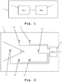
- FIG. 1 an embodiment of the inventive measuring device 1 is shown.
- the inventive measuring device comprises an antenna-element 2 and connected to it processing means 3.
- An electromagnetic signal is received by the antenna-element 2 and processed by the processing means 3.
- the processing means 3 determine the direction and the direction uncertainty and display them.
- Fig. 2 Regarding the construction and function of the antenna-element 2, it is referred to Fig. 2 .
- Fig. 3 - Fig. 5 Regarding the construction and function of the processing means 3, it is referred to Fig. 3 - Fig. 5 .
- the electromagnetic signals detected by the inventive measuring device or inventive measuring method are, for example, radar pulses or radio transmissions.
- Fig. 2 shows the inner workings of the antenna-element 2 of Fig. 1 .
- the antenna-element 2 comprises a plurality of antennas 20-25, which each are connected to multiplexing means 26.
- the multiplexing means 26 are set up for connecting a number of antennas out of the total available antennas 20-25 to the processing means 3 of Fig. 1 .
- the number of connected antennas can be pre-specified or can be set by the processing means 3.
- antennas 20, 23 and 24 are connected by the multiplexing means 26 to the processing means 3 of Fig. 1 .
- a receiving angle ⁇ is achieved. Within this angle, the direction of incoming electromagnetic signals can be determined.
- the multiplexing means 26 can be omitted.
- the antenna-element 2 merely comprises the antennas 20-25.
- the antenna-element 2 comprises at least two different antennas 20 - 25. Alternatively, at least five different antennas are present. Alternatively, at least ten different antennas are present.
- At least the signals of two antennas have to be used.
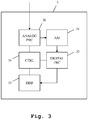
- the processing means 3 comprise analog processing means 30, which are supplied with the signal of antenna-element 2 of Fig. 1 .
- the processing means 3 comprise an analog-digital-converter 31, which is connected to the analog processing means 30.
- the analog-digital-converter 31, again, is connected to digital processing means 32, which are connected to display means 33.
- the analog processing means 30, the digital processing means 32 and the display means 33 are connected to control means 34, which are set up for controlling these components.
- the measuring device 1, more accurately the processing means 3 do not comprise display means 33.
- the results of the digital processing means 32 especially the direction and the direction uncertainty and optionally a direction quality are output over an interface, for example a local area network (LAN).
- LAN local area network
- These results can then be used, processed and displayed by any connected device.
- the results are then output using a predefined format, which can easily be used by other devices. For example the format "pulse description word" (PDW) is used.
- PGW pulse description word
- Signals from the antenna-elements 2 are received by the analog processing means 30. These signals comprise the signals of the individual antennas 20-25 of Fig. 2 or of some of these antennas which are currently connected to the analog processing means 30 by use of the multiplexing means 26. Alternatively, the signals of all antennas 20-25 of Fig. 20 can be transmitted to the analog processing means 30.
- the signal to be received by the analog processing means 30 is processed by them. For example, an amplification and a power determination can be performed.
- the resulting signals are handed on to the analog-digital converter 31, which digitizes the signals.
- the digitized signals are passed to the digital processing means 32, which perform digital processing.
- the digital processing means 32 perform a determination of the direction of the detected electromagnetic signal.
- the digital processing means 32 determine a direction uncertainty angle of the direction of the electromagnetic signal.
- the digital processing means 32 of Fig. 3 comprise direction detection means 320, which are connected to the analog-digital-converter 31 of Fig. 3 and to the display means 33 of Fig. 3 . Furthermore, the digital processing means 32 comprise a direction databank 321, which is connected to the direction detection means 320. Moreover, the digital processing means 32 comprise direction uncertainty determination means 322, which are also connected to the direction determination means 320. Moreover, the direction uncertainty determination means 322 are also connected to the display means 33 of Fig. 3 .
- the direction database 321 holds pre-stored data linking antenna-element output signals to directions of received electromagnetic signals. Parameters stored within the direction database 321 are for example received power of each individual antenna, timing of the reception of the signal by the individual antenna and received frequency of the signal at the individual antennas. These parameters are stored for each pre-stored signal source, defined by its direction in azimuth and elevation, its polarization and its frequency.
- the direction determination means 320 and the direction uncertainty determination means 322 are advantageously constructed as a FPGA (field programmable gate array) or several FPGAs working in parallel.
- the direction uncertainty angle is determined by the direction uncertainty determination means 322.
- the search function used for determining the direction is again used.
- the search function results in a minimum, which indicates the closest match to a direction within the direction databank 321.
- the direction uncertainty angle is determined from the steepness of the search function in the area of this minimum. Especially, an angular distance of two samples of the search function having a preset distance of respective search function values to a search function value of the direction of the electromagnetic signal is calculated.
- the direction uncertainty angle is low for a high steepness of the search function in the area of the minimum, while it is high for a low steepness of the search function in the area of the minimum.
- the electromagnetic signal is sampled by several antennas forming an antenna-group as described earlier, for example the three antennas.
- each antenna-group is subjected to an initial measurement, with defined electromagnetic signals of defined direction in azimuth and elevation and defined frequency and polarization.
- this measurement error is not to be confused with the direction uncertainty angle.
- it can be additionally displayed. For example it can be displayed as a probability of correctness of each detected direction.
- a search function is now calculated.
- a ⁇ 2 function is used.
- a maximum likelihood function or a function based upon a noise-density can also be used.
- ⁇ 2 ⁇ ⁇ ⁇ ⁇ k , l k ⁇ l r ref , kl ⁇ ⁇ f ⁇ ⁇ r mess , kl 2 r ref , kl ⁇ ⁇ f ⁇ + ⁇ 2 r mess , kl + ⁇ k , l k ⁇ l ⁇ ref , kl ⁇ ⁇ f ⁇ ⁇ ⁇ mess , kl 2 ⁇ ⁇ ref , kl ⁇ ⁇ f ⁇ + ⁇ 2 ⁇ ⁇ mess , kl
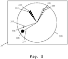
- a display content to be displayed by the display means 33 of Fig. 3 is shown.
- the display 33 shows a circle 339 indicating the search area. Using a shading, or a series of lines, a certain area of the circle 339 can be depicted as the presently active search angle, which has been selected through the antenna selection performed by the multiplexing means 26 of Fig. 2 . This feature though is not depicted here for reasons of simplicity of the figure.
- a first direction is shown by use of an arrow 331 originating from the center of the circle 339 pointing into the direction, in which the electromagnetic signal was detected.
- the length of the arrow 331 corresponds to a probability of the displayed direction being correct. This probability of correctness can be derived from the value of the search function at the detected minimum. For example, it can be determined by multiplying this value of the search function with a weighting parameter.
- the direction uncertainty angle is displayed here by use of lines 332, originating from the center of the circle 339 and progressing alongside the arrow 331.
- the distance of the lines 332 to the arrow 331 indicates the direction uncertainty angle.
- a second direction is shown by a line 333, which points into the direction detected.
- a shaded area 334 is displayed indicating the direction uncertainty angle.
- different colors or different patterns can be used for indicating the direction uncertainty angle.
- a probability of the detected direction can be shown by using a shading which loses intensity, as the distance to the line 333 decreases.
- the length of the lines 335, 337 correspond to the probability of the individual detected direction being correct. In case such a detected direction is not correct, it can be due to a high noise or to reflections.
- the length of the lines 333, 335, 337 and arrows 331 can also be proportional to a received signal power or to the inverse of the received signal power or a distance of the signal source or the inverse of the distance of the signal source. In a further alternative, all lengths of lines 333, 335, 337 and arrows 331 are identical.
- a number of antennas out of the total number of available antennas are selected for processing.
- This step 100 is an optional step. At least two antennas have to be used for being able to detect a direction of an incoming signal. Using more antennas at the same time leads to higher accuracy of detection but significantly increases the necessary processing power. Furthermore, by selecting a higher number of antennas used, a larger search angle ⁇ as depicted in Fig. 2 can be achieved.
- a measurement is performed.
- the signal detected by each employed antenna is recorded.
- a direction is calculated from the received signals.
- a comparison of the received signals with pre-stored signals and corresponding directions is performed.
- a search function is used. The minimum of this search function results in the detected direction.
- a direction uncertainty is calculated by determining the steepness of the search function in the area of the detected minimum. From this steepness, the direction uncertainty angle is calculated.
- the detected direction and the detected direction uncertainty angle are displayed. Regarding the actual processing, it is referred to the elaborations regarding Figs. 2-5 .
- the invention is not limited to certain types of electromagnetic signals. Also the invention is not limited to a specific number of antennas.
Landscapes
- Physics & Mathematics (AREA)
- Engineering & Computer Science (AREA)
- General Physics & Mathematics (AREA)
- Radar, Positioning & Navigation (AREA)
- Remote Sensing (AREA)
- Variable-Direction Aerials And Aerial Arrays (AREA)
- Radar Systems Or Details Thereof (AREA)
Claims (12)
- Messvorrichtung zur Ermittlung der Richtung eines elektromagnetischen Signals, umfassend:- ein Antennenelement (2) mit zumindest zwei Antennen (20-25) zum Empfangen des elektromagnetischen Signals,- eine Anzeigeeinrichtung (33),- eine Verarbeitungseinrichtung (3) zum Bestimmen der Richtung des elektromagnetischen Signals- und eine Richtungsunsicherheits-Bestimmungseinrichtung (322) zum Bestimmen eines Richtungsunsicherheitswinkels der Richtung des elektromagnetischen Signals,wobei die Verarbeitungseinrichtung (3) eingerichtet ist- zur Anzeige eines ersten Kreises (339), der einen Suchbereich in der Anzeigeeinrichtung (33) angibt,- zur Anzeige der Richtung des elektromagnetischen Signals als Linie (335, 337), die in der Anzeigeeinrichtung (33) in der Mitte des ersten Kreises (339) ihren Ursprung hat und die in die Richtung des elektromagnetischen Signals zeigt,- und zur Anzeige des Richtungsunsicherheitswinkels als einen zweiten Kreis (336, 338), der in der Anzeigeeinrichtung das Ende der genannten Linie (335, 337) mit dem Ursprung der Linie verbindet, die sich in der Mitte des ersten Kreises befindet, wobei die Größe des zweiten Kreises den Richtungsunsicherheitswinkel angibt.
- Messvorrichtung nach Anspruch 1,
dadurch gekennzeichnet, dass die Verarbeitungseinrichtung eine Richtungs-Datenbank (321) umfasst, die vorgespeicherte Daten enthält, welche Antennenelement-Ausgangssignale mit Richtungen von elektromagnetischen Signalen verbinden,
und dass die Verarbeitungseinrichtung (3) eingestellt ist zum Bestimmen der Richtung des elektromagnetischen Signals durch Ausführen einer Suche nach einer am nächsten kommenden Übereinstimmung der aus dem elektromagnetischen Signal resultierenden Antennenelement-Ausgangssignale mit den in der Richtungs-Datenbank (321) vorgespeicherten Antennenelement-Ausgangssignalen. - Messvorrichtung nach Anspruch 2,
dadurch gekennzeichnet, dass die Suche unter Heranziehung einer Suchfunktion ausgeführt wird und dass die Suchfunktion eine χ2-Funktion oder eine Maximal-Likelihood-Funktion ist oder auf einer Rauschdichte basiert. - Messvorrichtung nach Anspruch 3,
dadurch gekennzeichnet, dass die Richtungsunsicherheits-Bestimmungseinrichtung (322) eingestellt ist zum Bestimmen des Richtungsunsicherheitswinkels aus der Suchfunktion. - Messvorrichtung nach Anspruch 4,
dadurch gekennzeichnet, dass die Richtungsunsicherheits-Bestimmungseinrichtung (322) eingestellt ist zum Bestimmen des Richtungsunsicherheitswinkels aus der Suchfunktion durch Bestimmen einer Steilheit der Suchfunktion in der Richtung des elektromagnetischen Signals. - Messvorrichtung nach einem der Ansprüche 3 bis 5,
dadurch gekennzeichnet, dass die Richtungsunsicherheits-Bestimmungseinrichtung (322) eingestellt ist zum Bestimmen des Richtungsunsicherheitswinkels aus der Suchfunktion durch Bestimmen eines Winkelabstands zweier Abtastproben der Suchfunktion, die einen vorgegebenen Abstand der jeweiligen Suchfunktionswerte zu einem Suchfunktionswert der Richtung des elektromagnetischen Signals aufweisen. - Verfahren zur Ermittlung der Richtung eines elektromagnetischen Signals mit folgenden Schritten:- Bestimmen der Richtung des elektromagnetischen Signals,- Anzeigen eines ersten Kreises (339), der einen Suchbereich angibt,- Anzeigen der Richtung des elektromagnetischen Signals als Linie (335, 337), die in der Mitte des ersten Kreises (339) ihren Ursprung hat und die in die Richtung des elektromagnetischen Signals zeigt,- Bestimmen eines Richtungsunsicherheitswinkels der Richtung des elektromagnetischen Signals- und Anzeigen des Richtungsunsicherheitswinkels als zweiten Kreis (336, 338), der das Ende der geraden Linie (335, 337) mit dem in der Mitte des ersten Kreises befindlichen Ursprung der Linie verbindet, wobei die Größe des zweiten Kreises den Richtungsunsicherheitswinkel angibt.
- Verfahren nach Anspruch 7,
dadurch gekennzeichnet, dass das Verfahren ein Bestimmen der Richtung des elektromagnetischen Signals durch Ausführen einer Suche nach einer am nächsten kommenden Übereinstimmung von aus dem elektromagnetischen Signal resultierenden vorliegenden Antennenelement-Ausgangssignalen und vorgespeicherten Daten umfasst, die Antennenelement-Ausgangssignale mit Richtungen von elektromagnetischen Signalen innerhalb einer Richtungs-Datenbank (321) verbinden. - Verfahren nach Anspruch 8,
dadurch gekennzeichnet, dass die Suche unter Heranziehung einer Suchfunktion durchgeführt wird und dass die Suchfunktion eine χ2-Funktion oder eine Maximal-Likelihood-Funktion ist oder auf einer Rauschdichte basiert. - Verfahren nach Anspruch 9,
dadurch gekennzeichnet, dass das Verfahren ein Bestimmen des Richtungsunsicherheitswinkels aus der Suchfunktion umfasst. - Verfahren nach Anspruch 9 oder 10,
dadurch gekennzeichnet, dass das Verfahren ein Bestimmen des Richtungsunsicherheitswinkels aus der Suchfunktion durch Bestimmen einer Steilheit der Suchfunktion in der Richtung des elektromagnetischen Signals umfasst. - Verfahren nach einem der Ansprüche 9 bis 11,
dadurch gekennzeichnet, dass das Verfahren ein Bestimmen des Richtungsunsicherheitswinkels aus der Suchfunktion durch Bestimmen eines Winkelabstands zweier Abtastproben der Suchfunktion umfasst, die einen zuvor festgelegten Abstand der jeweiligen Suchfunktionswerte zu einem Suchfunktionswert der Richtung des elektromagnetischen Signals aufweisen.
Applications Claiming Priority (1)
| Application Number | Priority Date | Filing Date | Title |
|---|---|---|---|
| PCT/EP2013/054370 WO2014135196A1 (en) | 2013-03-05 | 2013-03-05 | Measuring device and measuring method for direction finding and direction uncertainty determination |
Publications (2)
| Publication Number | Publication Date |
|---|---|
| EP2965108A1 EP2965108A1 (de) | 2016-01-13 |
| EP2965108B1 true EP2965108B1 (de) | 2017-11-29 |
Family
ID=47882137
Family Applications (1)
| Application Number | Title | Priority Date | Filing Date |
|---|---|---|---|
| EP13709178.1A Active EP2965108B1 (de) | 2013-03-05 | 2013-03-05 | Messvorrichtung und messverfahren zur richtungsfindung und zur bestimmung von richtungsunsicherheiten |
Country Status (5)
| Country | Link |
|---|---|
| US (1) | US9958525B2 (de) |
| EP (1) | EP2965108B1 (de) |
| CN (1) | CN105008950B (de) |
| ES (1) | ES2659735T3 (de) |
| WO (1) | WO2014135196A1 (de) |
Families Citing this family (4)
| Publication number | Priority date | Publication date | Assignee | Title |
|---|---|---|---|---|
| EP3147683B8 (de) | 2015-09-24 | 2020-08-12 | Rohde & Schwarz GmbH & Co. KG | Messvorrichtung und messverfahren zur systematischen fehlererkennung |
| EP3351957B8 (de) | 2017-01-20 | 2021-12-29 | Rohde & Schwarz GmbH & Co. KG | Verfahren und vorrichtung zur richtungsfindung mit richtungsbeurteilung |
| US10931352B2 (en) | 2018-10-12 | 2021-02-23 | Nec Corporation | Efficient beam search and data communication in millimeter-wave wireless networks |
| US20210349177A1 (en) * | 2020-05-08 | 2021-11-11 | 7hugs Labs SAS | Low profile pointing device |
Family Cites Families (16)
| Publication number | Priority date | Publication date | Assignee | Title |
|---|---|---|---|---|
| US3059233A (en) * | 1959-11-27 | 1962-10-16 | Louis S Guarino | Horizontal display |
| US4203667A (en) * | 1978-12-04 | 1980-05-20 | The United States Of America As Represented By The Secretary Of The Navy | Covert recovery or signalling system |
| US5173709A (en) * | 1991-06-03 | 1992-12-22 | Motorola, Inc. | Electronic direction finder |
| DE19925580B4 (de) * | 1999-06-04 | 2010-09-09 | Eads Deutschland Gmbh | Pegel- und Peilwinkel-basierte Detektion und Segmentierung von Sendungen im HF-Bereich |
| US6895329B1 (en) * | 2000-10-30 | 2005-05-17 | Board Of Trustees Of The University Of Illinois | Method and system for querying in a moving object database |
| US7408509B2 (en) * | 2003-02-24 | 2008-08-05 | Agilent Technologies, Inc | Direction finding method and system using probabilistic mapping |
| DE102004020276A1 (de) | 2004-04-26 | 2005-11-17 | Rohde & Schwarz Gmbh & Co Kg | Verfahren und Vorrichtung zur Funkpeilung mehrerer spektral überlappender Funkstationen |
| EP1746433B1 (de) * | 2005-07-18 | 2007-08-29 | Gerald Kampel | Verfahren und Vorrichtung zum Auffinden eines Verschütteten |
| US20070290924A1 (en) * | 2005-12-14 | 2007-12-20 | Innerwireless, Inc. | Wireless resource monitoring system and method |
| CN101206257B (zh) * | 2006-12-20 | 2011-09-21 | 深圳职业技术学院 | 一种空降兵集结通信系统及方法 |
| WO2008112765A1 (en) * | 2007-03-15 | 2008-09-18 | Compass Auto Tracker Llc | An apparatus and method for a directional finder |
| US8199053B2 (en) * | 2007-10-31 | 2012-06-12 | Agilent Technologies, Inc. | Three dimensional RF search system |
| US8504322B2 (en) * | 2008-12-01 | 2013-08-06 | Agilent Technologies, Inc. | Likelihood map system for localizing an emitter |
| US7978139B2 (en) | 2009-06-18 | 2011-07-12 | Bae Systems Information And Electronic Systems Integration Inc. | Direction finding and geolocation of wireless devices |
| JP2011028660A (ja) * | 2009-07-29 | 2011-02-10 | Fujitsu Semiconductor Ltd | 半導体装置、無線タグおよび方向判定方法 |
| US8405550B2 (en) * | 2010-07-30 | 2013-03-26 | Raytheon Applied Signal Technology, Inc. | Near-vertical direction finding and geolocation system |
-
2013
- 2013-03-05 EP EP13709178.1A patent/EP2965108B1/de active Active
- 2013-03-05 WO PCT/EP2013/054370 patent/WO2014135196A1/en not_active Ceased
- 2013-03-05 ES ES13709178.1T patent/ES2659735T3/es active Active
- 2013-03-05 US US14/772,666 patent/US9958525B2/en active Active
- 2013-03-05 CN CN201380074306.5A patent/CN105008950B/zh active Active
Also Published As
| Publication number | Publication date |
|---|---|
| CN105008950A (zh) | 2015-10-28 |
| EP2965108A1 (de) | 2016-01-13 |
| US9958525B2 (en) | 2018-05-01 |
| CN105008950B (zh) | 2017-06-16 |
| ES2659735T3 (es) | 2018-03-19 |
| US20160018506A1 (en) | 2016-01-21 |
| WO2014135196A1 (en) | 2014-09-12 |
Similar Documents
| Publication | Publication Date | Title |
|---|---|---|
| US10871551B2 (en) | Least squares fit classifier for improved sensor performance | |
| KR101137793B1 (ko) | 방향 탐지 시스템, 장치 및 방법 | |
| US9958525B2 (en) | Measuring device and measuring method for direction finding and direction uncertainty determination | |
| KR101697696B1 (ko) | 지향성 안테나를 이용한 방향 탐지 방법 및 장치 | |
| JP2010181985A (ja) | 船舶搭載用航行支援システム | |
| RU2235342C2 (ru) | Способ измерения угловых координат объекта и радиолокационная станция для его реализации | |
| JP6215543B2 (ja) | レーダ装置 | |
| CN104768175B (zh) | 一种区域网络覆盖检测方法及系统 | |
| US11546084B2 (en) | Signal detection by means of supplemental information | |
| EP3306342A1 (de) | Zieldetektor und zieldetektionsverfahren | |
| US20160231416A1 (en) | Method and system for determining a reception configuration and a duration of a time interval | |
| EP3147683B1 (de) | Messvorrichtung und messverfahren zur systematischen fehlererkennung | |
| US10348361B2 (en) | Measuring device and method for phase-coherent analysis of frequency-hopping signals | |
| EP3351957B1 (de) | Verfahren und vorrichtung zur richtungsfindung mit richtungsbeurteilung | |
| JP6147617B2 (ja) | レーダ装置及びその信号処理方法 | |
| EP2344903B1 (de) | Verfahren zur schätzung der polarisationselliptizität eines antennenantwortsignals auf eine einfallende elektromagnetische welle | |
| JP4911571B2 (ja) | 電波発射源可視化装置及びその方法 | |
| CN110703247A (zh) | 一种波位信息检测方法、波位信息检测装置和存储介质 | |
| US20240385285A1 (en) | Radar pulse compression | |
| Li et al. | Beach soil moisture measurement with a land reflected GPS bistatic radar technique | |
| RU2309427C1 (ru) | Способ измерения угловых координат объекта и радиолокационная станция для его реализации | |
| US11262450B1 (en) | Receive only ionosonde using broadband emissions as signals of opportunity | |
| Wyatt | Improving the quality control and accuracy of HF radar currents | |
| JP5007414B2 (ja) | 高速フーリエ変換と加算平均による速度の測定方法 | |
| RU2610304C1 (ru) | Способ обнаружения радиолокационных сигналов и радиолокационная станция для его осуществления |
Legal Events
| Date | Code | Title | Description |
|---|---|---|---|
| PUAI | Public reference made under article 153(3) epc to a published international application that has entered the european phase |
Free format text: ORIGINAL CODE: 0009012 |
|
| 17P | Request for examination filed |
Effective date: 20150619 |
|
| AK | Designated contracting states |
Kind code of ref document: A1 Designated state(s): AL AT BE BG CH CY CZ DE DK EE ES FI FR GB GR HR HU IE IS IT LI LT LU LV MC MK MT NL NO PL PT RO RS SE SI SK SM TR |
|
| AX | Request for extension of the european patent |
Extension state: BA ME |
|
| DAX | Request for extension of the european patent (deleted) | ||
| RIC1 | Information provided on ipc code assigned before grant |
Ipc: G01S 3/04 20060101AFI20170505BHEP Ipc: G01S 3/28 20060101ALI20170505BHEP Ipc: G01S 3/46 20060101ALN20170505BHEP Ipc: G01S 3/74 20060101ALI20170505BHEP |
|
| GRAP | Despatch of communication of intention to grant a patent |
Free format text: ORIGINAL CODE: EPIDOSNIGR1 |
|
| STAA | Information on the status of an ep patent application or granted ep patent |
Free format text: STATUS: GRANT OF PATENT IS INTENDED |
|
| INTG | Intention to grant announced |
Effective date: 20170616 |
|
| GRAS | Grant fee paid |
Free format text: ORIGINAL CODE: EPIDOSNIGR3 |
|
| GRAA | (expected) grant |
Free format text: ORIGINAL CODE: 0009210 |
|
| STAA | Information on the status of an ep patent application or granted ep patent |
Free format text: STATUS: THE PATENT HAS BEEN GRANTED |
|
| AK | Designated contracting states |
Kind code of ref document: B1 Designated state(s): AL AT BE BG CH CY CZ DE DK EE ES FI FR GB GR HR HU IE IS IT LI LT LU LV MC MK MT NL NO PL PT RO RS SE SI SK SM TR |
|
| REG | Reference to a national code |
Ref country code: CH Ref legal event code: EP |
|
| REG | Reference to a national code |
Ref country code: AT Ref legal event code: REF Ref document number: 950886 Country of ref document: AT Kind code of ref document: T Effective date: 20171215 |
|
| REG | Reference to a national code |
Ref country code: IE Ref legal event code: FG4D |
|
| REG | Reference to a national code |
Ref country code: DE Ref legal event code: R096 Ref document number: 602013030062 Country of ref document: DE |
|
| REG | Reference to a national code |
Ref country code: FR Ref legal event code: PLFP Year of fee payment: 6 |
|
| REG | Reference to a national code |
Ref country code: ES Ref legal event code: FG2A Ref document number: 2659735 Country of ref document: ES Kind code of ref document: T3 Effective date: 20180319 |
|
| REG | Reference to a national code |
Ref country code: NL Ref legal event code: MP Effective date: 20171129 |
|
| REG | Reference to a national code |
Ref country code: LT Ref legal event code: MG4D |
|
| REG | Reference to a national code |
Ref country code: AT Ref legal event code: MK05 Ref document number: 950886 Country of ref document: AT Kind code of ref document: T Effective date: 20171129 |
|
| PG25 | Lapsed in a contracting state [announced via postgrant information from national office to epo] |
Ref country code: LT Free format text: LAPSE BECAUSE OF FAILURE TO SUBMIT A TRANSLATION OF THE DESCRIPTION OR TO PAY THE FEE WITHIN THE PRESCRIBED TIME-LIMIT Effective date: 20171129 Ref country code: NO Free format text: LAPSE BECAUSE OF FAILURE TO SUBMIT A TRANSLATION OF THE DESCRIPTION OR TO PAY THE FEE WITHIN THE PRESCRIBED TIME-LIMIT Effective date: 20180228 Ref country code: SE Free format text: LAPSE BECAUSE OF FAILURE TO SUBMIT A TRANSLATION OF THE DESCRIPTION OR TO PAY THE FEE WITHIN THE PRESCRIBED TIME-LIMIT Effective date: 20171129 Ref country code: FI Free format text: LAPSE BECAUSE OF FAILURE TO SUBMIT A TRANSLATION OF THE DESCRIPTION OR TO PAY THE FEE WITHIN THE PRESCRIBED TIME-LIMIT Effective date: 20171129 |
|
| PG25 | Lapsed in a contracting state [announced via postgrant information from national office to epo] |
Ref country code: LV Free format text: LAPSE BECAUSE OF FAILURE TO SUBMIT A TRANSLATION OF THE DESCRIPTION OR TO PAY THE FEE WITHIN THE PRESCRIBED TIME-LIMIT Effective date: 20171129 Ref country code: RS Free format text: LAPSE BECAUSE OF FAILURE TO SUBMIT A TRANSLATION OF THE DESCRIPTION OR TO PAY THE FEE WITHIN THE PRESCRIBED TIME-LIMIT Effective date: 20171129 Ref country code: BG Free format text: LAPSE BECAUSE OF FAILURE TO SUBMIT A TRANSLATION OF THE DESCRIPTION OR TO PAY THE FEE WITHIN THE PRESCRIBED TIME-LIMIT Effective date: 20180228 Ref country code: HR Free format text: LAPSE BECAUSE OF FAILURE TO SUBMIT A TRANSLATION OF THE DESCRIPTION OR TO PAY THE FEE WITHIN THE PRESCRIBED TIME-LIMIT Effective date: 20171129 Ref country code: AT Free format text: LAPSE BECAUSE OF FAILURE TO SUBMIT A TRANSLATION OF THE DESCRIPTION OR TO PAY THE FEE WITHIN THE PRESCRIBED TIME-LIMIT Effective date: 20171129 Ref country code: GR Free format text: LAPSE BECAUSE OF FAILURE TO SUBMIT A TRANSLATION OF THE DESCRIPTION OR TO PAY THE FEE WITHIN THE PRESCRIBED TIME-LIMIT Effective date: 20180301 |
|
| PG25 | Lapsed in a contracting state [announced via postgrant information from national office to epo] |
Ref country code: NL Free format text: LAPSE BECAUSE OF FAILURE TO SUBMIT A TRANSLATION OF THE DESCRIPTION OR TO PAY THE FEE WITHIN THE PRESCRIBED TIME-LIMIT Effective date: 20171129 |
|
| PG25 | Lapsed in a contracting state [announced via postgrant information from national office to epo] |
Ref country code: CZ Free format text: LAPSE BECAUSE OF FAILURE TO SUBMIT A TRANSLATION OF THE DESCRIPTION OR TO PAY THE FEE WITHIN THE PRESCRIBED TIME-LIMIT Effective date: 20171129 Ref country code: SK Free format text: LAPSE BECAUSE OF FAILURE TO SUBMIT A TRANSLATION OF THE DESCRIPTION OR TO PAY THE FEE WITHIN THE PRESCRIBED TIME-LIMIT Effective date: 20171129 Ref country code: EE Free format text: LAPSE BECAUSE OF FAILURE TO SUBMIT A TRANSLATION OF THE DESCRIPTION OR TO PAY THE FEE WITHIN THE PRESCRIBED TIME-LIMIT Effective date: 20171129 Ref country code: CY Free format text: LAPSE BECAUSE OF FAILURE TO SUBMIT A TRANSLATION OF THE DESCRIPTION OR TO PAY THE FEE WITHIN THE PRESCRIBED TIME-LIMIT Effective date: 20171129 Ref country code: DK Free format text: LAPSE BECAUSE OF FAILURE TO SUBMIT A TRANSLATION OF THE DESCRIPTION OR TO PAY THE FEE WITHIN THE PRESCRIBED TIME-LIMIT Effective date: 20171129 |
|
| REG | Reference to a national code |
Ref country code: DE Ref legal event code: R097 Ref document number: 602013030062 Country of ref document: DE |
|
| PG25 | Lapsed in a contracting state [announced via postgrant information from national office to epo] |
Ref country code: PL Free format text: LAPSE BECAUSE OF FAILURE TO SUBMIT A TRANSLATION OF THE DESCRIPTION OR TO PAY THE FEE WITHIN THE PRESCRIBED TIME-LIMIT Effective date: 20171129 Ref country code: SM Free format text: LAPSE BECAUSE OF FAILURE TO SUBMIT A TRANSLATION OF THE DESCRIPTION OR TO PAY THE FEE WITHIN THE PRESCRIBED TIME-LIMIT Effective date: 20171129 Ref country code: RO Free format text: LAPSE BECAUSE OF FAILURE TO SUBMIT A TRANSLATION OF THE DESCRIPTION OR TO PAY THE FEE WITHIN THE PRESCRIBED TIME-LIMIT Effective date: 20171129 Ref country code: IT Free format text: LAPSE BECAUSE OF FAILURE TO SUBMIT A TRANSLATION OF THE DESCRIPTION OR TO PAY THE FEE WITHIN THE PRESCRIBED TIME-LIMIT Effective date: 20171129 |
|
| PLBE | No opposition filed within time limit |
Free format text: ORIGINAL CODE: 0009261 |
|
| STAA | Information on the status of an ep patent application or granted ep patent |
Free format text: STATUS: NO OPPOSITION FILED WITHIN TIME LIMIT |
|
| REG | Reference to a national code |
Ref country code: CH Ref legal event code: PL |
|
| 26N | No opposition filed |
Effective date: 20180830 |
|
| PG25 | Lapsed in a contracting state [announced via postgrant information from national office to epo] |
Ref country code: SI Free format text: LAPSE BECAUSE OF FAILURE TO SUBMIT A TRANSLATION OF THE DESCRIPTION OR TO PAY THE FEE WITHIN THE PRESCRIBED TIME-LIMIT Effective date: 20171129 Ref country code: MC Free format text: LAPSE BECAUSE OF FAILURE TO SUBMIT A TRANSLATION OF THE DESCRIPTION OR TO PAY THE FEE WITHIN THE PRESCRIBED TIME-LIMIT Effective date: 20171129 |
|
| REG | Reference to a national code |
Ref country code: BE Ref legal event code: MM Effective date: 20180331 |
|
| REG | Reference to a national code |
Ref country code: IE Ref legal event code: MM4A |
|
| PG25 | Lapsed in a contracting state [announced via postgrant information from national office to epo] |
Ref country code: LU Free format text: LAPSE BECAUSE OF NON-PAYMENT OF DUE FEES Effective date: 20180305 |
|
| PG25 | Lapsed in a contracting state [announced via postgrant information from national office to epo] |
Ref country code: IE Free format text: LAPSE BECAUSE OF NON-PAYMENT OF DUE FEES Effective date: 20180305 |
|
| PG25 | Lapsed in a contracting state [announced via postgrant information from national office to epo] |
Ref country code: BE Free format text: LAPSE BECAUSE OF NON-PAYMENT OF DUE FEES Effective date: 20180331 Ref country code: CH Free format text: LAPSE BECAUSE OF NON-PAYMENT OF DUE FEES Effective date: 20180331 Ref country code: LI Free format text: LAPSE BECAUSE OF NON-PAYMENT OF DUE FEES Effective date: 20180331 |
|
| PG25 | Lapsed in a contracting state [announced via postgrant information from national office to epo] |
Ref country code: MT Free format text: LAPSE BECAUSE OF NON-PAYMENT OF DUE FEES Effective date: 20180305 |
|
| PG25 | Lapsed in a contracting state [announced via postgrant information from national office to epo] |
Ref country code: TR Free format text: LAPSE BECAUSE OF FAILURE TO SUBMIT A TRANSLATION OF THE DESCRIPTION OR TO PAY THE FEE WITHIN THE PRESCRIBED TIME-LIMIT Effective date: 20171129 |
|
| PG25 | Lapsed in a contracting state [announced via postgrant information from national office to epo] |
Ref country code: PT Free format text: LAPSE BECAUSE OF FAILURE TO SUBMIT A TRANSLATION OF THE DESCRIPTION OR TO PAY THE FEE WITHIN THE PRESCRIBED TIME-LIMIT Effective date: 20171129 |
|
| PG25 | Lapsed in a contracting state [announced via postgrant information from national office to epo] |
Ref country code: HU Free format text: LAPSE BECAUSE OF FAILURE TO SUBMIT A TRANSLATION OF THE DESCRIPTION OR TO PAY THE FEE WITHIN THE PRESCRIBED TIME-LIMIT; INVALID AB INITIO Effective date: 20130305 Ref country code: MK Free format text: LAPSE BECAUSE OF NON-PAYMENT OF DUE FEES Effective date: 20171129 |
|
| PG25 | Lapsed in a contracting state [announced via postgrant information from national office to epo] |
Ref country code: AL Free format text: LAPSE BECAUSE OF FAILURE TO SUBMIT A TRANSLATION OF THE DESCRIPTION OR TO PAY THE FEE WITHIN THE PRESCRIBED TIME-LIMIT Effective date: 20171129 Ref country code: IS Free format text: LAPSE BECAUSE OF FAILURE TO SUBMIT A TRANSLATION OF THE DESCRIPTION OR TO PAY THE FEE WITHIN THE PRESCRIBED TIME-LIMIT Effective date: 20180329 |
|
| P01 | Opt-out of the competence of the unified patent court (upc) registered |
Effective date: 20230525 |
|
| PGFP | Annual fee paid to national office [announced via postgrant information from national office to epo] |
Ref country code: GB Payment date: 20260324 Year of fee payment: 14 |
|
| PGFP | Annual fee paid to national office [announced via postgrant information from national office to epo] |
Ref country code: DE Payment date: 20260320 Year of fee payment: 14 |
|
| PGFP | Annual fee paid to national office [announced via postgrant information from national office to epo] |
Ref country code: FR Payment date: 20260324 Year of fee payment: 14 |
|
| PGFP | Annual fee paid to national office [announced via postgrant information from national office to epo] |
Ref country code: ES Payment date: 20260420 Year of fee payment: 14 |