EP3306342A1 - Zieldetektor und zieldetektionsverfahren - Google Patents
Zieldetektor und zieldetektionsverfahren Download PDFInfo
- Publication number
- EP3306342A1 EP3306342A1 EP15894079.1A EP15894079A EP3306342A1 EP 3306342 A1 EP3306342 A1 EP 3306342A1 EP 15894079 A EP15894079 A EP 15894079A EP 3306342 A1 EP3306342 A1 EP 3306342A1
- Authority
- EP
- European Patent Office
- Prior art keywords
- target detection
- signal
- target
- range gates
- transmit
- Prior art date
- Legal status (The legal status is an assumption and is not a legal conclusion. Google has not performed a legal analysis and makes no representation as to the accuracy of the status listed.)
- Ceased
Links
Images

Classifications
-
- G—PHYSICS
- G01—MEASURING; TESTING
- G01S—RADIO DIRECTION-FINDING; RADIO NAVIGATION; DETERMINING DISTANCE OR VELOCITY BY USE OF RADIO WAVES; LOCATING OR PRESENCE-DETECTING BY USE OF THE REFLECTION OR RERADIATION OF RADIO WAVES; ANALOGOUS ARRANGEMENTS USING OTHER WAVES
- G01S7/00—Details of systems according to groups G01S13/00, G01S15/00, G01S17/00
- G01S7/02—Details of systems according to groups G01S13/00, G01S15/00, G01S17/00 of systems according to group G01S13/00
- G01S7/28—Details of pulse systems
- G01S7/285—Receivers
- G01S7/292—Extracting wanted echo-signals
- G01S7/2921—Extracting wanted echo-signals based on data belonging to one radar period
-
- G—PHYSICS
- G01—MEASURING; TESTING
- G01S—RADIO DIRECTION-FINDING; RADIO NAVIGATION; DETERMINING DISTANCE OR VELOCITY BY USE OF RADIO WAVES; LOCATING OR PRESENCE-DETECTING BY USE OF THE REFLECTION OR RERADIATION OF RADIO WAVES; ANALOGOUS ARRANGEMENTS USING OTHER WAVES
- G01S13/00—Systems using the reflection or reradiation of radio waves, e.g. radar systems; Analogous systems using reflection or reradiation of waves whose nature or wavelength is irrelevant or unspecified
- G01S13/02—Systems using reflection of radio waves, e.g. primary radar systems; Analogous systems
- G01S13/06—Systems determining position data of a target
- G01S13/08—Systems for measuring distance only
- G01S13/10—Systems for measuring distance only using transmission of interrupted, pulse modulated waves
- G01S13/18—Systems for measuring distance only using transmission of interrupted, pulse modulated waves wherein range gates are used
-
- G—PHYSICS
- G01—MEASURING; TESTING
- G01S—RADIO DIRECTION-FINDING; RADIO NAVIGATION; DETERMINING DISTANCE OR VELOCITY BY USE OF RADIO WAVES; LOCATING OR PRESENCE-DETECTING BY USE OF THE REFLECTION OR RERADIATION OF RADIO WAVES; ANALOGOUS ARRANGEMENTS USING OTHER WAVES
- G01S13/00—Systems using the reflection or reradiation of radio waves, e.g. radar systems; Analogous systems using reflection or reradiation of waves whose nature or wavelength is irrelevant or unspecified
- G01S13/02—Systems using reflection of radio waves, e.g. primary radar systems; Analogous systems
- G01S13/06—Systems determining position data of a target
- G01S13/08—Systems for measuring distance only
- G01S13/10—Systems for measuring distance only using transmission of interrupted, pulse modulated waves
- G01S13/103—Systems for measuring distance only using transmission of interrupted, pulse modulated waves particularities of the measurement of the distance
Definitions
- the present invention relates to a target detection device and the like configured to detect a target by receiving a signal reflected by the target through a pulse-shaped radio wave emitted to the air.
- LPRF low pulse repetition frequency
- HPRF high pulse repetition frequency
- the HPRF radar in which a pulse repetition interval is short and the number of range gates is one or a few at the most, is configured to detect a target by lowering a band frequency for each of the range gates using a digital filter and extracting a Doppler frequency of the target (for example, see Non Patent Literature 1).
- the present invention has been made in view of the foregoing, and has an object to provide a target detection device and the like having improved detectable range performance in which a plurality of range gates are set to be slightly shifted in a time axis direction so that drop of received power is suppressed.
- a target detection device and the like including:
- the plurality of range gates are set at the positions slightly shifted in the time axis direction, and are simultaneously subjected to the processing so that received power from a target is effectively utilized.
- the target detection device and the like having improved detectable range performance can therefore be provided.
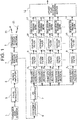
- FIG. 1 is a diagram for illustrating an example of the configuration of a target detection device according to a first embodiment of the present invention.
- the target detection device includes, as illustrated in FIG. 1 , a signal transmit/receive unit including a transmission signal generator 1, a pulse modulator 2, a power amplifier 3, a transmit/receive switch 4, and a transmit/receive antenna 5, and a target detection unit including a frequency converter 6, an A/D converter 7, a plurality of, that is, n (n is an integer of two or more) range gate processing sections (1 to n) 8 1 to 8 n , n digital filters 9, n Doppler filters 10, n target detection processing sections 11, and a largest value detection processing section 12 configured to receive, as input, output of each of the target detection processing sections 11.
- a signal transmit/receive unit including a transmission signal generator 1, a pulse modulator 2, a power amplifier 3, a transmit/receive switch 4, and a transmit/receive antenna 5, and a target detection unit including a frequency converter
- a coherent transmission signal is output from the transmission signal generator 1 to be transmitted to the pulse modulator 2.
- the pulse modulator 2 shapes the coherent transmission signal into a pulse shape.
- the power of the signal shaped into the pulse shape is amplified by the power amplifier 3.
- the signal having the amplified power is transmitted to the transmit/receive antenna 5 by the transmit/receive switch 4 at transmission timing, and is then emitted to the air from the transmit/receive antenna 5 as a transmission pulse 21.
- the radio wave emitted to the air is reflected by, for example, a target, and is then received by the transmit/receive antenna 5 as a received signal 22.
- the received signal 22 is transmitted to the frequency converter 6 by the transmit/receive switch 4 at reception timing.
- the received radio frequency (RF) signal is down-converted into an intermediate frequency (IF) band by the frequency converter 6.
- IF intermediate frequency
- the down-converted signal which is an analog signal, is converted by the A/D converter 7 into received data, which is a digital signal.
- the range gate processing sections (1 to n) 8 1 to 8 n have the same interval. However, as illustrated in FIG. 2 referred to later, processing of extracting the received data, which is the digital signal obtained through the conversion by the A/D converter 7, is performed at each of range gates having data acquisition positions that are slightly shifted in terms of time. The extracted signal is transmitted to the digital filter 9.
- the digital filter 9 passes a target having a frequency shifted by a Doppler frequency therethrough to suppress clutter outside the band frequency of the digital filter.
- Output of the digital filter 9 is decomposed to frequency components by the Doppler filter 10.
- the Doppler filter 10 performs, for example, Fast Fourier Transform (FFT) on the target signal having the frequency shifted by the Doppler frequency by the digital filter 9, to thereby divide the target signal into a plurality of frequency domains.
- FFT Fast Fourier Transform
- the target detection processing section 11 performs target detection processing on the output of the Doppler filter 10, to thereby extract a Doppler frequency of the target.
- each of the range gate processing sections (1 to n) 8 1 to 8 n extracts received data indicating that no target exists
- output of the target detection processing sections 11 indicates that nothing is detected.
- any one of the range gate processing sections (1 to n) 8 1 to 8 n extracts received data indicating that a target exists, as output results from the target detection processing sections 11, there are obtained results having the same Doppler frequency and signal intensities that are different from each other depending on a ratio indicating how much the target is included.
- Each of the target detection processing sections 11 outputs a target detection signal having a signal intensity that is variable depending on the ratio of the received data to the range gate in terms of time.
- the largest value detection processing section 12 detects a target detection signal having the largest signal intensity among the target detection signals detected by the respective target detection processing sections 11, and outputs that signal as a target signal indicating the detected target.
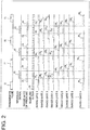
- FIG. 2 is a time chart for illustrating an example of the operation of the target detection device according to the present invention.
- a signal reflected by, for example, a target through the transmission pulse 21 from the transmit/receive antenna 5 is received as the received signal 22.
- a duty ratio between transmission and reception is 33 %
- two range gates having continuous regions on a time axis namely, a range gate 23 and a range gate 24 in the range gate processing section as illustrated in FIG. 2 are used for processing of the received signal 22, that is, received data.
- the received signal 22 is received right in the middle of the reception periods of the range gate 23 and the range gate 24. Consequently, each of the range gates 23 and 24 can receive only half of power from the target, and signal intensities are thus low. As a result, target detection cannot be performed in the maximum detectable range.
- the received signal 22 is input in units of a sampling clock 25, and hence the range gates are set based on the sampling clock.
- a range gate 1 (26 1 ) to a range gate n (26 n ) respectively represent the range gate of the range gate processing section (1) 8 1 to the range gate of the range gate processing section (n) 8 n .
- the timing at which transmission and reception is switched by the transmit/receive switch 4 described above does not necessarily depend on the sampling clock.
- the sampling clock is timing of the digital signal in the A/D conversion, or a clock that has a band frequency lowered by the digital filter, that is, a frequency lower than that of the timing clock of the A/D conversion.
- the time length of the range gate 1 (26 1 ) to the range gate n (26 n ) is the same as the time length of the transmission pulse 21, which is set in advance, in consideration of, for example, the time length of the received signal 22, namely, the received data.
- the range gate 1 (26 1 ) to the range gate n (26 n ) are set to be sequentially shifted from the adjacent range gates in terms of time by the interval of the sampling clock 25, that is, are shifted in the time axis direction so that the adjacent range gates partially overlap each other.
- the signal intensity is the largest.
- the interval of the sampling clock 25 and the shift amount of the positions of the range gates in terms of time match each other.
- the range gates may be thinned out even though some loss occurs in such a case.
- the range gates (1 to n) may be set to be sequentially shifted in terms of time at every set of a plurality of clock intervals of the sampling clock 25.
- the range gates are also set at the positions of the transmission pulse 21, but the range gates may be set not to overlap the transmission pulse 21.
- the range gates are set to be shifted in terms of time in this way, the received signal can be effectively utilized, and large received power can thus be obtained.
- FIG. 3 is a diagram for illustrating an example of the configuration of a target detection device according to a second embodiment of the present invention.
- the second embodiment illustrated in FIG. 3 differs from the first embodiment in the processing of target detection processing sections 13, and the processing of a target detection determination section 14 configured to process output of the target detection processing sections 13.
- the frequency converter 6, the A/D converter 7, the range gate processing sections (1 to n) 8 1 to 8 n , the digital filters 9, the Doppler filters 10, the target detection processing sections 13, and the target detection determination section 14 construct a target detection unit.
- the signal transmit/receive unit including the components from the transmission signal generator 1 to the transmit/receive antenna 5 is similar to that of the first embodiment.
- the components from the frequency converter 6 to the Doppler filters 10, which are configured to process the received signal are also similar to those of the first embodiment.
- the target detection processing section 13 performs target detection processing on output of the Doppler filter 10, to thereby extract a Doppler frequency of a target.
- output of the target detection processing sections 13 indicates that nothing is detected.
- output results from the target detection processing sections 13 have the same Doppler frequency and provide detection results that are different from each other due to signal intensities depending on a ratio indicating how much the target is included.
- Each of the target detection processing sections 13 outputs a detection signal indicating that the target detection is positive when the signal intensity of a target detection signal, which has a signal intensity that is variable depending on the ratio of the received data to the range gate in terms of time, is equal to or more than a determination value set in advance.
- the target detection determination section 14 outputs a target signal indicating that the target detection is positive when at least one of the n target detection processing sections 13 outputs the detection signal indicating that the target detection is positive.
- the second embodiment information on the signal intensity of a target is not obtained, but large received power is obtained with the use of the plurality of range gates similarly to the first embodiment. There is therefore provided an effect of enabling improvement of the detectable range performance.
- the target detection device and the target detection method according to the present invention are applicable to target detection devices used in various fields.
Landscapes
- Engineering & Computer Science (AREA)
- Radar, Positioning & Navigation (AREA)
- Remote Sensing (AREA)
- Computer Networks & Wireless Communication (AREA)
- Physics & Mathematics (AREA)
- General Physics & Mathematics (AREA)
- Radar Systems Or Details Thereof (AREA)
Priority Applications (1)
| Application Number | Priority Date | Filing Date | Title |
|---|---|---|---|
| EP23185249.2A EP4254004A3 (de) | 2015-05-29 | 2015-05-29 | Zieldetektor und zieldetektionsverfahren |
Applications Claiming Priority (1)
| Application Number | Priority Date | Filing Date | Title |
|---|---|---|---|
| PCT/JP2015/065563 WO2016194044A1 (ja) | 2015-05-29 | 2015-05-29 | 目標検出装置および目標検出方法 |
Related Child Applications (1)
| Application Number | Title | Priority Date | Filing Date |
|---|---|---|---|
| EP23185249.2A Division EP4254004A3 (de) | 2015-05-29 | 2015-05-29 | Zieldetektor und zieldetektionsverfahren |
Publications (2)
| Publication Number | Publication Date |
|---|---|
| EP3306342A1 true EP3306342A1 (de) | 2018-04-11 |
| EP3306342A4 EP3306342A4 (de) | 2019-01-23 |
Family
ID=57441060
Family Applications (2)
| Application Number | Title | Priority Date | Filing Date |
|---|---|---|---|
| EP23185249.2A Pending EP4254004A3 (de) | 2015-05-29 | 2015-05-29 | Zieldetektor und zieldetektionsverfahren |
| EP15894079.1A Ceased EP3306342A4 (de) | 2015-05-29 | 2015-05-29 | Zieldetektor und zieldetektionsverfahren |
Family Applications Before (1)
| Application Number | Title | Priority Date | Filing Date |
|---|---|---|---|
| EP23185249.2A Pending EP4254004A3 (de) | 2015-05-29 | 2015-05-29 | Zieldetektor und zieldetektionsverfahren |
Country Status (3)
| Country | Link |
|---|---|
| EP (2) | EP4254004A3 (de) |
| JP (1) | JP6419330B2 (de) |
| WO (1) | WO2016194044A1 (de) |
Cited By (1)
| Publication number | Priority date | Publication date | Assignee | Title |
|---|---|---|---|---|
| US12468012B2 (en) | 2021-03-15 | 2025-11-11 | Mitsubishi Electric Corporation | Radar device |
Families Citing this family (3)
| Publication number | Priority date | Publication date | Assignee | Title |
|---|---|---|---|---|
| JP6523982B2 (ja) * | 2016-02-04 | 2019-06-05 | 三菱電機株式会社 | 目標検出装置 |
| GB2590303B (en) * | 2018-09-13 | 2022-06-22 | Mitsubishi Electric Corp | Radar device and target distance measurement method |
| CN111381229B (zh) * | 2018-12-28 | 2024-05-14 | 松下知识产权经营株式会社 | 推测方法、推测装置以及记录介质 |
Family Cites Families (9)
| Publication number | Priority date | Publication date | Assignee | Title |
|---|---|---|---|---|
| US6420995B1 (en) * | 1965-04-05 | 2002-07-16 | Systems Information And Electronic Systems Integration, Inc. | Radar and IFF system |
| JPS5024079B1 (de) * | 1970-09-25 | 1975-08-13 | ||
| US4328495A (en) * | 1980-04-28 | 1982-05-04 | Honeywell Inc. | Unambiguous doppler radar |
| US4816833A (en) * | 1987-06-16 | 1989-03-28 | Westinghouse Electric Corp. | Pulse doppler surveillance post signal processing and scan to scan correlation |
| IL127650A0 (en) * | 1996-06-28 | 1999-10-28 | Milkovich Systems Engineering | Improved fast fourier transform processor |
| JP3743181B2 (ja) * | 1998-11-16 | 2006-02-08 | 三菱電機株式会社 | パルスドップラレーダ装置 |
| US7379017B2 (en) * | 2006-01-24 | 2008-05-27 | Raytheon Company | Micro movement pulsed radar system and method of phase noise compensation |
| JP5068507B2 (ja) * | 2006-10-26 | 2012-11-07 | 三菱電機株式会社 | 遅延時間推定装置 |
| US7425916B2 (en) * | 2006-11-14 | 2008-09-16 | Stevens Jr Robert R | Airborne distributed pulse doppler radar missile warning system |
-
2015
- 2015-05-29 EP EP23185249.2A patent/EP4254004A3/de active Pending
- 2015-05-29 JP JP2017521318A patent/JP6419330B2/ja active Active
- 2015-05-29 WO PCT/JP2015/065563 patent/WO2016194044A1/ja not_active Ceased
- 2015-05-29 EP EP15894079.1A patent/EP3306342A4/de not_active Ceased
Cited By (1)
| Publication number | Priority date | Publication date | Assignee | Title |
|---|---|---|---|---|
| US12468012B2 (en) | 2021-03-15 | 2025-11-11 | Mitsubishi Electric Corporation | Radar device |
Also Published As
| Publication number | Publication date |
|---|---|
| EP4254004A3 (de) | 2024-04-03 |
| JPWO2016194044A1 (ja) | 2017-10-19 |
| EP3306342A4 (de) | 2019-01-23 |
| WO2016194044A1 (ja) | 2016-12-08 |
| EP4254004A2 (de) | 2023-10-04 |
| JP6419330B2 (ja) | 2018-11-07 |
Similar Documents
| Publication | Publication Date | Title |
|---|---|---|
| EP2584373B1 (de) | Radarvorrichtung | |
| US6335701B1 (en) | Radar system and coherent integrating method thereof | |
| JP2016151425A (ja) | レーダ装置 | |
| EP3208632B1 (de) | Radarvorrichtung und radarverfahren | |
| US9482744B1 (en) | Staggered pulse repetition frequency doppler processing | |
| JP5656505B2 (ja) | レーダ装置 | |
| EP4254004A2 (de) | Zieldetektor und zieldetektionsverfahren | |
| CN114217301A (zh) | 一种高精度边坡监测雷达目标检测及测距方法 | |
| JP2019105601A (ja) | レーダ装置及びそのレーダ信号処理方法 | |
| Qiu et al. | Wideband LPI radar subpulse waveform design, processing, and analysis | |
| US10073170B2 (en) | Radar apparatus | |
| EP3399334A1 (de) | Objektdetektor und sensorvorrichtung | |
| Smith et al. | High power coherent-on-receive radar for marine surveillance | |
| JP6688977B2 (ja) | レーダ装置 | |
| EP3611536A1 (de) | Radarvorrichtung | |
| JP6523982B2 (ja) | 目標検出装置 | |
| JP2004125451A (ja) | パルスレーダ装置 | |
| EP4600695A1 (de) | Radargerät | |
| Youssef et al. | Performance evaluation of time compression overlap-add radar systems based on order-statistics CFAR under convolution noise jamming | |
| Šimon et al. | Single Channel Degarbling of SIF/IFF Pulses Using Spectral Inverse Filtering | |
| US20120032705A1 (en) | Device for Detecting Pulsed Signals Comprising a Function for Detecting Tangling of Pulses | |
| Wang et al. | Detection-jamming integrated waveform design based on multi-dimensional joint constraints | |
| US8587345B2 (en) | Device for detecting pulsed signals with improved sensitivity | |
| RU2421749C1 (ru) | Устройство определения направления | |
| JP2011153958A (ja) | レーダ信号処理装置 |
Legal Events
| Date | Code | Title | Description |
|---|---|---|---|
| STAA | Information on the status of an ep patent application or granted ep patent |
Free format text: STATUS: THE INTERNATIONAL PUBLICATION HAS BEEN MADE |
|
| PUAI | Public reference made under article 153(3) epc to a published international application that has entered the european phase |
Free format text: ORIGINAL CODE: 0009012 |
|
| STAA | Information on the status of an ep patent application or granted ep patent |
Free format text: STATUS: REQUEST FOR EXAMINATION WAS MADE |
|
| 17P | Request for examination filed |
Effective date: 20171228 |
|
| AK | Designated contracting states |
Kind code of ref document: A1 Designated state(s): AL AT BE BG CH CY CZ DE DK EE ES FI FR GB GR HR HU IE IS IT LI LT LU LV MC MK MT NL NO PL PT RO RS SE SI SK SM TR |
|
| AX | Request for extension of the european patent |
Extension state: BA ME |
|
| DAV | Request for validation of the european patent (deleted) | ||
| DAX | Request for extension of the european patent (deleted) | ||
| A4 | Supplementary search report drawn up and despatched |
Effective date: 20181221 |
|
| RIC1 | Information provided on ipc code assigned before grant |
Ipc: G01S 13/18 20060101AFI20181217BHEP Ipc: G01S 13/10 20060101ALI20181217BHEP Ipc: G01S 7/292 20060101ALI20181217BHEP |
|
| STAA | Information on the status of an ep patent application or granted ep patent |
Free format text: STATUS: EXAMINATION IS IN PROGRESS |
|
| 17Q | First examination report despatched |
Effective date: 20210525 |
|
| REG | Reference to a national code |
Ref country code: DE Ref legal event code: R003 |
|
| STAA | Information on the status of an ep patent application or granted ep patent |
Free format text: STATUS: THE APPLICATION HAS BEEN REFUSED |
|
| 18R | Application refused |
Effective date: 20230315 |