EP2964309B1 - Katheterpunktionsbesteck - Google Patents
Katheterpunktionsbesteck Download PDFInfo
- Publication number
- EP2964309B1 EP2964309B1 EP13714347.5A EP13714347A EP2964309B1 EP 2964309 B1 EP2964309 B1 EP 2964309B1 EP 13714347 A EP13714347 A EP 13714347A EP 2964309 B1 EP2964309 B1 EP 2964309B1
- Authority
- EP
- European Patent Office
- Prior art keywords
- catheter
- puncture
- housing
- puncture needle
- branch portion
- Prior art date
- Legal status (The legal status is an assumption and is not a legal conclusion. Google has not performed a legal analysis and makes no representation as to the accuracy of the status listed.)
- Active
Links
Images

Classifications
-
- A—HUMAN NECESSITIES
- A61—MEDICAL OR VETERINARY SCIENCE; HYGIENE
- A61M—DEVICES FOR INTRODUCING MEDIA INTO, OR ONTO, THE BODY; DEVICES FOR TRANSDUCING BODY MEDIA OR FOR TAKING MEDIA FROM THE BODY; DEVICES FOR PRODUCING OR ENDING SLEEP OR STUPOR
- A61M25/00—Catheters; Hollow probes
- A61M25/01—Introducing, guiding, advancing, emplacing or holding catheters
- A61M25/06—Body-piercing guide needles or the like
- A61M25/0662—Guide tubes
- A61M25/0668—Guide tubes splittable, tear apart
-
- A—HUMAN NECESSITIES
- A61—MEDICAL OR VETERINARY SCIENCE; HYGIENE
- A61M—DEVICES FOR INTRODUCING MEDIA INTO, OR ONTO, THE BODY; DEVICES FOR TRANSDUCING BODY MEDIA OR FOR TAKING MEDIA FROM THE BODY; DEVICES FOR PRODUCING OR ENDING SLEEP OR STUPOR
- A61M25/00—Catheters; Hollow probes
- A61M25/01—Introducing, guiding, advancing, emplacing or holding catheters
- A61M25/06—Body-piercing guide needles or the like
- A61M25/0612—Devices for protecting the needle; Devices to help insertion of the needle, e.g. wings or holders
- A61M25/0618—Devices for protecting the needle; Devices to help insertion of the needle, e.g. wings or holders having means for protecting only the distal tip of the needle, e.g. a needle guard
-
- A—HUMAN NECESSITIES
- A61—MEDICAL OR VETERINARY SCIENCE; HYGIENE
- A61M—DEVICES FOR INTRODUCING MEDIA INTO, OR ONTO, THE BODY; DEVICES FOR TRANSDUCING BODY MEDIA OR FOR TAKING MEDIA FROM THE BODY; DEVICES FOR PRODUCING OR ENDING SLEEP OR STUPOR
- A61M25/00—Catheters; Hollow probes
- A61M25/0097—Catheters; Hollow probes characterised by the hub
-
- A—HUMAN NECESSITIES
- A61—MEDICAL OR VETERINARY SCIENCE; HYGIENE
- A61M—DEVICES FOR INTRODUCING MEDIA INTO, OR ONTO, THE BODY; DEVICES FOR TRANSDUCING BODY MEDIA OR FOR TAKING MEDIA FROM THE BODY; DEVICES FOR PRODUCING OR ENDING SLEEP OR STUPOR
- A61M25/00—Catheters; Hollow probes
- A61M25/01—Introducing, guiding, advancing, emplacing or holding catheters
- A61M25/06—Body-piercing guide needles or the like
- A61M25/0693—Flashback chambers
Definitions
- the invention relates to a catheter puncture set according to the preamble of claim 1.
- the vessel (often an artery or vein) into which the catheter is to be inserted is punctured with a hollow puncture needle.
- a guide wire is inserted through the hollow puncture needle into the vessel.
- the hollow needle is then withdrawn over the inner guidewire so that the guidewire can be advanced further into the punctured vessel to initially expand it somewhat using a dilator pushed over the guidewire.
- the actual catheter is inserted over the lying guide wire into the vessel and moved to the desired end position.
- the guidewire is gently withdrawn through the catheter.
- a device for inserting a venous catheter with an insertable into a vein opening guide tube having a dimensioned for receiving the catheter tube inner channel and separable in the longitudinal direction to be removed from the inserted catheter can, wherein the guide tube for the catheter tube by means of a pants-like joint is united with a second guide tube for a puncturing needle to a common guide portion.
- a catheter puncture set is known that simplifies the placement of a catheter by providing the necessary equipment for puncture and the placement of a catheter in a multi-part merged system and thereby manages without a guide wire or additional Dilatations mar.
- the catheter puncture set disclosed therein comprises a tube-like housing with an elongate housing section, which merges into an extension section and from which a branch section branches off at an angle.
- the housing portion and the branch portion have a continuous lateral opening which is closed by a flexible jacket extending along the branch portion and the housing portion, into which a catheter can be inserted.
- the puncture needle extending along the elongated housing portion and the extension portion exits the tip of the housing at the puncture of the vessel and, after puncturing into the housing, is retracted beyond the branching point of the branched portion.
- a blood collection container At the rear end of the puncture needle is a blood collection container.
- the catheter is introduced via the branch section and the housing section out of the housing through the flexible sheath into the punctured vessel to the desired depth. Only then is the catheter puncture set withdrawn from the punctured vessel of the patient. Finally, the flexible sheath is pulled out of the housing or peeled off from the catheter via a lateral longitudinal slot.
- the object of the present invention to provide a catheter puncture set, which ensures that the puncture needle is secured there in a structurally simple and irreversible way after returning to the housing of the catheter puncture set. In this way, a possible infection in this punctured with patient blood puncture needle should be safely excluded.
- the catheter puncture set according to the invention represents a closed, one-piece system, which unites and makes available all components necessary for the puncture in a housing and at the same time makes it possible to detach and expose the catheter after insertion into the punctured vessel with a handle from the catheter puncture set.
- the catheter puncture device housing is integrally formed, wherein the elongated, tubular closed housing portion both leads a puncture needle extending with its tip from the elongated housing portion, extending along the elongate housing portion and the extension portion, as well as the guide channel for the Catheter forms.
- the catheter puncture set comprises, in a single housing, first the puncture needle, which is pushed out of the elongate housing section at one end and punctures the vessel. At the same time, the end of the housing itself is inserted a little into the dotted vessel. If the vessel has been punctured, blood enters the puncture needle, which is received in a preferably transparent blood collection container arranged at the other end of the puncture needle.
- the puncture needle After puncture the puncture needle is withdrawn with the blood collection container located thereon from the vessel, the housing itself remains in the vessel.
- the puncture needle is withdrawn until the tip comes to lie behind the branch of the Abzweigabitess of the housing and abuts a puncture needle arranged stop on a corresponding abutment in the housing, so that the puncture needle can not be completely pulled out of the catheter puncture set.
- a locking element secures the puncture needle, so that their blood-contaminated tip comes to rest securely in the housing and does not pose a risk of injury to medical personnel or other persons.
- this is achieved by an expansion body, the tentacles after spreading a paragraph step inside spread in the tubular housing and thus prevent a forward pushing the puncture needle final.
- This lock is not reversible.
- This spreading body according to the invention with tentacles is attached to the front side of the puncture needle, the orientation of the tentacles causes a return of the puncture needle is readily possible because the tentacles create indeed on the inner shell of the tubular housing, by the Glastownsraum but no blockage of Movement can take place. Only after locking in the appropriate housing level, the tentacles can spread further and thus cause the lock.
- the catheter is introduced via the branch section through the housing into the punctured vessel and pushed into the vessel as far as desired.
- the inserted catheter is then exposed and the catheter puncture set according to the invention can be disposed of with the puncture needle and blood collection container easily and without any risk of injury.
- the catheter until it is pushed into the punctured vessel releasably fixed to an additionally arranged on the housing holder.
- a clamping bracket which is to be solved with one hand. This ensures, on the one hand, that during the actual puncturing the flexible catheter is not a hindrance or is pulled out of the puncture set. On the other hand, this can be easily solved after the puncture of the fixation and inserted into the punctured vessel.
- a further advantageous embodiment of the invention provides two approximately parallel predetermined breaking points, which extend along the branch section to the top of the housing. It is advantageous in this case that their distance from one another defines the width of an opening strip which can be removed from the housing, this width corresponding approximately to that of the catheter to be exposed.
- a tearing device arranged in the region of the branching section is furthermore provided in an expedient design. This is advantageous insofar as the opening of the housing along the predetermined breaking points towards the punctured patient takes place and not away from it. This in turn ensures that the inserted catheter is not inadvertently pulled out of the vessel as the pulling movement on the housing occurs to remove the opening strip towards the patient.
- a tearing device is provided at the predetermined breaking point, which is designed as an at least one-sided gripping surface for a better introduction of tensile force into the predetermined breaking point.
- FIGS. 1 to 4 For more detailed description, an embodiment of the one-piece catheter puncture set according to the invention will be described in detail.
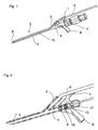
- FIG. 1 shows the catheter puncture set 2 according to the invention consisting of a tubular housing 3 with an elongated housing portion, which merges into an extension portion for guiding the puncture needle 9 with blood collection container 7, stop and blocking element 17, and from the branched off at an angle a branch portion 5, via which a catheter 8 in the elongated housing portion is inserted.
- the new catheter puncture set follows the state of the art.
- the catheter puncture set 2 according to the invention is already considerably narrower in its external appearance than was the case with the designs cited in the prior art. This is realized primarily by the fact that the predetermined breaking points 15, which are only recognizable on one side in the illustrated design, parallel in the concrete structural solution but also on the unrecognizable back of the device, allow both the catheter 8 and the cannula 9 can be performed for puncturing the vessel in the same tubular housing 3.
- the blood collection container 7 which is arranged via a screw connection to the rear housing section 4 with handle 6, does not necessarily have to be present in this illustrated design.
- the blood collection container 7 also by a plugged disposable syringe, for example, a 10 ml syringe, be replaced without the structural functionality is impaired.
- the blood collection container 7 in the structural solution shown here only one possible design.
- a blood collection container 7 is basically any body to understand that can be placed on the catheter puncture set 2 and here prevents leakage of the blood during the puncture.
- FIG. 2 which is a sectional view of the catheter puncture set 2 in the area of the supply of the catheter 8 via the branch portion 5, this double function of the tubular housing 3 of the catheter puncture set 2 becomes very clear. It is here the procedural section in FIG. 2 represented in which the catheter puncture set 2 has already been successfully introduced into a vessel of the patient, which is not shown here pictorially. After this puncture, the cannula 8 can be withdrawn behind the branching section 5 into a rear region 4 of the catheter puncture set 2, where a locking takes place. This locking causes this puncture needle 9 can not be moved forward or further out of the cutlery.
- FIG. 2 In the innovative design, the in FIG. 2 is shown, this is achieved by an expansion body 17, the tentacles 10 spread after exceeding a paragraph step 16 inside the tubular housing 3 and thus prevent a forward pushing the puncture needle 9 final. This lock is not reversible.
- This spreading body 17 according to the invention with tentacles 10 is attached to the front side of the puncture needle 9, wherein the orientation of the tentacles 10 causes a return of the puncture needle 9 is readily possible, since the tentacles 10 while invest in the inner shell of the tubular housing 3, However, by the Switzerlandzisraum no blocking of the movement can take place. Only after locking in the corresponding housing stage 16, the tentacles 10 can continue to spread and thus cause the lock.
- FIG. 2 also shows the front end of the inserted cannula 8, which is inserted in the branch section 5 of the catheter puncture set 2.
- the fixation of the catheter 8 is achieved in this starting position by a holder 1, which fixes the catheter 8 in this position until it is to be inserted into the punctured vessel. It is intended for this purpose to pull the catheter 8 upwards for further insertion from the clamp holder 1 and thus to move it into a movable position. Since the puncture needle 9 is no longer blocking the tube-like housing 3 as a guide for the catheter 8 after the puncture, there is an open guide channel, through which the catheter 8 can now be introduced into the vessel of the patient.
- FIG. 3 shows how to proceed after insertion of the catheter 8 in the dotted patient vessel on. Since the catheter 8 is now placed, the tube-like vessel 3 can be pulled out of the punctured vessel of the patient. However, the catheter 8 is still enclosed in the tubular housing 3 of the catheter puncture set 2 and must first be dissolved out of it. For this purpose, a detachment of an opening strip 13 is provided, which is defined by the two longitudinally extending from the branching point 5 to the tip of the tubular housing 3 predetermined breaking points 15.
- FIG. 3 shows the process of detachment of this opening strip 13, whereby as in FIG. 4 shown the individual components of the catheter puncture set 2 are separated.
- the formerly integrally formed catheter puncture set 2 disintegrates after removing the opening strip 13 in the actual catheter 8, the catheter puncture set 2 with all the way to the stop pulled out puncture needle 9 and elongated outlet opening 11 for the catheter and the opening strip 13, which has exposed the corresponding opening 11.
- the puncture needle 9 remains safely in the catheter puncture set 2 and also the leaked at the puncture blood safely remains in the blood collection container 7, without contamination of the working with the Katherticianionsbesteck 2 staff is to be feared.
- the present safety cannula with locking fulfills the corresponding requirements of the Medical Devices Act.
- the detachment of the opening strip 13 at the parallel predetermined breaking points 15 along the tubular housing 3 is facilitated by gripping surfaces 12 in the region of the branch section 5. These on both sides of the catheter puncture set 2 branching wing-like gripping surfaces 12 allow easy gripping this area, for example, between thumb and forefinger, whereby the risk of unintentional withdrawal of the already in the vessel located catheter 8 can be further reduced.
Landscapes
- Health & Medical Sciences (AREA)
- Life Sciences & Earth Sciences (AREA)
- Biophysics (AREA)
- Pulmonology (AREA)
- Engineering & Computer Science (AREA)
- Anesthesiology (AREA)
- Biomedical Technology (AREA)
- Heart & Thoracic Surgery (AREA)
- Hematology (AREA)
- Animal Behavior & Ethology (AREA)
- General Health & Medical Sciences (AREA)
- Public Health (AREA)
- Veterinary Medicine (AREA)
- Media Introduction/Drainage Providing Device (AREA)
- Infusion, Injection, And Reservoir Apparatuses (AREA)
Description
- Die Erfindung betrifft ein Katheterpunktionsbesteck gemäß dem Oberbegriff des Anspruchs 1.
- Ist es zur Versorgung eines Patienten in stationärer Behandlung notwendig, einen Katheter zu legen, so erfolgt dies durch das medizinische Personal in der Regel nach der sogenannten "Seldinger"-Methode. Dabei wird in einem ersten Schritt das Gefäß (häufig eine Arterie oder Vene), in das der Katheter einzuführen ist, mit einer hohlen Punktionsnadel punktiert. Danach wird durch die hohle Punktionsnadel in das Gefäß ein Führungsdraht eingeschoben. Die Hohlnadel wird anschließend über den innen liegenden Führungsdraht wieder zurückgezogen, so dass der Führungsdraht weiter in das punktierte Gefäß vorgeschoben werden kann um dieses unter Verwendung eines über den Führungsdraht geschobenen Dilatators zunächst etwas aufzuweiten. Nach Entfernen des Dilatators wird der eigentliche Katheter über den liegenden Führungsdraht in das Gefäß eingeschoben und in die gewünschte Endstellung verschoben. Als letzter Schritt wird der Führungsdraht durch den Katheter wieder vorsichtig herausgezogen.
- Diese Methode zur Punktion von Blutgefäßen nach Seldinger zum Zweck der Katheterisierung ist zwar eine Standardmethode, aber zum Legen des Katheters sind hierbei eine Vielzahl verschiedener Handgriffe und Instrumente erforderlich, die eine große Erfahrung in diesem Bereich voraussetzen. Zudem besteht aufgrund des mehrfachen Einschiebens und Herausziehens verschiedener Gegenstände die Gefahr, dass es zu Verunreinigungen von Gegenstände oder Personen durch austretendes Blut kommt. Schließlich ist auch die Gefahr einer Luftembolie gegeben, wenn nämlich ein leichter Unterdruck im punktierten Gefäß herrscht. Es sind daher Katheterpunktionsbestecke als Hilfsmittel zur Katheterisierung bekannt, die eine vereinfachte Handhabung bewirken sollen.
- Aus der Veröffentlichung
DE 2340534 A1 ist eine Vorrichtung zum Einführen eines Venenkatheters bekannt mit einem in eine Venenöffnung einführbaren Führungsschlauch, der einen zur Aufnahme des Katheterschlauches bemessenen Innenkanal aufweist und in Längsrichtung auftrennbar ist, um vom eingeführten Katheter entfernt werden zu können, wobei der Führungsschlauch für den Katheterschlauch mittels einer hosenartigen Verbindungsstelle mit einem zweiten Führungsschlauch für eine Punktiernadel zu einem gemeinsamen Führungsabschnitt vereinigt ist. - Aus der
DE 101 00 102 , ebenfalls veröffentlicht alsWO 02/053045 A1 - Das dort offenbarte Katheterpunktionsbesteck umfasst dabei ein rohrartiges Gehäuse mit einem länglichen Gehäuseabschnitt, der in einen Verlängerungsabschnitt übergeht, und von dem unter einem Winkel ein Abzweigabschnitt abzweigt. Der Gehäuseabschnitt und der Abzweigabschnitt weisen eine durchgehende seitliche Öffnung auf, die von einem sich längs des Abzweigabschnitts und des Gehäuseabschnitts erstreckenden, flexiblen Mantel verschlossen wird, in den ein Katheter einschiebbar ist. Die sich längs des länglichen Gehäuseabschnitts und des Verlängerungsabschnitts erstreckende Punktionsnadel tritt bei der Punktion des Gefäßes aus der Spitze des Gehäuses aus und wird nach erfolgter Punktion in das Gehäuse bis hinter die Abzweigstelle des Abzweigabschnitts zurückgezogen. Am hinteren Ende der Punktionsnadel befindet sich ein Blutauffangbehälter.
- Anschließend wird der Katheter über den Abzweigabschnitt und den Gehäuseabschnitt aus dem Gehäuse durch den flexiblen Mantel in das punktierte Gefäß eingeführt bis zur gewünschten Tiefe. Erst dann wird das Katheterpunktionsbesteck aus dem punktierten Gefäß des Patienten herausgezogen. Zuletzt wird der flexible Mantel aus dem Gehäuse herausgezogen bzw. über einen seitlichen Längsschlitz vom Katheter abgeschält. Insgesamt liegen also bei dem offenbarten Katheterpunktionsbesteck nach der
DE 101 00 102 nach erfolgter Punktion neben dem gelegten Katheter zwei Teile vor, zum einen das Gehäuse mit der Punktionsnadel und dem Blutauffangbehälter, zum anderen der abgelöste Mantel. - Es sind neben diesem geschilderten Stand der Technik noch weitere Methoden der Katheterlegung nach modifizierter Seldingertechnik bekannt, wobei einige der stets mehrteiligen Katheterpunktionsbestecke mit der sog. "Peel-Away"-Technik arbeiten, bei welcher sich die Einführhülsen nach erfolgter Katheterplatzierung im punktierten Gefäß an einer "Peel-Away-Schleuse" in zwei Teile teilen und aus dem Gefäß ohne eine Bewegung des Katheters herausgezogen werden können.
- Es ist vor diesem Hintergrund die Aufgabe der vorliegenden Erfindung, ein Katheterpunktionsbesteck zu schaffen, welches sicherstellt, dass die Punktionsnadel nach der Rückführung in das Gehäuse des Katheterpunktionsbesteckes dort auf konstruktiv einfache und nicht reversible weise gesichert wird. Auf diese Weise soll eine evtl. Infektion an dieser mit Patientenblut benetzten Punktionsnadel sicher ausgeschlossen werden.
- Erreicht wird dies durch ein Katheterpunktionsbesteck mit den kennzeichnenden Merkmalen des Anspruch 1.
- Die Unteransprüche haben vorteilhafte Ausgestaltungen der Erfindung zum Gegenstand.
- Das erfindungsgemäße Katheterpunktionsbesteck stellt ein geschlossenes, einteiliges System dar, welches alle für die Punktion notwendige Bauteile in einem Gehäuse vereint und zur Verfügung stellt und gleichzeitig ermöglicht, den Katheter nach erfolgter Einführung in das punktierte Gefäß mit einem Handgriff aus dem Katheterpunktionsbesteck zu lösen und freizulegen.
- Um es nun weiterzubilden ist das erfindungsgemäße Katheterpunktionsbesteck-Gehäuse einteilig ausgebildet, wobei der längliche, rohrförmig geschlossene Gehäuseabschnitt sowohl eine mit ihrer Spitze aus dem länglichen Gehäuseabschnitt austretende, sich längs des länglichen Gehäuseabschnitts und des Verlängerungsabschnitts erstreckende Punktionsnadel führt, als auch gleichzeitig den Führungskanal für den Katheter bildet. Nach erfolgter Punktion des Gefäßes durch die Punktionsnadel und Rückführung der Punktionsnadel bis hinter die Abzweigstelle des Abzweigabschnitts kann so der Katheter über den Abzweigabschnitt in den länglichen Gehäuseabschnitt eingeführt werden, wobei entlang des Abzweigabschnitts bis zur Spitze des einteiligen länglichen Gehäuseabschnitts zumindest eine Sollbruchstelle angeordnet ist, die eine Öffnung des Gehäuses ermöglicht, so dass der Katheter nach erfolgter Öffnung freigelegt ist und das Katheterpunktionsbesteck entfernt werden kann.
- So umfasst das erfindungsgemäße Katheterpunktionsbesteck in einem einzigen Gehäuse zunächst die Punktionsnadel, die an einem Ende aus dem länglichen Gehäuseabschnitt herausgeschoben wird und das Gefäß punktiert. Dabei wird auch das Ende des Gehäuses selbst ein wenig in das punktierte Gefäß mit eingeschoben. Wurde das Gefäß punktiert, tritt Blut in die Punktionsnadel ein, welches in einem am anderen Ende der Punktionsnadel angeordneten, vorzugsweise durchsichtigen Blutauffangbehälter aufgenommen wird.
- Nach erfolgter Punktion wird die Punktionsnadel mit dem daran befindlichen Blutauffangbehälter aus dem Gefäß zurückgezogen, wobei das Gehäuse selbst im Gefäß verbleibt.
- Die Punktionsnadel wird so weit zurückgezogen, bis die Spitze hinter der Abzweigstelle des Abzweigabschnitts des Gehäuses zu liegen kommt und ein an der Punktionsnadel angeordneter Anschlag an einem entsprechenden Gegenlager im Gehäuse anschlägt, damit die Punktionsnadel nicht vollständig aus dem Katheterpunktionsbesteck herausgezogen werden kann. Um ein erneutes Einschieben der Punktionsnadel ebenfalls sicher zu vermeiden, sichert ein Sperrelement die Punktionsnadel, so dass deren mit Blut verunreinigte Spitze sicher im Gehäuse zu liegen kommt und keine Verletzungsgefahr für das medizinische Personal oder anderen Personen darstellt.
- In der erfinderischen Bauform, wird dies durch einen Spreizkörper erreicht, dessen Fangarme sich nach überschreiten einer Absatzstufe innenseitig im rohrartigen Gehäuse einspreizen und so ein nach vorne Schieben der Punktionsnadel abschließend verhindern. Diese Arretierung ist nicht aufhebbar.
- Dieser erfindungsgemäße Spreizkörper mit Fangarmen ist vorderseitig an der Punktionsnadel befestigt, wobei die Ausrichtung der Fangarme bewirkt, dass ein Rückführen der Punktionsnadel ohne weiteres möglich ist, da die Fangarme sich zwar an den inneren Mantel des rohrartigen Gehäuses anlegen, durch die Zugbewegungsrichtung allerdings keine Blockierung der Bewegung erfolgen kann. Erst nach Einrasten in der entsprechenden Gehäusestufe können sich die Fangarme weiter aufspreizen und so die Arretierung bewirken.
- Anschließend wird der Katheter über den Abzweigabschnitt durch das Gehäuse in das punktierte Gefäß eingeführt und soweit in das Gefäß hineingeschoben wie gewünscht.
- Als letzter Arbeitsschritt werden nun die beiden am Abzweigabschnitt sowie am Gehäuse jeweils seitlich verlaufenden Sollbruchstellen mittels einer Aufreißlasche am Abzweigabschnitt geöffnet und beide Gehäuseabschnitthälften vollständig voneinander getrennt.
- Der eingeführte Katheter liegt danach frei und das erfindungsgemäße Katheterpunktionsbesteck kann mitsamt Punktionsnadel und Blutauffangbehälter einfach und ohne ein Verletzungsrisiko entsorgt werden.
- In einer vorteilhaften Ausführungsform der Erfindung wir der Katheter bis zu seinem Einschieben in das punktierte Gefäß an einer zusätzlich am Gehäuse angeordneten Halterung lösbar fixiert. Es ist hierbei zweckmäßigerweise eine Klemmhalterung vorgesehen, die einhändig zu lösen ist. So ist zum einen sichergestellt, dass bei der eigentlichen Punktierung der flexible Katheter nicht hinderlich ist oder aus dem Punktionsbesteck herausgezogen wird. Zum anderen kann dieser aber nach erfolgter Punktierung leicht aus der Fixierung gelöst und so in das punktierte Gefäß eingeschoben werden.
- Eine weitere vorteilhafte Ausgestaltung der Erfindung sieht zwei in etwa parallel verlaufende Sollbruchstellen vor, die sich entlang des Abzweigabschnitts bis zur Spitze des Gehäuses erstrecken. Es ist hierbei vorteilhaft, dass deren Abstand zueinander die Breite eines vom Gehäuse entfernbaren Öffnungsstreifens definiert, wobei diese Breite in etwa der des freizulegenden Katheters entspricht.
- So ist sichergestellt, dass das Abziehen des Öffnungsstreifens eine schlitzförmige Öffnung über die gesamte Führungslänge des Katheters im Gehäuse freilegt, so dass der Katheter ohne Kraftaufwand aus dem Gehäuse gelöst werden kann. Dies ist eine wesentliche Verbesserung insofern, dass auf diese Weise sicher verhindert werden kann, dass beim Ablösen des Gehäuses vom in das Gefäß des Patienten eingeschobenen Katheter dieser unbeabsichtigt wieder aus dem Gefäß herausgezogen wird.
- Für die Entfernung dieses Öffnungsstreifens ist weiterhin in einer zweckmäßigen Bauform eine daran im Bereich des Abzweigabschnitts angeordnete Aufreißvorrichtung vorgesehen. Dies ist insofern vorteilhaft, da so die Öffnung des Gehäuses entlang der Sollbruchstellen hin zum punktierten Patienten erfolgt und nicht von diesem weg. So wird wiederum sichergestellt, dass der eingeführte Katheter nicht unbeabsichtigt aus dem Gefäß gezogen wird, da die Zugbewegung am Gehäuse zur Entfernung des Öffnungsstreifens hin zum Patienten erfolgt.
- Es ist hierbei bei einer vorteilhaften Ausgestaltung des Katheterpunktionsbestecks eine Aufreißvorrichtung an der Sollbruchstelle vorgesehen, die als zumindest einseitige Greiffläche zur besseren Zugkrafteinleitung in die Sollbruchstelle ausgebildet ist. Durch Ergreifen dieser vorsprungartigen Greiffläche, die in ihrer Form und Größe auf ein sicheres Halten beispielsweise zwischen Zeigefinger und Daumen hin gestaltet ist, kann die benötigte Kraft zur Überwindung des Bruchwiderstandes der beispielsweise gekerbt ausgebildeten Sollbruchstelle sicher eingeleitet werden.
- In den
Figuren 1 bis 4 wird zur näheren Beschreibung eine erfindungsgemäße Ausführungsform des einteiligen Katheterpunktionsbestecks ausführlich dargestellt. - Es zeigen
- Figur 1
- eine perspektivische Darstellung eines erfindungsgemäßen Katheterpunktionsbestecks etwa in Originalgröße,
- Figur 2
- eine Ausschnittsvergrößerung einer Schnittansicht durch das Gehäuse nach erfolgter Punktion mit zurückgezogener Punktionsnadel,
- Figur 3
- eine perspektivische Darstellung des Katheterpunktionsbestecks beim Öffnen der Sollbruchstellen und
- Figur 4
- das Besteck nach erfolgter vollständiger Öffnung der Sollbruchstellen.
-
Figur 1 zeigt das erfindungsgemäße Katheterpunktionsbesteck 2 bestehend aus einem rohrartigen Gehäuse 3 mit einem länglichen Gehäuseabschnitt, der in einen Verlängerungsabschnitt zur Führung der Punktionsnadel 9 mit Blutauffangbehälter 7, Anschlag und Sperrelement 17 übergeht, und von dem unter einem Winkel ein Abzweigabschnitt 5 abzweigt, über welchen ein Katheter 8 in den länglichen Gehäuseabschnitt einschiebbar ist. In diesen baulichen Eigenschaften folgt das neue Katheterpunktionsbesteck dem Stand der Technik. - Das erfindungsgemäße Katheterpunktionsbesteck 2 ist in seiner äußeren Erscheinung bereits deutlich schmaler gehalten, als dies bei den im Stand der Technik zitierten Bauformen der Fall war. Dies wird primär dadurch realisiert, dass die Sollbruchstellen 15, die in der dargestellten Bauform lediglich einseitig erkennbar sind, bei der konkreten baulichen Lösung aber auch auf der nicht erkennbaren Rückseite der Vorrichtung parallel verlaufen, es ermöglichen, dass sowohl der Katheter 8 als auch die Kanüle 9 zur Punktion des Gefäßes in demselben rohrartigen Gehäuse 3 geführt werden können.
- Es soll an dieser Stelle erwähnt sein, dass der Blutauffangbehälter 7, der über eine Schraubverbindung am hinteren Gehäuseabschnitt 4 mit Handgriff 6 angeordnet ist, nicht zwingend in dieser dargestellten Bauform vorliegen muss. Alternativ kann der Blutauffangbehälter 7 auch durch eine aufgesteckte Einwegspritze, beispielsweise eine 10 ml Spritze, ersetzt werden, ohne dass die bauliche Funktionalität hierdurch beeinträchtigt ist. Insofern stellt der Blutauffangbehälter 7 in der hier dargestellten baulichen Lösung lediglich eine mögliche Bauform vor. Als Blutauffangbehälter 7 ist grundsätzlich jeder Körper zu verstehen, der auf das Katheterpunktionsbesteck 2 aufgesetzt sein kann und hier ein Austreten des Blutes bei der Punktion verhindert.
- Betrachtet man nun
Figur 2 , die eine Schnittdarstellung des Katherterpunktionsbestecks 2 im Bereich der Zufuhr des Katheters 8 über den Abzweigabschnitt 5 darstellt, so wird diese Doppelfunktion des rohrartigen Gehäuses 3 des Katheterpunktionsbestecks 2 sehr deutlich. Es ist hier der Verfahrensabschnitt inFigur 2 dargestellt in dem das Katheterpunktionsbesteck 2 bereits erfolgreich in ein Gefäß des Patienten eingeführt worden ist, was hier bildlich nicht dargestellt ist. Nach dieser Punktion kann die Kanüle 8 bis hinter den Abzweigabschnitt 5 in einen hinteren Bereich 4 des Katheterpunktionsbestecks 2 zurückgezogen werden, wo eine Arretierung erfolgt. Diese Arretierung bewirkt, dass diese Punktionsnadel 9 weder nach vorne noch weiter aus dem Besteck heraus bewegt werden kann. - In der erfinderischen Bauform, die in
Figur 2 dargestellt ist, wird dies durch einen Spreizkörper 17 erreicht, dessen Fangarme 10 sich nach überschreiten einer Absatzstufe 16 innenseitig im rohrartigen Gehäuse 3 einspreizen und so ein nach vorne Schieben der Punktionsnadel 9 abschließend verhindern. Diese Arretierung ist nicht aufhebbar. - Dieser erfindungsgemäße Spreizkörper 17 mit Fangarmen 10 ist vorderseitig an der Punktionsnadel 9 befestigt, wobei die Ausrichtung der Fangarme 10 bewirkt, dass ein Rückführen der Punktionsnadel 9 ohne weiteres möglich ist, da die Fangarme 10 sich zwar an den inneren Mantel des rohrartigen Gehäuses 3 anlegen, durch die Zugbewegungsrichtung allerdings keine Blockierung der Bewegung erfolgen kann. Erst nach Einrasten in der entsprechenden Gehäusestufe 16 können sich die Fangarme 10 weiter aufspreizen und so die Arretierung bewirken.
-
Figur 2 zeigt zudem das vordere Ende der einzuführenden Kanüle 8, welches im Abzweigabschnitt 5 des Katheterpunktionsbestecks 2 eingeschoben ist. In der Zusammenschau mitFigur 1 ist erkennbar, dass die Fixierung des Katheters 8 in dieser Ausgangsposition erreicht wird durch eine Halterung 1, die den Katheter 8 so lange in dieser Position fixiert, bis dieser in das punktierte Gefäß eingeschoben werden soll. Es ist hierfür vorgesehen, den Katheter 8 zum weiteren Einschieben aus der Klemmhalterung 1 nach oben heraus zu ziehen und somit in eine bewegliche Position zu versetzen. Da nach erfolgter Punktion die Punktionsnadel 9 nicht mehr das rohrartige Gehäuse 3 als Führung für den Katheter 8 versperrt, findet sich ein offener Führungskanal, durch den der Katheter 8 nun in das Gefäß des Patienten eingeführt werden kann. -
Figur 3 zeigt, wie nach dem Einschieben des Katheters 8 in das punktierte Patientengefäß weiter verfahren wird. Da der Katheter 8 nun gelegt ist, kann das rohrartige Gefäß 3 aus dem punktierten Gefäß des Patienten herausgezogen werden. Allerdings ist der Katheter 8 noch in dem rohrartigen Gehäuse 3 des Katheterpunktionsbestecks 2 eingeschlossen und muss erst aus diesem herausgelöst werden. Hierfür ist ein Ablösen eines Öffnungsstreifens 13 vorgesehen, der durch die zwei in Längsrichtung von der Abzweigstelle 5 zur Spitze des rohrartigen Gehäuses 3 verlaufenden Sollbruchstellen 15 definiert wird. -
Figur 3 zeigt hierbei den Vorgang des Ablösens dieses Öffnungsstreifens 13, wodurch wie inFigur 4 dargestellt die einzelnen Bestandteile des Katheterpunktionsbestecks 2 aufgetrennt werden. Das vormals einteilig ausgebildete Katheterpunktionsbesteck 2 zerfällt nach dem Abziehen des Öffnungsstreifens 13 in den eigentlichen gelegter Katheter 8, das Katheterpunktionsbesteck 2 mit vollständig bis zum Anschlag herausgezogener Punktionsnadel 9 und länglicher Austrittsöffnung 11 für den Katheter sowie den Öffnungsstreifen 13, der die entsprechende Öffnung 11 freigelegt hat. - Es wird hierbei deutlich, dass die Punktionsnadel 9 sicher im Katheterpunktionsbesteck 2 verbleibt und auch das bei der Punktion ausgetretene Blut sicher im Blutauffangbehälter 7 verbleibt, ohne dass eine Kontamination des mit dem Katherpunktionsbesteck 2 arbeitenden Personal zu befürchten ist. Insofern erfüllt die vorliegende Sicherheitskanüle mit Arretierung die entsprechenden Anforderungen des Medizinproduktegesetzes.
- Die Ablösung des Öffnungsstreifens 13 an den parallel verlaufenden Sollbruchstellen 15 entlang des rohrartigen Gehäuses 3 wird erleichtert durch Greifflächen 12 im Bereich des Abzweigabschnitts 5. Diese zu beiden Seiten des Katheterpunktionsbestecks 2 abzweigenden flügelartigen Greifflächen 12 ermöglichen ein leichtes Ergreifen dieses Bereichs beispielsweise zwischen Daumen und Zeigefinger, wodurch die Gefahr eines unbeabsichtigten Herausziehen des bereits im Gefäß befindlichen Katheters 8 weiter reduziert werden kann.
Claims (6)
- Katheterpunktionsbesteck (2) umfassend ein einteilig und geschlossen ausgebildetes rohrartiges Gehäuse (3) mit einem länglichen Gehäuseabschnitt, der in einen Verlängerungsabschnitt zur Führung der mit ihrer Spitze aus dem länglichen Gehäuseabschnitt vorderseitig austretende Punktionsnadel (9) mit Blutauffangbehälter (7), Anschlag und Sperrelement übergeht, und von dem unter einem Winkel ein Abzweigabschnitt (5) abzweigt, über welchen ein Katheter (8) nach erfolgter Punktion und Rückführung der Punktionsnadel (9) bis hinter die Abzweigstelle des Abzweigabschnitts (5) in den länglichen Gehäuseabschnitt einschiebbar ist, wobei entlang des Abzweigabschnitts (5) bis zur Spitze des länglichen Gehäuseabschnitts zumindest eine Sollbruchstelle (15) verläuft, mithilfe derer das rohrartige Gehäuse (3) des Katheterpunktionsbestecks (2), nachdem der Katheter (8) hindurch geschoben wurde, aufgebrochen werden kann, um das Gehäuse (3) vom Katheter (8) zu entfernen, wobei das Sperrelement die Punktionsnadel (9) nach dessen Rückführung über der Abzweigstelle des Abzweigabschnitts (5) fixiert,
dadurch gekennzeichnet, dass
das Sperrelement als Spreizkörper (17) im vorderen Abschnitt der Punktionsnadel (9) ausgebildet ist, dessen Fangarme (10) beim Zurückziehen der Punktionsnadel (9) über den Abzweigabschnitt (5) hinaus in eine Absatzstufe (16) im hinteren Bereich (4) des rohrartigen Gehäuses (3) einspreizen und die Punktionsnadel so arretieren. - Katheterpunktionsbesteck nach Anspruch 1,
dadurch gekennzeichnet, dass
am Gehäuse (3) mindestens eine Halterung (1) angeordnet ist, die den Katheter (8) bis zur Einschiebung desselben in das Gehäuse (3) im Abzweigabschnitt (5) lösbar fixiert. - Katheterpunktionsbesteck nach Anspruch 1 oder 2,
dadurch gekennzeichnet, dass
die Spitze des länglichen Gehäuseabschnitts, aus welchem die Punktionsnadel (9) zur Punktion austritt, spitz gerundet ausgebildet ist. - Katheterpunktionsbesteck nach einem der vorangegangenen Ansprüche,
dadurch gekennzeichnet, dass
die mindestens eine Sollbruchstelle (15) mittels einer daran angeordneten Aufreißvorrichtung (12) versehen ist. - Katheterpunktionsbesteck nach Anspruch 4, dadurch gekennzeichnet, dass
die Aufreißvorrichtung (12) an der Sollbruchstelle (15) als zumindest eine Greiffläche zur besseren Zugkrafteinleitung in die zumindest eine Sollbruchstelle (15) ausgebildet ist. - Katheterpunktionsbesteck nach einem der vorangegangenen Ansprüche,
dadurch gekennzeichnet, dass
zwei in etwa parallel verlaufende Sollbruchstellen (15) sich entlang des Abzweigabschnitts (5) bis zur Spitze des Gehäuses (3) erstrecken, deren Abstand zueinander die Breite eines vom Gehäuse (3) entfernbaren Öffnungsstreifens (13) definiert, wobei diese Breite in etwa der des freizulegenden Katheters (8) entspricht.
Priority Applications (2)
| Application Number | Priority Date | Filing Date | Title |
|---|---|---|---|
| PL13714347T PL2964309T4 (pl) | 2013-02-25 | 2013-02-25 | Zestaw do cewnikowania naczyń |
| HUE13714347A HUE042469T2 (hu) | 2013-02-25 | 2013-02-25 | Punkciós katéterkészlet |
Applications Claiming Priority (1)
| Application Number | Priority Date | Filing Date | Title |
|---|---|---|---|
| PCT/IB2013/051516 WO2014128535A1 (de) | 2013-02-25 | 2013-02-25 | Katheterpunktionsbesteck |
Publications (2)
| Publication Number | Publication Date |
|---|---|
| EP2964309A1 EP2964309A1 (de) | 2016-01-13 |
| EP2964309B1 true EP2964309B1 (de) | 2018-10-10 |
Family
ID=48048090
Family Applications (1)
| Application Number | Title | Priority Date | Filing Date |
|---|---|---|---|
| EP13714347.5A Active EP2964309B1 (de) | 2013-02-25 | 2013-02-25 | Katheterpunktionsbesteck |
Country Status (7)
| Country | Link |
|---|---|
| US (1) | US10286188B2 (de) |
| EP (1) | EP2964309B1 (de) |
| DE (1) | DE202013102968U1 (de) |
| DK (1) | DK2964309T3 (de) |
| HU (1) | HUE042469T2 (de) |
| PL (1) | PL2964309T4 (de) |
| WO (1) | WO2014128535A1 (de) |
Families Citing this family (7)
| Publication number | Priority date | Publication date | Assignee | Title |
|---|---|---|---|---|
| DK3071282T3 (da) * | 2013-10-22 | 2021-07-12 | Bernd Tietze | Kateterpunktursæt |
| CN105212994A (zh) * | 2015-09-24 | 2016-01-06 | 邵志辉 | 穿刺针 |
| CN108211029A (zh) * | 2018-03-19 | 2018-06-29 | 廖蕴华 | 一种动物腹膜透析导管 |
| CN113288356B (zh) * | 2021-05-20 | 2022-07-08 | 河北益合科技发展有限公司 | 中心静脉穿刺器 |
| US20230042898A1 (en) * | 2021-08-05 | 2023-02-09 | Bard Access Systems, Inc. | Rapidly Insertable Central Catheter Insertion Assemblies and Methods |
| JP2024535271A (ja) * | 2021-09-27 | 2024-09-30 | バード・アクセス・システムズ,インコーポレーテッド | 迅速挿入型中心静脈カテーテル用のカプラ及びアセンブリ |
| CN114129238A (zh) * | 2021-12-02 | 2022-03-04 | 启东市第三人民医院 | 一种静脉血管穿刺辅助装置 |
Family Cites Families (15)
| Publication number | Priority date | Publication date | Assignee | Title |
|---|---|---|---|---|
| DE2340534A1 (de) | 1973-08-10 | 1975-02-20 | Kurt Dr Med Sokol | Vorrichtung zum einfuehren eines venenkatheters |
| US4175564A (en) * | 1978-03-13 | 1979-11-27 | Kwak In S | Nasal gastric tube insertion guide and method |
| US4306562A (en) * | 1978-12-01 | 1981-12-22 | Cook, Inc. | Tear apart cannula |
| US4585013A (en) * | 1981-04-20 | 1986-04-29 | Cordis Corporation | Lumenless pervenous electrical lead and method of implantation |
| DE3117802A1 (de) * | 1981-05-06 | 1982-11-25 | Max Dr. 8520 Erlangen Hubmann | Katheterbesteck |
| GB2205751A (en) * | 1987-06-04 | 1988-12-21 | Femcare Ltd | Insertion of catheters |
| US5195978A (en) * | 1991-12-11 | 1993-03-23 | Baxter International Inc. | Rapid exchange over-the-wire catheter with breakaway feature |
| US5697914A (en) * | 1995-03-16 | 1997-12-16 | Becton Dickinson And Company | Control forward/flashback forward one hand introducer needle and catheter assembly |
| WO2001008731A1 (en) * | 1999-07-28 | 2001-02-08 | Vadus, Inc. | A dividable introducer catheter and positive-lock needle guard combination |
| DE10100102C2 (de) | 2001-01-03 | 2003-05-28 | Eckert Rosemarie | Katheterpunktionsbesteck |
| US8029481B2 (en) * | 2006-10-17 | 2011-10-04 | Matthew Dickson Reavill | Apparatus and method of inserting an infusing catheter and determining catheter depth without a guidewire or direct contact with the catheter |
| US8974411B2 (en) * | 2008-05-21 | 2015-03-10 | Becton, Dickinson And Company | Conical diffuser tip |
| ES2391140T3 (es) * | 2008-05-28 | 2012-11-21 | Poly Medicure Ltd. | Introductor de catéter |
| US8357121B2 (en) | 2009-03-26 | 2013-01-22 | Becton, Dickinson And Company | Systems and methods for providing a safety integrated catheter with universal grip |
| IT1400376B1 (it) * | 2009-06-23 | 2013-05-31 | N G C Medical S P A | Struttura tubolare a diametro variabile, particolarmente per uso biomedicale. |
-
2013
- 2013-02-25 EP EP13714347.5A patent/EP2964309B1/de active Active
- 2013-02-25 DK DK13714347.5T patent/DK2964309T3/en active
- 2013-02-25 WO PCT/IB2013/051516 patent/WO2014128535A1/de not_active Ceased
- 2013-02-25 HU HUE13714347A patent/HUE042469T2/hu unknown
- 2013-02-25 PL PL13714347T patent/PL2964309T4/pl unknown
- 2013-02-25 US US14/770,034 patent/US10286188B2/en active Active
- 2013-07-05 DE DE202013102968U patent/DE202013102968U1/de not_active Expired - Lifetime
Non-Patent Citations (1)
| Title |
|---|
| None * |
Also Published As
| Publication number | Publication date |
|---|---|
| DE202013102968U1 (de) | 2013-07-17 |
| PL2964309T3 (pl) | 2019-07-31 |
| DK2964309T3 (en) | 2019-02-11 |
| EP2964309A1 (de) | 2016-01-13 |
| US20160001046A1 (en) | 2016-01-07 |
| PL2964309T4 (pl) | 2019-07-31 |
| US10286188B2 (en) | 2019-05-14 |
| WO2014128535A1 (de) | 2014-08-28 |
| HUE042469T2 (hu) | 2019-06-28 |
Similar Documents
| Publication | Publication Date | Title |
|---|---|---|
| EP2964309B1 (de) | Katheterpunktionsbesteck | |
| DE69226684T2 (de) | Verriegelungsdilatator für ablösbare Einführungshülse | |
| DE3420455C1 (de) | Trenneinrichtung fuer eine Einfuehrungshuelse | |
| DE69225977T2 (de) | Arterienkatheter | |
| DE2121699C3 (de) | Injektionsnadel aus Metall mit Kupplungsteil | |
| DE69922253T2 (de) | Kathetereinführvorrichtung mit einstückiger klemme für eine teilbare hüllenanordnung | |
| DE3825631C2 (de) | ||
| DE2715198C2 (de) | Kanüle zur Einführung eines flexiblen Gefäßkatheters in ein Blutgefäß | |
| EP0314896A2 (de) | Vorrichtung zur Thromboembolectomie | |
| EP0679408A2 (de) | Vorrichtung zum Einführen eines Katheters in einen Körperhohlraum | |
| EP2606919A1 (de) | Schleuseneinrichtung zum Einführen eines Katheters | |
| DE3010841A1 (de) | Katheder | |
| DE1566588B1 (de) | Vorrichtung zum Einfuehren eines Katheters | |
| EP3151903B1 (de) | Ballonkatheter mit einer einführhilfe für einen führungsdraht | |
| EP3071282B1 (de) | Katheterpunktionsbesteck | |
| DE2104226B1 (de) | Vorrichtung zur einf]hrung eines flexiblen katheters | |
| DE10100102C2 (de) | Katheterpunktionsbesteck | |
| DE1566673C3 (de) | Vorrichtung zum Einführen eines Katheters | |
| DE4004921A1 (de) | Aerztliches instrument, insbesondere fuer die kosmetische chirurgie | |
| DE202014104942U1 (de) | Katheterpunktionsbesteck | |
| DE102006013096B4 (de) | Kanüle | |
| EP4121157B1 (de) | Verweilkanüle | |
| EP0170969A1 (de) | Venenstripper | |
| DE69228372T2 (de) | Kanüle | |
| DE7103368U (de) | Vorrichtung zur einfuehrung eines flexiben katheters |
Legal Events
| Date | Code | Title | Description |
|---|---|---|---|
| PUAI | Public reference made under article 153(3) epc to a published international application that has entered the european phase |
Free format text: ORIGINAL CODE: 0009012 |
|
| 17P | Request for examination filed |
Effective date: 20151015 |
|
| AK | Designated contracting states |
Kind code of ref document: A1 Designated state(s): AL AT BE BG CH CY CZ DE DK EE ES FI FR GB GR HR HU IE IS IT LI LT LU LV MC MK MT NL NO PL PT RO RS SE SI SK SM TR |
|
| AX | Request for extension of the european patent |
Extension state: BA ME |
|
| DAX | Request for extension of the european patent (deleted) | ||
| GRAP | Despatch of communication of intention to grant a patent |
Free format text: ORIGINAL CODE: EPIDOSNIGR1 |
|
| STAA | Information on the status of an ep patent application or granted ep patent |
Free format text: STATUS: GRANT OF PATENT IS INTENDED |
|
| INTG | Intention to grant announced |
Effective date: 20180531 |
|
| GRAS | Grant fee paid |
Free format text: ORIGINAL CODE: EPIDOSNIGR3 |
|
| GRAA | (expected) grant |
Free format text: ORIGINAL CODE: 0009210 |
|
| STAA | Information on the status of an ep patent application or granted ep patent |
Free format text: STATUS: THE PATENT HAS BEEN GRANTED |
|
| AK | Designated contracting states |
Kind code of ref document: B1 Designated state(s): AL AT BE BG CH CY CZ DE DK EE ES FI FR GB GR HR HU IE IS IT LI LT LU LV MC MK MT NL NO PL PT RO RS SE SI SK SM TR |
|
| REG | Reference to a national code |
Ref country code: GB Ref legal event code: FG4D Free format text: NOT ENGLISH |
|
| REG | Reference to a national code |
Ref country code: CH Ref legal event code: EP Ref country code: AT Ref legal event code: REF Ref document number: 1050523 Country of ref document: AT Kind code of ref document: T Effective date: 20181015 |
|
| REG | Reference to a national code |
Ref country code: IE Ref legal event code: FG4D Free format text: LANGUAGE OF EP DOCUMENT: GERMAN |
|
| REG | Reference to a national code |
Ref country code: DE Ref legal event code: R096 Ref document number: 502013011283 Country of ref document: DE |
|
| REG | Reference to a national code |
Ref country code: SE Ref legal event code: TRGR |
|
| REG | Reference to a national code |
Ref country code: NL Ref legal event code: FP |
|
| REG | Reference to a national code |
Ref country code: DK Ref legal event code: T3 Effective date: 20190207 |
|
| REG | Reference to a national code |
Ref country code: LT Ref legal event code: MG4D |
|
| PG25 | Lapsed in a contracting state [announced via postgrant information from national office to epo] |
Ref country code: ES Free format text: LAPSE BECAUSE OF FAILURE TO SUBMIT A TRANSLATION OF THE DESCRIPTION OR TO PAY THE FEE WITHIN THE PRESCRIBED TIME-LIMIT Effective date: 20181010 Ref country code: BG Free format text: LAPSE BECAUSE OF FAILURE TO SUBMIT A TRANSLATION OF THE DESCRIPTION OR TO PAY THE FEE WITHIN THE PRESCRIBED TIME-LIMIT Effective date: 20190110 Ref country code: NO Free format text: LAPSE BECAUSE OF FAILURE TO SUBMIT A TRANSLATION OF THE DESCRIPTION OR TO PAY THE FEE WITHIN THE PRESCRIBED TIME-LIMIT Effective date: 20190110 Ref country code: LT Free format text: LAPSE BECAUSE OF FAILURE TO SUBMIT A TRANSLATION OF THE DESCRIPTION OR TO PAY THE FEE WITHIN THE PRESCRIBED TIME-LIMIT Effective date: 20181010 Ref country code: IS Free format text: LAPSE BECAUSE OF FAILURE TO SUBMIT A TRANSLATION OF THE DESCRIPTION OR TO PAY THE FEE WITHIN THE PRESCRIBED TIME-LIMIT Effective date: 20190210 Ref country code: LV Free format text: LAPSE BECAUSE OF FAILURE TO SUBMIT A TRANSLATION OF THE DESCRIPTION OR TO PAY THE FEE WITHIN THE PRESCRIBED TIME-LIMIT Effective date: 20181010 Ref country code: HR Free format text: LAPSE BECAUSE OF FAILURE TO SUBMIT A TRANSLATION OF THE DESCRIPTION OR TO PAY THE FEE WITHIN THE PRESCRIBED TIME-LIMIT Effective date: 20181010 |
|
| PG25 | Lapsed in a contracting state [announced via postgrant information from national office to epo] |
Ref country code: AL Free format text: LAPSE BECAUSE OF FAILURE TO SUBMIT A TRANSLATION OF THE DESCRIPTION OR TO PAY THE FEE WITHIN THE PRESCRIBED TIME-LIMIT Effective date: 20181010 Ref country code: PT Free format text: LAPSE BECAUSE OF FAILURE TO SUBMIT A TRANSLATION OF THE DESCRIPTION OR TO PAY THE FEE WITHIN THE PRESCRIBED TIME-LIMIT Effective date: 20190210 Ref country code: GR Free format text: LAPSE BECAUSE OF FAILURE TO SUBMIT A TRANSLATION OF THE DESCRIPTION OR TO PAY THE FEE WITHIN THE PRESCRIBED TIME-LIMIT Effective date: 20190111 Ref country code: RS Free format text: LAPSE BECAUSE OF FAILURE TO SUBMIT A TRANSLATION OF THE DESCRIPTION OR TO PAY THE FEE WITHIN THE PRESCRIBED TIME-LIMIT Effective date: 20181010 |
|
| REG | Reference to a national code |
Ref country code: HU Ref legal event code: AG4A Ref document number: E042469 Country of ref document: HU |
|
| REG | Reference to a national code |
Ref country code: DE Ref legal event code: R097 Ref document number: 502013011283 Country of ref document: DE |
|
| PG25 | Lapsed in a contracting state [announced via postgrant information from national office to epo] |
Ref country code: IT Free format text: LAPSE BECAUSE OF FAILURE TO SUBMIT A TRANSLATION OF THE DESCRIPTION OR TO PAY THE FEE WITHIN THE PRESCRIBED TIME-LIMIT Effective date: 20181010 |
|
| PLBE | No opposition filed within time limit |
Free format text: ORIGINAL CODE: 0009261 |
|
| STAA | Information on the status of an ep patent application or granted ep patent |
Free format text: STATUS: NO OPPOSITION FILED WITHIN TIME LIMIT |
|
| PG25 | Lapsed in a contracting state [announced via postgrant information from national office to epo] |
Ref country code: SK Free format text: LAPSE BECAUSE OF FAILURE TO SUBMIT A TRANSLATION OF THE DESCRIPTION OR TO PAY THE FEE WITHIN THE PRESCRIBED TIME-LIMIT Effective date: 20181010 Ref country code: RO Free format text: LAPSE BECAUSE OF FAILURE TO SUBMIT A TRANSLATION OF THE DESCRIPTION OR TO PAY THE FEE WITHIN THE PRESCRIBED TIME-LIMIT Effective date: 20181010 Ref country code: SM Free format text: LAPSE BECAUSE OF FAILURE TO SUBMIT A TRANSLATION OF THE DESCRIPTION OR TO PAY THE FEE WITHIN THE PRESCRIBED TIME-LIMIT Effective date: 20181010 Ref country code: EE Free format text: LAPSE BECAUSE OF FAILURE TO SUBMIT A TRANSLATION OF THE DESCRIPTION OR TO PAY THE FEE WITHIN THE PRESCRIBED TIME-LIMIT Effective date: 20181010 |
|
| 26N | No opposition filed |
Effective date: 20190711 |
|
| PG25 | Lapsed in a contracting state [announced via postgrant information from national office to epo] |
Ref country code: SI Free format text: LAPSE BECAUSE OF FAILURE TO SUBMIT A TRANSLATION OF THE DESCRIPTION OR TO PAY THE FEE WITHIN THE PRESCRIBED TIME-LIMIT Effective date: 20181010 |
|
| PG25 | Lapsed in a contracting state [announced via postgrant information from national office to epo] |
Ref country code: TR Free format text: LAPSE BECAUSE OF FAILURE TO SUBMIT A TRANSLATION OF THE DESCRIPTION OR TO PAY THE FEE WITHIN THE PRESCRIBED TIME-LIMIT Effective date: 20181010 |
|
| PG25 | Lapsed in a contracting state [announced via postgrant information from national office to epo] |
Ref country code: MT Free format text: LAPSE BECAUSE OF FAILURE TO SUBMIT A TRANSLATION OF THE DESCRIPTION OR TO PAY THE FEE WITHIN THE PRESCRIBED TIME-LIMIT Effective date: 20181010 |
|
| PG25 | Lapsed in a contracting state [announced via postgrant information from national office to epo] |
Ref country code: MC Free format text: LAPSE BECAUSE OF NON-PAYMENT OF DUE FEES Effective date: 20200302 |
|
| PGFP | Annual fee paid to national office [announced via postgrant information from national office to epo] |
Ref country code: FI Payment date: 20210216 Year of fee payment: 9 |
|
| PG25 | Lapsed in a contracting state [announced via postgrant information from national office to epo] |
Ref country code: CY Free format text: LAPSE BECAUSE OF FAILURE TO SUBMIT A TRANSLATION OF THE DESCRIPTION OR TO PAY THE FEE WITHIN THE PRESCRIBED TIME-LIMIT Effective date: 20181010 |
|
| PGFP | Annual fee paid to national office [announced via postgrant information from national office to epo] |
Ref country code: HU Payment date: 20210317 Year of fee payment: 10 |
|
| PG25 | Lapsed in a contracting state [announced via postgrant information from national office to epo] |
Ref country code: MK Free format text: LAPSE BECAUSE OF FAILURE TO SUBMIT A TRANSLATION OF THE DESCRIPTION OR TO PAY THE FEE WITHIN THE PRESCRIBED TIME-LIMIT Effective date: 20181010 |
|
| PGFP | Annual fee paid to national office [announced via postgrant information from national office to epo] |
Ref country code: NL Payment date: 20220727 Year of fee payment: 10 |
|
| REG | Reference to a national code |
Ref country code: FI Ref legal event code: MAE |
|
| PG25 | Lapsed in a contracting state [announced via postgrant information from national office to epo] |
Ref country code: FI Free format text: LAPSE BECAUSE OF NON-PAYMENT OF DUE FEES Effective date: 20220225 |
|
| PGFP | Annual fee paid to national office [announced via postgrant information from national office to epo] |
Ref country code: SE Payment date: 20220725 Year of fee payment: 10 Ref country code: LU Payment date: 20220721 Year of fee payment: 10 Ref country code: IE Payment date: 20220725 Year of fee payment: 10 Ref country code: GB Payment date: 20220720 Year of fee payment: 10 Ref country code: DK Payment date: 20220726 Year of fee payment: 10 Ref country code: CZ Payment date: 20220720 Year of fee payment: 10 Ref country code: AT Payment date: 20220721 Year of fee payment: 10 |
|
| PGFP | Annual fee paid to national office [announced via postgrant information from national office to epo] |
Ref country code: PL Payment date: 20220721 Year of fee payment: 10 Ref country code: FR Payment date: 20220721 Year of fee payment: 10 Ref country code: BE Payment date: 20220721 Year of fee payment: 10 |
|
| PGFP | Annual fee paid to national office [announced via postgrant information from national office to epo] |
Ref country code: CH Payment date: 20220726 Year of fee payment: 10 |
|
| REG | Reference to a national code |
Ref country code: DK Ref legal event code: EBP Effective date: 20230228 |
|
| REG | Reference to a national code |
Ref country code: CH Ref legal event code: PL |
|
| REG | Reference to a national code |
Ref country code: SE Ref legal event code: EUG |
|
| REG | Reference to a national code |
Ref country code: NL Ref legal event code: MM Effective date: 20230301 |
|
| REG | Reference to a national code |
Ref country code: AT Ref legal event code: MM01 Ref document number: 1050523 Country of ref document: AT Kind code of ref document: T Effective date: 20230225 |
|
| REG | Reference to a national code |
Ref country code: BE Ref legal event code: MM Effective date: 20230228 |
|
| GBPC | Gb: european patent ceased through non-payment of renewal fee |
Effective date: 20230225 |
|
| PG25 | Lapsed in a contracting state [announced via postgrant information from national office to epo] |
Ref country code: SE Free format text: LAPSE BECAUSE OF NON-PAYMENT OF DUE FEES Effective date: 20230226 Ref country code: LU Free format text: LAPSE BECAUSE OF NON-PAYMENT OF DUE FEES Effective date: 20230225 Ref country code: LI Free format text: LAPSE BECAUSE OF NON-PAYMENT OF DUE FEES Effective date: 20230228 Ref country code: CZ Free format text: LAPSE BECAUSE OF NON-PAYMENT OF DUE FEES Effective date: 20230225 Ref country code: CH Free format text: LAPSE BECAUSE OF NON-PAYMENT OF DUE FEES Effective date: 20230228 Ref country code: AT Free format text: LAPSE BECAUSE OF NON-PAYMENT OF DUE FEES Effective date: 20230225 |
|
| PG25 | Lapsed in a contracting state [announced via postgrant information from national office to epo] |
Ref country code: NL Free format text: LAPSE BECAUSE OF NON-PAYMENT OF DUE FEES Effective date: 20230301 |
|
| PGFP | Annual fee paid to national office [announced via postgrant information from national office to epo] |
Ref country code: DE Payment date: 20230710 Year of fee payment: 11 |
|
| REG | Reference to a national code |
Ref country code: IE Ref legal event code: MM4A |
|
| PG25 | Lapsed in a contracting state [announced via postgrant information from national office to epo] |
Ref country code: GB Free format text: LAPSE BECAUSE OF NON-PAYMENT OF DUE FEES Effective date: 20230225 |
|
| PG25 | Lapsed in a contracting state [announced via postgrant information from national office to epo] |
Ref country code: IE Free format text: LAPSE BECAUSE OF NON-PAYMENT OF DUE FEES Effective date: 20230225 Ref country code: GB Free format text: LAPSE BECAUSE OF NON-PAYMENT OF DUE FEES Effective date: 20230225 Ref country code: FR Free format text: LAPSE BECAUSE OF NON-PAYMENT OF DUE FEES Effective date: 20230228 Ref country code: DK Free format text: LAPSE BECAUSE OF NON-PAYMENT OF DUE FEES Effective date: 20230228 |
|
| PG25 | Lapsed in a contracting state [announced via postgrant information from national office to epo] |
Ref country code: BE Free format text: LAPSE BECAUSE OF NON-PAYMENT OF DUE FEES Effective date: 20230228 |
|
| REG | Reference to a national code |
Ref country code: DE Ref legal event code: R119 Ref document number: 502013011283 Country of ref document: DE |
|
| PG25 | Lapsed in a contracting state [announced via postgrant information from national office to epo] |
Ref country code: DE Free format text: LAPSE BECAUSE OF NON-PAYMENT OF DUE FEES Effective date: 20240903 |
|
| PG25 | Lapsed in a contracting state [announced via postgrant information from national office to epo] |
Ref country code: DE Free format text: LAPSE BECAUSE OF NON-PAYMENT OF DUE FEES Effective date: 20240903 |
|
| PG25 | Lapsed in a contracting state [announced via postgrant information from national office to epo] |
Ref country code: HU Free format text: LAPSE BECAUSE OF NON-PAYMENT OF DUE FEES Effective date: 20250226 |