EP2963286A1 - Windturbine und verfahren zum anhalten davon - Google Patents
Windturbine und verfahren zum anhalten davon Download PDFInfo
- Publication number
- EP2963286A1 EP2963286A1 EP15174224.4A EP15174224A EP2963286A1 EP 2963286 A1 EP2963286 A1 EP 2963286A1 EP 15174224 A EP15174224 A EP 15174224A EP 2963286 A1 EP2963286 A1 EP 2963286A1
- Authority
- EP
- European Patent Office
- Prior art keywords
- windturbine
- blade
- feathering
- stopping
- blades
- Prior art date
- Legal status (The legal status is an assumption and is not a legal conclusion. Google has not performed a legal analysis and makes no representation as to the accuracy of the status listed.)
- Withdrawn
Links
- 238000000034 method Methods 0.000 title claims abstract description 21
- 210000003746 feather Anatomy 0.000 abstract description 70
- 230000008569 process Effects 0.000 abstract description 5
- 239000012530 fluid Substances 0.000 description 26
- 230000007246 mechanism Effects 0.000 description 6
- 238000010586 diagram Methods 0.000 description 5
- 231100001261 hazardous Toxicity 0.000 description 3
- 230000009467 reduction Effects 0.000 description 3
- 230000000694 effects Effects 0.000 description 2
- 230000005611 electricity Effects 0.000 description 2
- 230000008859 change Effects 0.000 description 1
- 238000001816 cooling Methods 0.000 description 1
- 230000008878 coupling Effects 0.000 description 1
- 238000010168 coupling process Methods 0.000 description 1
- 238000005859 coupling reaction Methods 0.000 description 1
- 230000004048 modification Effects 0.000 description 1
- 238000012986 modification Methods 0.000 description 1
- 230000007704 transition Effects 0.000 description 1
- 239000013598 vector Substances 0.000 description 1
Images


Classifications
-
- F—MECHANICAL ENGINEERING; LIGHTING; HEATING; WEAPONS; BLASTING
- F03—MACHINES OR ENGINES FOR LIQUIDS; WIND, SPRING, OR WEIGHT MOTORS; PRODUCING MECHANICAL POWER OR A REACTIVE PROPULSIVE THRUST, NOT OTHERWISE PROVIDED FOR
- F03D—WIND MOTORS
- F03D7/00—Controlling wind motors
- F03D7/02—Controlling wind motors the wind motors having rotation axis substantially parallel to the air flow entering the rotor
- F03D7/0264—Controlling wind motors the wind motors having rotation axis substantially parallel to the air flow entering the rotor for stopping; controlling in emergency situations
-
- F—MECHANICAL ENGINEERING; LIGHTING; HEATING; WEAPONS; BLASTING
- F03—MACHINES OR ENGINES FOR LIQUIDS; WIND, SPRING, OR WEIGHT MOTORS; PRODUCING MECHANICAL POWER OR A REACTIVE PROPULSIVE THRUST, NOT OTHERWISE PROVIDED FOR
- F03D—WIND MOTORS
- F03D7/00—Controlling wind motors
- F03D7/02—Controlling wind motors the wind motors having rotation axis substantially parallel to the air flow entering the rotor
- F03D7/022—Adjusting aerodynamic properties of the blades
- F03D7/0224—Adjusting blade pitch
-
- F—MECHANICAL ENGINEERING; LIGHTING; HEATING; WEAPONS; BLASTING
- F03—MACHINES OR ENGINES FOR LIQUIDS; WIND, SPRING, OR WEIGHT MOTORS; PRODUCING MECHANICAL POWER OR A REACTIVE PROPULSIVE THRUST, NOT OTHERWISE PROVIDED FOR
- F03D—WIND MOTORS
- F03D7/00—Controlling wind motors
- F03D7/02—Controlling wind motors the wind motors having rotation axis substantially parallel to the air flow entering the rotor
- F03D7/022—Adjusting aerodynamic properties of the blades
- F03D7/024—Adjusting aerodynamic properties of the blades of individual blades
-
- Y—GENERAL TAGGING OF NEW TECHNOLOGICAL DEVELOPMENTS; GENERAL TAGGING OF CROSS-SECTIONAL TECHNOLOGIES SPANNING OVER SEVERAL SECTIONS OF THE IPC; TECHNICAL SUBJECTS COVERED BY FORMER USPC CROSS-REFERENCE ART COLLECTIONS [XRACs] AND DIGESTS
- Y02—TECHNOLOGIES OR APPLICATIONS FOR MITIGATION OR ADAPTATION AGAINST CLIMATE CHANGE
- Y02E—REDUCTION OF GREENHOUSE GAS [GHG] EMISSIONS, RELATED TO ENERGY GENERATION, TRANSMISSION OR DISTRIBUTION
- Y02E10/00—Energy generation through renewable energy sources
- Y02E10/70—Wind energy
- Y02E10/72—Wind turbines with rotation axis in wind direction
Definitions
- the present invention relates to a windturbine and a method for stopping the windturbine.
- the present invention relates to the windturbine and the method for stopping the windturbine that can independently vary respective pitch angles of a plurality of blades.
- the reduction in the design load has been examined by devising the standby mode or a similar mode during windstorm.
- the reductions in a load and an unbalanced load applied to the windturbine (in particular, the blades) in the process of stopping the windturbine are not especially considered. That is, conventionally, to stop the windturbine, the pitch angles of the blades are controlled such that the blades enter a state of feather.
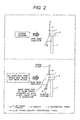
- the blade is turned (the pitch angle is changed) in a direction of smaller relative inflow angle (relative inflow angle of a wind flown into the blade, hereinafter simply referred to as an inflow angle).
- an inflow angle relative inflow angle of a wind flown into the blade
- the preferred aim of the present invention is to provide a windturbine and a method for stopping the windturbine that can reduce an unbalance in force possibly generated in an out-of-plane direction of a rotor of the windturbine in a process of stopping the windturbine to stop the windturbine in which some (for example, one) of blades is immobilized.
- the present invention may be configured as follows. When stopping a windturbine in which some (for example, one) of blades is immobilized, a pitch angle of a normal blade (blade that has not become immobilized) is changed in a direction of larger inflow angle to cause the blade to be in a state of feather (finally, a trailing edge of the blade locates at a windward).
- This description designates the control of the pitch angle that turns the blade or changes the pitch angle of the blade in the direction of larger inflow angle to place the blade in the state of feather and causes the trailing edge of the blade to locate at the windward as a negative feather.
- This description designates the usual feather operation, that is, the control of the pitch angle that turns the blade or changes the pitch angle in the direction of smaller inflow angle to place the blade in the state of feather through the state of the inflow angle being zero and causes the trailing edge of the blade to locate at the leeward as a positive feather.
- the present invention may be also configured as follows.
- the pitch angle of the blade or a state quantity having a correlation relationship with the pitch angle, such as a wind velocity
- the normal blade is set to be not a negative feather but a positive feather.
- the present invention is preferable to be a downwind windturbine.
- the present invention can reduce an unbalance in force possibly generated in the out-of-plane (rotor plane) direction of the windturbine in the process of stopping the windturbine.
- a large-size wind turbine generator (rated output: 100 kW or more) to which the present invention is applied basically performs an unpeopled, automatic operation.
- the large-size wind turbine generator connects to a power grid to which the generated electric power is supplied.
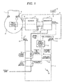
- the windturbine includes a plurality of blades 1, a hub 2, a main shaft 3, a gearbox 4, an electric generator 5, a nacelle 6, and a tower 7.
- the blade 1 is installed to the hub 2.
- the main shaft 3 is coupled to the hub 2.
- the gearbox 4 accelerates the rotation of the main shaft 3.
- the electric generator 5 is coupled to the gearbox 4 and generates electricity.
- the nacelle 6 rotatably supports the main shaft 3 and houses the gearbox 4 and the electric generator 5.
- the tower 7 rotatably supports the nacelle 6.
- the windturbine also includes a wind vane and anemometer 12, a rotation rate sensor 13, a yaw angle sensor 14, or a similar sensor.
- the rotation rate sensor 13 measures the rotation rate of the electric generator 5.
- the yaw angle sensor 14 measures the yaw angle of the nacelle 6. Outputs from these sensors are transmitted to a windturbine control panel 15 installed in the tower 7.
- the windturbine control panel 15 controls a controlled object in the windturbine based on a control command from the outside and the output from the respective sensors to perform the unpeopled, automatic operation of the windturbine.
- the controlled object is a pitch control device 9 (pitch drive mechanism 8), a yaw drive mechanism 10, an electric power control device 16, a main circuit breaker 17, an auxiliary machine group 19 (The auxiliary machine includes, for example, a rotor brake 11, a hydraulic pressure unit and a cooling unit, which are not illustrated.), and a similar device.
- the pitch control device 9 (pitch drive mechanism 8) changes the pitch angle of the blade 1.
- the yaw drive mechanism 10 changes the direction of the entire nacelle 6.
- the electric power control device 16 adjusts the electric power (or a rotating torque) of the windturbine.
- the main circuit breaker 17 plays a role in electrical coupling with the system.
- the windturbine monitors the state of the respective units by the respective sensors.
- the windturbine control panel 15 senses a failure or when a windturbine operator performs a manual operation (presses an emergency stop button 18 to perform a stop command on the windturbine control panel 15), the electric generation is aborted and the stop operation is performed.
- the present invention assumes the case where the blade has become immobilized (locked or stuck) as the failure.
- the present invention reverses the changing direction of the pitch angles of the normal blades (the turn direction of the normal blade for changing the pitch angle) while the windturbine stops, causing the blades to transition to the state of feather (negative feather).
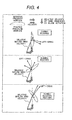
- Fig. 3 the following describes the fluid force acting on the blades during this negative feather.
- the fluid force acting on the blades during operation of the windturbine is similar to Fig. 2 .
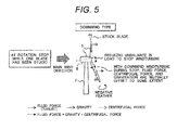
- the negative feather is performed.
- the negative feather is the following method. The changing of the pitch angle in the direction of larger inflow angle stalls the blade and reduces the lift as illustrated in "During negative feather" in Fig. 4 . Additionally, by increasing drag, the brake is applied while generating the fluid force in an out-of-plane direction to the leeward. Since the fluid force is generated in the out-of-plane direction to the leeward, at the blade on which the negative feather has been performed, the fluid force (thrust) faces the leeward as illustrated in Fig. 3 .
- the fluid force in the direction similar to the load to the leeward acting on the stuck blade is generated also on the normal blades, thus allowing stopping the windturbine. That is, the unbalance in force in the out-of-plane (rotor plane) direction while the windturbine stops can be reduced.
- the centrifugal force faces the out-of-plane direction reverse to the fluid force (thrust). Accordingly, these forces are mutually offset. Therefore, compared with the upwind windturbine, the downwind windturbine exhibits a smaller load acting on the blades, advantageous in the structural design of the blades. Additionally, the negative feather operation generates the load that bends the blade to the leeward. Meanwhile, in the case of the upwind windturbine, the blade is possibly in contact with the tower; therefore, a design of preventing the contact is required. By using the downwind windturbine, the leeward of the rotor is free from an obstacle. This is advantageous of preventing a problem of contact with the blade.
- the above-described control of the negative feather has the following problem.
- the following describes the problem with reference to "C Negative feather (over rated wind velocity)" in Fig. 7 . That is, the windturbine operates at the optimum pitch angle according to the wind velocity. However, in the case where the wind velocity exceeds the rated wind velocity of the windturbine, to keep an electric generation output constant, the pitch angle is changed to a feather side (side of smaller inflow angle) to reduce the fluid force. Thus, the operation is performed while releasing the wind. From this operating state of increasing the pitch angle, if the stop operation is performed by the negative feather, the fluid force temporarily increases (passes through a high center of lift) during the stop process, resulting in an increase in rotating torque. This phenomenon causes overspeeding in the stop operation of the windturbine.
- the inventors have found a solution to this problem as follows.
- the negative feather operation is performed on the shallow pitch angle.
- a positive feather operation is performed.
- the pitch angle is changed to the feather side (side of smaller inflow angle).
- the pitch angle is larger than the pitch angle when the wind velocity is equal to or less than the rated wind velocity. That is, at the wind velocity sufficiently higher than the rated wind velocity, as described above, the pitch angle is increased so as to release energy.
- the wind velocity changes by the position and also changes by the time. While it all depends, for example, the negative feather operation is performed at 0 to 7°, and the positive feather operation is performed at the excess of 7° depending on various conditions. In other words, near the rated wind velocity, the negative feather operation is performed. At the wind velocity sufficiently higher than the rated wind velocity (in the case where the problem of overspeeding becomes serious by performing the negative feather), the positive feather operation is performed.
- the pitch angle is controlled considering the wind velocity and the rotation rate of the windturbine. That is, it can be said that the wind velocity and the rotation rate of the windturbine are state quantities having a correlation relationship with the pitch angle. Accordingly, the controls of the negative feather and the positive feather can be used properly indexing the wind velocity and the rotation rate of the windturbine, instead of the pitch angle.
- Whether the blade has been stuck or not is, for example, determined by measuring the pitch angles of the respective blades and comparing the pitch angles with the command values of the respective pitch angles. Thus, whether the blade has been stuck or not is determined.
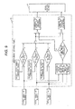
- Fig. 6 illustrates a control block diagram of this embodiment.
- This embodiment premises a windturbine having three blades. The pitch angles of the respective blades are measured and the pitch angles are compared with the command values of the respective pitch angles. Thus, whether the blade has been stuck or not is determined. If any of the blades has been stuck, the stop operation is performed on the windturbine. This stop operation of the windturbine is, as described above, performed by the negative feather.
- the windturbine control panel 15 outputs a stop command by the negative feather to the pitch control device 9.
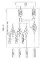
- Fig. 9 illustrates a control block diagram of this embodiment.
- This embodiment determines the proper use of the negative feather and the positive feather to stop the windturbine by whether the pitch angles of the blades exceed a predetermined threshold or not.
- the pitch angles serving as the index the average value, the maximum value, or the minimum value of the pitch angles of the respective blades can be used.
- a positive feather command is output.
- a negative feather command is output.
- Fig. 10 illustrates a control block diagram of this embodiment. This embodiment indexes the wind velocity for determining the proper use of the negative feather and the positive feather to stop the windturbine, instead of the average pitch angle.
- Fig. 11 illustrates a control block diagram of this embodiment.
- This embodiment indexes the rotation rate of the windturbine for determining the proper use of the negative feather and the positive feather to stop the windturbine, instead of the average pitch angle.
- the windturbine rotation rate different from the wind velocity, a correlation relationship with the pitch angle is possibly weak.
- the windturbine rotation rate can be utilized effectively as the index in a windturbine where the rotation rate becomes a rated rotation rate at the pitch angle of, for example, approximately 7°.
- the present invention is not limited to the above-described embodiments, and includes various modifications.
- the above-described embodiments are described in detail for simply describing the present invention, and do not necessarily include all the described configurations.
- a part of the configurations of one embodiment can be replaced by the configuration of another embodiment.
- a part of the configurations of one embodiment can be used with the addition of the configuration of another embodiment.
- another configuration can be added, deleted, or replaced.
Applications Claiming Priority (1)
| Application Number | Priority Date | Filing Date | Title |
|---|---|---|---|
| JP2014137392A JP6282187B2 (ja) | 2014-07-03 | 2014-07-03 | 風車及びその停止方法 |
Publications (1)
| Publication Number | Publication Date |
|---|---|
| EP2963286A1 true EP2963286A1 (de) | 2016-01-06 |
Family
ID=53496507
Family Applications (1)
| Application Number | Title | Priority Date | Filing Date |
|---|---|---|---|
| EP15174224.4A Withdrawn EP2963286A1 (de) | 2014-07-03 | 2015-06-29 | Windturbine und verfahren zum anhalten davon |
Country Status (3)
| Country | Link |
|---|---|
| EP (1) | EP2963286A1 (de) |
| JP (1) | JP6282187B2 (de) |
| TW (1) | TW201602455A (de) |
Cited By (3)
| Publication number | Priority date | Publication date | Assignee | Title |
|---|---|---|---|---|
| US20200025172A1 (en) * | 2018-07-17 | 2020-01-23 | General Electric Company | System and Method for Reducing Loads of a Wind Turbine When a Rotor Blade Becomes Stuck |
| WO2020029324A1 (zh) * | 2018-08-06 | 2020-02-13 | 大连理工大学 | 一种基于独立变桨的风电机组控制和制动方法 |
| US10975732B2 (en) | 2019-04-04 | 2021-04-13 | General Electric Company | Rotor turning device for balancing a wind turbine rotor |
Families Citing this family (2)
| Publication number | Priority date | Publication date | Assignee | Title |
|---|---|---|---|---|
| JP2019078223A (ja) * | 2017-10-25 | 2019-05-23 | 株式会社日本製鋼所 | 水平軸風車の制御装置、水平軸風車、水平軸風車の制御プログラム |
| CN113404639B (zh) * | 2021-08-05 | 2022-10-18 | 中国船舶重工集团海装风电股份有限公司 | 一种风电机组载荷友好型卡桨停机方法及系统 |
Citations (7)
| Publication number | Priority date | Publication date | Assignee | Title |
|---|---|---|---|---|
| JP2006336505A (ja) | 2005-05-31 | 2006-12-14 | Fuji Heavy Ind Ltd | 水平軸風車 |
| JP2007016628A (ja) | 2005-07-05 | 2007-01-25 | Fuji Heavy Ind Ltd | 水平軸風車 |
| JP2007064062A (ja) | 2005-08-30 | 2007-03-15 | Fuji Heavy Ind Ltd | 水平軸風車 |
| US20080290664A1 (en) * | 2005-07-26 | 2008-11-27 | Repower Systems Ag | Wind Power Plant Comprising Individual Pitch Devices |
| US20090047129A1 (en) * | 2005-05-31 | 2009-02-19 | Shigeo Yoshida | Horizontal axis wind turbine |
| US20090196752A1 (en) * | 2008-01-31 | 2009-08-06 | Gamesa Innovation & Technology, S.L. | Method for stopping a wind turbine |
| WO2013163795A1 (en) * | 2012-05-02 | 2013-11-07 | General Electric Company | System and method for stopping the operation of a wind turbine |
Family Cites Families (2)
| Publication number | Priority date | Publication date | Assignee | Title |
|---|---|---|---|---|
| JP2004011543A (ja) * | 2002-06-07 | 2004-01-15 | Fuji Heavy Ind Ltd | 水平軸型風車 |
| JP4468751B2 (ja) * | 2004-06-30 | 2010-05-26 | 富士重工業株式会社 | 水平軸風車およびその待機方法 |
-
2014
- 2014-07-03 JP JP2014137392A patent/JP6282187B2/ja active Active
-
2015
- 2015-06-29 EP EP15174224.4A patent/EP2963286A1/de not_active Withdrawn
- 2015-07-02 TW TW104121515A patent/TW201602455A/zh unknown
Patent Citations (7)
| Publication number | Priority date | Publication date | Assignee | Title |
|---|---|---|---|---|
| JP2006336505A (ja) | 2005-05-31 | 2006-12-14 | Fuji Heavy Ind Ltd | 水平軸風車 |
| US20090047129A1 (en) * | 2005-05-31 | 2009-02-19 | Shigeo Yoshida | Horizontal axis wind turbine |
| JP2007016628A (ja) | 2005-07-05 | 2007-01-25 | Fuji Heavy Ind Ltd | 水平軸風車 |
| US20080290664A1 (en) * | 2005-07-26 | 2008-11-27 | Repower Systems Ag | Wind Power Plant Comprising Individual Pitch Devices |
| JP2007064062A (ja) | 2005-08-30 | 2007-03-15 | Fuji Heavy Ind Ltd | 水平軸風車 |
| US20090196752A1 (en) * | 2008-01-31 | 2009-08-06 | Gamesa Innovation & Technology, S.L. | Method for stopping a wind turbine |
| WO2013163795A1 (en) * | 2012-05-02 | 2013-11-07 | General Electric Company | System and method for stopping the operation of a wind turbine |
Cited By (4)
| Publication number | Priority date | Publication date | Assignee | Title |
|---|---|---|---|---|
| US20200025172A1 (en) * | 2018-07-17 | 2020-01-23 | General Electric Company | System and Method for Reducing Loads of a Wind Turbine When a Rotor Blade Becomes Stuck |
| US10808680B2 (en) * | 2018-07-17 | 2020-10-20 | General Electric Company | System and method for reducing loads of a wind turbine when a rotor blade becomes stuck |
| WO2020029324A1 (zh) * | 2018-08-06 | 2020-02-13 | 大连理工大学 | 一种基于独立变桨的风电机组控制和制动方法 |
| US10975732B2 (en) | 2019-04-04 | 2021-04-13 | General Electric Company | Rotor turning device for balancing a wind turbine rotor |
Also Published As
| Publication number | Publication date |
|---|---|
| JP6282187B2 (ja) | 2018-02-21 |
| TW201602455A (zh) | 2016-01-16 |
| JP2016014362A (ja) | 2016-01-28 |
Similar Documents
| Publication | Publication Date | Title |
|---|---|---|
| US8529206B2 (en) | Wind turbine generator and yaw rotation control method for wind turbine generator | |
| EP2339743B1 (de) | Windstromerzeugungssystem und verfahren zu seiner steuerung | |
| JP4764422B2 (ja) | 風力タービンの制御および調節方法 | |
| US8334610B2 (en) | Gearless pitch control mechanism for starting, stopping and regulating the power output of wind turbines without the use of a brake | |
| EP2963286A1 (de) | Windturbine und verfahren zum anhalten davon | |
| US10337495B2 (en) | System and method for reducing vortex-induced tower vibrations of a wind turbine | |
| US20130088009A1 (en) | Method to Prevent Over Torque of Yaw Drive Components in a Wind Turbine | |
| US20090001724A1 (en) | Method and apparatus for controlling vertical axis wind power generation system | |
| CA2644019A1 (en) | Wind power generator system and control method of the same | |
| EP2844870B1 (de) | System und verfahren zum anhalten des betriebs einer windturbine | |
| US20120134807A1 (en) | Method for preventing rotor overspeed of a wind turbine | |
| EP2757251A1 (de) | Windturbine und Verfahren zu deren Betrieb | |
| EP2966297A1 (de) | Windenergieerzeugungssystem | |
| EP3470670B1 (de) | System und verfahren zum betreiben von windturbinen zur vermeidung von strömungsabrissen während der leistungsherabsetzung | |
| EP3913217B1 (de) | System und verfahren zur steuerung einer windturbine zum schutz der windturbine vor anormalem betrieb | |
| JP6227490B2 (ja) | ダウンウインド型風車及びその停止方法 | |
| US11608811B2 (en) | System and method for mitigating loads acting on a rotor blade of a wind turbine | |
| KR101363516B1 (ko) | 풍력 발전기용 발전기의 제어 방법 | |
| EP3812579A1 (de) | System und verfahren zur verbesserten extremlaststeuerung für windturbinenkomponenten | |
| US20090196752A1 (en) | Method for stopping a wind turbine | |
| WO2016138647A1 (en) | System and method for mitigating loads on a wind turbine | |
| KR102042259B1 (ko) | 풍력발전시스템 및 그것의 구동 정지 방법 | |
| KR101516546B1 (ko) | 풍력 발전기 및 그 제어방법 | |
| EP3957850A1 (de) | Windturbinenbetrieb bei extremen windbedingungen | |
| US11486356B2 (en) | System and method for controlling a wind turbine |
Legal Events
| Date | Code | Title | Description |
|---|---|---|---|
| PUAI | Public reference made under article 153(3) epc to a published international application that has entered the european phase |
Free format text: ORIGINAL CODE: 0009012 |
|
| 17P | Request for examination filed |
Effective date: 20150717 |
|
| AK | Designated contracting states |
Kind code of ref document: A1 Designated state(s): AL AT BE BG CH CY CZ DE DK EE ES FI FR GB GR HR HU IE IS IT LI LT LU LV MC MK MT NL NO PL PT RO RS SE SI SK SM TR |
|
| AX | Request for extension of the european patent |
Extension state: BA ME |
|
| 17Q | First examination report despatched |
Effective date: 20170206 |
|
| GRAP | Despatch of communication of intention to grant a patent |
Free format text: ORIGINAL CODE: EPIDOSNIGR1 |
|
| INTG | Intention to grant announced |
Effective date: 20190125 |
|
| STAA | Information on the status of an ep patent application or granted ep patent |
Free format text: STATUS: THE APPLICATION IS DEEMED TO BE WITHDRAWN |
|
| 18D | Application deemed to be withdrawn |
Effective date: 20190605 |