EP2757251A1 - Windturbine und Verfahren zu deren Betrieb - Google Patents
Windturbine und Verfahren zu deren Betrieb Download PDFInfo
- Publication number
- EP2757251A1 EP2757251A1 EP13382013.4A EP13382013A EP2757251A1 EP 2757251 A1 EP2757251 A1 EP 2757251A1 EP 13382013 A EP13382013 A EP 13382013A EP 2757251 A1 EP2757251 A1 EP 2757251A1
- Authority
- EP
- European Patent Office
- Prior art keywords
- wind
- speed
- pitch
- wind turbine
- rotor
- Prior art date
- Legal status (The legal status is an assumption and is not a legal conclusion. Google has not performed a legal analysis and makes no representation as to the accuracy of the status listed.)
- Withdrawn
Links
- 238000000034 method Methods 0.000 title claims abstract description 20
- 230000007246 mechanism Effects 0.000 claims abstract description 10
- 230000001052 transient effect Effects 0.000 claims description 10
- 238000005259 measurement Methods 0.000 claims description 7
- 230000007423 decrease Effects 0.000 description 14
- 230000000875 corresponding effect Effects 0.000 description 6
- 235000009413 Ratibida columnifera Nutrition 0.000 description 5
- 241000510442 Ratibida peduncularis Species 0.000 description 5
- 230000001419 dependent effect Effects 0.000 description 4
- 230000000694 effects Effects 0.000 description 4
- 230000008859 change Effects 0.000 description 3
- 230000004044 response Effects 0.000 description 2
- 238000000926 separation method Methods 0.000 description 2
- 230000006978 adaptation Effects 0.000 description 1
- 238000011217 control strategy Methods 0.000 description 1
- 230000002596 correlated effect Effects 0.000 description 1
- 230000005611 electricity Effects 0.000 description 1
- 238000012986 modification Methods 0.000 description 1
- 230000004048 modification Effects 0.000 description 1
- 230000002028 premature Effects 0.000 description 1
Images


Classifications
-
- F—MECHANICAL ENGINEERING; LIGHTING; HEATING; WEAPONS; BLASTING
- F03—MACHINES OR ENGINES FOR LIQUIDS; WIND, SPRING, OR WEIGHT MOTORS; PRODUCING MECHANICAL POWER OR A REACTIVE PROPULSIVE THRUST, NOT OTHERWISE PROVIDED FOR
- F03D—WIND MOTORS
- F03D7/00—Controlling wind motors
- F03D7/02—Controlling wind motors the wind motors having rotation axis substantially parallel to the air flow entering the rotor
- F03D7/022—Adjusting aerodynamic properties of the blades
- F03D7/0224—Adjusting blade pitch
-
- F—MECHANICAL ENGINEERING; LIGHTING; HEATING; WEAPONS; BLASTING
- F03—MACHINES OR ENGINES FOR LIQUIDS; WIND, SPRING, OR WEIGHT MOTORS; PRODUCING MECHANICAL POWER OR A REACTIVE PROPULSIVE THRUST, NOT OTHERWISE PROVIDED FOR
- F03D—WIND MOTORS
- F03D7/00—Controlling wind motors
- F03D7/02—Controlling wind motors the wind motors having rotation axis substantially parallel to the air flow entering the rotor
- F03D7/04—Automatic control; Regulation
- F03D7/042—Automatic control; Regulation by means of an electrical or electronic controller
-
- F—MECHANICAL ENGINEERING; LIGHTING; HEATING; WEAPONS; BLASTING
- F05—INDEXING SCHEMES RELATING TO ENGINES OR PUMPS IN VARIOUS SUBCLASSES OF CLASSES F01-F04
- F05B—INDEXING SCHEME RELATING TO WIND, SPRING, WEIGHT, INERTIA OR LIKE MOTORS, TO MACHINES OR ENGINES FOR LIQUIDS COVERED BY SUBCLASSES F03B, F03D AND F03G
- F05B2270/00—Control
- F05B2270/10—Purpose of the control system
- F05B2270/101—Purpose of the control system to control rotational speed (n)
- F05B2270/1011—Purpose of the control system to control rotational speed (n) to prevent overspeed
-
- F—MECHANICAL ENGINEERING; LIGHTING; HEATING; WEAPONS; BLASTING
- F05—INDEXING SCHEMES RELATING TO ENGINES OR PUMPS IN VARIOUS SUBCLASSES OF CLASSES F01-F04
- F05B—INDEXING SCHEME RELATING TO WIND, SPRING, WEIGHT, INERTIA OR LIKE MOTORS, TO MACHINES OR ENGINES FOR LIQUIDS COVERED BY SUBCLASSES F03B, F03D AND F03G
- F05B2270/00—Control
- F05B2270/30—Control parameters, e.g. input parameters
- F05B2270/32—Wind speeds
-
- F—MECHANICAL ENGINEERING; LIGHTING; HEATING; WEAPONS; BLASTING
- F05—INDEXING SCHEMES RELATING TO ENGINES OR PUMPS IN VARIOUS SUBCLASSES OF CLASSES F01-F04
- F05B—INDEXING SCHEME RELATING TO WIND, SPRING, WEIGHT, INERTIA OR LIKE MOTORS, TO MACHINES OR ENGINES FOR LIQUIDS COVERED BY SUBCLASSES F03B, F03D AND F03G
- F05B2270/00—Control
- F05B2270/30—Control parameters, e.g. input parameters
- F05B2270/322—Control parameters, e.g. input parameters the detection or prediction of a wind gust
-
- Y—GENERAL TAGGING OF NEW TECHNOLOGICAL DEVELOPMENTS; GENERAL TAGGING OF CROSS-SECTIONAL TECHNOLOGIES SPANNING OVER SEVERAL SECTIONS OF THE IPC; TECHNICAL SUBJECTS COVERED BY FORMER USPC CROSS-REFERENCE ART COLLECTIONS [XRACs] AND DIGESTS
- Y02—TECHNOLOGIES OR APPLICATIONS FOR MITIGATION OR ADAPTATION AGAINST CLIMATE CHANGE
- Y02E—REDUCTION OF GREENHOUSE GAS [GHG] EMISSIONS, RELATED TO ENERGY GENERATION, TRANSMISSION OR DISTRIBUTION
- Y02E10/00—Energy generation through renewable energy sources
- Y02E10/70—Wind energy
- Y02E10/72—Wind turbines with rotation axis in wind direction
Definitions
- Wind turbines are commonly used to supply electricity into the electrical grid.
- Wind turbines of this kind generally comprise a rotor with a rotor hub and a plurality of blades.
- the rotor is set into rotation under the influence of the wind on the blades.
- the rotation of the rotor shaft either directly drives the generator rotor ("directly driven") or through the use of a gearbox.
- a variable speed wind turbine may typically be controlled by varying the generator torque and the pitch angle of the blades. As a result, aerodynamic torque, rotor speed and electrical power will vary.
- FIG. 1 A common prior art control strategy of a variable speed wind turbine is described with reference to figure 1 .
- the operation of a typical variable speed wind turbine is illustrated in terms of the pitch angle ( ⁇ ), the electrical power generated (P), the generator torque (M) and the rotational velocity of the rotor ( ⁇ ), as a function of the wind speed.
- the rotor In a first operational range, from the cut-in wind speed to a first wind speed (e.g. approximately 5 or 6 m/s), the rotor may be controlled to rotate at a substantially constant speed that is just high enough to be able to accurately control it.
- the cut-in wind speed may be e.g. approximately 3 m/s.
- the objective is generally to maximize power output while maintaining the pitch angle of the blades constant so as to capture maximum energy.
- the generator torque and rotor speed may be varied so as keep the tip speed ratio ⁇ (tangential velocity of the tip of the rotor blades divided by the prevailing wind speed) constant so as to maximize the power coefficient C p .
- the generator speed substantially equals the rotor speed.
- a substantially constant ratio exists between the rotor speed and the generator speed.
- this third operational range which starts at reaching nominal rotor rotational speed and extends until reaching nominal power, the rotor speed may be kept constant, and the generator torque may be varied to such effect.
- this third operational range extends substantially from the second wind speed to the nominal wind speed e.g. from approximately 8.5 m/s to approximately 11 m/s.
- a fourth operational range which may extend from the nominal wind speed to the cut-out wind speed (for example from approximately 11 m/s to 25 m/s)
- the blades may be rotated ("pitched") to maintain the aerodynamic torque delivered by the rotor substantially constant.
- the pitch may be actuated such as to maintain the rotor speed substantially constant.
- the wind turbine's operation is interrupted.
- the blades are normally kept in a constant pitch position, namely the "below rated pitch position".
- Said default pitch position may generally be close to a 0° pitch angle. The exact pitch angle in "below rated” conditions however depends on the complete design of the wind turbine.
- the before described operation may be translated into a so-called power curve, such as the one shown in figure 1 .
- a power curve may reflect the optimum operation of the wind turbine under steady-state conditions.
- the operation may not necessarily be optimum.
- FIG 2a a profile of a wind turbine blade is depicted in operation.
- the forces generated by the aerodynamic profile are determined by the wind that the profile "experiences", the effective wind speed V e .
- the effective wind speed is composed of the axial free stream wind speed V a and the tangential speed of the profile V t .
- the axial free stream wind speed may e.g. be equal to approximately two thirds of the wind speed V w .
- a blade may theoretically be divided in an infinite number of blade sections, each blade section having its own local radius and its own local aerodynamic profile. For any given rotor speed, the tangential speed of each blade section will depend on its distance to the rotational axis of the hub (herein referred to as local radius).
- the contribution to lift and drag of each blade section may be summed to arrive at the total drag and lift generated by the blade.
- Both the drag coefficient C D and the lift coefficient C L depend on the profile or the blade section and vary as a function of the angle of attack of the blade section.
- the angle of attack ⁇ may be defined as the angle between the chord line of a profile (or blade section) and the vector of the effective wind flow, see also figure 2a .
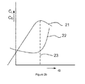
- Figure 2b illustrates in a very general manner how the lift coefficient and drag coefficient may vary as a function of the angle of attack of a blade section.
- the lift coefficient (reference sign 21) increases to a certain maximum at a so-called critical angle of attack 23. This critical angle of attack is also sometimes referred to as stall angle.
- the drag coefficient (reference sign 22) may generally be quite low and starts increasing in an important manner close to the critical angle of attack 23.
- This rapid change in aerodynamic behaviour of a profile or blade section is linked generally to the phenomenon that the aerodynamic flow around the profile (or blade section) is not able to follow the aerodynamic contour and the flow separates from the profile. The separation causes a wake of turbulent flow, which reduces the lift of a profile and increases the drag significantly.
- the pitch angle may be defined as the angle between the rotor plane and the chord line of a profile. Integrating the tangential force distribution over the radius provides the driving torque.
- the angle of attack of any blade section is preferably kept below the critical angle of attack such that lift may be higher and drag may be lower.
- each blade section depends on the tangential speed of the specific rotor blade section, the wind speed, the pitch angle and the local twist angle of the blade section.
- the local twist angle of a blade section may generally be considered constant, unless some kind of deformable blade is used.
- the tangential speed of the rotor blade section depends on the rotor speed (angular velocity of the rotor which is obviously the same for the whole blade and thus for each blade section) and on the distance of the blade section to the rotational axis.
- the torque generated may be correlated to one of the lines of figure 2d of constant pitch angle.
- These lines depict the power coefficient (C p ), i.e. the ratio between the mechanical power captured by the wind turbine rotor and the available power in the wind, as a function of tip speed ratio ⁇ and for different pitch angles. They may be obtained as cross-sections of planes of constant pitch angle with a figure such as the one shown in figure 2c .
- C p curves provide information about the torque dependence on pitch angle. For each pitch angle, there is a certain critical tip speed ratio. Below this tip speed ratio, stall may occur, i.e. the angle of attack is higher than the previously mentioned critical angle of attack.
- this operational range may extend from the nominal wind speed to the cut-out wind speed.
- a nacelle mounted anemometer will generally, due its location on top of the nacelle and behind the rotor, not measure the wind speed very accurately and its measurements may show a wind speed that largely varies with a high frequency. If the pitch system were to actuate on these measurements, it would constantly adjust the blade pitch (which would lead to premature wear of the pitch system) and the pitch system would not even be able to follow the commands that vary constantly. And if one also takes into account effects such as wind shear and wind veer, which cannot even be registered with a nacelle mounted anemometer, it becomes clear that the anemometer cannot be used for deriving pitch signals.
- the rotor speed is used instead of using measurements from an anemometer.
- the rotor speed may be measured e.g. by measuring the generator rotor speed.
- the rotor speed will correspond to the generator rotor speed, and in wind turbines employing a gearbox, there will generally be a fixed ratio between generator rotor speed and rotor speed.
- the pitch system is then actuated in such a manner as to keep the rotor speed constant. This may work well in steady-state conditions or almost steady-state conditions, but in conditions which change relatively quickly, this may lead to undesirable results. This may be illustrated further with reference to figure 2e .
- the pitch angle will generally not be close to the critical pitch angle, wherein the critical pitch angle if the pitch angle corresponding for this particular situation to a critical angle of attack.
- the pitch angle will be higher than the critical angle, as the pitch of the blades is used to reduce the loads on the rotor and maintain aerodynamic torque substantially constant.
- the pitch angle should be increased. Nevertheless, as the pitch system depends on the rotor inertia, it cannot track a sudden wind change, so blade pitch remains somewhat stuck, thus resulting in a large angle of attack. Depending on the precise effects of the wind, and the inertia of the rotor, it may be that the rotor speed even decreases a little bit, due to the separation of the flow from the blades. In response to this decrease in rotor speed, the pitch system will reduce the pitch angle more, thus aggravating the situation by further increasing the angle of attack.
- Mexican hat wind gusts are defined in the IEC 64100-1 2nd edition 1999-02 standard, since they may be particularly dangerous wind gusts. This standard defines Mexican hat wind gusts at various speeds, and at various azimuth angles.
- the loads a wind turbine suffers during such a wind gust are severe and may define design loads for the wind turbine. This is due to the decrease in wind speed, before the high increase in wind speed (see figure 1 ).
- the pitch system tries to adapt the blades to this decrease (the blades are initially rotated in such a way to increase the aerodynamic torque by increasing their angle of attack, i.e. the pitch rate is below zero).
- the pitch adaptation still ongoing, a significant increase in wind speed occurs.
- the aerodynamic torque and the thrust force on the hub can thus be very high.
- the pitch of the wind turbine will then start to adapt to these new wind conditions.
- a typical pitch system may have an inherent pitch limitation of approximately 5° / second. Such a pitch rate may in principle be fast enough to respond to wind variations occurring during operation of the wind turbine.
- the limiting factor may not be the pitch drive system but the means used to sense wind speed, i.e. rotor speed.
- a method of operating a variable speed wind turbine as a function of a wind speed is provided.
- the wind turbine has a rotor with a plurality of blades, and one or more pitch mechanisms for rotating the blades.
- the method comprises a sub-nominal zone of operation for wind speeds below the nominal wind speed and a supra-nominal zone of operation for wind speeds above the nominal wind speed.
- the blades are pitched so as to maintain the rotor speed substantially constant, and a tip speed ratio of the wind turbine is substantially continuously being determined and wherein an instantaneous minimum pitch angle is substantially continuously being determined based on the instantaneous tip speed ratio, and the blades are never pitched below the minimum pitch angle.
- the wind turbine can follow normal operation for (substantially) steady-state conditions.
- the problem of stalling of the blades in case of transients can be avoided; the tip speed ratio is monitored substantially continuously (i.e. with a frequency high enough to adapt for wind changes).
- the frequency of determining the tip speed ratio may e.g. be every 0,5 seconds, every second, or every few seconds.
- the minimum pitch angle that should not be surpassed is known. Using this information, this minimum pitch angle is set as a boundary condition for normal operation, or at least in the supra-nominal zone of operation. In the supra-nominal zone of operation, the actual pitch angle will normally be significantly higher than this minimum pitch angle and normal operation will thus not be affected. Only in case of transients, the added boundary condition helps the wind turbine to operate better.
- the minimum pitch angle is defined as the pitch angle corresponding to a critical angle of attack of a wind turbine blade section.
- the critical angle of attack of a wind turbine blade section is the angle of attack at which the wind turbine blade section starts to stall.
- the precise angle of attack for any section of a blade may be different, as it depends on local twist angle and the distance of the section to the rotational axis, as well as on the wind speed and pitch angle, the last two factors being common for the whole blade, but the first two varying along the blade.
- the minimum pitch angle may be defined as the pitch angle corresponding to an angle of attack that is a predefined amount or percentage below a critical angle of attack of a wind turbine blade section. This predefined amount or percentage may be regarded as a security measure.
- the representative wind turbine blade section may be chosen as the section at 25% of the blade length.
- a wind turbine having a generator, a rotor with a plurality of blades, one or more pitch mechanisms for rotating the blades, a system for determining the rotor speed, a wind speed sensor, and a control system comprising a pitch control system and a generator control system.
- the generator control system is adapted to control the generator and the pitch control system is adapted to control the pitch mechanisms.
- the generator control system is adapted to determine generator torque commands in accordance with a steady-state control loop and the pitch control system is adapted to determine pitch commands in accordance with a transient control loop and the steady-state control loop.
- the steady-state control loop is adapted to calculate generator torque set commands and pitch set commands based at least partially on the instantaneous rotor speed determined by the system for determining the rotor speed.
- the transient control loop is adapted to calculate an instantaneous tip speed ratio based on a wind speed measured by the wind speed sensor and the instantaneous rotor speed determined by the system for determining the rotor speed, and is further adapted to determine instantaneous minimum pitch commands based on the instantaneous tip speed ratio.
- the pitch control system In a supra-nominal zone of operation for wind speeds above a nominal wind speed, the pitch control system is adapted to determine whether the pitch set command is above the instantaneous minimum pitch command, and in case of positive result, follow the received pitch set command. In case of negative result, the pitch control system is adapted to follow the instantaneous minimum pitch command.
- a wind turbine is provided with a control system that may be adapted to follow a predefined power curve.
- the wind turbine may thus be adapted to varying wind speeds by adjusting a pitch angle of the blades in order to maintain rotor speed (or generator speed) constant.
- rotor speed or generator speed
- an instantaneous minimum pitch angle is monitored constantly and the control system ensures that this minimum pitch angle is superposed as a minimum boundary on the normal pitch control. Aerodynamic stall of the rotor blades may thus be avoided.
- Figure 3 illustrates a wind turbine 40 having a rotor with three blades 41, 42 and 43.
- a nacelle 45 is mounted on wind turbine tower 44.
- An anemometer 46 is mounted on the nacelle 45. The anemometer 46 may be used to measure wind speed, however because of its location on the nacelle, behind the rotor, the wind speed measured by the anemometer may vary a lot and in general may not be very reliable.
- the wind turbine may have one or more pitch systems to rotate the blades 41, 42, 43 collectively or individually.
- Figure 1 represents a typical power curve for a variable speed wind turbine with pitch capability.
- the generator torque and rotor speed may be maintained constant even though the wind speed increases. This can be achieved by pitching the wind turbine blades, i.e. by rotating the blades along their longitudinal axes and with respect to the hub; by increasing the pitch of the blades, their angle of attack decreases and their contribution to the torque also decreases.
- the ideal power curve as depicted in figure 1 may most reliably be followed during steady-state conditions if the pitch system(s) is/are directly controlled by a sensor indicating the rotor speed.
- the rotational speed of the rotor may be measured directly or may be determined by measuring the rotational speed of the generator rotor.
- the pitch system is thus actuated to keep the speed constant, and if generator torque is maintained constant as well, this means that aerodynamic torque is maintained substantially constant as well.
- a particularly challenging situation may be a Mexican hat wind gust in the supra-nominal zone of operation.
- examples of the present invention may equally well be suitable in different transient conditions, such as sudden increases or decreases of wind speeds, for example in case of increased turbulence.
- the wind speed first decreases. Although the rotor may be slow to react, the rotor speed may diminish a little bit.
- the reaction of the pitch system may thus be to increase the angle of attack of the blades (i.e. decrease the pitch) so that the blades capture the wind "better", i.e. increase their lift.
- a consequence of the stall may be relatively high loads.
- Another consequence may be a decrease in rotor speed.
- the reaction of the pitch system may be to further decrease the pitch (and increase the angle of attack), thus aggravating the stall.
- the tip speed ratio may be determined in a substantially continuous manner by measuring both wind speed and (generator) rotor speed. Given the real-time tip speed ratio, a minimum pitch angle may be determined which corresponds to a maximum angle of attack of the blade which should not be surpassed. This maximum angle of attack of the blade may correspond substantially to a critical angle of attack. Alternatively, it may correspond to an angle of attack with a predefined distance to the critical angle of attack.
- the anemometer when the wind speed starts to increase, the anemometer will be able to measure the increase in wind speed before the rotor speed increases.
- the input for the pitch system normally is the rotor speed
- a boundary condition is set for the pitch angle not to surpass a minimum pitch angle as determined based on the anemometer (or LIDAR or other wind measuring device).
- the point of operation moves from point A to point C (instead of to point B), which is located to the right of ⁇ crit,2 , that is, to the right of the pitch angle that would lead to stalling of the blade.
- the blades will thus not stall and operation may continue in a more efficient manner, with lower blade loads.
- tower loads are also reduced as situations with high wind and low speed are avoided. These situations result in high thrust on the wind turbine rotor which would lead to abnormally high loads on the tower as well.
- the same effect can be also explained with reference to figure 4b .
- the curve indicated with "normal” illustrates the blade pitch angle as a function of the tip speed ratio under steady-state conditions as may be determined in accordance with a power curve such as the one illustrated in figure 1 .
- This problem may be avoided, according to the present invention, by using a second blade pitch setpoint that defines a minimum boundary. This value is not dependent on the rotor speed but on the tip speed ratio.
- the curve labelled "critical”, defining ⁇ crit values for each tip speed ratio may be used as this minimum boundary. The resulting operational point would thus be point C 2 .
- a curve defining minimum pitch angle values which lie slightly above the critical pitch angles may be used as such a minimum boundary.
- a curve defining minimum pitch angle values which lie slightly above the critical pitch angles may be used as such a minimum boundary.
- such a curve is labelled with "minimum”.
- the resulting operating point may thus be point C 1 .
- the minimum pitch values may in some embodiments be e.g. the pitch angle corresponding to an angle of attack that is a predefined amount or percentage below a critical angle of attack of a representative wind turbine blade section for the supra-nominal zone of operation.
- FIG. 5 illustrates a wind turbine and a control system according to an example of the present invention.
- Wind turbine 40 comprises a generator and one or more pitch actuators 65.
- the pitch actuators or pitch mechanisms may be controlled by a pitch control system 60.
- the pitch control system 60 may send pitch commands 61 to the pitch actuators 65.
- a result is the setting of pitch angle 66 in the wind turbine 40.
- a generator control system 50 may send torque commands to a generator 55 and a converter 53 related to the generator. A result is the setting of the generator torque 56 in the wind turbine 40.
- Results of both settings in the wind turbine include a generator speed, ⁇ gen , and electrical power P generated.
- a control system of the wind turbine may comprise a steady state control loop 70 and a transient control loop 80.
- the steady state control loop 70 may be adapted generally to control the wind turbine in such a way that a predefined power curve, e.g. such as the one in figure 1 is followed.
- the transient control loop may be adapted to ensure that the instantaneous pitch angles of the blades do not sink below a minimum pitch angle. This minimum pitch angle may be e.g. a critical pitch angle for a representative portion of the blade, e.g. at 25% of the blade length.
- the steady state control loop 70, a generator speed sensor 36 may measure the generator speed, ⁇ meas .
- a comparison of the measured generator speed, ⁇ meas , with an expected generator speed ⁇ steady gives an error result ⁇ .
- the torque controller 50 and the pitch controller 60 can determine pitch commands 61 and generator torque commands 51.
- the generator torque or the pitch angle of the blades, or both may be adapted to generally follow the predefined power curve.
- the transient control loop 80 comprises a tip speed ratio calculator TSR.
- the calculation of an instantaneous tip speed ratio may be based on a wind speed V wind as measured by a nacelle mounted anemometer 46.
- the measurement from the anemometer upon which the determination of the minimum pitch angle is based may be an average wind speed as measured by the anemometer over a period of e.g. 1-5 seconds, e.g. 3 seconds.
- any other system for determining a representative wind speed can be used, such as e.g. a LIDAR.
- the calculation of the instantaneous tip speed ratio may be based on the measured generator speed, ⁇ meas .
- the rotor speed used in the calculation may be the measured generator speed in the case of direct drive wind turbines, or may have a constant ratio with the generator speed in the case of wind turbines with a gearbox.
- the calculated instantaneous tip speed ratio, ⁇ may be sent to a minimum pitch commander 69.
- the minimum pitch commander may send instantaneous minimum pitch commands ⁇ min to the pitch controller 60.
- the pitch command 61 sent to the pitch mechanism(s) may be the pitch set command determined in the steady state control loop if it is above the minimum pitch command. If the pitch set command of the steady state control loop is below the instantaneous minimum pitch command the instantaneous minimum pitch command (as determined in the steady state control loop) is followed and sent to the pitch mechanism(s).
- the steady state control loop may send constant generator torque commands to the converter 53 and generator 55 and varying pitch commands 61 to the pitch actuator(s) 65.
- the pitch commands are varied so as to maintain the generator speed constant.
- the transient control loop 80 ensures that the pitch angle does not fall below a minimum pitch angle, so that the blade does not stall.
Landscapes
- Engineering & Computer Science (AREA)
- Life Sciences & Earth Sciences (AREA)
- Sustainable Development (AREA)
- Sustainable Energy (AREA)
- Chemical & Material Sciences (AREA)
- Combustion & Propulsion (AREA)
- Mechanical Engineering (AREA)
- General Engineering & Computer Science (AREA)
- Physics & Mathematics (AREA)
- Fluid Mechanics (AREA)
- Wind Motors (AREA)
Priority Applications (4)
| Application Number | Priority Date | Filing Date | Title |
|---|---|---|---|
| EP13382013.4A EP2757251A1 (de) | 2013-01-17 | 2013-01-17 | Windturbine und Verfahren zu deren Betrieb |
| US14/760,687 US10161383B2 (en) | 2013-01-17 | 2014-01-17 | Methods of operating a wind turbine |
| PCT/EP2014/050903 WO2014111522A1 (en) | 2013-01-17 | 2014-01-17 | Methods of operating a wind turbine |
| US16/225,434 US10669987B2 (en) | 2013-01-17 | 2018-12-19 | Methods of operating a wind turbine |
Applications Claiming Priority (1)
| Application Number | Priority Date | Filing Date | Title |
|---|---|---|---|
| EP13382013.4A EP2757251A1 (de) | 2013-01-17 | 2013-01-17 | Windturbine und Verfahren zu deren Betrieb |
Publications (1)
| Publication Number | Publication Date |
|---|---|
| EP2757251A1 true EP2757251A1 (de) | 2014-07-23 |
Family
ID=47623995
Family Applications (1)
| Application Number | Title | Priority Date | Filing Date |
|---|---|---|---|
| EP13382013.4A Withdrawn EP2757251A1 (de) | 2013-01-17 | 2013-01-17 | Windturbine und Verfahren zu deren Betrieb |
Country Status (3)
| Country | Link |
|---|---|
| US (2) | US10161383B2 (de) |
| EP (1) | EP2757251A1 (de) |
| WO (1) | WO2014111522A1 (de) |
Cited By (9)
| Publication number | Priority date | Publication date | Assignee | Title |
|---|---|---|---|---|
| WO2017102570A1 (de) * | 2015-12-17 | 2017-06-22 | Wobben Properties Gmbh | Verfahren zum steuern einer windenergieanlage |
| CN110761945A (zh) * | 2018-07-27 | 2020-02-07 | 北京金风科创风电设备有限公司 | 风力发电机组的叶片失速控制方法及装置 |
| US10677218B2 (en) | 2015-11-19 | 2020-06-09 | Vestas Wind Systems A/S | Control of a wind turbine during recovery after a grid fault |
| CN111601968A (zh) * | 2018-01-15 | 2020-08-28 | 乌本产权有限公司 | 用于控制风能设施的方法和风能设施 |
| CN111828246A (zh) * | 2019-04-23 | 2020-10-27 | 新疆金风科技股份有限公司 | 风力发电机组防过速控制方法和装置、存储介质 |
| CN112055782A (zh) * | 2018-05-03 | 2020-12-08 | 通用电气公司 | 用于控制风力涡轮转子叶片的桨距角的系统和方法 |
| CN112112759A (zh) * | 2019-06-19 | 2020-12-22 | 乌本产权有限公司 | 风力涡轮机、操作其的方法、风力涡轮机的布置及风电场 |
| CN114026322A (zh) * | 2019-06-27 | 2022-02-08 | 乌本产权有限公司 | 用于风能设施的转子,风能设施和相关的方法 |
| CN114303012A (zh) * | 2019-06-27 | 2022-04-08 | 维斯塔斯风力系统集团公司 | 低于额定风速时控制风力涡轮机的功率输出 |
Families Citing this family (7)
| Publication number | Priority date | Publication date | Assignee | Title |
|---|---|---|---|---|
| US10669986B2 (en) * | 2014-09-01 | 2020-06-02 | Vestas Wind Systems A/S | Relating to the determination of rotor imbalances in a wind turbine |
| ES2563092B1 (es) * | 2014-09-10 | 2016-12-19 | Acciona Windpower, S.A. | Método de control de un aerogenerador |
| WO2016078668A1 (en) | 2014-11-21 | 2016-05-26 | Vestas Wind Systems A/S | A method for estimating a wind speed in a stable manner |
| CN104879273A (zh) * | 2015-06-12 | 2015-09-02 | 浙江运达风电股份有限公司 | 一种提高风力发电机组风能捕获的控制方法 |
| DE102018113531A1 (de) * | 2018-06-06 | 2019-12-12 | Wobben Properties Gmbh | Verfahren zum Betreiben einer Windenergieanlage sowie Einrichtung zum Steuern und/oder Regeln einer Windenergieanlage und Windenergieanlage mit einem Rotor und einem über den Rotor angetriebenen Generator |
| DE102018129622A1 (de) * | 2018-11-23 | 2020-05-28 | Wobben Properties Gmbh | Reglerstruktur und Regelverfahren für eine Windenergieanlage |
| US10927812B2 (en) * | 2019-02-19 | 2021-02-23 | General Electric Company | Method of dynamically adjusting a rate of change of a rotor speed set point during wind turbine shutdown |
Citations (4)
| Publication number | Priority date | Publication date | Assignee | Title |
|---|---|---|---|---|
| EP1612414A2 (de) * | 2004-06-30 | 2006-01-04 | General Electric Company | Verfahren sowie Vorrichtung zur Reduktion der Rotorbelastungen einer Windenergieanlage |
| US20070057517A1 (en) * | 2005-09-09 | 2007-03-15 | Mcnerney Gerald | Wind turbine load control method |
| EP2177754A2 (de) * | 2008-10-16 | 2010-04-21 | General Electric Company | Blattwinkelverwaltungsverfahren und Verwaltungssystem. |
| EP2481916A1 (de) * | 2011-01-26 | 2012-08-01 | Chapdrive As | Windradstromerzeugungssystem mit Hydraulikgetriebe |
Family Cites Families (4)
| Publication number | Priority date | Publication date | Assignee | Title |
|---|---|---|---|---|
| DE19731918B4 (de) * | 1997-07-25 | 2005-12-22 | Wobben, Aloys, Dipl.-Ing. | Windenergieanlage |
| DK2719895T3 (en) * | 2012-10-09 | 2017-10-30 | Ge Renewable Tech | Method for monitoring a wind turbine |
| EP2757253B1 (de) * | 2013-01-17 | 2019-04-10 | GE Renewable Technologies Wind B.V. | Verfahren zum Starten einer Windturbine |
| DK2878809T3 (en) * | 2013-11-29 | 2017-09-25 | Alstom Renovables Espana Sl | Methods of operating a wind turbine, wind turbines and wind farms |
-
2013
- 2013-01-17 EP EP13382013.4A patent/EP2757251A1/de not_active Withdrawn
-
2014
- 2014-01-17 WO PCT/EP2014/050903 patent/WO2014111522A1/en active Application Filing
- 2014-01-17 US US14/760,687 patent/US10161383B2/en active Active
-
2018
- 2018-12-19 US US16/225,434 patent/US10669987B2/en active Active
Patent Citations (4)
| Publication number | Priority date | Publication date | Assignee | Title |
|---|---|---|---|---|
| EP1612414A2 (de) * | 2004-06-30 | 2006-01-04 | General Electric Company | Verfahren sowie Vorrichtung zur Reduktion der Rotorbelastungen einer Windenergieanlage |
| US20070057517A1 (en) * | 2005-09-09 | 2007-03-15 | Mcnerney Gerald | Wind turbine load control method |
| EP2177754A2 (de) * | 2008-10-16 | 2010-04-21 | General Electric Company | Blattwinkelverwaltungsverfahren und Verwaltungssystem. |
| EP2481916A1 (de) * | 2011-01-26 | 2012-08-01 | Chapdrive As | Windradstromerzeugungssystem mit Hydraulikgetriebe |
Cited By (20)
| Publication number | Priority date | Publication date | Assignee | Title |
|---|---|---|---|---|
| US10677218B2 (en) | 2015-11-19 | 2020-06-09 | Vestas Wind Systems A/S | Control of a wind turbine during recovery after a grid fault |
| WO2017102570A1 (de) * | 2015-12-17 | 2017-06-22 | Wobben Properties Gmbh | Verfahren zum steuern einer windenergieanlage |
| KR20180095020A (ko) * | 2015-12-17 | 2018-08-24 | 보벤 프로퍼티즈 게엠베하 | 풍력 발전 설비의 제어 방법 |
| CN108474345A (zh) * | 2015-12-17 | 2018-08-31 | 乌本产权有限公司 | 用于控制风能设备的方法 |
| KR102091135B1 (ko) | 2015-12-17 | 2020-03-19 | 보벤 프로퍼티즈 게엠베하 | 풍력 발전 설비의 제어 방법 |
| CN108474345B (zh) * | 2015-12-17 | 2020-09-11 | 乌本产权有限公司 | 用于控制风能设备的方法 |
| US10995731B2 (en) | 2015-12-17 | 2021-05-04 | Wobben Properties Gmbh | Method for controlling a wind turbine |
| CN111601968B (zh) * | 2018-01-15 | 2023-09-19 | 乌本产权有限公司 | 用于控制风能设施的方法和风能设施 |
| CN111601968A (zh) * | 2018-01-15 | 2020-08-28 | 乌本产权有限公司 | 用于控制风能设施的方法和风能设施 |
| CN112055782A (zh) * | 2018-05-03 | 2020-12-08 | 通用电气公司 | 用于控制风力涡轮转子叶片的桨距角的系统和方法 |
| EP3788257A4 (de) * | 2018-05-03 | 2021-11-24 | General Electric Company | System und verfahren zur steuerung des anstellwinkels eines windturbinenrotorblatts |
| CN112055782B (zh) * | 2018-05-03 | 2023-10-31 | 通用电气公司 | 用于控制风力涡轮转子叶片的桨距角的系统和方法 |
| CN110761945B (zh) * | 2018-07-27 | 2020-11-03 | 北京金风科创风电设备有限公司 | 风力发电机组的叶片失速控制方法及装置 |
| CN110761945A (zh) * | 2018-07-27 | 2020-02-07 | 北京金风科创风电设备有限公司 | 风力发电机组的叶片失速控制方法及装置 |
| CN111828246A (zh) * | 2019-04-23 | 2020-10-27 | 新疆金风科技股份有限公司 | 风力发电机组防过速控制方法和装置、存储介质 |
| CN112112759A (zh) * | 2019-06-19 | 2020-12-22 | 乌本产权有限公司 | 风力涡轮机、操作其的方法、风力涡轮机的布置及风电场 |
| CN114026322A (zh) * | 2019-06-27 | 2022-02-08 | 乌本产权有限公司 | 用于风能设施的转子,风能设施和相关的方法 |
| CN114303012A (zh) * | 2019-06-27 | 2022-04-08 | 维斯塔斯风力系统集团公司 | 低于额定风速时控制风力涡轮机的功率输出 |
| EP3990777B1 (de) | 2019-06-27 | 2023-06-07 | Vestas Wind Systems A/S | Steuerung der leistungsabgabe einer windturbine mit verminderter windgeschwindigkeit |
| US12006914B2 (en) | 2019-06-27 | 2024-06-11 | Vestas Wind Systems A/S | Controlling power output of a wind turbine at below-rated wind speed |
Also Published As
| Publication number | Publication date |
|---|---|
| US20150354535A1 (en) | 2015-12-10 |
| WO2014111522A1 (en) | 2014-07-24 |
| US10161383B2 (en) | 2018-12-25 |
| US10669987B2 (en) | 2020-06-02 |
| US20190264653A1 (en) | 2019-08-29 |
Similar Documents
| Publication | Publication Date | Title |
|---|---|---|
| US10669987B2 (en) | Methods of operating a wind turbine | |
| US7898100B2 (en) | Method of operating a wind turbine with pitch control, a wind turbine and a cluster of wind turbine | |
| EP3343027B1 (de) | Verfahren zur reduzierung von lasten, die auf ein windturbinengierungssystem wirken | |
| EP2556249B1 (de) | Windturbine | |
| EP2757252B1 (de) | Verfahren zum Betrieb einer Windturbine | |
| EP3607198B1 (de) | Luftdichteabhängiger turbinenbetrieb | |
| US10662924B2 (en) | Rotor blade control for high winds | |
| EP2556248B1 (de) | Windturbine | |
| US10215159B2 (en) | Method of starting a wind turbine | |
| US9127644B2 (en) | Wind turbine and an associated control method | |
| WO2011157271A2 (en) | A method and control unit for controlling a wind turbine in dependence on loading experienced by the wind turbine | |
| EP2719893B1 (de) | Verfahren zum Betrieb einer drehzahlvariablen Windturbine | |
| WO2015048972A1 (en) | Safe mode operation at high yaw error | |
| EP2634419B1 (de) | Verfahren zum Betrieb einer Windturbine | |
| US12092085B2 (en) | Method for detecting an accretion of ice on a wind turbine | |
| TW201602455A (zh) | 風車及其停止方法 | |
| EP2818698B1 (de) | Verfahren zum Betrieb einer Windturbine | |
| US11719225B2 (en) | Method for setting a pitch angle of a rotor blade, control device for setting a pitch angle, and associated wind turbine | |
| EP2927483A1 (de) | Geräuschkontrolle bei Windturbinen |
Legal Events
| Date | Code | Title | Description |
|---|---|---|---|
| PUAI | Public reference made under article 153(3) epc to a published international application that has entered the european phase |
Free format text: ORIGINAL CODE: 0009012 |
|
| 17P | Request for examination filed |
Effective date: 20130117 |
|
| AK | Designated contracting states |
Kind code of ref document: A1 Designated state(s): AL AT BE BG CH CY CZ DE DK EE ES FI FR GB GR HR HU IE IS IT LI LT LU LV MC MK MT NL NO PL PT RO RS SE SI SK SM TR |
|
| AX | Request for extension of the european patent |
Extension state: BA ME |
|
| R17P | Request for examination filed (corrected) |
Effective date: 20150123 |
|
| RBV | Designated contracting states (corrected) |
Designated state(s): AL AT BE BG CH CY CZ DE DK EE ES FI FR GB GR HR HU IE IS IT LI LT LU LV MC MK MT NL NO PL PT RO RS SE SI SK SM TR |
|
| 17Q | First examination report despatched |
Effective date: 20161201 |
|
| STAA | Information on the status of an ep patent application or granted ep patent |
Free format text: STATUS: THE APPLICATION IS DEEMED TO BE WITHDRAWN |
|
| 18D | Application deemed to be withdrawn |
Effective date: 20170412 |