EP2963200A1 - Façade de bâtiment dotée d'élément pare-feu - Google Patents
Façade de bâtiment dotée d'élément pare-feu Download PDFInfo
- Publication number
- EP2963200A1 EP2963200A1 EP15174905.8A EP15174905A EP2963200A1 EP 2963200 A1 EP2963200 A1 EP 2963200A1 EP 15174905 A EP15174905 A EP 15174905A EP 2963200 A1 EP2963200 A1 EP 2963200A1
- Authority
- EP
- European Patent Office
- Prior art keywords
- layer
- fire
- facade
- bar
- fire bar
- Prior art date
- Legal status (The legal status is an assumption and is not a legal conclusion. Google has not performed a legal analysis and makes no representation as to the accuracy of the status listed.)
- Granted
Links
- 238000009413 insulation Methods 0.000 claims abstract description 81
- 239000011248 coating agent Substances 0.000 claims abstract description 49
- 238000000576 coating method Methods 0.000 claims abstract description 49
- 229920002223 polystyrene Polymers 0.000 claims abstract description 40
- RNFJDJUURJAICM-UHFFFAOYSA-N 2,2,4,4,6,6-hexaphenoxy-1,3,5-triaza-2$l^{5},4$l^{5},6$l^{5}-triphosphacyclohexa-1,3,5-triene Chemical compound N=1P(OC=2C=CC=CC=2)(OC=2C=CC=CC=2)=NP(OC=2C=CC=CC=2)(OC=2C=CC=CC=2)=NP=1(OC=1C=CC=CC=1)OC1=CC=CC=C1 RNFJDJUURJAICM-UHFFFAOYSA-N 0.000 claims abstract description 38
- 239000003063 flame retardant Substances 0.000 claims abstract description 38
- 239000000853 adhesive Substances 0.000 claims abstract description 37
- 230000001070 adhesive effect Effects 0.000 claims abstract description 37
- 239000004793 Polystyrene Substances 0.000 claims abstract description 33
- 239000004814 polyurethane Substances 0.000 claims abstract description 31
- 239000006260 foam Substances 0.000 claims abstract description 30
- 229920002635 polyurethane Polymers 0.000 claims abstract description 30
- 229920000582 polyisocyanurate Polymers 0.000 claims abstract description 22
- 239000011495 polyisocyanurate Substances 0.000 claims abstract description 22
- 239000002131 composite material Substances 0.000 claims abstract description 16
- 229910052500 inorganic mineral Inorganic materials 0.000 claims abstract description 7
- 239000011707 mineral Substances 0.000 claims abstract description 7
- 239000003365 glass fiber Substances 0.000 claims abstract description 6
- 239000002557 mineral fiber Substances 0.000 claims abstract description 4
- 238000003892 spreading Methods 0.000 claims abstract description 4
- 238000010304 firing Methods 0.000 claims description 32
- 239000004794 expanded polystyrene Substances 0.000 claims description 26
- 230000004888 barrier function Effects 0.000 claims description 9
- 239000011505 plaster Substances 0.000 claims description 9
- 229920006327 polystyrene foam Polymers 0.000 claims description 8
- 239000011490 mineral wool Substances 0.000 claims description 7
- 229920002522 Wood fibre Polymers 0.000 claims description 5
- 239000002025 wood fiber Substances 0.000 claims description 5
- 238000004873 anchoring Methods 0.000 claims description 4
- 239000004593 Epoxy Substances 0.000 claims description 3
- 239000004831 Hot glue Substances 0.000 claims description 3
- 239000002390 adhesive tape Substances 0.000 claims description 3
- 239000004848 polyfunctional curative Substances 0.000 claims description 2
- 239000000463 material Substances 0.000 description 12
- 239000000428 dust Substances 0.000 description 8
- 238000010276 construction Methods 0.000 description 7
- 240000005702 Galium aparine Species 0.000 description 5
- 230000002411 adverse Effects 0.000 description 5
- 238000005299 abrasion Methods 0.000 description 3
- 239000004566 building material Substances 0.000 description 3
- 230000000694 effects Effects 0.000 description 3
- 238000004519 manufacturing process Methods 0.000 description 3
- 238000012805 post-processing Methods 0.000 description 3
- 238000004026 adhesive bonding Methods 0.000 description 2
- 239000004567 concrete Substances 0.000 description 2
- 239000004744 fabric Substances 0.000 description 2
- 238000005187 foaming Methods 0.000 description 2
- 239000004570 mortar (masonry) Substances 0.000 description 2
- 229920003023 plastic Polymers 0.000 description 2
- 239000004033 plastic Substances 0.000 description 2
- 230000002787 reinforcement Effects 0.000 description 2
- 238000009418 renovation Methods 0.000 description 2
- KXGFMDJXCMQABM-UHFFFAOYSA-N 2-methoxy-6-methylphenol Chemical compound [CH]OC1=CC=CC([CH])=C1O KXGFMDJXCMQABM-UHFFFAOYSA-N 0.000 description 1
- NIXOWILDQLNWCW-UHFFFAOYSA-M Acrylate Chemical compound [O-]C(=O)C=C NIXOWILDQLNWCW-UHFFFAOYSA-M 0.000 description 1
- OKTJSMMVPCPJKN-UHFFFAOYSA-N Carbon Chemical compound [C] OKTJSMMVPCPJKN-UHFFFAOYSA-N 0.000 description 1
- 229920005830 Polyurethane Foam Polymers 0.000 description 1
- 239000000654 additive Substances 0.000 description 1
- 239000011230 binding agent Substances 0.000 description 1
- 230000015572 biosynthetic process Effects 0.000 description 1
- 239000011449 brick Substances 0.000 description 1
- 239000004568 cement Substances 0.000 description 1
- 239000000919 ceramic Substances 0.000 description 1
- 238000005253 cladding Methods 0.000 description 1
- 238000001816 cooling Methods 0.000 description 1
- 229920006332 epoxy adhesive Polymers 0.000 description 1
- 229920006248 expandable polystyrene Polymers 0.000 description 1
- 239000000835 fiber Substances 0.000 description 1
- 239000011094 fiberboard Substances 0.000 description 1
- 239000011381 foam concrete Substances 0.000 description 1
- 239000010439 graphite Substances 0.000 description 1
- 229910002804 graphite Inorganic materials 0.000 description 1
- 239000010440 gypsum Substances 0.000 description 1
- 229910052602 gypsum Inorganic materials 0.000 description 1
- 238000010438 heat treatment Methods 0.000 description 1
- 239000011810 insulating material Substances 0.000 description 1
- 238000005259 measurement Methods 0.000 description 1
- 239000000155 melt Substances 0.000 description 1
- 238000002844 melting Methods 0.000 description 1
- 230000008018 melting Effects 0.000 description 1
- 239000002184 metal Substances 0.000 description 1
- 238000000034 method Methods 0.000 description 1
- 239000005011 phenolic resin Substances 0.000 description 1
- 229920001568 phenolic resin Polymers 0.000 description 1
- 229920000642 polymer Polymers 0.000 description 1
- 239000011496 polyurethane foam Substances 0.000 description 1
- 238000002360 preparation method Methods 0.000 description 1
- 238000012545 processing Methods 0.000 description 1
- 230000000717 retained effect Effects 0.000 description 1
- 239000002023 wood Substances 0.000 description 1
Images

Classifications
-
- E—FIXED CONSTRUCTIONS
- E04—BUILDING
- E04B—GENERAL BUILDING CONSTRUCTIONS; WALLS, e.g. PARTITIONS; ROOFS; FLOORS; CEILINGS; INSULATION OR OTHER PROTECTION OF BUILDINGS
- E04B1/00—Constructions in general; Structures which are not restricted either to walls, e.g. partitions, or floors or ceilings or roofs
- E04B1/62—Insulation or other protection; Elements or use of specified material therefor
- E04B1/92—Protection against other undesired influences or dangers
- E04B1/94—Protection against other undesired influences or dangers against fire
- E04B1/941—Building elements specially adapted therefor
- E04B1/943—Building elements specially adapted therefor elongated
-
- E—FIXED CONSTRUCTIONS
- E04—BUILDING
- E04B—GENERAL BUILDING CONSTRUCTIONS; WALLS, e.g. PARTITIONS; ROOFS; FLOORS; CEILINGS; INSULATION OR OTHER PROTECTION OF BUILDINGS
- E04B1/00—Constructions in general; Structures which are not restricted either to walls, e.g. partitions, or floors or ceilings or roofs
- E04B1/62—Insulation or other protection; Elements or use of specified material therefor
- E04B1/74—Heat, sound or noise insulation, absorption, or reflection; Other building methods affording favourable thermal or acoustical conditions, e.g. accumulating of heat within walls
- E04B1/76—Heat, sound or noise insulation, absorption, or reflection; Other building methods affording favourable thermal or acoustical conditions, e.g. accumulating of heat within walls specifically with respect to heat only
- E04B1/762—Exterior insulation of exterior walls
Definitions
- the present invention relates to a fire bar for building facades with thermal insulation composite system, a building facade comprising the fire bar, and the use of the fire bar.
- Insulation of buildings is an integral part of new construction and renovation of buildings.
- exterior facades of buildings are provided with thermal insulation panels to significantly reduce the heat transfer through the facades.
- the heating energy and in summer the energy needed for cooling z.T. be significantly reduced.
- thermal insulation panels are rigid foam panels made of foamed plastics, in particular foamed polystyrene, such as expanded polystyrene (EPS) and / or extruded polystyrene (XPS).
- foamed polystyrene such as expanded polystyrene (EPS) and / or extruded polystyrene (XPS).
- EPS and XPS plates are not only relatively inexpensive to produce, but they also have very good thermal insulation properties.
- EPS and XPS plates are not only relatively inexpensive to produce, but they also have very good thermal insulation properties.
- they are easy to process. For example, they can be easily cut to a desired size.
- occurring surface differences between different panels can be easily leveled out after their application to the house wall due to their material properties.
- the disadvantage of the polystyrene rigid foam boards is their fire behavior.
- the EPS and XPS panels are classified as combustible building materials and flame-retardant EPS and XPS panels are considered to be highly combustible building materials.
- so-called fire bars are installed in the thermal insulation of the building facade especially for larger buildings.
- Such fire bars are often above Building openings, such as windows and doors, were installed to prevent the fire from spreading through the building opening to the thermal insulation of the façade in the event of a fire inside the building.
- fire bars are also typically used horizontally a whole facade or even as a horizontal, the entire building revolving fire bolt band, consisting of a variety of individual fire bars. This prevents the spread of fire and fire on the entire facade.
- the DE 20 2007 007 225 U1 describes a component for a thermal insulation composite system comprising two insulating elements and a fire protection layer of a non-combustible material such as mineral wool, wherein the fire protection layer is disposed between the two insulating elements and extends substantially over the entire cross-sectional area of the device.
- the insulating elements are preferably made of expanded polystyrene, but may also consist for example of polyurethane. If the insulating elements are made of expanded polystyrene, the surface of the component can be easily matched by abrasion with the adjacent insulating elements. However, the material does not form a suitable fire barrier against fire. If the insulating elements are made of polyurethane, they form a suitable fire barrier, but its surface can not - or only extremely badly - be matched with the surfaces of the adjacent insulation boards.
- fire bars of polyurethane (PUR) and polyisocyanurate (PIR) hard foam with increased density are often used. Although such materials are suitable for functioning as a fire bar. During their production, however, they can hardly be brought into the exact desired shape without post-processing. Therefore, such fire bars from PUR resp. PIR in a subsequent step to the desired size.
- PUR polyurethane
- PIR polyisocyanurate
- the EP 2 706 160 A2 describes facade panels for exterior walls of buildings, the panel body comprising a fire protection body extending along at least one side of the panel body, the fire protection body is covered on at least one longitudinal side of a matching layer, which is preferably formed integrally with the plate body. To produce such plates, however, it requires an increased effort.
- the object of the present invention is therefore to provide a fire bar for building facades with thermal insulation system, which overcomes the disadvantages of the prior art and a simple and unproblematic mechanical abrasion of the individual insulation boards and the fire bar - and thus a leveling out of unevenness - allows, without to adversely affect the subsequent processing steps, such as the application of a plaster.
- the fire bar should be present separately and not integrated in a thermal insulation board, whereby the fire bar is fixed independently of thermal insulation panels on the facade. This should significantly reduce or even rule out incorrect assembly.
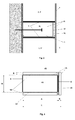
- a building facade with thermal insulation composite system (1) claimed comprising a facade (2), an insulation board (3), in particular an upper (3 ') and a lower (3 ") insulation board, and the claimed invention according to fire bars (45) the fire bolt (45) and the insulation board (3) are fixed to the facade (2) and the fire bolt (45) is adjacent to the insulation board (3), the thinner layer (51) of the fire bolt (45) on the side of the fire bolt (45) is arranged, which faces the facade (2).
- the inventive fire bolt (45), the building facade (1) according to the invention and the use according to the invention of the fire bolt (45) have many advantages.
- the inventive fire barrier (45) fulfills the function of a fire bar.
- the layer (51) made of polystyrene rigid foam - which is part of the firing bolt (45) - due a melting away below the firing bolt (45) burns away and the molten polystyrene drips down, the heat, respectively. the fire by the resulting thin gap between the remaining fire bars (45) and one on the insulation board (3) and fire bars (45) applied plaster (7) do not propagate upwards.
- thermal insulation composite system (1) can also be post-processed without problems and without dust, in order to be completely flat for a subsequent layer, for example a plaster.
- the insulating panels (3) and the thin layer (51) of the firing bar (45) are made of the same material, that is, if they are advantageously both expanded polystyrene (EPS) or extruded polystyrene (XPS ) consist.
- EPS expanded polystyrene
- XPS extruded polystyrene
- protruding corners and edges can be removed without dust in a simple manner.
- adhesion to a subsequent layer such as a plaster layer, is not adversely affected by a thin layer of dust on the fire bar (45) and / or the insulating board (3).
- Occupational safety measures such as wearing a special dust mask, are taken.
- the insulation panels (3) can also be easily cut in the creation of the building facade (1) according to the invention, without running the risk that an integrated fire bar is mistakenly partially or completely cut away. It is also impossible to mount the insulation boards (3) incorrectly on the building facade, since they do not contain a fire bar function.
- the fire bar (45) is preferably in horizontal, i. horizontal, direction attached to the facade (2).
- the fire bar (45) is preferably arranged so that it is adjacent to at least one lower (3 ") and / or upper insulation board (3 '), which is also attached to the facade (2).
- the inventive fire bar (45) comprises a thicker layer (41) of a fire bar (4) based on polyurethane (PUR), polyisocyanurate (PIR), mineral foam, mineral fiber, glass fiber and / or rock wool, a thinner layer (51) of polystyrene Hard foam, in particular of expanded polystyrene (EPS) and / or extruded polystyrene (XPS) and at least one adhesive (10).
- PUR polyurethane
- PIR polyisocyanurate
- mineral foam mineral fiber
- glass fiber glass fiber and / or rock wool
- a thinner layer (51) of polystyrene Hard foam in particular of expanded polystyrene (EPS) and / or extruded polystyrene (XPS) and at least one adhesive (10).
- EPS expanded polystyrene
- XPS extruded polystyrene
- the inventive fire bolt (45) substantially corresponds to a - for example conventional - fire bolt (4) with a fire at the bar (4) fixed layer (5, 51) which opposite to that side of the firing bolt (4), ie the thicker layer (41) , is attached, which is to be attached to the facade (2).
- the thinner layer (51) of the firing bolt (45) corresponds to a layer (5) of, for example, conventional polystyrene rigid foam.
- the fire bar (45) can also optionally comprise at least one further layer (52) of polystyrene hard foam and / or optionally at least one flame-retardant coating (6).
- thinner layer (41) refers to those in cross-section ( Fig. 2 ) A, ie layer thickness A, and the term “thinner layer (51)" on the in cross-section ( Fig. 2 ), ie the layer thickness B, wherein the thicker layer (41), ie the length A, is greater than the thinner layer (51), ie the length B.
- the sum of the length A and the length B essentially yield the Layer thickness C of the inventive fire bar (45), wherein the thickness of a possible adhesive surface, ie the adhesive (10), and optionally the flame-retardant coating (6), between the thicker layer (41) and the thinner layer (51) is negligible.
- the layer (51) of the inventive fire bar has a color which differs from the color of the insulating panels (3).
- inventive firing bolt (45) has at least one side of the thicker layer (41), which is arranged at an angle to the side on which the thinner layer (51) is mounted and which in horizontal position of the firing bolt (45 ) is preferably above and / or below the layer (41), a further layer (52) of polystyrene foam, in particular of expanded polystyrene (EPS) and / or extruded polystyrene (XPS), wherein optionally a flame-retardant coating (6) between the layers (41) and (52) and / or on the layer (52) is mounted.
- EPS expanded polystyrene
- XPS extruded polystyrene
- the polystyrene rigid foam of the thinner layer (51) and the further layer (52) is preferably made of expanded polystyrene (EPS) and / or extruded polystyrene (XPS). It is possible that the fire bar (45) - if it comprises a layer (52) - i) both layers (51) and (52) are made of EPS or XPS, ii) the layer (51) of EPS and the The layer (52) of XPS is, iii) the layer (51) of XPS and the layer (52) of EPS. If the fire bar (45) comprises two or more layers (52), the layers (52) may be EPS and / or XPS.
- EPS expanded polystyrene
- XPS extruded polystyrene
- the fire bar (45) and the layers (4, 41), (5, 51) and (52) of the firing bolt (45) preferably have a substantially rectangular cross-section.
- the fire bar has a height H of about 15 cm to 60 cm, in particular from about 20 cm to 40 cm. To determine the relevant height H of the firing bar (45), only the height of the layer (41) is considered.
- the depth of the thicker layer (41) and the thinner layer (51) applied thereon, and thus the depth, ie the layer thickness C of the entire firing bolt (45), preferably corresponds approximately to the depth, ie the thickness, of the insulation boards (3, 3 ', 3 ").
- the thicker layer (41) has a layer thickness A of about 4 cm to 50 cm or more, preferably 5 cm to 40 cm.
- the layer (5) of polystyrene foam, i. the thinner layer (51) of the firestop (45) has a layer thickness B of 2 to 30 mm, preferably 3 to 20 mm, in particular 4 to 10 mm.
- the thinner layer (51) and / or the layer (52) has a layer thickness B of from 2 to 30 mm, preferably from 2 to 20 mm, in particular from 3 to 10 mm.
- the lengths, heights and layer thicknesses of the individual layers (41, 51, 52) can be measured in a simple manner, for example with a meter, calliper and / or calliper, whereby no pressure is exerted on the layers to be measured, i. they are not pressed together. Those skilled in such measurements of the layer thicknesses are known.
- the inventive fire barrier (45) advantageously consists of at least 70% by volume, preferably of at least 80% by volume, in particular of at least 90% by volume, of the thicker layer (41).
- the determination of the volume of the firing bar (45) and the thicker layer (41) is known to the person skilled in the art and is typically based on the measured lengths, heights and layer thicknesses.
- the thinner layer (51) of polystyrene rigid foam, which is part of the inventive fire bar (45), and optionally the layer (52) may have a density of for example 10 to 60 kg / m 3 , preferably from 15 to 50 kg / m 3 , determined according to DIN EN 1602: 2013-05.
- the inventive fire bolt (45) can also be laterally profiled so that, for example, the right side of a left-hand bolt by means of a step-fold or groove-comb profiling can be inserted seamlessly into the corresponding profiled left side of a right-hand bolt. As a result, the effect of the fire bar is additionally increased.
- the inventive fire barrier (45) is the thinner layer (51), and optionally the layer (52), with the thicker layer (41) by gluing, i. with an adhesive (10), connected.
- a coating (6) is arranged on the thicker layer (41), the thinner layer (51), and optionally the layer (52), is attached to the flame-retardant coating (6) by means of adhesive (10).
- the flame-retardant coating (6) may also be attached to the layer (41) by means of an adhesive (10).
- the coating (6) is preferably used directly in the preparation of the layer (41), i. of the bolt (4) connected to it, whereby no separate adhesive must be used.
- the adhesive 10 is advantageously a one- or two-component (2-K) adhesive based on polyurethane (PU), epoxy hardener, hotmelt adhesive and / or with a double-sided adhesive tape, preferably 2-component PU adhesives Flame retardant, reactive 1-C PU hot-melt adhesive, epoxy adhesive and / or double-sided adhesive tape
- 2-K polyurethane
- PU polyurethane
- epoxy hardener epoxy hardener
- hotmelt adhesive / or with a double-sided adhesive tape
- 2-component PU adhesives Flame retardant, reactive 1-C PU hot-melt adhesive, epoxy adhesive and / or double-sided adhesive tape
- Such adhesives (10) are commercially available and known in the art.
- At least one side of the thicker layer (41), which is arranged at an angle, for example at right angles, to the side on which the thinner layer (51) is mounted has a flame-retardant coating (6). on.
- the flame-retardant coating (6) does not extend over the cross-sectional areas of the firing bar (45), the thicker layer (41) and / or the thinner layer (51).
- the flame-retardant coating (6) preferably consists of non-combustible or very poorly combustible material.
- the flame-retardant coating (6) is preferably made of at least one layer based on inorganic non-woven such as glass fiber fabric, mineral wool and / or mortar, wherein inorganic nonwoven.
- inorganic non-woven such as glass fiber fabric, mineral wool and / or mortar, wherein inorganic nonwoven.
- glass fiber fabric, and / or mineral wool are particularly preferred. Such materials are known to the person skilled in the art.
- the flame retardant coating (6) is advantageously adhered to the thicker layer (41), for example by direct adhesion during foaming, i. in the manufacture of the fire barrier material, i. the thicker layer (41), or with a commercial adhesive (10). This is typically done at the factory.
- the inventive Brandriegel (45) is advantageously prepared industrially.
- the layer (51) of polystyrene foam is preferably factory-fitted to the layer (41) of the firestop (45), i. glued.
- the fire bar (45) additionally comprises one or more layers (52) and / or flame-retardant coating (6).
- the building facade according to the invention with a thermal insulation composite system (1) can be arranged inside and / or outside of buildings.
- the arrangement is in the outdoor area of buildings.
- the building facade (1) comprises an upper (3 ') and lower (3 ") insulating board, the inventive fire bar (45) being connected between the upper (3') and lower (3") insulating boards (3). is arranged and adjacent to this. This arrangement can also be rotated by 90 °, for example, so that the fire bar (45) is fastened, for example, vertically to the facade and the upper (3 ') and lower (3 ") insulation boards are arranged laterally on the fire bar (45). 3, 3 ', 3 ") are typically identical insulation boards and do not differ in their nature.
- insulating board (3) comprises the upper insulating board (3 ') and the lower insulating board (3 ").
- Suitable adhesives (8) and suitable mechanical fastening types such as, for example, screwing or anchoring (9) are known to the person skilled in the art
- Preferred adhesives (8) are, for example, commercially available adhesives based on acrylate, epoxy, polyurethane and / or adhesive foam weakly expanding polyurethane foam adhesive, and / or adhesive mortar based on mineral and / or polymeric binders.
- a flame-retardant coating (6) is provided between the insulation board (3) and the fire barrier (45) according to the invention.
- the flame-retardant coating (6) is part of the firing bolt (45) and mounted on both the upper and lower sides, ie on the side of the firing bolt (45) which adjoins the insulation panel (3).
- a flame-retardant coating (6) also between the insulation board (3) and the fire bar (45) during the construction of the building facade (1) are created.
- a fire bar without coating (6) is preferably used.
- the insulation boards (3, 3 ', 3 ") and the layer (51) applied to the fire bar (45) are coated with a plaster (7).
- facade (2) of the inventive building facade (1) any building or room envelope can be used.
- Non-limiting examples are facades, i. Walls, of concrete, aerated concrete, brick, cement fiber boards, gypsum boards, plasterboard, ceramic tiles, as well as sheet metal, plastic and / or wood cladding.
- the facade (2) may also already contain an existing insulation layer.
- insulation boards such as polymer foam boards and mineral insulation boards can be used as insulation boards 3. If the insulation boards (3, 3 ', 3 ") are not made of polystyrene rigid foam It may be advantageous if, on a side opposite the side fixed to the facade, it is advantageous to use a thin layer of polystyrene foam, in particular a thin layer of expanded polystyrene (EPS) or extruded polystyrene (XPS), are coated.
- EPS expanded polystyrene
- XPS extruded polystyrene
- EPS expanded polystyrene
- XPS extruded polystyrene
- PUR polyurethane
- PIR polyisocyanurate
- PF phenolic resin
- the lower and / or upper insulation board (3, 3 ', 3 ") is an insulation board made of expanded polystyrene (EPS), extruded polystyrene (XPS), polyurethane (PUR), polyisocyanurate (PIR) and / or wood fiber board, wherein the insulation boards polyurethane (PUR), polyisocyanurate (PIR) and / or the wood fiber board may preferably be covered on one side with a layer of polystyrene foam, in particular of expanded polystyrene (EPS) and / or extruded polystyrene (XPS).
- EPS expanded polystyrene
- XPS extruded polystyrene
- XPS extruded polystyrene
- the insulation panels (3, 3 ', 3 ") may for example have a length of 50 cm to several meters, a width of for example 40 cm to 2 m and a thickness of for example 4 cm to 50 cm or more, preferably 5 cm to 40 cm.
- At least one fire bar (45) is advantageously installed in horizontal, i. horizontal, direction attached to the facade (2).
- the fire bar (45) is arranged so that it is adjacent to at least one insulating panel (3), which is also attached to the facade (2).
- an upper insulation board (3 ') is fixed to the facade on the fire bar (45).
- the fire bar (45) is typically deployed horizontally over an entire facade, or even as a horizontal fire bar belt encircling the entire building.
- the fire bar (45) is preferably fixed to a lower insulating panel (3 ") and to the facade, followed by an upper insulating panel (3 '), which comes to rest on the previously attached fire bar (45) facade and optionally attached to the fire bar (45).
- a facade may comprise one or more such circulating fire bolt strips. If multiple fire bars are attached, they are mounted at different heights.
- the inventive building facade with thermal insulation composite system (1) can be prepared substantially in a conventional manner with the difference that instead of a firing bolt (4) of the inventive fire bar (45) is used.
- the insulation boards (3, 3 ', 3 ") and / or the fire bar (45) are glued to the facade (2) with an adhesive (8) and / or additionally mechanically, for example by means of Fastening and / or anchoring (9), attached to the facade (2), whereby the adhesive (8) is advantageously applied to the surface of the insulating board (3, 3 ', 3 ") facing the facade (2) and the firing bolt (45) applied to the facade (2) pressed and adjusted.
- the manner of the mechanical fastening (9) such as screwing and / or anchoring the firing bolt (45) to the facade (2) is known in the art.
- a flame-retardant coating (6) is placed on the lower insulating board (3 "), glued and / or attached.
- a third step the fire bar (45) is placed, glued and / or fastened to the lower insulation board (3 ") or to the flame-retardant coating (6) and fastened to the facade (2) A flame-retardant coating (6) has been placed, glued and / or fastened on the fire bar (45) If a flame-retardant coating (6) has already been connected, for example at the factory, to the fire bar (45), the second and fourth steps are omitted.
- the upper insulating panel (3 ') which optionally rests on the fire bar (45) or on the flame-retardant coating (6), is fastened to the facade (2) optional further, sixth step, which can also take place optionally after the curing of adhesives used, may possibly be any unevenness of the surface of the created groundedstedämmv be removed.
- the building facade according to the invention typically and advantageously consists of the same material as polystyrene hard foam, in particular EPS or XPS, this step is particularly simple and without the formation of unwanted dust and therefore also without adversely affecting the adhesion.
- a conventional plaster is then applied in a conventional manner to the surface freed from unevenness, in which optionally a glass fiber mesh can be embedded for reinforcement.
- the fire catch (45) in order to produce the thermal insulation composite system of the building façade (1) according to the invention, in a first step the fire catch (45) is fastened to the facade (2), in particular above building openings such as doors and / or windows.
- a flame retardant coating (6) may be applied in an optional further step on the bottom and / or top of the firing bolt (45).
- the layer (51) and / or a flame-retardant coating (6) before, for example, factory-fixed to the fire bar (45), the attachment of the coating (6) is unnecessary.
- the upper insulation board (3 ') on the fire bolt (45) attached to the facade (2) in a first step the fire catch (45) is fastened to the facade (2), in particular above building openings such as doors and / or windows.
- a conventional plaster (7) is applied to the unevenness-free surface in a conventional manner, in which optionally a fiber optic network can be embedded for reinforcement.
Landscapes
- Engineering & Computer Science (AREA)
- Architecture (AREA)
- Physics & Mathematics (AREA)
- Electromagnetism (AREA)
- Civil Engineering (AREA)
- Structural Engineering (AREA)
- Acoustics & Sound (AREA)
- Building Environments (AREA)
Priority Applications (1)
| Application Number | Priority Date | Filing Date | Title |
|---|---|---|---|
| EP15174905.8A EP2963200B1 (fr) | 2014-07-03 | 2015-07-01 | Façade de bâtiment dotée d'élément pare-feu |
Applications Claiming Priority (2)
| Application Number | Priority Date | Filing Date | Title |
|---|---|---|---|
| EP14175639 | 2014-07-03 | ||
| EP15174905.8A EP2963200B1 (fr) | 2014-07-03 | 2015-07-01 | Façade de bâtiment dotée d'élément pare-feu |
Publications (3)
| Publication Number | Publication Date |
|---|---|
| EP2963200A1 true EP2963200A1 (fr) | 2016-01-06 |
| EP2963200B1 EP2963200B1 (fr) | 2023-08-09 |
| EP2963200C0 EP2963200C0 (fr) | 2023-08-09 |
Family
ID=51176132
Family Applications (1)
| Application Number | Title | Priority Date | Filing Date |
|---|---|---|---|
| EP15174905.8A Active EP2963200B1 (fr) | 2014-07-03 | 2015-07-01 | Façade de bâtiment dotée d'élément pare-feu |
Country Status (1)
| Country | Link |
|---|---|
| EP (1) | EP2963200B1 (fr) |
Cited By (1)
| Publication number | Priority date | Publication date | Assignee | Title |
|---|---|---|---|---|
| WO2019084150A1 (fr) * | 2016-10-24 | 2019-05-02 | Firefree Coatings, Inc. | Installations rétroactives de protection contre l'incendie pour immeubles |
Citations (4)
| Publication number | Priority date | Publication date | Assignee | Title |
|---|---|---|---|---|
| AT5285U1 (de) | 2001-01-11 | 2002-05-27 | Prima Bau Und Daemmsysteme Ges | Wärmedämmplatte |
| AT7757U1 (de) | 2003-10-23 | 2005-08-25 | Prima Bau Und Daemmsysteme Ges | Wärmedämmplatte aus hartschaum |
| DE202007007225U1 (de) | 2006-05-22 | 2007-07-26 | Stahlton Bauteile Ag | Bauelement für ein Wärmedämmverbundsystem |
| EP2706160A2 (fr) | 2012-09-05 | 2014-03-12 | Gonon Isolation AG (SA) | Panneau de façade et paroi de façade formée de panneaux de façade |
-
2015
- 2015-07-01 EP EP15174905.8A patent/EP2963200B1/fr active Active
Patent Citations (4)
| Publication number | Priority date | Publication date | Assignee | Title |
|---|---|---|---|---|
| AT5285U1 (de) | 2001-01-11 | 2002-05-27 | Prima Bau Und Daemmsysteme Ges | Wärmedämmplatte |
| AT7757U1 (de) | 2003-10-23 | 2005-08-25 | Prima Bau Und Daemmsysteme Ges | Wärmedämmplatte aus hartschaum |
| DE202007007225U1 (de) | 2006-05-22 | 2007-07-26 | Stahlton Bauteile Ag | Bauelement für ein Wärmedämmverbundsystem |
| EP2706160A2 (fr) | 2012-09-05 | 2014-03-12 | Gonon Isolation AG (SA) | Panneau de façade et paroi de façade formée de panneaux de façade |
Cited By (1)
| Publication number | Priority date | Publication date | Assignee | Title |
|---|---|---|---|---|
| WO2019084150A1 (fr) * | 2016-10-24 | 2019-05-02 | Firefree Coatings, Inc. | Installations rétroactives de protection contre l'incendie pour immeubles |
Also Published As
| Publication number | Publication date |
|---|---|
| EP2963200B1 (fr) | 2023-08-09 |
| EP2963200C0 (fr) | 2023-08-09 |
Similar Documents
| Publication | Publication Date | Title |
|---|---|---|
| EP3256660B1 (fr) | Élément d'étanchéité de jointure et dispositif d'étanchéité comprenant un élément d'étanchéité de jointure de ce type | |
| DE3011019C2 (fr) | ||
| EP2726680B1 (fr) | Construction de façade pour l'isolation thermique et l'habillage de parois de bâtiments, et procédé de fabrication d'une telle construction de façade | |
| EP1500752A2 (fr) | Elément d'isolation et système d'isolation thermique | |
| DE102012221746B4 (de) | Wandheizelement | |
| EP3587699B1 (fr) | Paroi extérieure | |
| DE19951105C2 (de) | Wärme- und/oder Schalldämmelement | |
| DE19643618A1 (de) | Wärmedämmverbundsystem | |
| EP2067905B1 (fr) | Elément d'habillage préfabriqué pour un mur extérieur dans la zone d'un intrados de fenêtre ou de porte | |
| EP2963200B1 (fr) | Façade de bâtiment dotée d'élément pare-feu | |
| DE202012100418U1 (de) | Gebäudefassade mit Riegelelement und Riegelelement | |
| DE102011053499A1 (de) | Wärmedämmverbundeinrichtung | |
| EP1936056A2 (fr) | Composant plat | |
| EP1008697A2 (fr) | Elément d'isolation thermique et/ou phonique | |
| DE102004042301B4 (de) | Dichtprofil zur kantenumfassenden Anbringung an freien Rändern von Wärmedämmplatten | |
| DE102015015604B4 (de) | Aufnahmeelement für eine Beschattungseinrichtung und Verfahren zum Befestigen eines solchen an der Außenseite eines Gebäudes | |
| EP1295998B1 (fr) | Isolation acoustique et thermique; Elément d'isolation et lamelle de fibres minérales | |
| DE19806454C2 (de) | Dämmstoffelement | |
| DE102012111421A1 (de) | Wärmedämmverbundsystem umfassend eine auf eine Mauerwerksfläche anbringbare Dämmstoffschicht sowie Verfahren zur Herstellung eines Wärmedämmverbundsystems | |
| EP2754767A1 (fr) | Système d'isolation avec intercalaire | |
| DE10232446A1 (de) | Verbundmauerstein | |
| DE19857383A1 (de) | Wärme- und/oder Schalldämmelement | |
| DE10227736A1 (de) | Wärme- oder Schalldämmung, Dämmstoffelement und Mineralfaserlamelle | |
| DE3005279C2 (fr) | ||
| DE102014015829A1 (de) | Fassadendämmelement |
Legal Events
| Date | Code | Title | Description |
|---|---|---|---|
| PUAI | Public reference made under article 153(3) epc to a published international application that has entered the european phase |
Free format text: ORIGINAL CODE: 0009012 |
|
| AK | Designated contracting states |
Kind code of ref document: A1 Designated state(s): AL AT BE BG CH CY CZ DE DK EE ES FI FR GB GR HR HU IE IS IT LI LT LU LV MC MK MT NL NO PL PT RO RS SE SI SK SM TR |
|
| AX | Request for extension of the european patent |
Extension state: BA ME |
|
| 17P | Request for examination filed |
Effective date: 20160208 |
|
| RBV | Designated contracting states (corrected) |
Designated state(s): AL AT BE BG CH CY CZ DE DK EE ES FI FR GB GR HR HU IE IS IT LI LT LU LV MC MK MT NL NO PL PT RO RS SE SI SK SM TR |
|
| STAA | Information on the status of an ep patent application or granted ep patent |
Free format text: STATUS: EXAMINATION IS IN PROGRESS |
|
| 17Q | First examination report despatched |
Effective date: 20180117 |
|
| STAA | Information on the status of an ep patent application or granted ep patent |
Free format text: STATUS: EXAMINATION IS IN PROGRESS |
|
| STAA | Information on the status of an ep patent application or granted ep patent |
Free format text: STATUS: EXAMINATION IS IN PROGRESS |
|
| GRAP | Despatch of communication of intention to grant a patent |
Free format text: ORIGINAL CODE: EPIDOSNIGR1 |
|
| STAA | Information on the status of an ep patent application or granted ep patent |
Free format text: STATUS: GRANT OF PATENT IS INTENDED |
|
| RIC1 | Information provided on ipc code assigned before grant |
Ipc: E04B 1/76 20060101ALN20230207BHEP Ipc: E04B 1/94 20060101AFI20230207BHEP |
|
| INTG | Intention to grant announced |
Effective date: 20230303 |
|
| GRAS | Grant fee paid |
Free format text: ORIGINAL CODE: EPIDOSNIGR3 |
|
| GRAA | (expected) grant |
Free format text: ORIGINAL CODE: 0009210 |
|
| STAA | Information on the status of an ep patent application or granted ep patent |
Free format text: STATUS: THE PATENT HAS BEEN GRANTED |
|
| AK | Designated contracting states |
Kind code of ref document: B1 Designated state(s): AL AT BE BG CH CY CZ DE DK EE ES FI FR GB GR HR HU IE IS IT LI LT LU LV MC MK MT NL NO PL PT RO RS SE SI SK SM TR |
|
| REG | Reference to a national code |
Ref country code: GB Ref legal event code: FG4D Free format text: NOT ENGLISH |
|
| REG | Reference to a national code |
Ref country code: CH Ref legal event code: EP |
|
| REG | Reference to a national code |
Ref country code: IE Ref legal event code: FG4D Free format text: LANGUAGE OF EP DOCUMENT: GERMAN |
|
| REG | Reference to a national code |
Ref country code: DE Ref legal event code: R096 Ref document number: 502015016527 Country of ref document: DE |
|
| U01 | Request for unitary effect filed |
Effective date: 20230830 |
|
| U07 | Unitary effect registered |
Designated state(s): AT BE BG DE DK EE FI FR IT LT LU LV MT NL PT SE SI Effective date: 20230905 |
|
| PG25 | Lapsed in a contracting state [announced via postgrant information from national office to epo] |
Ref country code: IS Free format text: LAPSE BECAUSE OF FAILURE TO SUBMIT A TRANSLATION OF THE DESCRIPTION OR TO PAY THE FEE WITHIN THE PRESCRIBED TIME-LIMIT Effective date: 20231209 |
|
| PG25 | Lapsed in a contracting state [announced via postgrant information from national office to epo] |
Ref country code: RS Free format text: LAPSE BECAUSE OF FAILURE TO SUBMIT A TRANSLATION OF THE DESCRIPTION OR TO PAY THE FEE WITHIN THE PRESCRIBED TIME-LIMIT Effective date: 20230809 Ref country code: NO Free format text: LAPSE BECAUSE OF FAILURE TO SUBMIT A TRANSLATION OF THE DESCRIPTION OR TO PAY THE FEE WITHIN THE PRESCRIBED TIME-LIMIT Effective date: 20231109 Ref country code: IS Free format text: LAPSE BECAUSE OF FAILURE TO SUBMIT A TRANSLATION OF THE DESCRIPTION OR TO PAY THE FEE WITHIN THE PRESCRIBED TIME-LIMIT Effective date: 20231209 Ref country code: HR Free format text: LAPSE BECAUSE OF FAILURE TO SUBMIT A TRANSLATION OF THE DESCRIPTION OR TO PAY THE FEE WITHIN THE PRESCRIBED TIME-LIMIT Effective date: 20230809 |
|
| PG25 | Lapsed in a contracting state [announced via postgrant information from national office to epo] |
Ref country code: PL Free format text: LAPSE BECAUSE OF FAILURE TO SUBMIT A TRANSLATION OF THE DESCRIPTION OR TO PAY THE FEE WITHIN THE PRESCRIBED TIME-LIMIT Effective date: 20230809 |
|
| PG25 | Lapsed in a contracting state [announced via postgrant information from national office to epo] |
Ref country code: ES Free format text: LAPSE BECAUSE OF FAILURE TO SUBMIT A TRANSLATION OF THE DESCRIPTION OR TO PAY THE FEE WITHIN THE PRESCRIBED TIME-LIMIT Effective date: 20230809 |
|
| PG25 | Lapsed in a contracting state [announced via postgrant information from national office to epo] |
Ref country code: SM Free format text: LAPSE BECAUSE OF FAILURE TO SUBMIT A TRANSLATION OF THE DESCRIPTION OR TO PAY THE FEE WITHIN THE PRESCRIBED TIME-LIMIT Effective date: 20230809 Ref country code: RO Free format text: LAPSE BECAUSE OF FAILURE TO SUBMIT A TRANSLATION OF THE DESCRIPTION OR TO PAY THE FEE WITHIN THE PRESCRIBED TIME-LIMIT Effective date: 20230809 Ref country code: ES Free format text: LAPSE BECAUSE OF FAILURE TO SUBMIT A TRANSLATION OF THE DESCRIPTION OR TO PAY THE FEE WITHIN THE PRESCRIBED TIME-LIMIT Effective date: 20230809 Ref country code: CZ Free format text: LAPSE BECAUSE OF FAILURE TO SUBMIT A TRANSLATION OF THE DESCRIPTION OR TO PAY THE FEE WITHIN THE PRESCRIBED TIME-LIMIT Effective date: 20230809 Ref country code: SK Free format text: LAPSE BECAUSE OF FAILURE TO SUBMIT A TRANSLATION OF THE DESCRIPTION OR TO PAY THE FEE WITHIN THE PRESCRIBED TIME-LIMIT Effective date: 20230809 |
|
| REG | Reference to a national code |
Ref country code: DE Ref legal event code: R097 Ref document number: 502015016527 Country of ref document: DE |
|
| PLBE | No opposition filed within time limit |
Free format text: ORIGINAL CODE: 0009261 |
|
| STAA | Information on the status of an ep patent application or granted ep patent |
Free format text: STATUS: NO OPPOSITION FILED WITHIN TIME LIMIT |
|
| 26N | No opposition filed |
Effective date: 20240513 |
|
| U20 | Renewal fee paid [unitary effect] |
Year of fee payment: 10 Effective date: 20240731 |