EP2962894B1 - Kindersicherheitssitz - Google Patents
Kindersicherheitssitz Download PDFInfo
- Publication number
- EP2962894B1 EP2962894B1 EP15173654.3A EP15173654A EP2962894B1 EP 2962894 B1 EP2962894 B1 EP 2962894B1 EP 15173654 A EP15173654 A EP 15173654A EP 2962894 B1 EP2962894 B1 EP 2962894B1
- Authority
- EP
- European Patent Office
- Prior art keywords
- side wall
- energy absorption
- child safety
- absorption unit
- safety seat
- Prior art date
- Legal status (The legal status is an assumption and is not a legal conclusion. Google has not performed a legal analysis and makes no representation as to the accuracy of the status listed.)
- Not-in-force
Links
Images


Classifications
-
- B—PERFORMING OPERATIONS; TRANSPORTING
- B60—VEHICLES IN GENERAL
- B60N—SEATS SPECIALLY ADAPTED FOR VEHICLES; VEHICLE PASSENGER ACCOMMODATION NOT OTHERWISE PROVIDED FOR
- B60N2/00—Seats specially adapted for vehicles; Arrangement or mounting of seats in vehicles
- B60N2/24—Seats specially adapted for vehicles; Arrangement or mounting of seats in vehicles for particular purposes or particular vehicles
- B60N2/26—Seats specially adapted for vehicles; Arrangement or mounting of seats in vehicles for particular purposes or particular vehicles for children
- B60N2/28—Seats readily mountable on, and dismountable from, existing seats or other parts of the vehicle
- B60N2/2884—Seats readily mountable on, and dismountable from, existing seats or other parts of the vehicle with protection systems against abnormal g-forces
-
- B—PERFORMING OPERATIONS; TRANSPORTING
- B60—VEHICLES IN GENERAL
- B60N—SEATS SPECIALLY ADAPTED FOR VEHICLES; VEHICLE PASSENGER ACCOMMODATION NOT OTHERWISE PROVIDED FOR
- B60N2/00—Seats specially adapted for vehicles; Arrangement or mounting of seats in vehicles
- B60N2/24—Seats specially adapted for vehicles; Arrangement or mounting of seats in vehicles for particular purposes or particular vehicles
- B60N2/26—Seats specially adapted for vehicles; Arrangement or mounting of seats in vehicles for particular purposes or particular vehicles for children
- B60N2/28—Seats readily mountable on, and dismountable from, existing seats or other parts of the vehicle
- B60N2/2851—Seats readily mountable on, and dismountable from, existing seats or other parts of the vehicle provided with head-rests
-
- B—PERFORMING OPERATIONS; TRANSPORTING
- B60—VEHICLES IN GENERAL
- B60N—SEATS SPECIALLY ADAPTED FOR VEHICLES; VEHICLE PASSENGER ACCOMMODATION NOT OTHERWISE PROVIDED FOR
- B60N2/00—Seats specially adapted for vehicles; Arrangement or mounting of seats in vehicles
- B60N2/24—Seats specially adapted for vehicles; Arrangement or mounting of seats in vehicles for particular purposes or particular vehicles
- B60N2/26—Seats specially adapted for vehicles; Arrangement or mounting of seats in vehicles for particular purposes or particular vehicles for children
- B60N2/28—Seats readily mountable on, and dismountable from, existing seats or other parts of the vehicle
- B60N2/2872—Seats readily mountable on, and dismountable from, existing seats or other parts of the vehicle provided with side rests
-
- B—PERFORMING OPERATIONS; TRANSPORTING
- B60—VEHICLES IN GENERAL
- B60N—SEATS SPECIALLY ADAPTED FOR VEHICLES; VEHICLE PASSENGER ACCOMMODATION NOT OTHERWISE PROVIDED FOR
- B60N2/00—Seats specially adapted for vehicles; Arrangement or mounting of seats in vehicles
- B60N2/24—Seats specially adapted for vehicles; Arrangement or mounting of seats in vehicles for particular purposes or particular vehicles
- B60N2/26—Seats specially adapted for vehicles; Arrangement or mounting of seats in vehicles for particular purposes or particular vehicles for children
- B60N2/28—Seats readily mountable on, and dismountable from, existing seats or other parts of the vehicle
- B60N2/2875—Seats readily mountable on, and dismountable from, existing seats or other parts of the vehicle inclinable, as a whole or partially
- B60N2/2878—Seats readily mountable on, and dismountable from, existing seats or other parts of the vehicle inclinable, as a whole or partially the back-rest being inclinable
-
- B—PERFORMING OPERATIONS; TRANSPORTING
- B60—VEHICLES IN GENERAL
- B60N—SEATS SPECIALLY ADAPTED FOR VEHICLES; VEHICLE PASSENGER ACCOMMODATION NOT OTHERWISE PROVIDED FOR
- B60N2/00—Seats specially adapted for vehicles; Arrangement or mounting of seats in vehicles
- B60N2/24—Seats specially adapted for vehicles; Arrangement or mounting of seats in vehicles for particular purposes or particular vehicles
- B60N2/42—Seats specially adapted for vehicles; Arrangement or mounting of seats in vehicles for particular purposes or particular vehicles the seat constructed to protect the occupant from the effect of abnormal g-forces, e.g. crash or safety seats
- B60N2/4207—Seats specially adapted for vehicles; Arrangement or mounting of seats in vehicles for particular purposes or particular vehicles the seat constructed to protect the occupant from the effect of abnormal g-forces, e.g. crash or safety seats characterised by the direction of the g-forces
- B60N2/4235—Seats specially adapted for vehicles; Arrangement or mounting of seats in vehicles for particular purposes or particular vehicles the seat constructed to protect the occupant from the effect of abnormal g-forces, e.g. crash or safety seats characterised by the direction of the g-forces transversal
-
- B—PERFORMING OPERATIONS; TRANSPORTING
- B60—VEHICLES IN GENERAL
- B60N—SEATS SPECIALLY ADAPTED FOR VEHICLES; VEHICLE PASSENGER ACCOMMODATION NOT OTHERWISE PROVIDED FOR
- B60N2/00—Seats specially adapted for vehicles; Arrangement or mounting of seats in vehicles
- B60N2/24—Seats specially adapted for vehicles; Arrangement or mounting of seats in vehicles for particular purposes or particular vehicles
- B60N2/42—Seats specially adapted for vehicles; Arrangement or mounting of seats in vehicles for particular purposes or particular vehicles the seat constructed to protect the occupant from the effect of abnormal g-forces, e.g. crash or safety seats
- B60N2/427—Seats or parts thereof displaced during a crash
- B60N2/42709—Seats or parts thereof displaced during a crash involving residual deformation or fracture of the structure
Definitions
- the invention relates to a child safety seat with laterally limited by sidewalls seat, backrest and possibly headrest, especially child safety seat for infants and children up to 14 years with a head end and a foot end having seat / -liegeschale, which has raised sidewalls in side areas, wherein at least in Area of the side walls at least one energy-absorbing measure is provided, according to claim 1.
- Numerous child safety seats are known from the prior art. These are used in particular for the safe transport of children in vehicles such.
- the head of the infant or child in a child safety seat is a particularly vulnerable area.
- constructional precautions are preferably to be taken in order to be able to best protect the infant and / or the child along the back and sitting area from forces acting on the child or the infant.
- a child safety seat according to the preamble of claim 1 is for example from the document WO 2014/053009 A1 known.
- the present invention seeks to provide a further developed, a particularly high protection offering child safety seat for a baby or a child up to 14 years.
- the described object is initially achieved by a child safety seat according to claim 1.
- a child safety seat is laterally limited by side walls seating area, backrest and possibly headrest, in particular a child safety seat for infants and children up to 14 years, with a head end and a foot end having seat / -liegeschale having sidewalls raised side walls, wherein at least at least one energy-absorbing measure is provided in the region of the side walls.
- a child safety seat is to be assumed in the vast majority by default of a trained headrest.
- infant safety seats for infants and children up to the age of 14 have a seat / cradle that includes a head end, a foot end, and sidewalls raised in side areas.
- the child safety seat according to the invention is based on the fact that at least one energy-absorbing measure is provided at least in the region of the side walls.
- the seat / -liegeschale may be formed for example of plastic and / or metal and / or wood.
- the at least one energy-absorbing measure in the form of at least one arranged on a side wall of the seating area and / or backrest and / or headrest energy absorption unit with approximately perpendicular and / or parallel to the extension of the side wall extending, deformation elements, in particular Deformationsvor- and / or recesses , educated.
- the energy absorbing measure is an energy absorption unit formed on at least one side wall of the seat portion and / or the seat back and / or headrest.
- the at least one energy absorption unit comprises deformation elements which extend approximately perpendicularly and / or possibly parallel to the extension of the side wall, in particular deformation advances and / or recesses.
- the deformation elements, in particular the Deformationsvor- and / or recesses can deform in an accident situation and absorb energy accordingly.
- the deformation reduces the impact energy and reduces the acceleration on body parts of the infant or child in the child safety seat.
- the at least one energy absorption unit is designed as a three-dimensionally shaped molded body, in particular made of a film, in particular of plastic and / or cardboard and / or metal.
- the three-dimensionally shaped molded body comprises a base surface and projections and / or recesses formed therefrom which are deformable when absorbed by energy.
- the projections and / or recesses may be formed, for example, tenon or web-like. This is not an exhaustive list of possible forms of education of the advantages and / or recesses. Here are a variety of training opportunities and / or geometric shapes conceivable.
- the projections and / or recesses may also be tubular.
- the projections and / or recesses have a greater longitudinal extent than transverse extent.
- the longitudinal extent defines the depth of the deformation elements or deformation advances and / or recesses extending approximately perpendicularly and / or parallel to a side wall.
- the transverse extent of the projections and / or recesses or deformation Vor- and / or recesses limits the cross section of these deformation elements.
- Such projections and / or recesses or Deformationsvor- and / or recesses can reduce a very high proportion of the impact energy in the event of an impact; For example, the acceleration to a body part of the infant or the child, in particular the acceleration to the head of the infant or child, can be reduced by about half.
- At at least one edge of the base of the three-dimensionally shaped molded body is pulled up from this a side wall, so that together with the base area a kind of "absorption box or absorption box" is formed or formed.
- side walls are formed and pulled up on at least two edges of the base of the three-dimensionally shaped molding.
- On at least one side wall of the three-dimensionally shaped molded body web-like or peg-like or tubular projections may extend, which thus also extend approximately perpendicular to the extension of the side wall of the child safety seat, and thus act similarly energy absorbing as the formed from the base out front and / or recesses.
- the energy absorption unit is in each case part of a separate side wall element which is designed to be insertable and exchangeable on the side of the backrest and / or seat area and / or headrest facing the body and / or head of the child.
- the energy absorption unit may be formed as a separate component, which can be inserted into a corresponding recess of the backrest and / or the seat area and / or the headrest and possibly interchangeable.
- the energy absorption unit may comprise fastening means, which are formed corresponding to fastening means of the side wall of the backrest and / or the seat portion and / or the headrest.
- the energy absorption unit can be connected by tongue and groove connection with the side wall or within a recess of the side wall. The formation of such a tongue and groove connection can be variable, d. H. the groove can be formed both on the energy absorption unit and in the side wall or in the recess of the side wall. The same applies to the spring.
- At least two energy absorption units are provided in the side walls of the seat portion and / or the backrest and / or the headrest, which are arranged facing each other symmetrically to an imaginary center longitudinal axis of the child seat.
- the box- or box-like shape of the body made of plastic and / or cardboard and / or metal or a film made of plastic and / or cardboard and / or metal can therefore also have only in the base and / or side surfaces formed perforations.
- the trained perforations make it possible to advance defined deformation of the base and / or side surfaces, so that due to the deformation of the ground and / or side surfaces acting in the event of an impact impact energy is reduced and the acceleration is reduced to body parts of the present in a child safety seat infant and / or child ,
- the perforations can also be referred to as recesses.
- the perforations or recesses may have a round and / or elliptical and / or a rectangular and / or a square and / or a polygonal cross section.
- the arrangement of the recesses or perforations to each other can be made variable.
- at least three, in particular at least four, in particular at least five, in particular at least six, in particular at least seven, perforations or recesses are formed in the energy absorption unit.
- the arrangement of the perforations or recesses relative to one another preferably takes place in such a manner that the base and / or side surface provided with the perforations or recesses is maximally deformable in the event of an impact and can thus reduce a maximum possible impact energy.
- a child safety seat can be formed with at least one exchangeable energy absorption unit. After an impact or a deformation of the energy absorption unit, the inventive Child safety seat thus be provided with a new energy absorption unit.
- At least two are in the side walls of the seating area and / or the backrest and / or the headrest
- Energy absorption provided, which are arranged facing each other symmetrically to an imaginary center longitudinal axis of the child seat. This applies in particular to the formation of an energy-absorbing measure in the region of the side wall or side cheek of a headrest.
- Fig. 1 shows a side wall 10 of an inventive headrest, wherein the side cheek 10 a headrest as a side wall of a Headrest can be called.
- the headrest according to the invention has at least one energy-absorbing measure at least in the region of the side walls or in the region of the side cheeks 10.
- This energy-absorbing measure is in the form of an energy absorption unit 15 arranged on a side wall or side wall 10 of the headrest.
- the energy absorption unit 15 forms a separate component or is to be understood as a separate side wall element.
- the energy absorption unit 15 is arranged on the side of the side cheek 10 facing the head of the infant or the child.
- the energy absorption unit 15 fits in flush with the side wall 10. The free, the head of a child facing surface of the energy absorption unit 15 is thus flush with the corresponding surface 21 of the side wall 10.
- the energy absorption unit 15 may be formed by a molded body formed from a body, in particular from a film, from plastic and / or cardboard and / or metal.
- the energy absorption unit 15 may be formed of the same material as the side wall 10.
- the energy absorption unit 15 is to be understood in the example shown as a separate component. Accordingly, it is a separate side wall element or the energy absorption unit 15 is inserted into the side wall or side cheek 10 of the headrest. It is thus possible to exchange defective energy absorption units 15 or used energy absorption units 15 and to replace them with new or undamaged energy absorption units.
- the energy absorption unit 15 has fastening means 23. These attachment means 23 correspond to attachment or locking means 24 of the side cheek 10 or side wall (see Fig. 1b ).
- the attachment or locking of the energy absorption unit 15 on the side wall 10 is realized by a tongue and groove connection.
- the attachment means 23 of the energy absorption unit 15 is according to the in the Fig. 1a to 1c illustrated embodiment formed as an elongated spring. In a recess 18 of the side wall 10 corresponding recesses or grooves 24 are formed to the springs 23.
- the energy absorption unit 15 is formed as a three-dimensionally shaped molded body.
- This can be formed, for example, by shaping a body, in particular a film, of plastic and / or cardboard and / or metal.
- the three-dimensionally shaped molded body has a base surface 30 and protrusions 31 formed from this base surface 30.
- the projections 31 are deformable when absorbed by energy.
- the projections 31 are of pin-shaped design, ie the base of the projections is substantially square.
- the longitudinal extent or depth of the protrusions 31 formed out is greater than the transverse extent, ie greater than the base area cross section thereof.
- the deformation projections 31 are hollow, for example, when formed from a film.
- the filling of the projections 31 with plastically deformable material, for. B. PU foam or the like is conceivable.
- the deformation projections 31 extend approximately perpendicular to the base surface 30 of the energy absorption unit 15.
- a side wall 32 is pulled up.
- a side wall 33 is pulled up.
- a three-dimensionally shaped shaped article is formed in the manner of an absorption box or an absorption box.
- the openings formed there are closed to the deformation projections 31 by a cover film, so that on this side a continuous smooth surface is formed (s. Fig. 1a ).
- the surface may also be structured and / or roughened.
- the energy absorption unit 15 or the three-dimensionally shaped shaped body has a substantially rectangular shape, wherein the one side wall 32 extends slightly arcuate corresponding to the contour of the associated side wall or side wall 10 of the headrest in the region of the recess into which the energy absorption unit 15 is to be inserted ,
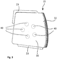
- FIG. 3 another embodiment of an energy absorption unit is shown.
- This is designed as a box-shaped or box-shaped body made of plastic and / or cardboard and / or metal, wherein in the base 30 of the energy absorption unit 15 perforations 40 may be formed.
- the box-shaped or box-shaped body is originally a foil.
- the perforations or recesses or recesses may be formed identically.
- the perforations 40 are each formed circular.
- five circular perforations 40 are formed lying approximately on a circular line.
- the illustrated energy absorption unit 15 can additionally be formed with projections and / or recesses formed out of the base or bottom surface 30. The formation of perforations and / or projections and / or recesses in the area of the side walls 32 of the box-like energy absorption unit 15 that are raised on all sides is also conceivable.
- the circular formation of the perforations 40 is merely an exemplary representation.
- the perforations can also be rectangular and / or elliptical and / or have square and / or polygonal cross sections.
- the arrangements of the perforations 40 to each other is variable and can be designed, for example, depending on the position of the energy absorption unit 15 in the child safety seat according to the invention.
- a possible energy absorption unit 15 is formed as a separate component and thus used in the side wall or in the side cheek 10 of a headrest.
- energy absorption units of the type described can also be arranged at suitable locations on the side and / or rear wall of a child seat.
Landscapes
- Engineering & Computer Science (AREA)
- Aviation & Aerospace Engineering (AREA)
- Transportation (AREA)
- Mechanical Engineering (AREA)
- Health & Medical Sciences (AREA)
- General Health & Medical Sciences (AREA)
- Child & Adolescent Psychology (AREA)
- Seats For Vehicles (AREA)
- Dentistry (AREA)
Description
- Die Erfindung betrifft einen Kindersicherheitssitz mit seitlich durch Seitenwände begrenzten Sitzbereich, Rückenlehne und ggf. Kopfstütze, insbesondere Kindersicherheitssitz für Säuglinge und Kinder bis 14 Jahre mit einer ein Kopfende und ein Fußende aufweisenden Sitz/-liegeschale, welche in Seitenbereichen hochgezogene Seitenwände aufweist, wobei wenigstens im Bereich der Seitenwände wenigstens eine energieabsorbierende Maßnahme vorgesehen ist, gemäß Anspruch 1.
- Aus dem Stand der Technik sind zahlreiche Kindersicherheitssitze bekannt. Diese dienen insbesondere dem sicheren Transport von Kindern in Fahrzeugen wie z. B. Kraftfahrzeugen. Im Falle eines Unfalls des Kraftfahrzeuges ist der Kopf des darin in einem Kindersicherheitssitz befindlichen Säuglings bzw. Kindes ein besonders gefährdeter Bereich. Hier gilt es besondere konstruktive Vorkehrungen zu treffen, um den Kopf des Kindes bei einem Unfall des Kraftfahrzeuges bestmöglich zu schützen. Auch im Bereich der Rückenlehne bzw. des Sitzbereiches eines Kindersicherheitssitzes sind vorzugsweise derartige konstruktive Vorkehrungen zu treffen, um den Säugling und/oder das Kind entlang des Rücken- und Sitzbereiches bestmöglich vor, auf das Kind bzw. den Säugling einwirkenden, Kräften schützen zu können.
- Ein Kindersicherheitssitz nach dem Oberbegriff des Anspruchs 1 ist z.B. aus dem Dokument
WO 2014/053009 A1 bekannt. - Aus dem Vorgenannten liegt der Erfindung die Aufgabe zugrunde, einen weiterentwickelten, einen besonders hohen Schutz bietenden Kindersicherheitssitz für einen Säugling oder ein Kind bis 14 Jahre bereitzustellen.
- Die beschriebene Aufgabe wird zunächst durch einen Kindersicherheitssitz gemäß Anspruch 1 gelöst.
- Demnach ist ein Kindersicherheitssitz mit seitlich durch Seitenwände begrenzten Sitzbereich, Rückenlehne und ggf. Kopfstütze, insbesondere ein Kindersicherheitssitz für Säuglinge und Kinder bis 14 Jahre, mit einer ein Kopfende und ein Fußende aufweisenden Sitz/-liegeschale, welche in Seitenbereichen hochgezogene Seitenwände aufweist, wobei wenigstens im Bereich der Seitenwände wenigstens eine energieabsorbierende Maßnahme vorgesehen ist, angegeben. Bei Kindersicherheitssitzen ist in den überwiegenden Fällen standardmäßig von einer ausgebildeten Kopfstütze auszugehen. Oftmals weisen Kindersicherheitssitze für Säuglinge und Kinder bis 14 Jahre eine Sitz/- liegeschale auf, die ein Kopfende, ein Fußende, sowie in Seitenbereichen hochgezogene Seitenwände umfasst. Der erfindungsgemäße Kindersicherheitssitz beruht darauf, dass wenigstens im Bereich der Seitenwände wenigstens eine energieabsorbierende Maßnahme vorgesehen ist.
- Die Sitz/-liegeschale kann beispielsweise aus Kunststoff und/oder Metall und/oder Holz gebildet sein.
- Erfindungsgemäß ist die wenigstens eine energieabsorbierende Maßnahme in Form von wenigstens einer an einer Seitenwand von Sitzbereich und/oder Rückenlehne und/oder Kopfstütze angeordnete Energieabsorptionseinheit mit sich etwa senkrecht und/oder parallel zur Erstreckung der Seitenwand erstreckenden, Deformationselementen, insbesondere Deformationsvor- und/oder rücksprüngen, ausgebildet. Mit anderen Worten ist die energieabsorbierende Maßnahme eine Energieabsorptionseinheit, die an wenigstens einer Seitenwand des Sitzbereichs und/oder der Rückenlehne und/oder Kopfstütze ausgebildet ist. Die wenigstens eine Energieabsorptionseinheit umfasst sich etwa senkrecht und/oder ggf. parallel zur Erstreckung der Seitenwand erstreckende Deformationselemente, insbesondere Deformationsvor- und/oder rücksprünge. Die Deformationselemente, insbesondere die Deformationsvor- und/oder rücksprünge können bei einer Unfallsituation deformieren und entsprechend Energie absorbieren.
- Durch die Deformierung wird die Aufprallenergie abgebaut und die Beschleunigung auf Körperteile des im Kindersicherheitssitz befindlichen Säuglings bzw. Kindes reduziert.
- Die wenigstens eine Energieabsorptionseinheit ist als dreidimensional geformter Formkörper ausgebildet, insbesondere aus einer Folie, insbesondere aus Kunststoff und/ oder Karton und/oder Metall. Der dreidimensional geformte Formkörper umfasst eine Grundfläche sowie aus dieser heraus geformte Vor- und/oder Rücksprünge, die bei Energieaufnahme deformierbar sind.
- Die Vor- und/oder Rücksprünge können beispielsweise zapfen- oder stegartig ausgebildet sein. Dies ist keine abschließende Aufzählung möglicher Ausbildungsformen der Vor- oder/oder Rücksprünge. Hier sind eine Vielzahl von Ausbildungsmöglichkeiten und/oder geometrische Formen denkbar. Beispielsweise können die Vor- und/oder Rücksprünge auch rohrartig ausgebildet sein. Vorzugsweise weisen die Vor- und/oder Rücksprünge eine größere Längserstreckung als Quererstreckung auf. Die Längserstreckung definiert die Tiefe der sich etwa senkrecht und/oder parallel zu einer Seitenwand erstreckenden Deformationselemente bzw. Deformationsvor- und/oder rücksprünge. Die Quererstreckung der Vor- und/oder Rücksprünge bzw. der Deformationsvor- und/oder rücksprünge begrenzt den Querschnitt dieser Deformationselemente. Derartige Vor- und/oder Rücksprünge bzw. Deformationsvor- und/oder rücksprünge können im Falle eines Aufpralls einen sehr hohen Anteil der Aufprallenergie abbauen; beispielsweise kann die Beschleunigung auf ein Körperteil des Säuglings bzw. des Kindes, insbesondere die Beschleunigung auf den Kopf des Säuglings oder Kindes, um etwa die Hälfte reduziert werden. An wenigstens einem Rand der Grundfläche des dreidimensional geformten Formkörpers ist aus dieser eine Seitenwand hochgezogen, so dass zusammen mit der Grundfläche eine Art "Absorptionsbox bzw. Absorptionsschachtel" entsteht bzw. gebildet wird.
- Vorzugsweise sind an mindestens zwei Rändern der Grundfläche des dreidimensional geformten Formkörpers Seitenwände ausgebildet und hochgezogen.
- An wenigstens einer Seitenwand des dreidimensional geformten Formkörpers können sich stegartige bzw. zapfenartige oder rohrartige Vorsprünge erstrecken, die sich demnach ebenfalls etwa senkrecht zur Erstreckung der Seitenwand des Kindersicherheitssitzes erstrecken, und damit ähnlich energieabsorbierend wirken wie die aus der Grundfläche heraus geformten Vor- und/oder Rücksprünge. Die Energieabsorptionseinheit ist jeweils Teil eines gesonderten Seitenwandelements, welches an der dem Körper und/oder Kopf des Kindes zugewandten Seite der Seitenwand von Rückenlehne und/oder Sitzbereich und/oder Kopfstütze in diese einfügbar und austauschbar ausgebildet ist.
- Mit anderen Worten kann die Energieabsorptionseinheit als separates Bauteil ausgebildet sein, das in eine entsprechende Ausnehmung der Rückenlehne und/oder des Sitzbereichs und/oder der Kopfstütze einfügbar und ggf. austauschbar ist. Um eine sichere Befestigung der Energieabsorptionseinheit in einer Seitenwand und/oder des Sitzbereichs und/oder der Kopfstütze zu schaffen, kann die Energieabsorptionseinheit Befestigungsmittel aufweisen, die korrespondierend zu Befestigungsmitteln der Seitenwand der Rückenlehne und/oder des Sitzbereichs und/oder der Kopfstütze ausgebildet sind. Beispielsweise kann die Energieabsorptionseinheit mittels Nut-Feder-Verbindung mit der Seitenwand bzw. innerhalb einer Ausnehmung der Seitenwand verbunden werden. Die Ausbildung einer derartigen Nut-Feder-Verbindung kann variabel sein, d. h. die Nut kann sowohl an der Energieabsorptionseinheit als auch in der Seitenwand bzw. in der Aussparung der Seitenwand ausgebildet sein. Gleiches gilt für die Feder.
- Insbesondere sind in den Seitenwänden des Sitzbereichs und/oder der Rückenlehne und/oder der Kopfstütze mindestens zwei Energieabsorptionseinheiten vorgesehen, welche einander zugekehrt symmetrisch zu einer gedachten Mittel-Längsachse des Kindersitzes angeordnet sind. Insbesondere gilt dies für die Ausbildung einer energieabsorbierenden Maßnahme im Bereich der Seitenwand bzw. Seitenwange einer Kopfstütze; denn primär gilt es, die Beschleunigung des Kopfes eines Säuglings bzw. eines Kindes bei einem Aufprall zu schützen.
- Die box- bzw. schachtelartige Form des Körpers aus Kunststoff und/oder Karton und/oder Metall bzw. einer Folie aus Kunststoff und/oder Karton und/oder Metall kann demnach auch lediglich in Grund- und/oder Seitenflächen ausgebildete Perforationen aufweisen. Die ausgebildeten Perforationen ermöglichen ein vorab definiertes Verformen der Grund- und/oder Seitenflächen, so dass aufgrund der Verformung der Grund- und/oder Seitenflächen eine im Falle eines Aufpralls wirkende Aufprallenergie abgebaut wird und die Beschleunigung auf Körperteile des in einem erfindungsgemäßen Kindersicherheitssitzes befindlichen Säuglings- und/oder Kindes reduziert wird.
- Die Perforationen können auch als Ausnehmungen bezeichnet werden. Die Perforationen bzw. Ausnehmungen können einen runden und/oder elliptischen und/oder einen rechteckigen und/oder einen quadratischen und/oder einen polygonalen Querschnitt aufweisen. Die Anordnung der Aussparungen bzw. Perforationen zueinander kann variabel gestaltet sein. Vorzugsweise sind in der Energieabsorptionseinheit mindestens drei, insbesondere mindestens vier, insbesondere mindestens fünf, insbesondere mindestens sechs, insbesondere mindestens sieben, Perforationen bzw. Ausnehmungen ausgebildet. Die Anordnung der Perforationen bzw. Ausnehmungen zueinander erfolgt vorzugsweise in einer derartigen Art und Weise, dass die mit den Perforationen bzw. Ausnehmungen versehene Grund- und/oder Seitenfläche im Falle eines Aufpralls maximal deformierbar ist und somit eine maximal mögliche Aufprallenergie abbauen kann.
- Es kann folglich ein Kindersicherheitssitz mit mindestens einer austauschbaren Energieabsorptionseinheit gebildet werden. Nach einem Aufprall bzw. einer Deformation der Energieabsorptionseinheit kann der erfindungsgemäße Kindersicherheitssitz folglich mit einer neuen Energieabsorptionseinheit versehen werden.
- Insbesondere sind in den Seitenwänden des Sitzbereichs und/oder der Rückenlehne und/oder der Kopfstütze mindestens zwei
- Energieabsorptionseinheiten vorgesehen, welche einander zugekehrt symmetrisch zu einer gedachten Mittel-Längsachse des Kindersitzes angeordnet sind. Insbesondere gilt dies für die Ausbildung einer energieabsorbierenden Maßnahme im Bereich der Seitenwand bzw. Seitenwange einer Kopfstütze.
- Weitere Ausführungsformen der Erfindung ergeben sich aus den Unteransprüchen und Kombinationen selbiger.
- Nachfolgend wir die Erfindung anhand eines Ausführungsbeispiels beschrieben, das anhand der Abbildungen näher erläutert wird. Hierbei zeigen:
- Fig. 1a
- eine erfindungsgemäß ausgebildete Seitenwand bzw. Seitenwange einer Kopfstütze mit integrierter Energieabsorptionseinheit in perspektivischer Ansicht;
- Fig. 1b und c
- die Seitenwange gemäß
Fig. 1 einer Kopfstütze bei der die Energieabsorptionseinheit entfernt ist, in Seiten- und Schrägansicht; - Fig. 2a, b
- eine Energieabsorptionseinheit, wie sie Teil der Seitenwange gemäß
Fig. 1 ist, in Seiten- und Innenansicht; - und Fig. 3
- eine seitliche Draufsicht auf eine Energieabsorptionseinheit gemäß einer weiteren Ausführungsform.
- In der nachfolgenden Beschreibung werden für gleiche und gleichwirkende Teile dieselben Bezugsziffern verwendet.
-
Fig. 1 zeigt eine Seitenwange 10 einer erfindungsgemäß ausgebildeten Kopfstütze, wobei die Seitenwange 10 einer Kopfstütze als Seitenwand einer Kopfstütze bezeichnet werden kann. Die erfindungsgemäße Kopfstütze weist wenigstens im Bereich der Seitenwände bzw. im Bereich der Seitenwangen 10 jeweils wenigstens eine energieabsorbierende Maßnahme auf. Diese energieabsorbierende Maßnahme ist in Form einer an einer Seitenwand bzw. Seitenwange 10 der Kopfstütze angeordnete Energieabsorptionseinheit 15 ausgebildet. In der dargestellten Ausführungsform bildet die Energieabsorptionseinheit 15 ein separates Bauteil bzw. ist als gesondertes Seitenwandelement zu verstehen. Die Energieabsorptionseinheit 15 ist an der dem Kopf des Säuglings oder des Kindes zugewandten Seite 20 der Seitenwange 10 angeordnet. Die Energieabsorptionseinheit 15 fügt sich oberflächenbündig in die Seitenwange 10 ein. Die freie, dem Kopf eines Kindes zugewandte Oberfläche der Energieabsorptionseinheit 15 ist also mit der entsprechenden Oberfläche 21 der Seitenwange 10 bündig. - Die Energieabsorptionseinheit 15 kann durch einen aus einem Körper, insbesondere aus einer Folie, aus Kunststoff und/oder Karton und/oder Metall dreidimensional geformten Formkörper gebildet sein. Die Energieabsorptionseinheit 15 kann beispielsweise aus dem gleichen Material wie die Seitenwange 10 gebildet sein. Auch eine unterschiedliche Materialauswahl diesbezüglich ist denkbar. Die Energieabsorptionseinheit 15 ist im dargestellten Beispiel als separates Bauteil zu verstehen. Demnach handelt es sich um ein gesondertes Seitenwandelement bzw. die Energieabsorptionseinheit 15 ist in die Seitenwand bzw. Seitenwange 10 der Kopfstütze einfügbar. So ist es möglich, defekte Energieabsorptionseinheiten 15 bzw. gebrauchte Energieabsorptionseinheiten 15 auszutauschen und durch neue bzw. unbeschädigte Energieabsorptionseinheiten zu ersetzen. Um eine Arretierung der Energieabsorptionseinheit 15 mit der Seitenwange 10 der Kopfstütze zu ermöglichen, weist die Energieabsorptionseinheit 15 Befestigungsmittel 23 auf. Diese Befestigungsmittel 23 korrespondieren zu Befestigungs- bzw. Arretierungsmitteln 24 der Seitenwange 10 bzw. Seitenwand (s. hierzu
Fig. 1b ). - Im dargestellten Beispiel ist die Befestigung bzw. Arretierung der Energieabsorptionseinheit 15 an der Seitenwange 10 durch eine Nut-Feder-Verbindung realisiert. Das Befestigungsmittel 23 der Energieabsorptionseinheit 15 ist gemäß der in den
Fig. 1a bis 1c dargestellten Ausführungsform als längliche Feder ausgebildet. In einer Ausnehmung 18 der Seitenwange 10 sind zu den Federn 23 korrespondierende Aussparungen bzw. Nuten 24 ausgebildet. - Theoretisch ist es denkbar, die Nut-Feder-Verbindung auch in umgekehrter Wirkweise auszubilden, d. h. dass die Feder an der Seitenwange 10, insbesondere innerhalb der Ausnehmung 18 ausgebildet ist, wohingegen die Energieabsorptionseinheit 15 mit entsprechenden Nuten versehen ist.
- Aus den
Fig. 2a und 2b geht hervor, dass die Energieabsorptionseinheit 15 als dreidimensional geformter Formkörper ausgebildet ist. Dieser kann beispielsweise durch Ausformung eines Körpers, insbesondere einer Folie, aus Kunststoff und/oder Karton und/oder Metall gebildet sein. Der dreidimensional geformte Formkörper weist eine Grundfläche 30 sowie aus dieser Grundfläche 30 herausgeformte Vorsprünge 31 auf. Die Vorsprünge 31 sind bei Energieaufnahme deformierbar. Die Vorsprünge 31 sind zapfenartig ausgebildet, d. h. die Grundfläche der Vorsprünge ist im Wesentlichen quadratisch ausgebildet. Die Längserstreckung bzw. Tiefe der herausgeformten Vorsprünge 31 ist größer als die Quererstreckung, d. h. größer als deren Grundflächenquerschnitt. - Die Deformationsvorsprünge 31 sind beispielsweise bei Formung aus einer Folie hohl ausgebildet. Die Ausfüllung der Vorsprünge 31 mit plastisch verformbarem Material, z. B. PU-Schaum oder dergleichen ist denkbar. Die Deformationsvorsprünge 31 erstrecken sich im dargestellten Beispiel etwa senkrecht zur Grundfläche 30 der Energieabsorptionseinheit 15. In alternativen Ausführungsformen ist es auch denkbar, dass sich die Deformationsvorsprünge etwa parallel zur Grundfläche einer Energieabsorptionseinheit erstrecken. Da die Grundfläche 30 sich etwa parallel zu der dem Kopf eines Kindes zugewandten Seite 20 der Seitenwange 10 erstreckt (s.
Fig. 1a ), sind die Vorsprünge 31 demnach etwa senkrecht zur Erstreckung der Seitenwand bzw. Seitenwange 10 ausgerichtet. An dem inFig. 2b dargestellten rechten Rand der Grundfläche 30 des dreidimensional geformten Formkörpers bzw. der Energieabsorptionseinheit 15 ist eine Seitenwand 32 hochgezogen. An der zur Seitenwand 32 gegenüberliegenden Seite der Grundfläche 30 ist ebenfalls eine Seitenwand 33 hochgezogen. Zusammen mit den sich quer dazu erstreckenden Seitenwänden 33' wird ein dreidimensional geformter Formkörper nach Art einer Absorptionsbox bzw. einer Absorptionsschachtel gebildet. An der dem Kopf zugewandten Seite der Grundfläche 30 sind die dort ausgebildeten Öffnungen zu den Deformationsvorsprüngen 31 durch eine Deckfolie verschlossen, so dass an dieser Seite eine durchgehend glatte Oberfläche entsteht (s.Fig. 1a ). Alternativ oder abschnittsweise zusätzlich kann die Oberfläche auch strukturiert und/oder aufgeraut ausgebildet sein. - An der in
Fig. 2b rechten Seitenwand 32 sind stegartige Vorsprünge 34 ausgebildet bzw. ausgeformt, die sich etwa parallel zu den aus der Grundfläche 30 herausgeformten Vorsprüngen 31 erstrecken. Die drei stegartigen Vorsprünge 34 sind integraler Bestandteil der Seitenwand 32 und bilden somit einen Teil der Seitenwand 32. Auch diese stegartigen Vorsprünge 34 sind bei Energieaufnahme deformierbar. Insgesamt weist die Energieabsorptionseinheit 15 demnach neun Vorsprünge auf, wobei sechs Deformationsvorsprünge 31 aus der Grundfläche 30 und drei Vorsprünge 34 aus der Seitenwand 32 herausgeformt sind. - Die Energieabsorptionseinheit 15 bzw. der dreidimensional geformte Formkörper weist im Wesentlichen eine rechteckige Form auf, wobei die eine Seitenwand 32 leicht bogenförmig verläuft entsprechend der Kontur der zugeordneten Seitenwand bzw. Seitenwange 10 der Kopfstütze im Bereich der Ausnehmung, in die die Energieabsorptionseinheit 15 eingefügt werden soll.
- In
Fig. 3 wird eine weitere Ausführungsform einer Energieabsorptionseinheit dargestellt. Diese ist als ein box- bzw. schachtelartig geformter Körper aus Kunststoff und/oder Karton und/oder Metall ausgebildet, wobei in der Grundfläche 30 der Energieabsorptionseinheit 15 Perforationen 40 ausgebildet sein. Beispielsweise ist es denkbar, dass der box- bzw. schachtelartig geformte Körper ursprünglich eine Folie ist. - Die Perforationen bzw. Aussparungen bzw. Ausnehmungen können gleichartig ausgebildet sein. Im dargestellten Ausführungsbeispiel sind die Perforationen 40 jeweils kreisrund ausgebildet. Die in
Fig. 3 fünf kreisrunden Perforationen 40 sind in etwa auf einer Kreislinie liegend ausgebildet. Die dargestellte Energieabsorptionseinheit 15 kann zusätzlich mit aus der Grund- bzw. Bodenfläche 30 herausgeformten Vor- und/oder Rücksprüngen ausgebildet sein. Die Ausbildung von Perforationen und/oder Vor- und/oder Rücksprüngen auch im Bereich der rundseitig hochgezogenen Seitenwände 32 der schachtelartigen Energieabsorptionseinheit 15 ist denkbar. - Die kreisrunde Ausbildung der Perforationen 40 ist lediglich eine beispielhafte Darstellung. Die Perforationen können auch rechteckige und/oder elliptische und/oder quadratische und/oder polygonale Querschnitte aufweisen. Auch die Anordnungen der Perforationen 40 zueinander ist variabel und kann beispielsweise in Abhängigkeit der Position der Energieabsorptionseinheit 15 im erfindungsgemäßen Kindersicherheitssitz gestaltet werden.
- Die in
Fig. 3 dargestellte Ausführungsform einer möglichen Energieabsorptionseinheit 15 ist als gesondertes Bauteil ausgebildet und somit in die Seitenwand bzw. in die Seitenwange 10 einer Kopfstütze einsetzbar. - Insbesondere können Energieabsorptionseinheiten der beschriebenen Art auch an geeigneten Stellen von Seiten- und/oder Rückwand eines Kindersitzes angeordnet sein.
-
- 10
- Seitenwange/Seitenwand
- 15
- Energieabsorptionseinheit
- 18
- Ausnehmung
- 20
- Kopf abgewandte Seite
- 21
- Frontfläche
- 22
- Kopf zugewandte Seite
- 23
- Befestigungsmittel Energieabsorptionseinheit
- 24
- Befestigungsmittel Seitenwange
- 30
- Grundfläche
- 31
- (Deformations)vorsprünge
- 32
- Seitenwand
- 33, 33'
- Seitenwand
- 34
- Vorsprünge
- 40
- Perforation
Claims (4)
- Kindersicherheitssitz mit seitlich durch Seitenwände begrenzten Sitzbereich, Rückenlehne, und ggf. Kopfstütze, insbesondere Kindersicherheitssitz für Säuglinge und Kinder bis 14 Jahre, mit einer ein Kopfende und ein Fußende aufweisenden Sitz/-liegeschale, welche in Seitenbereichen hochgezogene Seitenwände aufweist, wobei wenigstens im Bereich der Seitenwände des Kindersicherheitssitzes wenigstens eine energieabsorbierende Maßnahme
in Form von wenigstens einer an einer Seitenwand (10) des Sitzbereichs und/oder der Rückenlehne und/oder der Kopfstütze angeordneten Energieabsorptionseinheit (15) mit sich etwa senkrecht und/oder parallel zur Erstreckung der Seitenwand (10) erstreckenden Deformationsvor- und/oder rücksprüngen vorgesehen ist, dadurch gekennzeichnet, dass
die Energieabsorptionseinheit (15) als dreidimensional geformter Formkörper ausgebildet ist, der eine Grundfläche (30) sowie aus dieser herausgeformte Deformationsvor- und/oder rücksprünge (31) umfasst, die bei Energieaufnahme deformierbar sind, wobei
an wenigstens einem Rand der Grundfläche (30) des dreidimensional geformten Formkörpers aus dieser eine Seitenwand (32, 33, 33') hochgezogen ist, sodass eine Art "Absorptionsbox bzw. Absorptionsschachtel" entsteht, die als gesondertes Seitenwandelement in die Seitenwand (10) der Rückenlehne und/oder des Sitzbereichs und/oder der Kopfstütze einfügbar und austauschbar ist. - Kindersicherheitssitz nach Anspruch 1,
dadurch gekennzeichnet, dass der dreidimensional geformte Formkörper der Energieabsorptionseinheit (15), insbesondere aus einer Folie, aus Kunststoff und/oder Karton und/oder Metall gebildet ist. - Kindersicherheitssitz nach einem der vorangegangenen Ansprüche, dadurch gekennzeichnet, dass
die Deformationsvor- und/oder rücksprünge (31) rohr-, zapfen- oder stegartig ausgebildet sind. - Kindersicherheitssitz nach einem der vorangegangenen Ansprüche, dadurch gekennzeichnet, dass
an der wenigstens einen Seitenwand (32) stegartige Vorsprünge (34) ausgebildet bzw. angeformt sind, die sich etwa parallel zu den aus der Grundfläche (30) herausgeformten Deformationsvor- und/oder rücksprüngen (31) erstrecken.
Applications Claiming Priority (1)
| Application Number | Priority Date | Filing Date | Title |
|---|---|---|---|
| DE102014109219.8A DE102014109219A1 (de) | 2014-07-01 | 2014-07-01 | Kindersicherheitssitz |
Publications (2)
| Publication Number | Publication Date |
|---|---|
| EP2962894A1 EP2962894A1 (de) | 2016-01-06 |
| EP2962894B1 true EP2962894B1 (de) | 2017-10-04 |
Family
ID=53489886
Family Applications (1)
| Application Number | Title | Priority Date | Filing Date |
|---|---|---|---|
| EP15173654.3A Not-in-force EP2962894B1 (de) | 2014-07-01 | 2015-06-24 | Kindersicherheitssitz |
Country Status (6)
| Country | Link |
|---|---|
| US (1) | US20160001681A1 (de) |
| EP (1) | EP2962894B1 (de) |
| JP (1) | JP6704684B2 (de) |
| KR (1) | KR102323918B1 (de) |
| CN (1) | CN105235556A (de) |
| DE (1) | DE102014109219A1 (de) |
Families Citing this family (4)
| Publication number | Priority date | Publication date | Assignee | Title |
|---|---|---|---|---|
| CA2930939C (en) * | 2015-05-27 | 2019-02-26 | Wonderland Nurserygoods Company Limited | Child safety seat and support base thereof |
| US10118510B2 (en) * | 2015-12-01 | 2018-11-06 | Evenflo Company, Inc. | Impact protection for child car seat |
| DE202017107887U1 (de) * | 2017-12-22 | 2018-01-12 | Cybex Gmbh | Kindersitz zur Anbringung auf einem Kraftfahrzeugsitz |
| CN117507964A (zh) * | 2022-07-27 | 2024-02-06 | 宝钜(中国)儿童用品有限公司 | 座椅头靠及安全座椅 |
Family Cites Families (14)
| Publication number | Priority date | Publication date | Assignee | Title |
|---|---|---|---|---|
| FR2273690A1 (fr) * | 1974-06-04 | 1976-01-02 | British Leyland Uk Ltd | Moyen pour absorber l'energie, destine a etre place a l'interieur des vehicules pour proteger les passagers en cas de choc |
| DE19952777C1 (de) * | 1999-11-03 | 2000-12-07 | Daimler Chrysler Ag | Personenkraftwagen |
| JP4472127B2 (ja) * | 2000-06-28 | 2010-06-02 | コンビ株式会社 | チャイルドシート |
| NL1034678C2 (nl) * | 2007-11-13 | 2009-05-14 | Maxi Miliaan Bv | Voertuigstoel alsmede een steun geschikt voor in een voertuig. |
| CN201176135Y (zh) * | 2008-03-12 | 2009-01-07 | 林锡雷 | 车用儿童安全座椅的缓冲层结构 |
| US20100000009A1 (en) | 2008-07-02 | 2010-01-07 | Morgan Donald E | Compressible Liner for Impact Protection |
| US8061768B2 (en) * | 2008-07-30 | 2011-11-22 | Cosco Management, Inc. | Energy-dissipation system |
| US8029054B2 (en) * | 2009-05-20 | 2011-10-04 | Cosco Management, Inc. | Energy-dissipation system |
| NZ599829A (en) * | 2009-11-09 | 2013-09-27 | Britax Childcare Pty Ltd | Child seat with impact protection |
| CN201597478U (zh) * | 2010-01-13 | 2010-10-06 | 林江娟 | 车用儿童安全座椅 |
| US9579996B2 (en) * | 2011-03-22 | 2017-02-28 | Dorel Juvenile Group, Inc. | Infant holder for vehicle seat |
| DE202012102471U1 (de) * | 2012-06-18 | 2012-09-07 | Cybex Gmbh | Kindersitz zur Anbringung auf einem Kraftfahrzeugsitz |
| EP2679439B9 (de) * | 2012-06-25 | 2018-05-02 | Dorel France | Energiezerstreuungssystem |
| AU2013327388A1 (en) * | 2012-10-01 | 2015-05-21 | Hbg Ip Holding Pty Limited | Energy attenuation system for a child safety seat |
-
2014
- 2014-07-01 DE DE102014109219.8A patent/DE102014109219A1/de not_active Withdrawn
-
2015
- 2015-06-24 EP EP15173654.3A patent/EP2962894B1/de not_active Not-in-force
- 2015-06-30 KR KR1020150092998A patent/KR102323918B1/ko not_active Expired - Fee Related
- 2015-06-30 JP JP2015131305A patent/JP6704684B2/ja not_active Expired - Fee Related
- 2015-07-01 US US14/789,019 patent/US20160001681A1/en not_active Abandoned
- 2015-07-01 CN CN201510555472.8A patent/CN105235556A/zh active Pending
Non-Patent Citations (1)
| Title |
|---|
| None * |
Also Published As
| Publication number | Publication date |
|---|---|
| JP6704684B2 (ja) | 2020-06-03 |
| JP2016013831A (ja) | 2016-01-28 |
| KR102323918B1 (ko) | 2021-11-10 |
| US20160001681A1 (en) | 2016-01-07 |
| CN105235556A (zh) | 2016-01-13 |
| EP2962894A1 (de) | 2016-01-06 |
| KR20160003568A (ko) | 2016-01-11 |
| DE102014109219A1 (de) | 2016-01-07 |
Similar Documents
| Publication | Publication Date | Title |
|---|---|---|
| EP2958774B1 (de) | Aufprallabsorptionselement | |
| DE102013100903B4 (de) | Armlehne für eine Tür eines Kraftfahrzeugs | |
| DE4402864C2 (de) | Rückenlehnenpolster für Rücksitze von Kraftfahrzeugen | |
| EP2643181B1 (de) | Frontendmodul-anordnung für eine karosserie eines personenkraftwagens | |
| EP2962894A1 (de) | Kindersicherheitssitz | |
| EP2014516A2 (de) | Vorbau eines Kraftfahrzeugs | |
| DE102017003940A1 (de) | Rückenlehnenstruktur und Verfahren zum Erhöhen der Festigkeit einer Rückenlehne | |
| DE102012012250B4 (de) | Fahrzeugsitz | |
| DE102010040021A1 (de) | Türinnenverkleidung für Fahrzeugtüren | |
| WO2021123324A1 (de) | Flugzeugsitzvorrichtung, flugzeugsitz, verfahren zur herstellung der flugzeugsitzvorrichtung und baukastensystem | |
| DE102017007309B4 (de) | Stoßfängeranordnung mit einem Querträger und zwei Crashboxen | |
| EP3426021B1 (de) | Wandelement für einen tierkäfig | |
| EP4242058A2 (de) | Kindersitz zur anbringung auf einem kraftfahrzeugsitz | |
| DE4421946A1 (de) | Rückenlehne eines Kraftfahrzeugsitzes, die aus einem Rückenlehnengestell und einem Polsterteil aufgebaut ist | |
| DE102008006549A1 (de) | Lehnenträger für eine Rückenlehne eines Fahrzeugsitzes | |
| DE19745491C2 (de) | Verfahren zur Herstellung eines Fahrgastsitzes | |
| DE102014101743A1 (de) | Gurtschlossgehäuse | |
| DE102010051180A1 (de) | Verfahren zur Versteifung eines Rückensitzlehnenkörpers aus einem blasgeformten Kunststoffmaterial | |
| DE19614141C2 (de) | Kinderschutz für Kraftfahrzeuge | |
| DE102012019119A1 (de) | Strukturteil für einen Fahrzeugsitz und Fahrzeugsitz | |
| WO2011160779A1 (de) | Rückenlehne eines kraftfahrzeugsitzes | |
| DE102012103090B4 (de) | Transportwagen | |
| DE3010662C2 (de) | Sicherheitsrückenlehne für Kraftfahrzeugsitze | |
| EP2298610A1 (de) | Crashelement | |
| DE202007013283U1 (de) | Kopfstütze |
Legal Events
| Date | Code | Title | Description |
|---|---|---|---|
| PUAI | Public reference made under article 153(3) epc to a published international application that has entered the european phase |
Free format text: ORIGINAL CODE: 0009012 |
|
| AK | Designated contracting states |
Kind code of ref document: A1 Designated state(s): AL AT BE BG CH CY CZ DE DK EE ES FI FR GB GR HR HU IE IS IT LI LT LU LV MC MK MT NL NO PL PT RO RS SE SI SK SM TR |
|
| AX | Request for extension of the european patent |
Extension state: BA ME |
|
| 17P | Request for examination filed |
Effective date: 20160705 |
|
| RBV | Designated contracting states (corrected) |
Designated state(s): AL AT BE BG CH CY CZ DE DK EE ES FI FR GB GR HR HU IE IS IT LI LT LU LV MC MK MT NL NO PL PT RO RS SE SI SK SM TR |
|
| GRAP | Despatch of communication of intention to grant a patent |
Free format text: ORIGINAL CODE: EPIDOSNIGR1 |
|
| INTG | Intention to grant announced |
Effective date: 20170424 |
|
| GRAS | Grant fee paid |
Free format text: ORIGINAL CODE: EPIDOSNIGR3 |
|
| GRAA | (expected) grant |
Free format text: ORIGINAL CODE: 0009210 |
|
| AK | Designated contracting states |
Kind code of ref document: B1 Designated state(s): AL AT BE BG CH CY CZ DE DK EE ES FI FR GB GR HR HU IE IS IT LI LT LU LV MC MK MT NL NO PL PT RO RS SE SI SK SM TR |
|
| REG | Reference to a national code |
Ref country code: GB Ref legal event code: FG4D Free format text: NOT ENGLISH |
|
| REG | Reference to a national code |
Ref country code: CH Ref legal event code: EP |
|
| REG | Reference to a national code |
Ref country code: AT Ref legal event code: REF Ref document number: 933667 Country of ref document: AT Kind code of ref document: T Effective date: 20171015 |
|
| REG | Reference to a national code |
Ref country code: IE Ref legal event code: FG4D Free format text: LANGUAGE OF EP DOCUMENT: GERMAN |
|
| REG | Reference to a national code |
Ref country code: DE Ref legal event code: R096 Ref document number: 502015001999 Country of ref document: DE |
|
| REG | Reference to a national code |
Ref country code: NL Ref legal event code: MP Effective date: 20171004 |
|
| REG | Reference to a national code |
Ref country code: LT Ref legal event code: MG4D |
|
| PG25 | Lapsed in a contracting state [announced via postgrant information from national office to epo] |
Ref country code: NL Free format text: LAPSE BECAUSE OF FAILURE TO SUBMIT A TRANSLATION OF THE DESCRIPTION OR TO PAY THE FEE WITHIN THE PRESCRIBED TIME-LIMIT Effective date: 20171004 |
|
| PG25 | Lapsed in a contracting state [announced via postgrant information from national office to epo] |
Ref country code: SE Free format text: LAPSE BECAUSE OF FAILURE TO SUBMIT A TRANSLATION OF THE DESCRIPTION OR TO PAY THE FEE WITHIN THE PRESCRIBED TIME-LIMIT Effective date: 20171004 Ref country code: LT Free format text: LAPSE BECAUSE OF FAILURE TO SUBMIT A TRANSLATION OF THE DESCRIPTION OR TO PAY THE FEE WITHIN THE PRESCRIBED TIME-LIMIT Effective date: 20171004 Ref country code: NO Free format text: LAPSE BECAUSE OF FAILURE TO SUBMIT A TRANSLATION OF THE DESCRIPTION OR TO PAY THE FEE WITHIN THE PRESCRIBED TIME-LIMIT Effective date: 20180104 Ref country code: ES Free format text: LAPSE BECAUSE OF FAILURE TO SUBMIT A TRANSLATION OF THE DESCRIPTION OR TO PAY THE FEE WITHIN THE PRESCRIBED TIME-LIMIT Effective date: 20171004 Ref country code: FI Free format text: LAPSE BECAUSE OF FAILURE TO SUBMIT A TRANSLATION OF THE DESCRIPTION OR TO PAY THE FEE WITHIN THE PRESCRIBED TIME-LIMIT Effective date: 20171004 |
|
| PG25 | Lapsed in a contracting state [announced via postgrant information from national office to epo] |
Ref country code: LV Free format text: LAPSE BECAUSE OF FAILURE TO SUBMIT A TRANSLATION OF THE DESCRIPTION OR TO PAY THE FEE WITHIN THE PRESCRIBED TIME-LIMIT Effective date: 20171004 Ref country code: GR Free format text: LAPSE BECAUSE OF FAILURE TO SUBMIT A TRANSLATION OF THE DESCRIPTION OR TO PAY THE FEE WITHIN THE PRESCRIBED TIME-LIMIT Effective date: 20180105 Ref country code: HR Free format text: LAPSE BECAUSE OF FAILURE TO SUBMIT A TRANSLATION OF THE DESCRIPTION OR TO PAY THE FEE WITHIN THE PRESCRIBED TIME-LIMIT Effective date: 20171004 Ref country code: RS Free format text: LAPSE BECAUSE OF FAILURE TO SUBMIT A TRANSLATION OF THE DESCRIPTION OR TO PAY THE FEE WITHIN THE PRESCRIBED TIME-LIMIT Effective date: 20171004 Ref country code: BG Free format text: LAPSE BECAUSE OF FAILURE TO SUBMIT A TRANSLATION OF THE DESCRIPTION OR TO PAY THE FEE WITHIN THE PRESCRIBED TIME-LIMIT Effective date: 20180104 Ref country code: IS Free format text: LAPSE BECAUSE OF FAILURE TO SUBMIT A TRANSLATION OF THE DESCRIPTION OR TO PAY THE FEE WITHIN THE PRESCRIBED TIME-LIMIT Effective date: 20180204 |
|
| REG | Reference to a national code |
Ref country code: FR Ref legal event code: PLFP Year of fee payment: 4 |
|
| REG | Reference to a national code |
Ref country code: DE Ref legal event code: R097 Ref document number: 502015001999 Country of ref document: DE |
|
| PG25 | Lapsed in a contracting state [announced via postgrant information from national office to epo] |
Ref country code: DK Free format text: LAPSE BECAUSE OF FAILURE TO SUBMIT A TRANSLATION OF THE DESCRIPTION OR TO PAY THE FEE WITHIN THE PRESCRIBED TIME-LIMIT Effective date: 20171004 Ref country code: EE Free format text: LAPSE BECAUSE OF FAILURE TO SUBMIT A TRANSLATION OF THE DESCRIPTION OR TO PAY THE FEE WITHIN THE PRESCRIBED TIME-LIMIT Effective date: 20171004 Ref country code: SK Free format text: LAPSE BECAUSE OF FAILURE TO SUBMIT A TRANSLATION OF THE DESCRIPTION OR TO PAY THE FEE WITHIN THE PRESCRIBED TIME-LIMIT Effective date: 20171004 Ref country code: CZ Free format text: LAPSE BECAUSE OF FAILURE TO SUBMIT A TRANSLATION OF THE DESCRIPTION OR TO PAY THE FEE WITHIN THE PRESCRIBED TIME-LIMIT Effective date: 20171004 |
|
| PLBE | No opposition filed within time limit |
Free format text: ORIGINAL CODE: 0009261 |
|
| STAA | Information on the status of an ep patent application or granted ep patent |
Free format text: STATUS: NO OPPOSITION FILED WITHIN TIME LIMIT |
|
| PG25 | Lapsed in a contracting state [announced via postgrant information from national office to epo] |
Ref country code: RO Free format text: LAPSE BECAUSE OF FAILURE TO SUBMIT A TRANSLATION OF THE DESCRIPTION OR TO PAY THE FEE WITHIN THE PRESCRIBED TIME-LIMIT Effective date: 20171004 Ref country code: IT Free format text: LAPSE BECAUSE OF FAILURE TO SUBMIT A TRANSLATION OF THE DESCRIPTION OR TO PAY THE FEE WITHIN THE PRESCRIBED TIME-LIMIT Effective date: 20171004 Ref country code: SM Free format text: LAPSE BECAUSE OF FAILURE TO SUBMIT A TRANSLATION OF THE DESCRIPTION OR TO PAY THE FEE WITHIN THE PRESCRIBED TIME-LIMIT Effective date: 20171004 Ref country code: PL Free format text: LAPSE BECAUSE OF FAILURE TO SUBMIT A TRANSLATION OF THE DESCRIPTION OR TO PAY THE FEE WITHIN THE PRESCRIBED TIME-LIMIT Effective date: 20171004 |
|
| 26N | No opposition filed |
Effective date: 20180705 |
|
| PG25 | Lapsed in a contracting state [announced via postgrant information from national office to epo] |
Ref country code: MT Free format text: LAPSE BECAUSE OF FAILURE TO SUBMIT A TRANSLATION OF THE DESCRIPTION OR TO PAY THE FEE WITHIN THE PRESCRIBED TIME-LIMIT Effective date: 20171004 |
|
| PG25 | Lapsed in a contracting state [announced via postgrant information from national office to epo] |
Ref country code: SI Free format text: LAPSE BECAUSE OF FAILURE TO SUBMIT A TRANSLATION OF THE DESCRIPTION OR TO PAY THE FEE WITHIN THE PRESCRIBED TIME-LIMIT Effective date: 20171004 |
|
| REG | Reference to a national code |
Ref country code: CH Ref legal event code: PL |
|
| REG | Reference to a national code |
Ref country code: BE Ref legal event code: MM Effective date: 20180630 |
|
| REG | Reference to a national code |
Ref country code: IE Ref legal event code: MM4A |
|
| PG25 | Lapsed in a contracting state [announced via postgrant information from national office to epo] |
Ref country code: LU Free format text: LAPSE BECAUSE OF NON-PAYMENT OF DUE FEES Effective date: 20180624 Ref country code: MC Free format text: LAPSE BECAUSE OF FAILURE TO SUBMIT A TRANSLATION OF THE DESCRIPTION OR TO PAY THE FEE WITHIN THE PRESCRIBED TIME-LIMIT Effective date: 20171004 |
|
| PG25 | Lapsed in a contracting state [announced via postgrant information from national office to epo] |
Ref country code: IE Free format text: LAPSE BECAUSE OF NON-PAYMENT OF DUE FEES Effective date: 20180624 Ref country code: LI Free format text: LAPSE BECAUSE OF NON-PAYMENT OF DUE FEES Effective date: 20180630 Ref country code: CH Free format text: LAPSE BECAUSE OF NON-PAYMENT OF DUE FEES Effective date: 20180630 |
|
| PG25 | Lapsed in a contracting state [announced via postgrant information from national office to epo] |
Ref country code: BE Free format text: LAPSE BECAUSE OF NON-PAYMENT OF DUE FEES Effective date: 20180630 |
|
| PGFP | Annual fee paid to national office [announced via postgrant information from national office to epo] |
Ref country code: FR Payment date: 20190625 Year of fee payment: 5 |
|
| PG25 | Lapsed in a contracting state [announced via postgrant information from national office to epo] |
Ref country code: TR Free format text: LAPSE BECAUSE OF FAILURE TO SUBMIT A TRANSLATION OF THE DESCRIPTION OR TO PAY THE FEE WITHIN THE PRESCRIBED TIME-LIMIT Effective date: 20171004 |
|
| PG25 | Lapsed in a contracting state [announced via postgrant information from national office to epo] |
Ref country code: PT Free format text: LAPSE BECAUSE OF FAILURE TO SUBMIT A TRANSLATION OF THE DESCRIPTION OR TO PAY THE FEE WITHIN THE PRESCRIBED TIME-LIMIT Effective date: 20171004 |
|
| PG25 | Lapsed in a contracting state [announced via postgrant information from national office to epo] |
Ref country code: HU Free format text: LAPSE BECAUSE OF FAILURE TO SUBMIT A TRANSLATION OF THE DESCRIPTION OR TO PAY THE FEE WITHIN THE PRESCRIBED TIME-LIMIT; INVALID AB INITIO Effective date: 20150624 Ref country code: CY Free format text: LAPSE BECAUSE OF FAILURE TO SUBMIT A TRANSLATION OF THE DESCRIPTION OR TO PAY THE FEE WITHIN THE PRESCRIBED TIME-LIMIT Effective date: 20171004 Ref country code: MK Free format text: LAPSE BECAUSE OF NON-PAYMENT OF DUE FEES Effective date: 20171004 |
|
| PG25 | Lapsed in a contracting state [announced via postgrant information from national office to epo] |
Ref country code: AL Free format text: LAPSE BECAUSE OF FAILURE TO SUBMIT A TRANSLATION OF THE DESCRIPTION OR TO PAY THE FEE WITHIN THE PRESCRIBED TIME-LIMIT Effective date: 20171004 |
|
| PG25 | Lapsed in a contracting state [announced via postgrant information from national office to epo] |
Ref country code: FR Free format text: LAPSE BECAUSE OF NON-PAYMENT OF DUE FEES Effective date: 20200630 |
|
| REG | Reference to a national code |
Ref country code: AT Ref legal event code: MM01 Ref document number: 933667 Country of ref document: AT Kind code of ref document: T Effective date: 20200624 |
|
| PG25 | Lapsed in a contracting state [announced via postgrant information from national office to epo] |
Ref country code: AT Free format text: LAPSE BECAUSE OF NON-PAYMENT OF DUE FEES Effective date: 20200624 |
|
| PGFP | Annual fee paid to national office [announced via postgrant information from national office to epo] |
Ref country code: GB Payment date: 20220630 Year of fee payment: 8 |
|
| PGFP | Annual fee paid to national office [announced via postgrant information from national office to epo] |
Ref country code: DE Payment date: 20220630 Year of fee payment: 8 |
|
| REG | Reference to a national code |
Ref country code: DE Ref legal event code: R119 Ref document number: 502015001999 Country of ref document: DE |
|
| GBPC | Gb: european patent ceased through non-payment of renewal fee |
Effective date: 20230624 |
|
| PG25 | Lapsed in a contracting state [announced via postgrant information from national office to epo] |
Ref country code: DE Free format text: LAPSE BECAUSE OF NON-PAYMENT OF DUE FEES Effective date: 20240103 Ref country code: GB Free format text: LAPSE BECAUSE OF NON-PAYMENT OF DUE FEES Effective date: 20230624 |