EP2962001B1 - Sicherungsscheibenanordnung - Google Patents
Sicherungsscheibenanordnung Download PDFInfo
- Publication number
- EP2962001B1 EP2962001B1 EP14756437.1A EP14756437A EP2962001B1 EP 2962001 B1 EP2962001 B1 EP 2962001B1 EP 14756437 A EP14756437 A EP 14756437A EP 2962001 B1 EP2962001 B1 EP 2962001B1
- Authority
- EP
- European Patent Office
- Prior art keywords
- locking washer
- screw
- locking
- assembly
- washer
- Prior art date
- Legal status (The legal status is an assumption and is not a legal conclusion. Google has not performed a legal analysis and makes no representation as to the accuracy of the status listed.)
- Active
Links
Images

Classifications
-
- F—MECHANICAL ENGINEERING; LIGHTING; HEATING; WEAPONS; BLASTING
- F16—ENGINEERING ELEMENTS AND UNITS; GENERAL MEASURES FOR PRODUCING AND MAINTAINING EFFECTIVE FUNCTIONING OF MACHINES OR INSTALLATIONS; THERMAL INSULATION IN GENERAL
- F16B—DEVICES FOR FASTENING OR SECURING CONSTRUCTIONAL ELEMENTS OR MACHINE PARTS TOGETHER, e.g. NAILS, BOLTS, CIRCLIPS, CLAMPS, CLIPS OR WEDGES; JOINTS OR JOINTING
- F16B39/00—Locking of screws, bolts or nuts
- F16B39/22—Locking of screws, bolts or nuts in which the locking takes place during screwing down or tightening
- F16B39/24—Locking of screws, bolts or nuts in which the locking takes place during screwing down or tightening by means of washers, spring washers, or resilient plates that lock against the object
-
- F—MECHANICAL ENGINEERING; LIGHTING; HEATING; WEAPONS; BLASTING
- F16—ENGINEERING ELEMENTS AND UNITS; GENERAL MEASURES FOR PRODUCING AND MAINTAINING EFFECTIVE FUNCTIONING OF MACHINES OR INSTALLATIONS; THERMAL INSULATION IN GENERAL
- F16B—DEVICES FOR FASTENING OR SECURING CONSTRUCTIONAL ELEMENTS OR MACHINE PARTS TOGETHER, e.g. NAILS, BOLTS, CIRCLIPS, CLAMPS, CLIPS OR WEDGES; JOINTS OR JOINTING
- F16B39/00—Locking of screws, bolts or nuts
- F16B39/22—Locking of screws, bolts or nuts in which the locking takes place during screwing down or tightening
- F16B39/28—Locking of screws, bolts or nuts in which the locking takes place during screwing down or tightening by special members on, or shape of, the nut or bolt
- F16B39/282—Locking by means of special shape of work-engaging surfaces, e.g. notched or toothed nuts
-
- F—MECHANICAL ENGINEERING; LIGHTING; HEATING; WEAPONS; BLASTING
- F16—ENGINEERING ELEMENTS AND UNITS; GENERAL MEASURES FOR PRODUCING AND MAINTAINING EFFECTIVE FUNCTIONING OF MACHINES OR INSTALLATIONS; THERMAL INSULATION IN GENERAL
- F16B—DEVICES FOR FASTENING OR SECURING CONSTRUCTIONAL ELEMENTS OR MACHINE PARTS TOGETHER, e.g. NAILS, BOLTS, CIRCLIPS, CLAMPS, CLIPS OR WEDGES; JOINTS OR JOINTING
- F16B43/00—Washers or equivalent devices; Other devices for supporting bolt-heads or nuts
- F16B43/02—Washers or equivalent devices; Other devices for supporting bolt-heads or nuts with special provisions for engaging surfaces which are not perpendicular to a bolt axis or do not surround the bolt
-
- F—MECHANICAL ENGINEERING; LIGHTING; HEATING; WEAPONS; BLASTING
- F16—ENGINEERING ELEMENTS AND UNITS; GENERAL MEASURES FOR PRODUCING AND MAINTAINING EFFECTIVE FUNCTIONING OF MACHINES OR INSTALLATIONS; THERMAL INSULATION IN GENERAL
- F16B—DEVICES FOR FASTENING OR SECURING CONSTRUCTIONAL ELEMENTS OR MACHINE PARTS TOGETHER, e.g. NAILS, BOLTS, CIRCLIPS, CLAMPS, CLIPS OR WEDGES; JOINTS OR JOINTING
- F16B43/00—Washers or equivalent devices; Other devices for supporting bolt-heads or nuts
- F16B43/003—Washers or equivalent devices; Other devices for supporting bolt-heads or nuts with a special hole shape in order to allow a quick mounting or dismounting of the washer, e.g. with a keyhole slot
Definitions
- the present invention relates to the technical area according to the preamble of claim 1.
- the invention also relates to an attachment assembly comprising a screw.
- Washers for locking purposes are previously known and normally comprise a central hole for a screw shank.
- a locking washer comprising teeth on one side and cams on the other side.
- the teeth can in general be described as being, of a shape that enables them to engage with a surface of a screw head, nut or a element to be attached.
- One possible shape is a leaning pyramidal shape.
- the teeth extend radially on the locking washer surface.
- the other side of the known lock washers can have a cam pattern.
- the cam pattern in general can be described as a sloped wedge surface where the inclination angle of the cams should be larger than the pitch of the thread of the screw.
- the cam pattern extends radially.
- a further document US 2004/0131443 A1 discloses a locking device for a threaded fastener comprising a pair of washers each having a plurality of wedge cam sets.
- the invention relates to a locking washer assembly having the features of claim 1. It also relates to an attachment assembly comprising a screw.
- the inside diameter of locking washers used in pairs is adapted to the geometry of the screw head. In particular clearance is given for the radius under the bolt head. Washers for screws with a large diameter are combined with a chamfered edge to the inner diameter.
- the washer inner diameter and radius or chamfer under the screw heads affects the ratio between torque and claim load in the joint and the stress distribution in the screw joint, the amount of settlements in the joint after tightening and tensions in the washer. High radially directed forces can lead to cracks in the washer. And further also when adapting the inner diameter of the locking washers to the radius under the bolt head cases the washers in adverse conditions to misalign against the male threaded shank section of a screw when not mounted against a screw head. This misalignment will affect the torque tension ratio and might cause misalignments between the pair of washers jeopardizing the wedge locking function.
- the locking washer assembly can firmly engage with the screw that they are applied to without risking dislocation in the transversal direction.
- the risk of cracking is also diminished and as the first washer can be positioned adjacent the lower surface of the screw head. And fatigue of the screw joint due to machining of the screw is prevented, and at the same time a guiding can be achieved of the locking washer assembly by the second locking washer to the screw shank.
- a locking washer assembly according to the above wherein the central through hole of the first locking washer is arranged with a diameter that allows for the first locking washer to be movable laterally when engaged on a screw shank that the first locking washer is intended to be applied on, such that the first locking washer can be moved such that it is visibly laterally off centre.
- the locking washer assembly can be easily fit to a shank of a screw. And further this allows for the first locking washer to fit over the radius or chamfer of the screw at the transition between the screw head and the screw shank. This also prevents further the possibility of having problem with the first washer cutting, or machining into a screw head having a radius. Thus avoids the risk of fatigue and loss of pretension of the screw joint.
- the first locking washer has a diameter of the central through hole that allows the first locking washer's teeth to engage with a surface of a screw head that is provided with a chamfer or a radius in the transition between the head of the screw and the shank of the screw, wherein this engagement is possible when the first locking washer is pushed up against a head of such a screw comprising a chamfer or a radius in the transition between the head of the screw and the shank of the screw.
- a locking washer assembly according to the above, wherein said secnd locking washer has a diameter of the central through hole that prevents the teeth of the second locking washer to engage with a screw head that has a chamfer or radius in the transition between the screw head and the shank of a screw that it is intended to be used with.
- first locking washer has a chamfer with an diameter of the border at the cam side of the locking washer that is essentially the same as the through hole of the second locking washer, such that the first locking washer cannot be moved visibly laterally off centre when applied to of a screw shank that it is intended to be used with.
- attachment assembly comprising a screw intended to be used with a locking washer assembly according to any of the above.
- the advantage of this is that a user is always using the right locking washer assembly with an intended screw, such that for example the locking washer assembly is not applied to a screw with a too thin shank, where the stability in particular in lateral direction is not jeopardized.
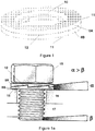
- Fig. 1 - 3 discloses prior art of locking washers 8A, 8B used in pair.
- the locking washers general comprises engagement means in the form of teeth 11 on one side and engagement means in the form of cams 12 on the other side.
- the locking washers 8A, 8B are intended to be used in a pair and are always exact copies of each other. The only difference between washer 8A and 8B is that they are turned opposite to each other.
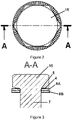
- Fig. 1 discloses a prior art locking washer 8A, 8B having ha chamfer 10.
- This chamfer 10 has been introduced to adapt the locking washer to a screw having a radius 5 or a chamfer with two radiuses 5', 5a, 5b, see figures 7 and 8 , for explanation of how the screw 15 can be constituted.
- the washers in Fig. 1 has this constitution with chamfers 10 such that the washers 8A, 8B can fit on a screw having the radius 5 or chamfer 5' with two radiuses 5a, 5B and thus the teeth of washer 8A can be engage with the head of the screw as seen in Fig. 1a .
- Fig. 1a discloses the function of the teeth 11 and the cams 12.
- the teeth 11 engage with the screws head and with the work piece to be attached 16.
- the screw 15 has a thread that engages with a threaded element 17.
- the pitch angle ⁇ of the thread is always smaller than the wedge angle ⁇ of the cams of the locking washers. With this configuration the screw joint is locked firmly.
- the teeth 11 can have any general configuration in order to be able to engage.
- the shown configuration is a leaning pyramidal shape where the leaning teeth 11 engage with their steeper side to the head of the screw 15 or work piece 16.
- Other configurations of the teeth 11 are thinkable.
- the teeth 11 could have configuration with a homogenous pyramidal shape.
- the teeth 11 can also have a trapezoidal shape. It is important that the teeth 11 have a hardness that is superior the screw head and the work piece 16. The reason for this is that the teeth 11 must be able to engage with the material they are positioned adjacent, in order to achieve a locking function.
- the teeth could be flattened by the momentum when tightening the screw joint, or slide on a harder adjacent surface.
- the locking washer 8A is moved with the screw 15 when tightening the screw joint and the locking washer 8B is keep still on the work piece 16.
- the cams 12 can be described as wedges see Figure 2 as an example of this.
- the cams 12 have the ability to lock against each other's steep surface.
- the respective locking washer 8A, 8B can thus when being tightened to each other have their respective cams 12 positioned adjacent each other. Locking is achieved by the wedge shape of the cams 12.
- the teeth 11 of the locking washers engage with the screw's head and the element 16 that has been attached.
- the locking washer 8A is seeking to follow the motion in the turning direction of the screw 15 and the other washer 8B is seeking to be maintained in position by its respective teeth 11 engaged with the work piece 16.
- the cams 12 slide on each other thus seeking to extend the screw joint in the longitudinal direction of the screw 15, by means of the inclination, wedge angle ⁇ , of the cams surface when sliding in the untightening direction. This extension locks the screw joint and prevents the screw from untightening. Thus the cams 12 prevent the locking washers 8A, 8B from being moved in the untightening direction of the screw.
- teeth 11 and cams 12 can in genera be described in that the teeth are note designed to interact with another serrated surface, where as the cams 12 is intentionally intended to cooperate with each other on the respective locking washer. And the cams 12 should have a wedge angled of particular configuration as above and as seen in Figure 1a .
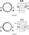
- the locking washer 9A and 9B has been dislocated to one side and thus the locking washers 9A, 9B is no longer centred on the screw.
- Fig. 3 , 4 and 5 explains explicitly the problem with the prior art.
- the locking washers 8A and 8B of Fig. 3 can crack or mal function due to the gap 4.
- Fig. 5 it is clear that the looking function of the locking washers 9A, 9B have a risk of not being centred with each other. This means that the cooperative locking of the locking washers 9A, 9B is jeopardized.
- the force distribution against the surface where the teeth 11 are to engage is also affected negatively, as it becomes unbalanced and more surface is provided on one lateral side of the locking washers 9A, 9B than the other side.
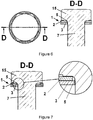
- Figure 6 discloses a locking washer assembly 1 according to the proposed solution to remove at least some of the drawbacks of the discussed prior art.
- the locking washer assembly comprises a first locking washer 2 and a second locking washer 3.
- the first locking washer 2 is intended to be positioned adjacent the screw head of a screw 15.
- the screw 15 as disclosed in Figure 6 has a radius between the head and the shank 7 of the screw.
- the first locking washer 2 has a through hole that is larger than the through hole of the second locking washer 3.
- the through hole diameter is essentially the same as the diameter of a circle that can be described as where the radius of the screw 15 joins the flat surface of the underside of the screw 15 that begins when the radius 5 ends.
- This diameter of the first locking washer 2 through hole sets the minimum diameter of the through hole.
- a larger through hole of locking washer 2 is thinkable, but the through hole should not be extensively larger than the minimum diameter as this both will diminish the surface of teeth 11 that can engage with the surface of the screw 15.
- a certain contact surface of the locking washer 2 against the screw head is necessary. A too large through hole will diminish the contact surface and also there is risk of deformation of the screw's head and compression set of the screw's head.
- the through hole has a border that is chamfered according to Figure 9 .
- the chamfer 2'a is adapted such that the diameter of the through hole has a minimum diameter that is larger than the diameter of the through hole of the second locking washer 3.
- the chamfer 2'a makes the through hole border to have the constitution of a truncated cone.
- the second locking washer 3 is of standard configuration in line with locking washer 8B, wherein it has a diameter of the through hole that is slightly larger than the outer diameter of the screw shank 7. Slightly in this context means that the through hole of locking washer 3 is larger than the shank 7 of the screw 15 but not so large that no guidance of the locking washer 3 to the screw shank 7 is achieved. In other words the second locking washer 3 should essentially not be able to be put of centre on the screw shank 7.
- the guiding of the second locking washer 3 should be understood to mean that the through hole of the diameter of the second locking washer 3 is only slightly larger than the shank of the screw shank 7, such that the washer gets guidance from the shank when introduced on this.
- the through hole of washer 3 has a diameter that means that if the washer is introduce wrongly i.e. closest to the head of a screw 15 having a radius 5 or a camfer 5' having two radiuses 5a, 5b, the second locking washer 3 will, when being parallel, with the underside of the screw head, form a gap as seen in figure 3 .
- the locking washer assembly 1 as discussed above provides for a very good engagement of the teeth 11 of the first locking washer 2 to the screw 15. And also by the engagement of the cams 12 between the first locking washer 2 and the second locking washer 3 the first locking washer 2 is prevented from being dislocated in the lateral direction of the screw 15. Thus the second locking washer 3 holds the first locking washer 2 by means of the smaller inner diameter of the through hole 3 against the shank 7 of the screw 15.
- the locking washer assembly 1 is possible to use with several different configurations of screws 15.
- the transition between the head of the screw 15 can have a radius 5 as shown in Figure 7 .
- the transition between the head of the screw 15 can also be in the form of a chamfer 5' with two radiuses 5a, 5b as seen in Figure 8 .
- the locking washer assembly 1' of figure 9 is used with a screw 15' according to figure 8 .
- a particularly well functioning locking function is achieved, where the wedged cam surface of locking washer 2' can be made slightly larger than for a first locking washer 2 with straight inner border of the through hole.
- locking washer assembly 1 can always be replace by locking washer assembly 1'.
- the first and the second locking washers 2, 2', 3 are joined to each other such that the locking washer assembly 1, 1' can be handled easily.
- the locking washer assembly 1; 1' is called a locking washer unit.
- the locking washers 2, 2', 3 are preferably joine to each other by means of a glue.
- the glue should allow relative movement between the first and the second locking washer 2, 2', 3. Glues that have this ability are for example various melt glues.
- the locking washers 2, 2' 3 should be able to be handled as an locking washer assembly 1, 1' by means of the glue.
- the locking washer assembly 1, 1' is preinstalled on a screw 15, 15', and 15" into an attachment assembly.
- the locking washer assembly can be put onto a non threaded screw 15, 15', 15" and thereafter a thread is rolled an a part of the screw 15, 15', 15", this augmenting the diameter and preventing the locking washer assembly 1, 1' from being detached from the screw.
Landscapes
- Engineering & Computer Science (AREA)
- General Engineering & Computer Science (AREA)
- Mechanical Engineering (AREA)
- Bolts, Nuts, And Washers (AREA)
Claims (12)
- Sicherungsscheibenanordnung (1; 1'), die zur Verwendung mit einer Schraube vorgesehen ist, wobei die Sicherungsscheibenanordnung eine erste Sicherungsscheibe (2, 2') und eine zweite Sicherungsscheibe (3) umfasst, wobei die erste (2; 2') und zweite Sicherungsscheibe (3) Zähne (11) zum Eingriff eines mittels einer Verschraubung zu befestigenden Elements (16, 17) umfassen, und die erste und zweite Sicherungsscheibe (1; 1') ferner Mittel (12) zum Eingriff miteinander umfassen, wobei die erste Sicherungsscheibe (2; 2') ein zentrales Durchgangsloch umfasst, das größer als das Mittelloch der zweiten Sicherungsscheibe (3) ist, dadurch gekennzeichnet, dass die zweite Sicherungsscheibe (3) einen Durchmesser ihres mittigen Durchgangslochs aufweist, der die Zähne der zweiten Sicherungsscheibe (3) verhindert, mit einem Schraubenkopf in Eingriff zu gelangen, der eine Abschrägung oder einen Radius in dem Übergang zwischen dem Schraubenkopf und dem Schaft (7) der Schraube (15, 15', 15") aufweist, mit der sie zur Verwendung vorgesehen ist, wobei das Durchgangsloch einen Durchmesser aufweist, dass, wenn die Sicherungsscheibe dem Schraubenkopf mit dem Radius (5) oder der Abschrägung (5') mit zwei Radien (5a, 5b) am nächsten eingeführt wird, die zweite Sicherungsscheibe dann, wenn sie zur Unterseite des Schraubenkopfs parallel ist, einen Spalt (4) bilden wird, wobei die erste (2; 2') und die zweite Sicherungsscheibe (3) des Typs einer Nockenverriegelung ist, die erste Sicherungsscheibe (2; 2") einen Durchmesser ihres zentralen Durchgangslochs aufweist, der ermöglicht, dass die Zähne (11) der ersten Sicherungsscheibe mit einer Oberfläche des Schraubenkopfs in Eingriff gelangen können, wobei dieser Eingriff möglich ist, wenn die erste Sicherungsscheibe (2; 2') gegen den Schraubenkopf nach oben gedrückt wird.
- Sicherungsscheibenanordnung (1; 1') nach Anspruch 1, wobei das Mittelloch der ersten Sicherungsscheibe (2, 2') mit einem Durchmesser ausgelegt ist, der es der ersten Sicherungsscheibe (2, 2') ermöglicht, seitlich beweglich zu sein, wenn sie sich auf einem Schraubenschaft (7) im Eingriff befindet, auf welchem es vorgesehen ist, dass die erste Sicherungsscheibe (2; 2') verwendet werden soll, so dass die erste Sicherungsscheibe (2, 2') derart bewegt werden kann, dass sie seitlich exzentrisch sichtbar ist.
- Sicherungsscheibenanordnung (1; 1') nach Anspruch 1 oder 2, wobei das Mittelloch der zweiten Sicherungsscheibe (3) eine Größe aufweist, die leicht größer ist als der Durchmesser eines Schraubenschafts (7) ist, auf welchem es vorgesehen ist, dass sie verwendet werden soll, jedoch nicht größer ist als für das Ermöglichen einer Führung der zweiten Sicherungsscheibe (3) auf dem Schraubenschaft (7).
- Sicherungsscheibenanordnung (1; 1') nach einem der vorhergehenden Ansprüche, wobei die erste Sicherungsscheibe (2; 2') und die zweite Sicherungsscheibe (3) zu einer Sicherungsscheibeneinheit vormontiert sind.
- Sicherungsscheibenanordnung (1; 1') nach Anspruch 4, wobei die erste und die zweite Sicherungsscheibe (2; 2'; 3) mittels eines Klebstoffes vormontiert sind.
- Sicherungsscheibenanordnung (1; 1') nach einem der vorhergehenden Ansprüche, wobei die Zähne zum Eingriff des zu befestigenden Elements in Form von radial sich erstreckenden Zähnen (11) gebildet sind.
- Sicherungsscheibenanordnung (1; 1') nach einem der vorhergehenden Ansprüche, wobei die Mittel zum Eingriff der ersten und der zweiten Sicherungsscheibe (2; 2'; 3) ineinander in Form von radial sich erstreckenden Nocken (12) gebildet sind.
- Sicherungsscheibenanordnung (1; 1') nach Anspruch 7, wobei die Nocken (12) einen Keilwinkel α aufweisen, der dazu angepasst ist, größer als der entsprechende Neigungswinkel β für ein Gewinde einer Schraube (15, 15', 15") zu sein, mit der sie zur Verwendung vorgesehen sind.
- Sicherungsscheibenanordnung (1') nach einem der vorhergehenden Ansprüche, wobei die erste Sicherungsscheibe (2') eine Abschrägung (2'a) am Rand des mittigen Durchgangslochs aufweist.
- Befestigungsanordnung umfassend eine Befestigungsmontageschraube (15.15', 15"), die zur Verwendung mit einer Sicherungsscheibenanordnung vorgesehen ist, und eine Sicherungsscheibenanordnung (1; 1') nach einem der Ansprüche 1 - 9.
- Befestigungsanordnung umfassend eine Befestigungsmontageschraube (15, 15', 15"), die einen nicht scharfen Übergang von einem Kopf der Befestigungsmontageschraube zu einem Schaft der Befestigungsmontageschraube aufweist, und eine Sicherungsscheibenanordnung nach einem der Ansprüche 1-9.
- Befestigungsanordnung nach Anspruch 11, wobei das mittige Durchgangsloch der ersten Sicherungsscheibe einen Durchmesser aufweist, der im Wesentlichen dem Durchmesser eines Kreises entspricht, der als die Stelle beschrieben werden kann, wo ein Radius zwischen dem Kopf der Befestigungsmontageschraube und dem Schaft der Befestigungsmontageschraube die flache Oberfläche der Unterseite des Befestigungsmontageschraubenkopfs angrenzt, beginnend, wenn der Radius endet.
Priority Applications (1)
| Application Number | Priority Date | Filing Date | Title |
|---|---|---|---|
| PL14756437T PL2962001T3 (pl) | 2013-02-28 | 2014-02-28 | Mocowanie podkładki zabezpieczającej |
Applications Claiming Priority (2)
| Application Number | Priority Date | Filing Date | Title |
|---|---|---|---|
| SE1350242A SE537673C2 (sv) | 2013-02-28 | 2013-02-28 | Låsbrickanordning |
| PCT/SE2014/050246 WO2014133446A1 (en) | 2013-02-28 | 2014-02-28 | Locking washer assembly |
Publications (3)
| Publication Number | Publication Date |
|---|---|
| EP2962001A1 EP2962001A1 (de) | 2016-01-06 |
| EP2962001A4 EP2962001A4 (de) | 2016-10-12 |
| EP2962001B1 true EP2962001B1 (de) | 2021-04-14 |
Family
ID=51428587
Family Applications (1)
| Application Number | Title | Priority Date | Filing Date |
|---|---|---|---|
| EP14756437.1A Active EP2962001B1 (de) | 2013-02-28 | 2014-02-28 | Sicherungsscheibenanordnung |
Country Status (9)
| Country | Link |
|---|---|
| US (1) | US9732782B2 (de) |
| EP (1) | EP2962001B1 (de) |
| JP (1) | JP6530320B2 (de) |
| KR (1) | KR102232065B1 (de) |
| CN (1) | CN105074235B (de) |
| PL (1) | PL2962001T3 (de) |
| RU (1) | RU2640465C2 (de) |
| SE (1) | SE537673C2 (de) |
| WO (1) | WO2014133446A1 (de) |
Families Citing this family (23)
| Publication number | Priority date | Publication date | Assignee | Title |
|---|---|---|---|---|
| JP6377559B2 (ja) * | 2015-02-20 | 2018-08-22 | 株式会社マルナカ | 座金付き螺子類 |
| GB201510008D0 (en) * | 2015-06-09 | 2015-07-22 | Completion Products Ltd | Clamp and method of applying a clamp |
| JP6934161B2 (ja) * | 2017-02-24 | 2021-09-15 | ボルトエンジニア株式会社 | 締結構造 |
| PL3601813T3 (pl) * | 2017-03-24 | 2024-12-09 | Ejot Se & Co. Kg | Tarcza mocująca i sposób wstępnego mocowania elementu mocującego oraz usuwania folii ochronnej |
| DE102017131005A1 (de) * | 2017-12-21 | 2019-06-27 | Hartmut Flaig | Gewindeelement sowie damit herstellbare Verbindung |
| TWM562350U (zh) * | 2018-01-30 | 2018-06-21 | Unitech Products Corp | 兩件式防鬆螺帽組件 |
| TWM562351U (zh) * | 2018-01-30 | 2018-06-21 | Unitech Products Corp | 兩件式防鬆螺絲組件 |
| US11867222B2 (en) * | 2018-06-11 | 2024-01-09 | John Eric Chapman | Hybrid washer |
| JP2020143781A (ja) * | 2019-02-28 | 2020-09-10 | ボルトエンジニア株式会社 | ロックワッシャ、締結構造及びその締結構造の締結を解除する方法 |
| WO2020174652A1 (ja) * | 2019-02-28 | 2020-09-03 | ボルトエンジニア株式会社 | ロックワッシャ、締結構造及びその締結構造の締結を解除する方法 |
| US11396902B2 (en) * | 2019-06-20 | 2022-07-26 | The Reaction Washer Company, Llc | Engaging washers |
| US11242884B2 (en) * | 2019-09-18 | 2022-02-08 | Laitram, L.L.C. | Sealing wedge-lock washer and fastening system |
| US11525384B2 (en) * | 2020-02-03 | 2022-12-13 | Fca Us Llc | High temperature resistant low friction washer and assembly |
| TWI742612B (zh) * | 2020-04-13 | 2021-10-11 | 中國氣動工業股份有限公司 | 螺栓夾緊力感應墊圈 |
| CN113550966A (zh) * | 2020-04-24 | 2021-10-26 | 中国气动工业股份有限公司 | 螺栓夹紧力感应垫圈 |
| WO2021224979A1 (ja) * | 2020-05-08 | 2021-11-11 | ボルトエンジニア株式会社 | ワッシャ |
| US11444002B2 (en) * | 2020-07-29 | 2022-09-13 | Taiwan Semiconductor Manufacturing Company, Ltd. | Package structure |
| US11534894B2 (en) | 2020-11-17 | 2022-12-27 | The Reaction Washer Company Llc | Socket devices and methods of use |
| KR102507463B1 (ko) * | 2021-03-23 | 2023-03-09 | 주식회사 엔케이 | 회전방지형 압력용기 |
| US20230087369A1 (en) | 2021-09-21 | 2023-03-23 | Caterpillar Inc. | Track shoe or track bolt with increased surface roughness |
| CN114909385B (zh) * | 2022-05-13 | 2023-03-17 | 中国人民解放军总医院第四医学中心 | 一种避免松动的螺钉预紧系统 |
| DE102023107759A1 (de) * | 2023-03-28 | 2024-10-02 | Nord-Lock International Ab | Anordnung zur Verbindung von Bauteilen |
| US12385514B1 (en) * | 2024-02-09 | 2025-08-12 | Heico Befestigungstechnik Gmbh | Wedge lock washer pair and tensioning arrangement with such wedge lock washer pair |
Family Cites Families (15)
| Publication number | Priority date | Publication date | Assignee | Title |
|---|---|---|---|---|
| GB792215A (en) * | 1956-07-09 | 1958-03-19 | John Ryan Mckee Jr | Improvements relating to composite washers |
| GB1109240A (en) * | 1965-06-26 | 1968-04-10 | Girling Ltd | Improvements in and relating to tab washers |
| JPS5259868U (de) * | 1975-10-29 | 1977-04-30 | ||
| JPS5820724U (ja) * | 1981-08-03 | 1983-02-08 | セントラル通商株式会社 | ワツシヤ |
| RU2008534C1 (ru) * | 1991-05-07 | 1994-02-28 | Войсковая Часть 25840 | Устройство для фиксации резьбового стержня |
| CN2101133U (zh) | 1991-09-06 | 1992-04-08 | 刘永熙 | 轴向锁紧式防松防盗螺帽 |
| US5203656A (en) * | 1991-09-19 | 1993-04-20 | Hong Kong Disc Lock Company, Limited | Self-centering, self-tightening fastener |
| US5688091A (en) * | 1995-09-15 | 1997-11-18 | Hong-Kong Disc Lock Company, Ltd. | Self-locking fastener with captive washer |
| WO2000077410A1 (fr) * | 1999-06-14 | 2000-12-21 | Masaki Yamazaki | Dispositif de visserie |
| US7168902B2 (en) | 2002-10-09 | 2007-01-30 | Terry Sydney L | Wedge cam lock washer for threaded fasteners |
| AT414346B (de) * | 2003-09-05 | 2013-10-15 | Best On Bolt Gmbh | Sicherungselement zur sicherung von schraubenelementen |
| DE102005054471A1 (de) * | 2005-11-15 | 2007-05-24 | Thyssenkrupp Bilstein Suspension Gmbh | Schraubensicherung |
| SE531379C2 (sv) | 2006-06-08 | 2009-03-17 | Nord Lock Ab | Metod för att härda och belägga stålbrickor för låsning samt stållåsbricka |
| SE532106C2 (sv) * | 2006-09-01 | 2009-10-27 | Nord Lock Ab | Låssystem innefattande ett fästelement och en låsbrickenhet |
| US8079795B2 (en) * | 2009-03-23 | 2011-12-20 | Junkers John K | Washer for tightening and loosening threaded connectors |
-
2013
- 2013-02-28 SE SE1350242A patent/SE537673C2/sv unknown
-
2014
- 2014-02-28 PL PL14756437T patent/PL2962001T3/pl unknown
- 2014-02-28 US US14/771,470 patent/US9732782B2/en active Active
- 2014-02-28 KR KR1020157026943A patent/KR102232065B1/ko active Active
- 2014-02-28 RU RU2015141067A patent/RU2640465C2/ru active
- 2014-02-28 CN CN201480010691.1A patent/CN105074235B/zh active Active
- 2014-02-28 WO PCT/SE2014/050246 patent/WO2014133446A1/en not_active Ceased
- 2014-02-28 JP JP2015560140A patent/JP6530320B2/ja active Active
- 2014-02-28 EP EP14756437.1A patent/EP2962001B1/de active Active
Non-Patent Citations (1)
| Title |
|---|
| None * |
Also Published As
| Publication number | Publication date |
|---|---|
| RU2640465C2 (ru) | 2018-01-09 |
| US20160003287A1 (en) | 2016-01-07 |
| SE537673C2 (sv) | 2015-09-29 |
| RU2015141067A (ru) | 2017-04-03 |
| KR102232065B1 (ko) | 2021-03-24 |
| SE1350242A1 (sv) | 2014-08-29 |
| JP2016509179A (ja) | 2016-03-24 |
| CN105074235B (zh) | 2017-06-09 |
| WO2014133446A1 (en) | 2014-09-04 |
| EP2962001A4 (de) | 2016-10-12 |
| EP2962001A1 (de) | 2016-01-06 |
| US9732782B2 (en) | 2017-08-15 |
| KR20150119475A (ko) | 2015-10-23 |
| CN105074235A (zh) | 2015-11-18 |
| JP6530320B2 (ja) | 2019-06-12 |
| PL2962001T3 (pl) | 2021-11-02 |
Similar Documents
| Publication | Publication Date | Title |
|---|---|---|
| EP2962001B1 (de) | Sicherungsscheibenanordnung | |
| EP3017204B1 (de) | Befestigungselement und befestigungseinheit | |
| US9011060B2 (en) | No flange damage wedge lock washers | |
| US9121431B2 (en) | Cage nut | |
| EP2431619B1 (de) | System für die lösbare verbindung dicker teile | |
| US20050079028A1 (en) | Fastener | |
| US1969796A (en) | Separable fastener and installation thereof | |
| EP0172739A1 (de) | Befestigungsvorrichtung | |
| US8966874B2 (en) | Shackle assembly with locking pin | |
| US20120070245A1 (en) | Fastener | |
| EP2478230B1 (de) | System und verfahren für die starre verbindung von tafeln | |
| GB2343228A (en) | A fastener having a nut, cage and washer with cam surfaces | |
| JP5083511B2 (ja) | 締結・固定構造 | |
| CN217783989U (zh) | 紧固组件 | |
| US20100034577A1 (en) | Mounting arrangement | |
| KR20170002262A (ko) | 고정안정성 증대용 결합면을 갖는 고정구 세트 | |
| CA1283567C (en) | Fastening device | |
| JP2015017659A (ja) | ボルト・ナットの弛み止め構造 | |
| WO1997002927A1 (de) | Schraubendreherbit | |
| HK1138345B (en) | Zero-clearance bolted joint |
Legal Events
| Date | Code | Title | Description |
|---|---|---|---|
| PUAI | Public reference made under article 153(3) epc to a published international application that has entered the european phase |
Free format text: ORIGINAL CODE: 0009012 |
|
| 17P | Request for examination filed |
Effective date: 20150918 |
|
| AK | Designated contracting states |
Kind code of ref document: A1 Designated state(s): AL AT BE BG CH CY CZ DE DK EE ES FI FR GB GR HR HU IE IS IT LI LT LU LV MC MK MT NL NO PL PT RO RS SE SI SK SM TR |
|
| AX | Request for extension of the european patent |
Extension state: BA ME |
|
| DAX | Request for extension of the european patent (deleted) | ||
| A4 | Supplementary search report drawn up and despatched |
Effective date: 20160909 |
|
| RIC1 | Information provided on ipc code assigned before grant |
Ipc: F16B 39/24 20060101AFI20160905BHEP Ipc: F16B 43/00 20060101ALI20160905BHEP Ipc: F16B 39/282 20060101ALI20160905BHEP |
|
| STAA | Information on the status of an ep patent application or granted ep patent |
Free format text: STATUS: EXAMINATION IS IN PROGRESS |
|
| 17Q | First examination report despatched |
Effective date: 20180921 |
|
| GRAP | Despatch of communication of intention to grant a patent |
Free format text: ORIGINAL CODE: EPIDOSNIGR1 |
|
| STAA | Information on the status of an ep patent application or granted ep patent |
Free format text: STATUS: GRANT OF PATENT IS INTENDED |
|
| INTG | Intention to grant announced |
Effective date: 20201110 |
|
| GRAS | Grant fee paid |
Free format text: ORIGINAL CODE: EPIDOSNIGR3 |
|
| GRAA | (expected) grant |
Free format text: ORIGINAL CODE: 0009210 |
|
| STAA | Information on the status of an ep patent application or granted ep patent |
Free format text: STATUS: THE PATENT HAS BEEN GRANTED |
|
| AK | Designated contracting states |
Kind code of ref document: B1 Designated state(s): AL AT BE BG CH CY CZ DE DK EE ES FI FR GB GR HR HU IE IS IT LI LT LU LV MC MK MT NL NO PL PT RO RS SE SI SK SM TR |
|
| REG | Reference to a national code |
Ref country code: GB Ref legal event code: FG4D |
|
| REG | Reference to a national code |
Ref country code: CH Ref legal event code: EP |
|
| REG | Reference to a national code |
Ref country code: DE Ref legal event code: R096 Ref document number: 602014076581 Country of ref document: DE |
|
| REG | Reference to a national code |
Ref country code: IE Ref legal event code: FG4D |
|
| REG | Reference to a national code |
Ref country code: AT Ref legal event code: REF Ref document number: 1382645 Country of ref document: AT Kind code of ref document: T Effective date: 20210515 |
|
| REG | Reference to a national code |
Ref country code: SE Ref legal event code: TRGR |
|
| REG | Reference to a national code |
Ref country code: LT Ref legal event code: MG9D |
|
| REG | Reference to a national code |
Ref country code: AT Ref legal event code: MK05 Ref document number: 1382645 Country of ref document: AT Kind code of ref document: T Effective date: 20210414 |
|
| REG | Reference to a national code |
Ref country code: NL Ref legal event code: MP Effective date: 20210414 |
|
| PG25 | Lapsed in a contracting state [announced via postgrant information from national office to epo] |
Ref country code: LT Free format text: LAPSE BECAUSE OF FAILURE TO SUBMIT A TRANSLATION OF THE DESCRIPTION OR TO PAY THE FEE WITHIN THE PRESCRIBED TIME-LIMIT Effective date: 20210414 Ref country code: NL Free format text: LAPSE BECAUSE OF FAILURE TO SUBMIT A TRANSLATION OF THE DESCRIPTION OR TO PAY THE FEE WITHIN THE PRESCRIBED TIME-LIMIT Effective date: 20210414 Ref country code: FI Free format text: LAPSE BECAUSE OF FAILURE TO SUBMIT A TRANSLATION OF THE DESCRIPTION OR TO PAY THE FEE WITHIN THE PRESCRIBED TIME-LIMIT Effective date: 20210414 Ref country code: BG Free format text: LAPSE BECAUSE OF FAILURE TO SUBMIT A TRANSLATION OF THE DESCRIPTION OR TO PAY THE FEE WITHIN THE PRESCRIBED TIME-LIMIT Effective date: 20210714 Ref country code: AT Free format text: LAPSE BECAUSE OF FAILURE TO SUBMIT A TRANSLATION OF THE DESCRIPTION OR TO PAY THE FEE WITHIN THE PRESCRIBED TIME-LIMIT Effective date: 20210414 Ref country code: HR Free format text: LAPSE BECAUSE OF FAILURE TO SUBMIT A TRANSLATION OF THE DESCRIPTION OR TO PAY THE FEE WITHIN THE PRESCRIBED TIME-LIMIT Effective date: 20210414 |
|
| PG25 | Lapsed in a contracting state [announced via postgrant information from national office to epo] |
Ref country code: RS Free format text: LAPSE BECAUSE OF FAILURE TO SUBMIT A TRANSLATION OF THE DESCRIPTION OR TO PAY THE FEE WITHIN THE PRESCRIBED TIME-LIMIT Effective date: 20210414 Ref country code: ES Free format text: LAPSE BECAUSE OF FAILURE TO SUBMIT A TRANSLATION OF THE DESCRIPTION OR TO PAY THE FEE WITHIN THE PRESCRIBED TIME-LIMIT Effective date: 20210414 Ref country code: PT Free format text: LAPSE BECAUSE OF FAILURE TO SUBMIT A TRANSLATION OF THE DESCRIPTION OR TO PAY THE FEE WITHIN THE PRESCRIBED TIME-LIMIT Effective date: 20210816 Ref country code: NO Free format text: LAPSE BECAUSE OF FAILURE TO SUBMIT A TRANSLATION OF THE DESCRIPTION OR TO PAY THE FEE WITHIN THE PRESCRIBED TIME-LIMIT Effective date: 20210714 Ref country code: IS Free format text: LAPSE BECAUSE OF FAILURE TO SUBMIT A TRANSLATION OF THE DESCRIPTION OR TO PAY THE FEE WITHIN THE PRESCRIBED TIME-LIMIT Effective date: 20210814 Ref country code: LV Free format text: LAPSE BECAUSE OF FAILURE TO SUBMIT A TRANSLATION OF THE DESCRIPTION OR TO PAY THE FEE WITHIN THE PRESCRIBED TIME-LIMIT Effective date: 20210414 Ref country code: GR Free format text: LAPSE BECAUSE OF FAILURE TO SUBMIT A TRANSLATION OF THE DESCRIPTION OR TO PAY THE FEE WITHIN THE PRESCRIBED TIME-LIMIT Effective date: 20210715 |
|
| REG | Reference to a national code |
Ref country code: DE Ref legal event code: R097 Ref document number: 602014076581 Country of ref document: DE |
|
| PG25 | Lapsed in a contracting state [announced via postgrant information from national office to epo] |
Ref country code: RO Free format text: LAPSE BECAUSE OF FAILURE TO SUBMIT A TRANSLATION OF THE DESCRIPTION OR TO PAY THE FEE WITHIN THE PRESCRIBED TIME-LIMIT Effective date: 20210414 Ref country code: SM Free format text: LAPSE BECAUSE OF FAILURE TO SUBMIT A TRANSLATION OF THE DESCRIPTION OR TO PAY THE FEE WITHIN THE PRESCRIBED TIME-LIMIT Effective date: 20210414 Ref country code: SK Free format text: LAPSE BECAUSE OF FAILURE TO SUBMIT A TRANSLATION OF THE DESCRIPTION OR TO PAY THE FEE WITHIN THE PRESCRIBED TIME-LIMIT Effective date: 20210414 Ref country code: EE Free format text: LAPSE BECAUSE OF FAILURE TO SUBMIT A TRANSLATION OF THE DESCRIPTION OR TO PAY THE FEE WITHIN THE PRESCRIBED TIME-LIMIT Effective date: 20210414 Ref country code: CZ Free format text: LAPSE BECAUSE OF FAILURE TO SUBMIT A TRANSLATION OF THE DESCRIPTION OR TO PAY THE FEE WITHIN THE PRESCRIBED TIME-LIMIT Effective date: 20210414 Ref country code: DK Free format text: LAPSE BECAUSE OF FAILURE TO SUBMIT A TRANSLATION OF THE DESCRIPTION OR TO PAY THE FEE WITHIN THE PRESCRIBED TIME-LIMIT Effective date: 20210414 |
|
| PLBE | No opposition filed within time limit |
Free format text: ORIGINAL CODE: 0009261 |
|
| STAA | Information on the status of an ep patent application or granted ep patent |
Free format text: STATUS: NO OPPOSITION FILED WITHIN TIME LIMIT |
|
| 26N | No opposition filed |
Effective date: 20220117 |
|
| PG25 | Lapsed in a contracting state [announced via postgrant information from national office to epo] |
Ref country code: IS Free format text: LAPSE BECAUSE OF FAILURE TO SUBMIT A TRANSLATION OF THE DESCRIPTION OR TO PAY THE FEE WITHIN THE PRESCRIBED TIME-LIMIT Effective date: 20210814 Ref country code: AL Free format text: LAPSE BECAUSE OF FAILURE TO SUBMIT A TRANSLATION OF THE DESCRIPTION OR TO PAY THE FEE WITHIN THE PRESCRIBED TIME-LIMIT Effective date: 20210414 |
|
| PG25 | Lapsed in a contracting state [announced via postgrant information from national office to epo] |
Ref country code: MC Free format text: LAPSE BECAUSE OF FAILURE TO SUBMIT A TRANSLATION OF THE DESCRIPTION OR TO PAY THE FEE WITHIN THE PRESCRIBED TIME-LIMIT Effective date: 20210414 |
|
| REG | Reference to a national code |
Ref country code: CH Ref legal event code: PL |
|
| REG | Reference to a national code |
Ref country code: BE Ref legal event code: MM Effective date: 20220228 |
|
| PG25 | Lapsed in a contracting state [announced via postgrant information from national office to epo] |
Ref country code: LU Free format text: LAPSE BECAUSE OF NON-PAYMENT OF DUE FEES Effective date: 20220228 |
|
| PG25 | Lapsed in a contracting state [announced via postgrant information from national office to epo] |
Ref country code: LI Free format text: LAPSE BECAUSE OF NON-PAYMENT OF DUE FEES Effective date: 20220228 Ref country code: IE Free format text: LAPSE BECAUSE OF NON-PAYMENT OF DUE FEES Effective date: 20220228 Ref country code: CH Free format text: LAPSE BECAUSE OF NON-PAYMENT OF DUE FEES Effective date: 20220228 |
|
| PG25 | Lapsed in a contracting state [announced via postgrant information from national office to epo] |
Ref country code: BE Free format text: LAPSE BECAUSE OF NON-PAYMENT OF DUE FEES Effective date: 20220228 |
|
| P01 | Opt-out of the competence of the unified patent court (upc) registered |
Effective date: 20230530 |
|
| PG25 | Lapsed in a contracting state [announced via postgrant information from national office to epo] |
Ref country code: HU Free format text: LAPSE BECAUSE OF FAILURE TO SUBMIT A TRANSLATION OF THE DESCRIPTION OR TO PAY THE FEE WITHIN THE PRESCRIBED TIME-LIMIT; INVALID AB INITIO Effective date: 20140228 |
|
| PG25 | Lapsed in a contracting state [announced via postgrant information from national office to epo] |
Ref country code: MK Free format text: LAPSE BECAUSE OF FAILURE TO SUBMIT A TRANSLATION OF THE DESCRIPTION OR TO PAY THE FEE WITHIN THE PRESCRIBED TIME-LIMIT Effective date: 20210414 Ref country code: CY Free format text: LAPSE BECAUSE OF FAILURE TO SUBMIT A TRANSLATION OF THE DESCRIPTION OR TO PAY THE FEE WITHIN THE PRESCRIBED TIME-LIMIT Effective date: 20210414 |
|
| PG25 | Lapsed in a contracting state [announced via postgrant information from national office to epo] |
Ref country code: MT Free format text: LAPSE BECAUSE OF FAILURE TO SUBMIT A TRANSLATION OF THE DESCRIPTION OR TO PAY THE FEE WITHIN THE PRESCRIBED TIME-LIMIT Effective date: 20210414 |
|
| PGFP | Annual fee paid to national office [announced via postgrant information from national office to epo] |
Ref country code: GB Payment date: 20251211 Year of fee payment: 13 |
|
| PGFP | Annual fee paid to national office [announced via postgrant information from national office to epo] |
Ref country code: FR Payment date: 20251209 Year of fee payment: 13 |
|
| PGFP | Annual fee paid to national office [announced via postgrant information from national office to epo] |
Ref country code: SE Payment date: 20251210 Year of fee payment: 13 |
|
| PGFP | Annual fee paid to national office [announced via postgrant information from national office to epo] |
Ref country code: DE Payment date: 20260113 Year of fee payment: 13 |
|
| PGFP | Annual fee paid to national office [announced via postgrant information from national office to epo] |
Ref country code: IT Payment date: 20260114 Year of fee payment: 13 |
|
| PGFP | Annual fee paid to national office [announced via postgrant information from national office to epo] |
Ref country code: TR Payment date: 20260116 Year of fee payment: 13 |
|
| PGFP | Annual fee paid to national office [announced via postgrant information from national office to epo] |
Ref country code: PL Payment date: 20260129 Year of fee payment: 13 |