EP2961997B1 - Trägerteil zum befestigen von länglichen gegenständen, klammerteil zum aufstecken auf eine trägerplatte und anordnung mit einem trägerteil und mit einem klammerteil - Google Patents
Trägerteil zum befestigen von länglichen gegenständen, klammerteil zum aufstecken auf eine trägerplatte und anordnung mit einem trägerteil und mit einem klammerteil Download PDFInfo
- Publication number
- EP2961997B1 EP2961997B1 EP14705367.2A EP14705367A EP2961997B1 EP 2961997 B1 EP2961997 B1 EP 2961997B1 EP 14705367 A EP14705367 A EP 14705367A EP 2961997 B1 EP2961997 B1 EP 2961997B1
- Authority
- EP
- European Patent Office
- Prior art keywords
- support
- attachment
- section
- assembly position
- recesses
- Prior art date
- Legal status (The legal status is an assumption and is not a legal conclusion. Google has not performed a legal analysis and makes no representation as to the accuracy of the status listed.)
- Active
Links
- 239000000463 material Substances 0.000 claims description 5
- 210000002105 tongue Anatomy 0.000 claims description 3
- 238000004804 winding Methods 0.000 description 5
- 230000007704 transition Effects 0.000 description 4
- 238000004873 anchoring Methods 0.000 description 2
- 210000000078 claw Anatomy 0.000 description 2
- 230000004048 modification Effects 0.000 description 2
- 238000012986 modification Methods 0.000 description 2
- 238000004891 communication Methods 0.000 description 1
- 230000001419 dependent effect Effects 0.000 description 1
- 238000006073 displacement reaction Methods 0.000 description 1
- 239000004744 fabric Substances 0.000 description 1
- 210000001061 forehead Anatomy 0.000 description 1
- 239000002184 metal Substances 0.000 description 1
Images


Classifications
-
- F—MECHANICAL ENGINEERING; LIGHTING; HEATING; WEAPONS; BLASTING
- F16—ENGINEERING ELEMENTS AND UNITS; GENERAL MEASURES FOR PRODUCING AND MAINTAINING EFFECTIVE FUNCTIONING OF MACHINES OR INSTALLATIONS; THERMAL INSULATION IN GENERAL
- F16L—PIPES; JOINTS OR FITTINGS FOR PIPES; SUPPORTS FOR PIPES, CABLES OR PROTECTIVE TUBING; MEANS FOR THERMAL INSULATION IN GENERAL
- F16L3/00—Supports for pipes, cables or protective tubing, e.g. hangers, holders, clamps, cleats, clips, brackets
- F16L3/24—Supports for pipes, cables or protective tubing, e.g. hangers, holders, clamps, cleats, clips, brackets with a special member for attachment to profiled girders
- F16L3/245—Supports for pipes, cables or protective tubing, e.g. hangers, holders, clamps, cleats, clips, brackets with a special member for attachment to profiled girders the special member embracing the entire profiled girder
-
- F—MECHANICAL ENGINEERING; LIGHTING; HEATING; WEAPONS; BLASTING
- F16—ENGINEERING ELEMENTS AND UNITS; GENERAL MEASURES FOR PRODUCING AND MAINTAINING EFFECTIVE FUNCTIONING OF MACHINES OR INSTALLATIONS; THERMAL INSULATION IN GENERAL
- F16L—PIPES; JOINTS OR FITTINGS FOR PIPES; SUPPORTS FOR PIPES, CABLES OR PROTECTIVE TUBING; MEANS FOR THERMAL INSULATION IN GENERAL
- F16L3/00—Supports for pipes, cables or protective tubing, e.g. hangers, holders, clamps, cleats, clips, brackets
- F16L3/24—Supports for pipes, cables or protective tubing, e.g. hangers, holders, clamps, cleats, clips, brackets with a special member for attachment to profiled girders
-
- F—MECHANICAL ENGINEERING; LIGHTING; HEATING; WEAPONS; BLASTING
- F16—ENGINEERING ELEMENTS AND UNITS; GENERAL MEASURES FOR PRODUCING AND MAINTAINING EFFECTIVE FUNCTIONING OF MACHINES OR INSTALLATIONS; THERMAL INSULATION IN GENERAL
- F16B—DEVICES FOR FASTENING OR SECURING CONSTRUCTIONAL ELEMENTS OR MACHINE PARTS TOGETHER, e.g. NAILS, BOLTS, CIRCLIPS, CLAMPS, CLIPS OR WEDGES; JOINTS OR JOINTING
- F16B2/00—Friction-grip releasable fastenings
- F16B2/20—Clips, i.e. with gripping action effected solely by the inherent resistance to deformation of the material of the fastening
- F16B2/22—Clips, i.e. with gripping action effected solely by the inherent resistance to deformation of the material of the fastening of resilient material, e.g. rubbery material
- F16B2/24—Clips, i.e. with gripping action effected solely by the inherent resistance to deformation of the material of the fastening of resilient material, e.g. rubbery material of metal
- F16B2/241—Clips, i.e. with gripping action effected solely by the inherent resistance to deformation of the material of the fastening of resilient material, e.g. rubbery material of metal of sheet metal
- F16B2/245—Clips, i.e. with gripping action effected solely by the inherent resistance to deformation of the material of the fastening of resilient material, e.g. rubbery material of metal of sheet metal external, i.e. with contracting action
Definitions
- the invention relates to a carrier part for fastening elongated objects according to the preamble of claim 1.
- the invention further relates to a clamp member for attachment to a support plate according to the preamble of claim 2.
- the invention further relates to an arrangement with a carrier part and with a clamp part.
- the prior art support member for securing elongate articles has an elongated carrier strip and an elongate attachment tab which is positionable with respect to the carrier strip in a pre-assembly position and in a final assembly position extending towards the carrier strip.
- the fastening tab is pivotally connected to the carrier strip, wherein the fastening tab is connected via a hinge with a hinge formed by a material thickness reduction with the carrier strip.
- a latching hook is formed, which engages behind the fastening tab in the final assembly position, wherein in the final assembly position, the fastening tab is spaced from the carrier strip.
- Such a clamp part is made FR 1 428 487 A known.
- the previously known clamp part for mounting on a support plate has a support section, via a support section opposite the support section and via a support section and the plant section connecting forehead section. Furthermore, mutually aligned mounting recesses are present, through which in an end mounting position of the clamp member, an elongated fastening tab can be pushed.
- Two attachment recesses are formed on opposite edge sides of the end portion, and two attachment recesses are formed on a dome portion formed on the support portion whose connection line is perpendicular to the end portion.
- a further clamp member for attachment to a carrier plate which has a support portion over a support portion opposite the support portion and a connecting the support portion and the abutment portion end portion.
- the previously known clamp part has an engagement structure formed on the contact section for receiving a threaded screw.
- the invention has for its object to provide a support member for fixing elongated objects, which is reliably connected in a simple manner with a clamp member.
- the invention is further based on the object of specifying a staple part of the type mentioned, which is characterized by a very simple handling when connecting a support member for fixing elongated objects to a support plate in different orientations.
- the first object is achieved with a carrier part with the characterizing features of claim 1.
- the second object is achieved according to the invention in a clamp part of the type mentioned above with the characterizing features of claim 2.
- the third object is finally achieved according to the invention in an arrangement with a support member and with a clamp member according to the invention with the features of claim 4.
- the clamp part according to the invention has a dome area with crossing connecting lines of the fastening recesses or transverse recesses, elongated fastening straps in various orientations can be very easily connected, which makes the clamp part usable in different fastening situations.
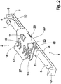
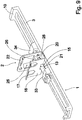
- Fig. 1 shows a perspective view of an embodiment of an inventive arrangement with an embodiment of a support member 1 according to the invention and with an embodiment of a clamp member 2 according to the invention.
- the carrier part 1 expediently made of a hard-elastic plastic material has an elongated narrow carrier strip 3 with a flat top facing the viewer in the illustration, which is formed with a central center section 4 and two side sections 5, 6 lying on one side of the center section 4 is.
- a side section 5 facing away from the middle section 4
- two latching hooks 7, 8 opposite each other in the transverse direction are integrally formed on one underside of the upper side of the carrier strip 3, locking lugs 9 formed on the latching hooks 7, 8 facing each other.
- an edge web 10 is formed, which extends away from the carrier strip 3 in the same direction as the latching hooks 7, 8.
- FIG. 1 the illustration according to Fig. 1 can be seen that in the transition region between the middle portion 4 and the latching hooks 7, 8 bearing side portion 5 on the mounting tab 13 side facing the carrier strip 3 edge side stops 14 are formed, extending in the same direction as the latching hooks 7, 8 and Edge portion 10 extend beyond the bottom and on the one hand stabilize the fastening tab 13 laterally and on the other limit between the joint socket 11 and the side stops 14 a receiving space 15, whose extension in the longitudinal direction of the center section 4 corresponds.
- Fig. 1 has an abutment portion 16 of rectangular base surface, of which an end portion 17 is inclined at a free edge side.
- the clamp member 2 is further formed with two claws 18, 19, which are integrally formed on the end portion 17 and in the plane of the end portion 17 lying away from the end portion 17 in the direction of the abutment portion 16 extend.
- the abutment portion 16 On the side facing away from the end portion 17, the abutment portion 16 is in communication with a front portion 20 which is aligned substantially at right angles to the abutment portion 16. In the transition region between the contact portion 16 and the end portion 20 a foot-side front recess 21 is formed centrally as a mounting recess.
- the support section 22 is formed in its center region on its side facing away from the contact section 16 with a raised dome region 23, the projection of which is preferably arranged over the edge regions of the support section 22 to avoid forced deformations of the support part 1, that the free ends of the latching hooks 7, 8 and the free end of the edge web 10 of the support part 1 at most extend to the underside of the support section 22 facing the contact section 16.
- the dome region 23 has, as further fastening recesses, two mutually opposite transverse recesses 24, 25, whose connecting line runs parallel to the end section 20, and has longitudinal recesses 26, 27 offset by 90 degrees from the transverse recesses 24, 25 as further fastening recesses, their connecting line is aligned at right angles to the end portion 20.
- the fastening strap 13 of the carrier part 1 extends through the transverse recesses 24, 25, the cover section of the dome region 23 facing away from the rest section 22 being arranged in the receiving space 15.
- the inside width of the receiving space 15 in the longitudinal direction of the carrier strip 3 is dimensioned such that the clamp part 2 in the arrangement according to Fig. 1 is displaceable over a certain displacement between the hinge base 11 and the side stops 14.
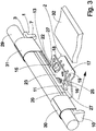
- Fig. 2 shows the exemplary arrangement according to Fig. 1 in a perspective view overlooking the latching hooks 7, 8 and the edge web 10 supporting bottom of the support member 1.
- Fig. 2 is clearly seen that both formed on the latching hooks 7, 8 locking lugs 9 in the in Fig. 2 illustrated final assembly position of the support member 1, the hinge socket 11 facing away from the free end of the fastening tab 13 engage behind in a not shown, opposite the final assembly position away from the carrier strip 3 angled pre-assembly position of the fastening tab 13, the clamp member 2 has been pushed onto the mounting bracket 13.
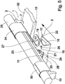
- Fig. 3 shows in a perspective view of the exemplary arrangement of a support member 1 and a clamp member 2 according to Fig. 1 respectively Fig. 2 and an elongated cable harness 29 as an example of an elongated object which is placed on the top of the carrier strip 3 facing away from the latching hooks 7, 8 and the edge web 10 and with arranged in the region of the side sections 5, 6 winding bands 30, 31 in the form of, for example Cloth straps or Velcro straps is attached to the carrier strip 3.
- a support plate 32 directly shown with the moving of the arrangement of carrier part 1 and clamp member 2 with attached thereto cable harness 29 in the direction of an edge side of the support plate 32, the clamp part 2 of the end portion 17 side facing the support plate 32 is connectable.
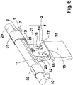
- Fig. 4 shows in a sectional view of the exemplary arrangement of carrier part 1 and clip part 2 according to Fig. 1 and Fig. 2 with attached cable harness 29 according to Fig. 3 in the plugged onto the support plate 32 position.
- the representation according to Fig. 4 can be clearly seen that the claw tongues 18, 19 with the support plate 32 are engaged and prevent unintentional removal or release of the arrangement of carrier part 1 and clamp part 2 of the support plate 32 except for very high withdrawal forces.
- the illustration according to Fig. 4 see that the latching hooks 7, 8 and the in Fig. 4 not visible edge web 10 on the side facing away from the contact portion 16 of the support plate 32 and thus stabilize the carrier strip 3.
- Fig. 5 shows in a perspective view of the embodiments of carrier part 1 and clamp part 2 according to Fig. 1 and Fig. 2 in a further exemplary arrangement, in which the fastening tab 13 now extends through the longitudinal recesses 26, 27.
- the fastening tab 13 now extends through the longitudinal recesses 26, 27.
- Fig. 6 shows in a further perspective view of the embodiments of carrier part 1 and clamp part 2, wherein in the exemplary Anodnung according to Fig. 6 the fastening tab 13 engages behind the end portion 20 of the clamp member 2 and the end portion 20 is arranged substantially free of play in the receiving space 15.
- a cable harness 29 fastened to the carrier strip 3 by means of winding tapes 30, 31 can be aligned parallel to an edge side of a carrier plate 32 after the clip element 2 has been attached.
- Fig. 7 shows in a further perspective view of the exemplary support member 1 and the exemplary clamp member 2 according to Fig. 1 and Fig. 2 in a further exemplary arrangement, in which the fastening tab 13 is now carried out by the end recesses 21, 28 of the clamp member 2, so that a means of winding tapes 30, 31 attached to the carrier strip 3 harness now perpendicular to an edge side of a support plate 32 after pushing the Clamping part 2 is aligned and fixed.
- Fig. 8 shows in a perspective view accordingly Fig. 2 a relation to the embodiment according to Fig. 1 and according to Fig. 2 modified embodiment of a support member 1.
- the modification is that with the advantage of a relatively simple loosening of the carrier strip 3, only one latching hook 8 is formed, which allows a relatively simple unlocking of the fastening tab 13 from the final assembly position, if necessary.
- This embodiment is particularly preferred when a in Fig. 8 not shown elongated object with in Fig. 8 also not shown Velcro strips attached to the support member 1 to a repeated loosening and securing the object to allow.
- the tool technical design for the production is cheaper.
- Fig. 9 shows in a further perspective view of another embodiment of a support member 1 according to the invention, in which, in a modification of the above-explained embodiments, the fastening tab 13 designed as a separate component and slidably mounted in tab sockets 33, 34 and fixed in a final assembly position locked in this.
- This embodiment is characterized by a relatively high stability.
- two spaced-apart tab base 33, 34 are formed, each having a receiving recess in which in the final assembly position, the fastening tab 13 is arranged.
- mounting recesses are formed in parked fastening tongues.
Landscapes
- Engineering & Computer Science (AREA)
- General Engineering & Computer Science (AREA)
- Mechanical Engineering (AREA)
- Clamps And Clips (AREA)
- Supports Or Holders For Household Use (AREA)
Applications Claiming Priority (2)
| Application Number | Priority Date | Filing Date | Title |
|---|---|---|---|
| DE102013203417.2A DE102013203417B4 (de) | 2013-02-28 | 2013-02-28 | Trägerteil zum Befestigen von länglichen Gegenständen und Anordnung mit einem Trägerteil und mit einem Klammerteil |
| PCT/EP2014/053336 WO2014131687A1 (de) | 2013-02-28 | 2014-02-20 | Trägerteil zum befestigen von länglichen gegenständen, klammerteil zum aufstecken auf eine trägerplatte und anordnung mit einem trägerteil und mit einem klammerteil |
Publications (2)
| Publication Number | Publication Date |
|---|---|
| EP2961997A1 EP2961997A1 (de) | 2016-01-06 |
| EP2961997B1 true EP2961997B1 (de) | 2019-11-13 |
Family
ID=50137666
Family Applications (1)
| Application Number | Title | Priority Date | Filing Date |
|---|---|---|---|
| EP14705367.2A Active EP2961997B1 (de) | 2013-02-28 | 2014-02-20 | Trägerteil zum befestigen von länglichen gegenständen, klammerteil zum aufstecken auf eine trägerplatte und anordnung mit einem trägerteil und mit einem klammerteil |
Country Status (6)
| Country | Link |
|---|---|
| EP (1) | EP2961997B1 (es) |
| CN (1) | CN205423419U (es) |
| DE (1) | DE102013203417B4 (es) |
| ES (1) | ES2766906T3 (es) |
| MX (1) | MX370118B (es) |
| WO (1) | WO2014131687A1 (es) |
Families Citing this family (1)
| Publication number | Priority date | Publication date | Assignee | Title |
|---|---|---|---|---|
| JP2018115705A (ja) * | 2017-01-18 | 2018-07-26 | いすゞ自動車株式会社 | ブラケット |
Family Cites Families (9)
| Publication number | Priority date | Publication date | Assignee | Title |
|---|---|---|---|---|
| FR1428487A (fr) * | 1964-05-04 | 1966-02-18 | Pince de montage en tôle | |
| JPS60185778U (ja) * | 1984-05-19 | 1985-12-09 | ポツプリベツト・フアスナ−株式会社 | 電線保持具 |
| DE3542841A1 (de) | 1985-12-04 | 1987-06-11 | Raymond A Fa | Klammerartige blechmutter mit montagevorrichtung |
| DE8806570U1 (de) | 1988-05-19 | 1988-07-14 | Müller, Franz, 6200 Wiesbaden | Haltevorrichtung für ein Schiebestück mit Tragelementen für Rohre |
| DE9107185U1 (de) * | 1991-06-11 | 1992-10-08 | Emhart Inc., Newark, Del. | Halter für längliche Gegenstände |
| US5423646A (en) * | 1993-02-24 | 1995-06-13 | Buell Industries, Inc. | U-nut |
| WO2005102751A1 (ja) | 2004-04-20 | 2005-11-03 | Bridgestone Corporation | Ea材の取付構造 |
| DE102004063686B4 (de) | 2004-12-31 | 2007-04-12 | A. Raymond & Cie | Klammer zum Verbinden eines Anbaukörpers mit einem Grundkörper |
| DE102010034006B4 (de) * | 2010-08-11 | 2015-08-06 | Trw Automotive Electronics & Components Gmbh | Befestigungsclip |
-
2013
- 2013-02-28 DE DE102013203417.2A patent/DE102013203417B4/de active Active
-
2014
- 2014-02-20 MX MX2015011060A patent/MX370118B/es active IP Right Grant
- 2014-02-20 CN CN201490000451.9U patent/CN205423419U/zh not_active Expired - Fee Related
- 2014-02-20 EP EP14705367.2A patent/EP2961997B1/de active Active
- 2014-02-20 ES ES14705367T patent/ES2766906T3/es active Active
- 2014-02-20 WO PCT/EP2014/053336 patent/WO2014131687A1/de active Application Filing
Non-Patent Citations (1)
| Title |
|---|
| None * |
Also Published As
| Publication number | Publication date |
|---|---|
| EP2961997A1 (de) | 2016-01-06 |
| ES2766906T3 (es) | 2020-06-15 |
| MX370118B (es) | 2019-12-02 |
| CN205423419U (zh) | 2016-08-03 |
| MX2015011060A (es) | 2015-10-22 |
| WO2014131687A1 (de) | 2014-09-04 |
| DE102013203417B4 (de) | 2019-12-05 |
| DE102013203417A1 (de) | 2014-08-28 |
Similar Documents
| Publication | Publication Date | Title |
|---|---|---|
| DE102005009993B3 (de) | Geräteadapter | |
| DE69514817T2 (de) | Tragvorrichtung für abgehängte decken | |
| WO1985001996A1 (fr) | Ferrures de liaison | |
| DE10359110A1 (de) | Vorrichtung zum Verbinden eines Trägerteiles mit einem Anbauteil | |
| EP2198170B1 (de) | Vorrichtung zum befestigen eines anbauteiles an einem trägerteil | |
| WO2002033795A1 (de) | Vorrichtung zur halterung und/oder befestigung von flachen gegenständen | |
| EP0691496A1 (de) | Spreizanker | |
| EP2807429A1 (de) | Montageset für trapezförmige rippen eines trapezblechs | |
| DE102010004686A1 (de) | Rastverbindungsmittel für eine Baugruppe | |
| EP2961997B1 (de) | Trägerteil zum befestigen von länglichen gegenständen, klammerteil zum aufstecken auf eine trägerplatte und anordnung mit einem trägerteil und mit einem klammerteil | |
| DE20319556U1 (de) | Vorrichtung zum Verbinden eines Trägerteiles mit einem Anbauteil | |
| WO2008098715A1 (de) | Befestigungselement für das spannband einer seitenairbaganordnung | |
| AT516000B1 (de) | Vorrichtung zur Befestigung eines Sichtprofils | |
| DE2005611B2 (de) | Loesbare verbindung zweier profilstaebe mit u-foermigem querschnitt | |
| DE60301931T2 (de) | Verbesserte Trageeinrichtung für Drahtgitterkanal mit Schnellkupplung | |
| LU82030A1 (de) | Klemme fuer ein zugaengliches demontierbares tragsystem einer aus tafeln bestehenden wandverkleidung | |
| DE102006051829B4 (de) | Haltersystem für langgestreckte Gegenstände | |
| DE102008048023B4 (de) | Vorrichtung zum Fixieren einer Leiste | |
| DE102010047991A1 (de) | Befestigungssystem eines Kabelübergangsgerätes in einem Mast | |
| DE102020006805A1 (de) | Verbinder zum Verbinden eines Schraubenkopfes oder einer Mutter mit einem Leitungshalter, System und Leiterrahmen eines Lastkraftwagens | |
| DE3639514C2 (de) | Einbaudose, insbesondere Unterputzdose | |
| DE102014109456A1 (de) | Halterungsvorrichtung | |
| DE19809902B4 (de) | Außenrückblickspiegel | |
| DE102012221332B4 (de) | Vorrichtung zum Befestigen einer Dachleiste in einem Dachleistenkanal | |
| DE19958212A1 (de) | Vorrichtung zur Befestigung eines Flachbandkabels |
Legal Events
| Date | Code | Title | Description |
|---|---|---|---|
| PUAI | Public reference made under article 153(3) epc to a published international application that has entered the european phase |
Free format text: ORIGINAL CODE: 0009012 |
|
| 17P | Request for examination filed |
Effective date: 20150925 |
|
| AK | Designated contracting states |
Kind code of ref document: A1 Designated state(s): AL AT BE BG CH CY CZ DE DK EE ES FI FR GB GR HR HU IE IS IT LI LT LU LV MC MK MT NL NO PL PT RO RS SE SI SK SM TR |
|
| AX | Request for extension of the european patent |
Extension state: BA ME |
|
| DAX | Request for extension of the european patent (deleted) | ||
| GRAP | Despatch of communication of intention to grant a patent |
Free format text: ORIGINAL CODE: EPIDOSNIGR1 |
|
| STAA | Information on the status of an ep patent application or granted ep patent |
Free format text: STATUS: GRANT OF PATENT IS INTENDED |
|
| INTG | Intention to grant announced |
Effective date: 20190527 |
|
| GRAS | Grant fee paid |
Free format text: ORIGINAL CODE: EPIDOSNIGR3 |
|
| GRAA | (expected) grant |
Free format text: ORIGINAL CODE: 0009210 |
|
| STAA | Information on the status of an ep patent application or granted ep patent |
Free format text: STATUS: THE PATENT HAS BEEN GRANTED |
|
| AK | Designated contracting states |
Kind code of ref document: B1 Designated state(s): AL AT BE BG CH CY CZ DE DK EE ES FI FR GB GR HR HU IE IS IT LI LT LU LV MC MK MT NL NO PL PT RO RS SE SI SK SM TR |
|
| REG | Reference to a national code |
Ref country code: CH Ref legal event code: EP Ref country code: AT Ref legal event code: REF Ref document number: 1201951 Country of ref document: AT Kind code of ref document: T Effective date: 20191115 |
|
| REG | Reference to a national code |
Ref country code: DE Ref legal event code: R096 Ref document number: 502014013045 Country of ref document: DE |
|
| REG | Reference to a national code |
Ref country code: IE Ref legal event code: FG4D Free format text: LANGUAGE OF EP DOCUMENT: GERMAN |
|
| REG | Reference to a national code |
Ref country code: NL Ref legal event code: MP Effective date: 20191113 |
|
| REG | Reference to a national code |
Ref country code: LT Ref legal event code: MG4D |
|
| PG25 | Lapsed in a contracting state [announced via postgrant information from national office to epo] |
Ref country code: LV Free format text: LAPSE BECAUSE OF FAILURE TO SUBMIT A TRANSLATION OF THE DESCRIPTION OR TO PAY THE FEE WITHIN THE PRESCRIBED TIME-LIMIT Effective date: 20191113 Ref country code: SE Free format text: LAPSE BECAUSE OF FAILURE TO SUBMIT A TRANSLATION OF THE DESCRIPTION OR TO PAY THE FEE WITHIN THE PRESCRIBED TIME-LIMIT Effective date: 20191113 Ref country code: PT Free format text: LAPSE BECAUSE OF FAILURE TO SUBMIT A TRANSLATION OF THE DESCRIPTION OR TO PAY THE FEE WITHIN THE PRESCRIBED TIME-LIMIT Effective date: 20200313 Ref country code: BG Free format text: LAPSE BECAUSE OF FAILURE TO SUBMIT A TRANSLATION OF THE DESCRIPTION OR TO PAY THE FEE WITHIN THE PRESCRIBED TIME-LIMIT Effective date: 20200213 Ref country code: FI Free format text: LAPSE BECAUSE OF FAILURE TO SUBMIT A TRANSLATION OF THE DESCRIPTION OR TO PAY THE FEE WITHIN THE PRESCRIBED TIME-LIMIT Effective date: 20191113 Ref country code: NO Free format text: LAPSE BECAUSE OF FAILURE TO SUBMIT A TRANSLATION OF THE DESCRIPTION OR TO PAY THE FEE WITHIN THE PRESCRIBED TIME-LIMIT Effective date: 20200213 Ref country code: GR Free format text: LAPSE BECAUSE OF FAILURE TO SUBMIT A TRANSLATION OF THE DESCRIPTION OR TO PAY THE FEE WITHIN THE PRESCRIBED TIME-LIMIT Effective date: 20200214 Ref country code: PL Free format text: LAPSE BECAUSE OF FAILURE TO SUBMIT A TRANSLATION OF THE DESCRIPTION OR TO PAY THE FEE WITHIN THE PRESCRIBED TIME-LIMIT Effective date: 20191113 Ref country code: NL Free format text: LAPSE BECAUSE OF FAILURE TO SUBMIT A TRANSLATION OF THE DESCRIPTION OR TO PAY THE FEE WITHIN THE PRESCRIBED TIME-LIMIT Effective date: 20191113 Ref country code: LT Free format text: LAPSE BECAUSE OF FAILURE TO SUBMIT A TRANSLATION OF THE DESCRIPTION OR TO PAY THE FEE WITHIN THE PRESCRIBED TIME-LIMIT Effective date: 20191113 |
|
| PG25 | Lapsed in a contracting state [announced via postgrant information from national office to epo] |
Ref country code: RS Free format text: LAPSE BECAUSE OF FAILURE TO SUBMIT A TRANSLATION OF THE DESCRIPTION OR TO PAY THE FEE WITHIN THE PRESCRIBED TIME-LIMIT Effective date: 20191113 Ref country code: HR Free format text: LAPSE BECAUSE OF FAILURE TO SUBMIT A TRANSLATION OF THE DESCRIPTION OR TO PAY THE FEE WITHIN THE PRESCRIBED TIME-LIMIT Effective date: 20191113 Ref country code: IS Free format text: LAPSE BECAUSE OF FAILURE TO SUBMIT A TRANSLATION OF THE DESCRIPTION OR TO PAY THE FEE WITHIN THE PRESCRIBED TIME-LIMIT Effective date: 20200313 |
|
| REG | Reference to a national code |
Ref country code: ES Ref legal event code: FG2A Ref document number: 2766906 Country of ref document: ES Kind code of ref document: T3 Effective date: 20200615 |
|
| PG25 | Lapsed in a contracting state [announced via postgrant information from national office to epo] |
Ref country code: AL Free format text: LAPSE BECAUSE OF FAILURE TO SUBMIT A TRANSLATION OF THE DESCRIPTION OR TO PAY THE FEE WITHIN THE PRESCRIBED TIME-LIMIT Effective date: 20191113 |
|
| PG25 | Lapsed in a contracting state [announced via postgrant information from national office to epo] |
Ref country code: RO Free format text: LAPSE BECAUSE OF FAILURE TO SUBMIT A TRANSLATION OF THE DESCRIPTION OR TO PAY THE FEE WITHIN THE PRESCRIBED TIME-LIMIT Effective date: 20191113 Ref country code: DK Free format text: LAPSE BECAUSE OF FAILURE TO SUBMIT A TRANSLATION OF THE DESCRIPTION OR TO PAY THE FEE WITHIN THE PRESCRIBED TIME-LIMIT Effective date: 20191113 Ref country code: EE Free format text: LAPSE BECAUSE OF FAILURE TO SUBMIT A TRANSLATION OF THE DESCRIPTION OR TO PAY THE FEE WITHIN THE PRESCRIBED TIME-LIMIT Effective date: 20191113 |
|
| REG | Reference to a national code |
Ref country code: DE Ref legal event code: R097 Ref document number: 502014013045 Country of ref document: DE |
|
| PG25 | Lapsed in a contracting state [announced via postgrant information from national office to epo] |
Ref country code: SK Free format text: LAPSE BECAUSE OF FAILURE TO SUBMIT A TRANSLATION OF THE DESCRIPTION OR TO PAY THE FEE WITHIN THE PRESCRIBED TIME-LIMIT Effective date: 20191113 Ref country code: SM Free format text: LAPSE BECAUSE OF FAILURE TO SUBMIT A TRANSLATION OF THE DESCRIPTION OR TO PAY THE FEE WITHIN THE PRESCRIBED TIME-LIMIT Effective date: 20191113 |
|
| PLBE | No opposition filed within time limit |
Free format text: ORIGINAL CODE: 0009261 |
|
| STAA | Information on the status of an ep patent application or granted ep patent |
Free format text: STATUS: NO OPPOSITION FILED WITHIN TIME LIMIT |
|
| REG | Reference to a national code |
Ref country code: CH Ref legal event code: PL |
|
| 26N | No opposition filed |
Effective date: 20200814 |
|
| GBPC | Gb: european patent ceased through non-payment of renewal fee |
Effective date: 20200220 |
|
| REG | Reference to a national code |
Ref country code: BE Ref legal event code: MM Effective date: 20200229 |
|
| PG25 | Lapsed in a contracting state [announced via postgrant information from national office to epo] |
Ref country code: MC Free format text: LAPSE BECAUSE OF FAILURE TO SUBMIT A TRANSLATION OF THE DESCRIPTION OR TO PAY THE FEE WITHIN THE PRESCRIBED TIME-LIMIT Effective date: 20191113 Ref country code: LU Free format text: LAPSE BECAUSE OF NON-PAYMENT OF DUE FEES Effective date: 20200220 |
|
| PG25 | Lapsed in a contracting state [announced via postgrant information from national office to epo] |
Ref country code: LI Free format text: LAPSE BECAUSE OF NON-PAYMENT OF DUE FEES Effective date: 20200229 Ref country code: SI Free format text: LAPSE BECAUSE OF FAILURE TO SUBMIT A TRANSLATION OF THE DESCRIPTION OR TO PAY THE FEE WITHIN THE PRESCRIBED TIME-LIMIT Effective date: 20191113 Ref country code: CH Free format text: LAPSE BECAUSE OF NON-PAYMENT OF DUE FEES Effective date: 20200229 |
|
| PG25 | Lapsed in a contracting state [announced via postgrant information from national office to epo] |
Ref country code: GB Free format text: LAPSE BECAUSE OF NON-PAYMENT OF DUE FEES Effective date: 20200220 Ref country code: IE Free format text: LAPSE BECAUSE OF NON-PAYMENT OF DUE FEES Effective date: 20200220 |
|
| PG25 | Lapsed in a contracting state [announced via postgrant information from national office to epo] |
Ref country code: BE Free format text: LAPSE BECAUSE OF NON-PAYMENT OF DUE FEES Effective date: 20200229 |
|
| REG | Reference to a national code |
Ref country code: AT Ref legal event code: MM01 Ref document number: 1201951 Country of ref document: AT Kind code of ref document: T Effective date: 20200220 |
|
| PGFP | Annual fee paid to national office [announced via postgrant information from national office to epo] |
Ref country code: FR Payment date: 20210225 Year of fee payment: 8 Ref country code: IT Payment date: 20210222 Year of fee payment: 8 Ref country code: CZ Payment date: 20210222 Year of fee payment: 8 |
|
| PG25 | Lapsed in a contracting state [announced via postgrant information from national office to epo] |
Ref country code: AT Free format text: LAPSE BECAUSE OF NON-PAYMENT OF DUE FEES Effective date: 20200220 |
|
| PGFP | Annual fee paid to national office [announced via postgrant information from national office to epo] |
Ref country code: DE Payment date: 20210217 Year of fee payment: 8 |
|
| PGFP | Annual fee paid to national office [announced via postgrant information from national office to epo] |
Ref country code: ES Payment date: 20210422 Year of fee payment: 8 |
|
| PG25 | Lapsed in a contracting state [announced via postgrant information from national office to epo] |
Ref country code: TR Free format text: LAPSE BECAUSE OF FAILURE TO SUBMIT A TRANSLATION OF THE DESCRIPTION OR TO PAY THE FEE WITHIN THE PRESCRIBED TIME-LIMIT Effective date: 20191113 Ref country code: MT Free format text: LAPSE BECAUSE OF FAILURE TO SUBMIT A TRANSLATION OF THE DESCRIPTION OR TO PAY THE FEE WITHIN THE PRESCRIBED TIME-LIMIT Effective date: 20191113 Ref country code: CY Free format text: LAPSE BECAUSE OF FAILURE TO SUBMIT A TRANSLATION OF THE DESCRIPTION OR TO PAY THE FEE WITHIN THE PRESCRIBED TIME-LIMIT Effective date: 20191113 |
|
| PG25 | Lapsed in a contracting state [announced via postgrant information from national office to epo] |
Ref country code: MK Free format text: LAPSE BECAUSE OF FAILURE TO SUBMIT A TRANSLATION OF THE DESCRIPTION OR TO PAY THE FEE WITHIN THE PRESCRIBED TIME-LIMIT Effective date: 20191113 |
|
| REG | Reference to a national code |
Ref country code: DE Ref legal event code: R119 Ref document number: 502014013045 Country of ref document: DE |
|
| PG25 | Lapsed in a contracting state [announced via postgrant information from national office to epo] |
Ref country code: CZ Free format text: LAPSE BECAUSE OF NON-PAYMENT OF DUE FEES Effective date: 20220220 |
|
| PG25 | Lapsed in a contracting state [announced via postgrant information from national office to epo] |
Ref country code: FR Free format text: LAPSE BECAUSE OF NON-PAYMENT OF DUE FEES Effective date: 20220228 |
|
| PG25 | Lapsed in a contracting state [announced via postgrant information from national office to epo] |
Ref country code: DE Free format text: LAPSE BECAUSE OF NON-PAYMENT OF DUE FEES Effective date: 20220901 |
|
| REG | Reference to a national code |
Ref country code: ES Ref legal event code: FD2A Effective date: 20230504 |
|
| PG25 | Lapsed in a contracting state [announced via postgrant information from national office to epo] |
Ref country code: IT Free format text: LAPSE BECAUSE OF NON-PAYMENT OF DUE FEES Effective date: 20220220 |
|
| PG25 | Lapsed in a contracting state [announced via postgrant information from national office to epo] |
Ref country code: ES Free format text: LAPSE BECAUSE OF NON-PAYMENT OF DUE FEES Effective date: 20220221 |