EP2961978B1 - Adjustment valve with energy recovery - Google Patents
Adjustment valve with energy recovery Download PDFInfo
- Publication number
- EP2961978B1 EP2961978B1 EP14728282.6A EP14728282A EP2961978B1 EP 2961978 B1 EP2961978 B1 EP 2961978B1 EP 14728282 A EP14728282 A EP 14728282A EP 2961978 B1 EP2961978 B1 EP 2961978B1
- Authority
- EP
- European Patent Office
- Prior art keywords
- valve
- fluid
- rotating element
- obturator
- passage
- Prior art date
- Legal status (The legal status is an assumption and is not a legal conclusion. Google has not performed a legal analysis and makes no representation as to the accuracy of the status listed.)
- Active
Links
- 238000011084 recovery Methods 0.000 title claims description 23
- 239000012530 fluid Substances 0.000 claims description 61
- 239000007788 liquid Substances 0.000 claims description 8
- 230000001105 regulatory effect Effects 0.000 claims description 4
- 230000009347 mechanical transmission Effects 0.000 claims description 3
- 238000005381 potential energy Methods 0.000 claims description 3
- 239000007789 gas Substances 0.000 description 3
- 238000006243 chemical reaction Methods 0.000 description 2
- 238000004891 communication Methods 0.000 description 2
- 239000003921 oil Substances 0.000 description 2
- 230000008878 coupling Effects 0.000 description 1
- 238000010168 coupling process Methods 0.000 description 1
- 238000005859 coupling reaction Methods 0.000 description 1
- 230000000694 effects Effects 0.000 description 1
- 239000000126 substance Substances 0.000 description 1
- 230000001131 transforming effect Effects 0.000 description 1
- 238000011144 upstream manufacturing Methods 0.000 description 1
Images


Classifications
-
- F—MECHANICAL ENGINEERING; LIGHTING; HEATING; WEAPONS; BLASTING
- F16—ENGINEERING ELEMENTS AND UNITS; GENERAL MEASURES FOR PRODUCING AND MAINTAINING EFFECTIVE FUNCTIONING OF MACHINES OR INSTALLATIONS; THERMAL INSULATION IN GENERAL
- F16K—VALVES; TAPS; COCKS; ACTUATING-FLOATS; DEVICES FOR VENTING OR AERATING
- F16K3/00—Gate valves or sliding valves, i.e. cut-off apparatus with closing members having a sliding movement along the seat for opening and closing
- F16K3/02—Gate valves or sliding valves, i.e. cut-off apparatus with closing members having a sliding movement along the seat for opening and closing with flat sealing faces; Packings therefor
- F16K3/04—Gate valves or sliding valves, i.e. cut-off apparatus with closing members having a sliding movement along the seat for opening and closing with flat sealing faces; Packings therefor with pivoted closure members
- F16K3/06—Gate valves or sliding valves, i.e. cut-off apparatus with closing members having a sliding movement along the seat for opening and closing with flat sealing faces; Packings therefor with pivoted closure members in the form of closure plates arranged between supply and discharge passages
- F16K3/08—Gate valves or sliding valves, i.e. cut-off apparatus with closing members having a sliding movement along the seat for opening and closing with flat sealing faces; Packings therefor with pivoted closure members in the form of closure plates arranged between supply and discharge passages with circular plates rotatable around their centres
-
- F—MECHANICAL ENGINEERING; LIGHTING; HEATING; WEAPONS; BLASTING
- F03—MACHINES OR ENGINES FOR LIQUIDS; WIND, SPRING, OR WEIGHT MOTORS; PRODUCING MECHANICAL POWER OR A REACTIVE PROPULSIVE THRUST, NOT OTHERWISE PROVIDED FOR
- F03B—MACHINES OR ENGINES FOR LIQUIDS
- F03B11/00—Parts or details not provided for in, or of interest apart from, the preceding groups, e.g. wear-protection couplings, between turbine and generator
- F03B11/004—Valve arrangements
-
- F—MECHANICAL ENGINEERING; LIGHTING; HEATING; WEAPONS; BLASTING
- F03—MACHINES OR ENGINES FOR LIQUIDS; WIND, SPRING, OR WEIGHT MOTORS; PRODUCING MECHANICAL POWER OR A REACTIVE PROPULSIVE THRUST, NOT OTHERWISE PROVIDED FOR
- F03B—MACHINES OR ENGINES FOR LIQUIDS
- F03B13/00—Adaptations of machines or engines for special use; Combinations of machines or engines with driving or driven apparatus; Power stations or aggregates
- F03B13/10—Submerged units incorporating electric generators or motors
-
- F—MECHANICAL ENGINEERING; LIGHTING; HEATING; WEAPONS; BLASTING
- F03—MACHINES OR ENGINES FOR LIQUIDS; WIND, SPRING, OR WEIGHT MOTORS; PRODUCING MECHANICAL POWER OR A REACTIVE PROPULSIVE THRUST, NOT OTHERWISE PROVIDED FOR
- F03B—MACHINES OR ENGINES FOR LIQUIDS
- F03B15/00—Controlling
- F03B15/02—Controlling by varying liquid flow
- F03B15/04—Controlling by varying liquid flow of turbines
-
- F—MECHANICAL ENGINEERING; LIGHTING; HEATING; WEAPONS; BLASTING
- F16—ENGINEERING ELEMENTS AND UNITS; GENERAL MEASURES FOR PRODUCING AND MAINTAINING EFFECTIVE FUNCTIONING OF MACHINES OR INSTALLATIONS; THERMAL INSULATION IN GENERAL
- F16K—VALVES; TAPS; COCKS; ACTUATING-FLOATS; DEVICES FOR VENTING OR AERATING
- F16K47/00—Means in valves for absorbing fluid energy
- F16K47/04—Means in valves for absorbing fluid energy for decreasing pressure or noise level, the throttle being incorporated in the closure member
-
- F—MECHANICAL ENGINEERING; LIGHTING; HEATING; WEAPONS; BLASTING
- F16—ENGINEERING ELEMENTS AND UNITS; GENERAL MEASURES FOR PRODUCING AND MAINTAINING EFFECTIVE FUNCTIONING OF MACHINES OR INSTALLATIONS; THERMAL INSULATION IN GENERAL
- F16K—VALVES; TAPS; COCKS; ACTUATING-FLOATS; DEVICES FOR VENTING OR AERATING
- F16K47/00—Means in valves for absorbing fluid energy
- F16K47/08—Means in valves for absorbing fluid energy for decreasing pressure or noise level and having a throttling member separate from the closure member, e.g. screens, slots, labyrinths
- F16K47/12—Means in valves for absorbing fluid energy for decreasing pressure or noise level and having a throttling member separate from the closure member, e.g. screens, slots, labyrinths the throttling channel being of helical form
-
- H—ELECTRICITY
- H02—GENERATION; CONVERSION OR DISTRIBUTION OF ELECTRIC POWER
- H02K—DYNAMO-ELECTRIC MACHINES
- H02K7/00—Arrangements for handling mechanical energy structurally associated with dynamo-electric machines, e.g. structural association with mechanical driving motors or auxiliary dynamo-electric machines
- H02K7/18—Structural association of electric generators with mechanical driving motors, e.g. with turbines
- H02K7/1807—Rotary generators
- H02K7/1823—Rotary generators structurally associated with turbines or similar engines
-
- F—MECHANICAL ENGINEERING; LIGHTING; HEATING; WEAPONS; BLASTING
- F05—INDEXING SCHEMES RELATING TO ENGINES OR PUMPS IN VARIOUS SUBCLASSES OF CLASSES F01-F04
- F05B—INDEXING SCHEME RELATING TO WIND, SPRING, WEIGHT, INERTIA OR LIKE MOTORS, TO MACHINES OR ENGINES FOR LIQUIDS COVERED BY SUBCLASSES F03B, F03D AND F03G
- F05B2220/00—Application
- F05B2220/20—Application within closed fluid conduits, e.g. pipes
-
- F—MECHANICAL ENGINEERING; LIGHTING; HEATING; WEAPONS; BLASTING
- F05—INDEXING SCHEMES RELATING TO ENGINES OR PUMPS IN VARIOUS SUBCLASSES OF CLASSES F01-F04
- F05B—INDEXING SCHEME RELATING TO WIND, SPRING, WEIGHT, INERTIA OR LIKE MOTORS, TO MACHINES OR ENGINES FOR LIQUIDS COVERED BY SUBCLASSES F03B, F03D AND F03G
- F05B2220/00—Application
- F05B2220/60—Application making use of surplus or waste energy
- F05B2220/602—Application making use of surplus or waste energy with energy recovery turbines
-
- Y—GENERAL TAGGING OF NEW TECHNOLOGICAL DEVELOPMENTS; GENERAL TAGGING OF CROSS-SECTIONAL TECHNOLOGIES SPANNING OVER SEVERAL SECTIONS OF THE IPC; TECHNICAL SUBJECTS COVERED BY FORMER USPC CROSS-REFERENCE ART COLLECTIONS [XRACs] AND DIGESTS
- Y02—TECHNOLOGIES OR APPLICATIONS FOR MITIGATION OR ADAPTATION AGAINST CLIMATE CHANGE
- Y02B—CLIMATE CHANGE MITIGATION TECHNOLOGIES RELATED TO BUILDINGS, e.g. HOUSING, HOUSE APPLIANCES OR RELATED END-USER APPLICATIONS
- Y02B10/00—Integration of renewable energy sources in buildings
- Y02B10/50—Hydropower in dwellings
-
- Y—GENERAL TAGGING OF NEW TECHNOLOGICAL DEVELOPMENTS; GENERAL TAGGING OF CROSS-SECTIONAL TECHNOLOGIES SPANNING OVER SEVERAL SECTIONS OF THE IPC; TECHNICAL SUBJECTS COVERED BY FORMER USPC CROSS-REFERENCE ART COLLECTIONS [XRACs] AND DIGESTS
- Y02—TECHNOLOGIES OR APPLICATIONS FOR MITIGATION OR ADAPTATION AGAINST CLIMATE CHANGE
- Y02E—REDUCTION OF GREENHOUSE GAS [GHG] EMISSIONS, RELATED TO ENERGY GENERATION, TRANSMISSION OR DISTRIBUTION
- Y02E10/00—Energy generation through renewable energy sources
- Y02E10/20—Hydro energy
-
- Y—GENERAL TAGGING OF NEW TECHNOLOGICAL DEVELOPMENTS; GENERAL TAGGING OF CROSS-SECTIONAL TECHNOLOGIES SPANNING OVER SEVERAL SECTIONS OF THE IPC; TECHNICAL SUBJECTS COVERED BY FORMER USPC CROSS-REFERENCE ART COLLECTIONS [XRACs] AND DIGESTS
- Y10—TECHNICAL SUBJECTS COVERED BY FORMER USPC
- Y10T—TECHNICAL SUBJECTS COVERED BY FORMER US CLASSIFICATION
- Y10T137/00—Fluid handling
- Y10T137/8376—Combined
Definitions
- the present invention relates to a control valve, that is, a fluid dynamic device adapted to regulate and/or alter the pressure or flow of fluid within a conduit.
- a control valve that is, a fluid dynamic device adapted to regulate and/or alter the pressure or flow of fluid within a conduit.
- Such fluid may be in the liquid, gas, vapour or bi-phase state.
- the valve that forms the subject matter of the present invention can be usefully employed in an industrial hydraulic circuit, particularly in the oil (oils and gas), chemical, petrochemical and energy industry.
- Valves of the known art comprise a valve body that has an inlet opening and an outlet opening, from which a fluid transits.
- An adjustment element is placed within the valve body, in particular between the inlet and outlet openings, so as to vary the flow of the fluid.
- a valve of this type can be used to regulate and/or vary the pressure and flow rate of the fluid in the conduit along which the valve is assembled.
- a sudden reduction in pressure can cause fluid cavitation phenomena (for liquids) or choking phenomena (for gases).
- the technical objective underlying the present invention is to provide a valve which obviates the drawbacks in the prior art as described above.
- the object of the present invention is to provide a valve that can recover the energy dissipated through a reduction in pressure.
- a further object of the present invention is to prevent cavitation phenomena and, in general, irregularities in the flow of fluid.
- the technical problem is solved by a valve comprising the technical characteristics of claim 1.
- the obturator may introduce a first pressure change in the fluid, corresponding to a part of the total desired pressure change.
- the recovery means by extracting kinetic and/or potential energy from the fluid, introduce the main pressure change and, at the same time, recover part of the internal energy of the fluid and make it reusable.
- the internal energy of the fluid in the embodiment of the invention in accordance with claim 2, is extracted by the rotating element as mechanical work rather than as thermal and vibrational energy.
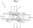
- 1 indicates a control valve according to the present invention.
- the valve 1 comprises a valve body 2. This body has an inlet opening 3 and an outlet opening 4 for the transit of a fluid.
- the valve body 2 can have any shape suitable to allow the passage of the fluid from the inlet opening 3 to the outlet opening 4.
- the valve body has a substantially tubular shape.
- the valve body 2 can have more complex shapes.
- valve 1 may not necessarily be in one direction.
- the present invention comprises a obturator 6 placed within the valve body 2.
- the obturator 6 is placed between the inlet 3 and outlet openings 4.
- the obturator 6 is configured so as to direct the fluid towards the recovery means 5 according to a desired direction and/or spatial distribution.
- the obturator 6 is further structured to assume a closing configuration in which it stops the flow of fluid and closes the valve 1.
- the obturator 6 can act as the trim of the valve 1.
- the obturator 6 contributes to limiting and/or preventing cavitation and/or choking phenomena. Different, particularly advantageous, embodiments of the obturator 6 will be described in detail in the present description as follows.
- the valve 1 comprises recovery means 5 configured to convert kinetic and/or potential energy of the fluid into mechanical work and to transfer such mechanical work outside the valve body 2.
- the recovery means 5 extract internal energy from the fluid and convert it into kinetic energy, particularly mechanical work.
- the energy extracted or recovered by the recovery means 5 is, in fact, translated into a load loss of the fluid which reduces its pressure.
- the recovery means 5 are contained within the valve body 2, that is, they do not require a separate containment body to be associated with the valve body 2. This enables the overall dimensions of the valve according to the present invention to be contained, and such dimensions to be kept substantially within the dimensions of the control valves currently available.
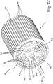
- the recovery means 5 comprise a rotating element 7 placed within the valve body 2, in particular downstream of the obturator 6.
- the rotating element 7 is configured to be put in rotation by the fluid transiting within the valve body 2, and has an axis of rotation "A".
- the axis of rotation "A" is fixed.
- the rotating element 7 comprises at least one blade 8, configured to intercept the flow of fluid and put the rotating element 7 in rotation.
- blade could mean any element adapted to interact with the fluid and to enable the development of aero/hydrodynamic forces that can put the rotating element 7 in rotation.
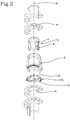
- the rotating element 7 has a substantially tubular and cylindrical structure.
- the rotating element 7 has an external wall 7a and a central portion 7b. Between the external wall 7a and the central portion 7b, an inner zone 7c is defined, in which the fluid transits.
- One or more blades 8 are placed at such inner zone 7c.
- the rotating element 7 and in particular the inner zone 7c is predisposed to be crossed by a flow of fluid that substantially flows parallel to the axis of rotation "A".
- the rotating element 7, and in particular the inner zone 7c is configured to guide the fluid along a path that is at least partially transversal to the axis of rotation "A" of the rotating element 7.
- the fluid follows a path, at least for a stretch, oriented along a radial direction.
- the central portion 7b has openings that place in communication the inner zone 7c with an inner zone of the central portion 7b.
- One or more blades 8 can be located within the central portion 7b.
- this embodiment is more suitable for lower flow rates and higher pressure variations.
- the rotating element 7 can have different dimensions according to the fluid dynamic performance to be obtained by the valve 1. It may comprise various tubular portions 71,72; in this case two are shown, each of which is provided with external blades 81,82. An inner tubular portion 71 may also be provided with inner blades 83.
- the presence of various tubular portions, each equipped with outer blades and/or inner blades, increases the amount of energy recovered by the rotating element.
- the presence of various tubular portions further allows the drop in pressure produced by the rotating element to be regulated. Directing the fluid towards a tubular portion or towards various tubular portions actually enables the drop in pressure produced in the fluid while it crosses the rotating element 7 to be regulated.
- valve according to the present invention causes a pressure drop in the fluid which is substantially transformed into kinetic energy of the rotating element 7 itself.
- the rotating cylinder can effectively control and limit flashing and cavitation phenomena, for uncompressible fluids, and choking, for compressible fluids. This drastically reduces the noisiness of the valve.
- the geometry of the blade or blades 8, that is the angle of inclination that they have with respect to the flow of fluid, and the extension that they have in the longitudinal direction allow the drop in pressure and maximum flow rate of fluid to be determined.
- the angle of inclination and the longitudinal extension of the blades 8 enable the pressure change required of the valve 1 to be produced gradually and not suddenly, transforming it into mechanical work.
- the structure of the rotating element 7 further allows losses in the form of vibrations and in the form of heat to be limited as much as possible, since the friction with the fluid is reduced drastically, hence the conversion into mechanical energy is as high as possible.
- the recovery means 5 comprise a stator (not illustrated) preferably associated with the valve body 2 and placed at the rotating element 7.
- the rotating element 7 itself defines a rotor electromagnetically coupled with said stator.
- this allows high conversion efficiency to be obtained, containing the dimensions.
- the recovery means 5 comprise an electrical energy generator (not shown) placed outside the valve body 2.
- Mechanical transmission means (not shown) are configured to transfer kinetic energy from the rotating element 7 to the generator.
- this configuration prevents electromagnetic coupling within the valve 1, and is preferable if the fluid transiting within the valve 1 is flammable.
- the mechanical transmission means are not further described since they are known by a person skilled in the art.
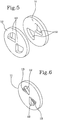
- the obturator 6 comprises at least a first 10 and a second plate 11 placed transversally to the axis of rotation "A" of the rotating element 7.
- the first 10 and the second plate 11 each have at least one passage opening 12.
- the first 10 and the second plate 11 are mobile with respect to each other to pass reversibly from a closed configuration, wherein the passage openings 12 are completely disaligned with respect to each other to prevent the passage of fluid, to at least one open configuration, wherein the passage openings 12 are at least partially overlapping to allow the passage of fluid.
- first 10 and the second plate 11 are preferably circular and arranged coaxially in order to be able to rotate between each other.
- the first 10 and the second plate 11 have a central axis which substantially coincides with the axis of rotation "A" of the rotating element 7.
- the passage openings 13 are substantially circular sector shaped.
- first plate 10 is preferably fixed to the valve body 2, while the second plate 11 is rotatably associated with the first plate 10.
- the first 10 and/or the second plate 11 comprise a grille 13 placed at the passage opening 12.
- the grille 13 can totally or partially occupy the passage opening 12, so as to obtain the fluid flow variation required by the particular application. Even more advantageously, the grille 13 contributes, where necessary, to preventing the cavitation of the fluid within the valve 1.
- a further advantage of the grille 13 is connected with the reduction in noise caused by the passage of fluid within the valve 1.
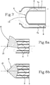
- the obturator 6 comprises a sliding element 14 associated with the inlet opening 3.
- the sliding element 14 is mobile moving away from/towards the inlet opening 3, so as to open and/or close it.
- the sliding element 14 is arranged coaxially with respect to the rotating element 7.
- the embodiment shown in figure 10 comprises a rotating element 7 provided with two tubular elements 71,72. Each tubular element may be reached by the fluid through radial openings 71a,72a afforded on the lateral wall of an axial conduit 141 along which the sliding element 14 is slidable. Sliding along said axial conduit 141, the sliding element 14 progressively uncovers the radial openings 71a,72a.
- the obturator 6 may be of the eccentric type, that is rotatable with respect to a hinge 15 placed transversally to the path of the fluid.
- the obturator 6 can rotate about a hinge 15 so as to open and/or close, even partially, the access to the rotating element 7.
- the obturator 6 could have a spherical sector or be a sphere.
- the obturator 6 comprises a single plate which has two portions 61,62 hinged to each other at a hinge axis P.
- Such portions 61,62 can rotated between a more open configuration, shown in figure 9 , wherein they close the passage to the fluid, and can move closer to each other rotating about the hinge axis to open the passage to the fluid, as represented with a broken line in figure 9 .
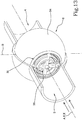
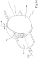
- the valve according to the present invention can comprise a deflector 31, interposed between the obturator 6 and the recovery means 5, structured to align the liquid flow parallel to a prefixed direction "F".
- the direction "F" is parallel to the longitudinal axis "X”.
- the deflector 31 comprises one or more vanes 32 that extend at least partially in a radial direction with respect to the prefixed direction F of the flow.
- the obturator comprises four vanes 32, arranged at right angles one with respect to the other and arranged radially with respect to the direction "F".
- vanes 32 it is obviously possible to provide a different number of vanes 32 or to use vanes of a different form or inclination, for example helical vanes on the basis of the kind of fluid to be treated and the conformation of the recovery means 5.
- FIG 12 for example, an embodiment is shown in which the flow direction F is parallel to the rotation axis "A" of the recovery means 5.
- the recovery means 5 are substantially the same as the ones in the embodiment shown in figure 9 , that is they comprise a rotating element 7 provided with two tubular portions 71, 72 that are concentric to the rotation axis "A", each of which is provided with external blades 81,82.
- the internal tubular portion 71 is also provided with inner blades 83.
- the deflector 31 is placed in front of the rotating element 7 with respect to the flow direction, that is located at the input of the rotating element 7.
- the deflector 31 can be provided with one or more annular segments 33 concentric one to the other. Said annular segments 33 help to improve the directionality of the flow, contributing in further limiting the turbulences, and allowing the passage of the liquid in the subsequent flow tubes defined between the tubular portions.
- two annular segments 33 are substantially aligned with the tubular portions 71, 72 of the rotating element 7, whereas a third annular segment 33 is positioned radially external with respect to blade 82 of the external tubular portion 72.
- the deflector 31 is preferably equipped with only two annular segments 33, one more internal aligned with the tubular portion 71 and one more external placed in a position radially external with respect to the blades 81 of the tubular portion 71.
- the obturator 6 comprises a rotating body 34, provided with a passage cavity 35, that is rotatable along a regulating axis B perpendicular to the longitudinal axis X.
- the recovery means 5 are located inside the passage cavity 35.
- the recovery means 5 are of the form in which they comprise a rotating element 7 that, in this case, is rotating inside the cavity 35.
- the rotating axis A of rotating element 7, in this case, is not fixed, but changes its orientation jointly to the rotation of the rotating body 34.
- the passage cavity 35 presents a longitudinal axis "S" and, when in use, the liquid to be treated flows through it.
- the rotating body 34 can rotate between at least an open position in which the passage cavity 35 puts in contact the inlet opening 3 with the outlet opening 4, and a closed position in which the passage cavity 35 is not in communication with the inlet and outlet openings 3,4.
- the rotating body 34 can rotate between at least a complete opening position, in which the longitudinal axis S of the passage cavity 35 is aligned with the longitudinal axis X of the valve, and a closing position, in which the passage cavity 35 does not face the inlet opening 3.
- An obturator 6 of the type as earlier described can be positioned at the end of the inlet of the passage cavity 35, upstream the rotating element 7.
- the obturator 6 can be of the spherical and/or of a generic rotation type, that can contain rotating means.
- this allows the specific shape of the valve 1 to be adapted to the different operating requirements.
Priority Applications (2)
| Application Number | Priority Date | Filing Date | Title |
|---|---|---|---|
| RS20190231A RS58383B1 (sr) | 2013-02-27 | 2014-02-25 | Ventil za podešavanje sa obnavljanjem energije |
| PL14728282T PL2961978T3 (pl) | 2013-02-27 | 2014-02-25 | Zawór regulujący z odzyskiwaniem energii |
Applications Claiming Priority (2)
| Application Number | Priority Date | Filing Date | Title |
|---|---|---|---|
| IT000051A ITMO20130051A1 (it) | 2013-02-27 | 2013-02-27 | "valvola di regolazione con recupero energetico" |
| PCT/IB2014/059229 WO2014132187A2 (en) | 2013-02-27 | 2014-02-25 | Control valve with energy recovery |
Publications (2)
| Publication Number | Publication Date |
|---|---|
| EP2961978A2 EP2961978A2 (en) | 2016-01-06 |
| EP2961978B1 true EP2961978B1 (en) | 2018-11-21 |
Family
ID=48096045
Family Applications (1)
| Application Number | Title | Priority Date | Filing Date |
|---|---|---|---|
| EP14728282.6A Active EP2961978B1 (en) | 2013-02-27 | 2014-02-25 | Adjustment valve with energy recovery |
Country Status (19)
| Country | Link |
|---|---|
| US (2) | US10458554B2 (tr) |
| EP (1) | EP2961978B1 (tr) |
| JP (1) | JP6567976B2 (tr) |
| KR (1) | KR20150122147A (tr) |
| CN (1) | CN105051363B (tr) |
| AU (1) | AU2014222344B2 (tr) |
| BR (1) | BR112015020440B8 (tr) |
| CA (1) | CA2900749A1 (tr) |
| DK (1) | DK2961978T3 (tr) |
| ES (1) | ES2712210T3 (tr) |
| IT (1) | ITMO20130051A1 (tr) |
| MX (1) | MX2015010994A (tr) |
| PL (1) | PL2961978T3 (tr) |
| PT (1) | PT2961978T (tr) |
| RS (1) | RS58383B1 (tr) |
| RU (1) | RU2689245C2 (tr) |
| SA (1) | SA515360938B1 (tr) |
| TR (1) | TR201902404T4 (tr) |
| WO (1) | WO2014132187A2 (tr) |
Families Citing this family (14)
| Publication number | Priority date | Publication date | Assignee | Title |
|---|---|---|---|---|
| US10648588B2 (en) | 2015-03-30 | 2020-05-12 | Politecnico Di Milano | Energy recovering flow control valves |
| GB2543566A (en) * | 2015-10-23 | 2017-04-26 | Sea-Lix As | Rotor apparatus |
| DE102015016357B4 (de) | 2015-12-17 | 2023-06-29 | Samson Aktiengesellschaft | Stellventil einer prozesstechnischen Anlage |
| US20190331236A1 (en) * | 2016-06-28 | 2019-10-31 | University Of Iowa Research Foundation | Rotary valve |
| US11324942B2 (en) * | 2016-06-28 | 2022-05-10 | Albert Rather, Jay K. Brama, Md, Gurjap Singh | Medical devices including rotary valve |
| US10113661B2 (en) * | 2016-08-30 | 2018-10-30 | Griswold Controls, Llc | Flow control valve |
| WO2018068849A1 (en) * | 2016-10-12 | 2018-04-19 | Energy Harvest As | Rotary valve device and liquid lifting device comprising the same |
| LU100555B1 (en) * | 2017-12-13 | 2019-06-28 | Luxembourg Inst Science & Tech List | Compact halbach electrical generator with coils arranged circumferentially |
| KR102025224B1 (ko) * | 2018-02-08 | 2019-09-25 | 김윤철 | 볼 밸브 |
| CN113039353B (zh) * | 2018-09-10 | 2023-09-29 | G.W.力士克有限公司 | 阀组件和方法 |
| CN112912290B (zh) * | 2018-10-16 | 2023-08-25 | 汉拿万都株式会社 | 电磁阀 |
| US11193598B2 (en) * | 2019-09-25 | 2021-12-07 | Control Components, Inc. | Low shear ball-type control valve |
| CN111594378A (zh) * | 2020-05-20 | 2020-08-28 | 南京晓庄学院 | 一种利用潮流能发电的海水淡化一体化装置 |
| CN112212119B (zh) * | 2020-09-30 | 2022-05-06 | 埃梯梯智慧水务科技有限公司 | 一种水管安全防爆系统 |
Family Cites Families (49)
| Publication number | Priority date | Publication date | Assignee | Title |
|---|---|---|---|---|
| US621864A (en) * | 1899-03-28 | Reducing-valve | ||
| US2436683A (en) * | 1945-04-06 | 1948-02-24 | Atlantic Pipe Line Company | Generator for pipe lines |
| US3620330A (en) * | 1969-04-14 | 1971-11-16 | Oldberg Mfg Co | Muffler construction and method of selectively modifying its sound-attenuating characteristics |
| US3590861A (en) * | 1969-05-05 | 1971-07-06 | Keelavite Hydraulics Ltd | Liquid flow control valves |
| FR2046342A5 (tr) * | 1970-04-22 | 1971-03-05 | Coq Ets | |
| US3784113A (en) * | 1972-09-11 | 1974-01-08 | American La France Inc | Nozzle |
| US4328831A (en) * | 1973-11-01 | 1982-05-11 | Wolff Robert C | Rotary valve |
| CH655556B (tr) * | 1984-03-16 | 1986-04-30 | ||
| DE3443491A1 (de) * | 1984-11-29 | 1986-05-28 | Klein, Schanzlin & Becker Ag, 6710 Frankenthal | Energierueckgewinnungsvorrichtung |
| US4809510A (en) * | 1985-01-24 | 1989-03-07 | Baker Cac, Inc. | Flowline power generator |
| JPH0325847Y2 (tr) * | 1987-03-09 | 1991-06-05 | ||
| CN2042543U (zh) * | 1988-06-06 | 1989-08-09 | 上海机械学院 | 流量调节阀 |
| CA1310682C (en) * | 1988-09-27 | 1992-11-24 | Kwc Ag | Water fitting, particularly for sanitary domestic installations |
| JPH0637096Y2 (ja) * | 1988-11-04 | 1994-09-28 | 株式会社イナックス | 水栓の制御装置 |
| US5143116A (en) * | 1989-12-11 | 1992-09-01 | Skoglund Paul K | Flow regulating valve and system using the same |
| US5092221A (en) * | 1990-09-28 | 1992-03-03 | The United States Of America As Represented By The Secretary Of The Navy | Launch container for multiple stores |
| ES2076765T3 (es) * | 1991-05-14 | 1995-11-01 | Theodora Antonia Teunissen | Medidor de caudal. |
| US5152465A (en) * | 1991-06-10 | 1992-10-06 | Calabro Daniel J | Shower flow controller |
| US5210962A (en) * | 1991-09-13 | 1993-05-18 | Jones Jr John B | Vertical shaft processor |
| JPH05106753A (ja) * | 1991-10-11 | 1993-04-27 | Kubota Corp | 発電装置内蔵バルブ |
| US5372048A (en) * | 1991-12-19 | 1994-12-13 | Muir Products, Inc. | Floating-type turbine flow meter |
| US5364540A (en) * | 1993-02-11 | 1994-11-15 | Emerson Electric Co. | Filter drier and method of filtering a fluid stream |
| IT1262631B (it) * | 1993-06-15 | 1996-07-04 | Valvola automatica di by-pass | |
| US5417083A (en) * | 1993-09-24 | 1995-05-23 | American Standard Inc. | In-line incremetally adjustable electronic expansion valve |
| US5664760A (en) * | 1995-04-06 | 1997-09-09 | United Technologies Corporation | Pressure regulation valve with integrated downstream pressure tap |
| ES2162680T3 (es) * | 1996-07-08 | 2002-01-01 | Alstom Power Inc | Punta de tobera para combustible solido pulverizado. |
| US6019003A (en) * | 1997-08-12 | 2000-02-01 | Cito Products, Inc. | Flow sensor turbine assembly with sapphire bearing and metallic insert |
| EP1254332B1 (de) * | 2000-01-25 | 2003-10-01 | Alois Schwarz | Ventil, insbesondere druckreduzierventil |
| US6824347B2 (en) * | 2002-12-30 | 2004-11-30 | Michael A. Maloney | Valve and related methods for reducing fluid pressure and generating power |
| US6945264B1 (en) * | 2004-07-09 | 2005-09-20 | Zurn Industries, Inc. | Flow control valve and method for using the same |
| ITMI20042191A1 (it) * | 2004-11-16 | 2005-02-16 | Armando Carravetta | Valvola di regolazione della pressione di valle a produzione di energia |
| US7385303B2 (en) * | 2005-09-01 | 2008-06-10 | Roos Paul W | Integrated fluid power conversion system |
| WO2007036944A2 (en) * | 2005-09-30 | 2007-04-05 | Hydro-Industries Tynat Ltd. | Self-powered non-contact water appliance |
| US8740183B2 (en) * | 2007-10-18 | 2014-06-03 | Burckhardt Compression Ag | Actively controlled valve and method for operating an actively controlled valve |
| US20090165866A1 (en) * | 2007-12-28 | 2009-07-02 | Giovanni Fima | Valve With Built-In Sensor |
| CA2644938A1 (en) * | 2008-11-12 | 2010-05-12 | Del Borle | System for generating power in a pipeline |
| US8141843B2 (en) * | 2008-12-31 | 2012-03-27 | Dresser, Inc. | Fluid control valve |
| US9574542B2 (en) * | 2009-12-04 | 2017-02-21 | Wave Power Renewables Limited | Turbines |
| GB2477124B (en) * | 2010-01-22 | 2017-04-19 | Lancaster Univ Business Entpr Ltd ( Lubel ) | Improved turbine |
| DE102010009215A1 (de) * | 2010-02-25 | 2011-08-25 | Guzman, Cristobal, 74363 | Strömungsregler für Flüssigkeiten mit Energieversorgung über die Strömung |
| US8807521B2 (en) * | 2010-05-25 | 2014-08-19 | Kerry Dunki-Jacobs | Flow control system |
| US9657464B2 (en) * | 2010-05-25 | 2017-05-23 | Kerry Dunki-Jacobs | Flow control system |
| US8876933B2 (en) * | 2010-12-08 | 2014-11-04 | Hamilton Sundstrand Corporation | Core diffuser for deoiler/breather |
| US9243604B2 (en) * | 2011-04-29 | 2016-01-26 | James Scott MONTGOMERY | In-pipe turbine |
| RU116946U1 (ru) | 2012-01-16 | 2012-06-10 | Общество с ограниченной ответственностью Научно-производственная фирма "МКТ-АСДМ" | Дроссель энергосберегающий |
| ITMI20120234A1 (it) * | 2012-02-16 | 2013-08-17 | Milano Politecnico | Valvola di regolazione a recupero di energia |
| US9316072B2 (en) * | 2012-04-06 | 2016-04-19 | Gyrodata, Incorporated | Valve for communication of a measurement while drilling system |
| US9739395B2 (en) * | 2014-01-09 | 2017-08-22 | Dresser-Rand Company | Grid valve apparatus |
| US10415137B2 (en) * | 2016-01-01 | 2019-09-17 | Applied Materials, Inc. | Non-metallic thermal CVD/ALD Gas Injector and Purge Systems |
-
2013
- 2013-02-27 IT IT000051A patent/ITMO20130051A1/it unknown
-
2014
- 2014-02-25 MX MX2015010994A patent/MX2015010994A/es unknown
- 2014-02-25 BR BR112015020440A patent/BR112015020440B8/pt active IP Right Grant
- 2014-02-25 ES ES14728282T patent/ES2712210T3/es active Active
- 2014-02-25 TR TR2019/02404T patent/TR201902404T4/tr unknown
- 2014-02-25 CA CA2900749A patent/CA2900749A1/en not_active Abandoned
- 2014-02-25 DK DK14728282.6T patent/DK2961978T3/en active
- 2014-02-25 US US14/765,178 patent/US10458554B2/en active Active
- 2014-02-25 WO PCT/IB2014/059229 patent/WO2014132187A2/en active Application Filing
- 2014-02-25 CN CN201480009789.5A patent/CN105051363B/zh active Active
- 2014-02-25 PL PL14728282T patent/PL2961978T3/pl unknown
- 2014-02-25 AU AU2014222344A patent/AU2014222344B2/en active Active
- 2014-02-25 RU RU2015133446A patent/RU2689245C2/ru active
- 2014-02-25 EP EP14728282.6A patent/EP2961978B1/en active Active
- 2014-02-25 JP JP2015558596A patent/JP6567976B2/ja not_active Expired - Fee Related
- 2014-02-25 PT PT14728282T patent/PT2961978T/pt unknown
- 2014-02-25 RS RS20190231A patent/RS58383B1/sr unknown
- 2014-02-25 KR KR1020157023022A patent/KR20150122147A/ko not_active Application Discontinuation
-
2015
- 2015-08-23 SA SA515360938A patent/SA515360938B1/ar unknown
-
2019
- 2019-09-17 US US16/573,699 patent/US20200011430A1/en not_active Abandoned
Non-Patent Citations (1)
| Title |
|---|
| None * |
Also Published As
| Publication number | Publication date |
|---|---|
| JP6567976B2 (ja) | 2019-08-28 |
| RU2015133446A (ru) | 2017-03-31 |
| ES2712210T3 (es) | 2019-05-09 |
| JP2016513227A (ja) | 2016-05-12 |
| BR112015020440A2 (pt) | 2017-07-18 |
| BR112015020440B8 (pt) | 2023-03-21 |
| EP2961978A2 (en) | 2016-01-06 |
| US20200011430A1 (en) | 2020-01-09 |
| WO2014132187A2 (en) | 2014-09-04 |
| US10458554B2 (en) | 2019-10-29 |
| CN105051363A (zh) | 2015-11-11 |
| RS58383B1 (sr) | 2019-04-30 |
| TR201902404T4 (tr) | 2019-03-21 |
| US20150369375A1 (en) | 2015-12-24 |
| MX2015010994A (es) | 2016-04-07 |
| KR20150122147A (ko) | 2015-10-30 |
| AU2014222344B2 (en) | 2017-06-01 |
| BR112015020440B1 (pt) | 2022-05-10 |
| SA515360938B1 (ar) | 2019-02-17 |
| AU2014222344A1 (en) | 2015-08-13 |
| PL2961978T3 (pl) | 2019-05-31 |
| CN105051363B (zh) | 2018-11-06 |
| RU2689245C2 (ru) | 2019-05-24 |
| CA2900749A1 (en) | 2014-09-04 |
| ITMO20130051A1 (it) | 2014-08-28 |
| PT2961978T (pt) | 2019-02-26 |
| DK2961978T3 (en) | 2019-03-18 |
| WO2014132187A3 (en) | 2015-01-22 |
Similar Documents
| Publication | Publication Date | Title |
|---|---|---|
| EP2961978B1 (en) | Adjustment valve with energy recovery | |
| US3514074A (en) | High energy loss fluid control | |
| CA2864054C (en) | Energy recovering flow control valve | |
| EP2252814B1 (en) | Fluid flow control valve | |
| BRPI0513789A (pt) | trocador de pressão | |
| CN107429859B (zh) | 能量回收用流量控制阀 | |
| US10578215B2 (en) | Inline high-recovery flow control valve | |
| EP3056689B1 (en) | Governing valve device and power generating equipment | |
| RU2620616C1 (ru) | Регулирующий клапан осевого типа | |
| JP4896134B2 (ja) | チョークバルブ装置 | |
| WO2021071738A1 (en) | Additively manufactured control valve flow element | |
| US8869832B2 (en) | Variable resistance device | |
| KR101652496B1 (ko) | 보텍스 튜브 | |
| Zaryankin et al. | Development and investigation of a new rotary valve for power steam turbines | |
| EP2740978A1 (en) | Energy saving control valve | |
| HUE028280T2 (en) | Regulating ball valve | |
| RU2781394C1 (ru) | Осевой клапан | |
| RU2338107C1 (ru) | Клапан регулирующий | |
| WO2010020741A1 (en) | Fluid flow control valve | |
| RU2692582C1 (ru) | Осевой регулирующий клапан | |
| KR20170064859A (ko) | 와류 방지용 압력감쇄부재를 구비한 버터플라이 밸브 | |
| RU2101643C1 (ru) | Способ оптимизации характеристик вихревого теплообменного элемента | |
| RU59762U1 (ru) | Регулятор давления | |
| KR20040064200A (ko) | 나선형 앵글 밸브 |
Legal Events
| Date | Code | Title | Description |
|---|---|---|---|
| PUAI | Public reference made under article 153(3) epc to a published international application that has entered the european phase |
Free format text: ORIGINAL CODE: 0009012 |
|
| 17P | Request for examination filed |
Effective date: 20150729 |
|
| AK | Designated contracting states |
Kind code of ref document: A2 Designated state(s): AL AT BE BG CH CY CZ DE DK EE ES FI FR GB GR HR HU IE IS IT LI LT LU LV MC MK MT NL NO PL PT RO RS SE SI SK SM TR |
|
| AX | Request for extension of the european patent |
Extension state: BA ME |
|
| STAA | Information on the status of an ep patent application or granted ep patent |
Free format text: STATUS: EXAMINATION IS IN PROGRESS |
|
| 17Q | First examination report despatched |
Effective date: 20170214 |
|
| GRAP | Despatch of communication of intention to grant a patent |
Free format text: ORIGINAL CODE: EPIDOSNIGR1 |
|
| STAA | Information on the status of an ep patent application or granted ep patent |
Free format text: STATUS: GRANT OF PATENT IS INTENDED |
|
| RIC1 | Information provided on ipc code assigned before grant |
Ipc: F16K 3/08 20060101ALI20180517BHEP Ipc: F16K 47/12 20060101ALI20180517BHEP Ipc: F16K 47/08 20060101ALI20180517BHEP Ipc: F03B 11/00 20060101ALI20180517BHEP Ipc: F03B 15/04 20060101ALI20180517BHEP Ipc: F03B 13/00 20060101AFI20180517BHEP |
|
| INTG | Intention to grant announced |
Effective date: 20180615 |
|
| RAP1 | Party data changed (applicant data changed or rights of an application transferred) |
Owner name: LOCLAIN S.R.L. |
|
| GRAS | Grant fee paid |
Free format text: ORIGINAL CODE: EPIDOSNIGR3 |
|
| GRAA | (expected) grant |
Free format text: ORIGINAL CODE: 0009210 |
|
| STAA | Information on the status of an ep patent application or granted ep patent |
Free format text: STATUS: THE PATENT HAS BEEN GRANTED |
|
| AK | Designated contracting states |
Kind code of ref document: B1 Designated state(s): AL AT BE BG CH CY CZ DE DK EE ES FI FR GB GR HR HU IE IS IT LI LT LU LV MC MK MT NL NO PL PT RO RS SE SI SK SM TR |
|
| AX | Request for extension of the european patent |
Extension state: BA ME |
|
| REG | Reference to a national code |
Ref country code: CH Ref legal event code: EP |
|
| REG | Reference to a national code |
Ref country code: IE Ref legal event code: FG4D |
|
| REG | Reference to a national code |
Ref country code: AT Ref legal event code: REF Ref document number: 1067839 Country of ref document: AT Kind code of ref document: T Effective date: 20181215 |
|
| REG | Reference to a national code |
Ref country code: DE Ref legal event code: R096 Ref document number: 602014036450 Country of ref document: DE |
|
| REG | Reference to a national code |
Ref country code: CH Ref legal event code: NV Representative=s name: BUGNION S.A., CH |
|
| REG | Reference to a national code |
Ref country code: RO Ref legal event code: EPE |
|
| REG | Reference to a national code |
Ref country code: PT Ref legal event code: SC4A Ref document number: 2961978 Country of ref document: PT Date of ref document: 20190226 Kind code of ref document: T Free format text: AVAILABILITY OF NATIONAL TRANSLATION Effective date: 20190219 |
|
| REG | Reference to a national code |
Ref country code: DK Ref legal event code: T3 Effective date: 20190311 |
|
| REG | Reference to a national code |
Ref country code: SE Ref legal event code: TRGR |
|
| REG | Reference to a national code |
Ref country code: NL Ref legal event code: FP |
|
| PG25 | Lapsed in a contracting state [announced via postgrant information from national office to epo] |
Ref country code: IS Free format text: LAPSE BECAUSE OF FAILURE TO SUBMIT A TRANSLATION OF THE DESCRIPTION OR TO PAY THE FEE WITHIN THE PRESCRIBED TIME-LIMIT Effective date: 20190321 Ref country code: BG Free format text: LAPSE BECAUSE OF FAILURE TO SUBMIT A TRANSLATION OF THE DESCRIPTION OR TO PAY THE FEE WITHIN THE PRESCRIBED TIME-LIMIT Effective date: 20190221 Ref country code: HR Free format text: LAPSE BECAUSE OF FAILURE TO SUBMIT A TRANSLATION OF THE DESCRIPTION OR TO PAY THE FEE WITHIN THE PRESCRIBED TIME-LIMIT Effective date: 20181121 Ref country code: LT Free format text: LAPSE BECAUSE OF FAILURE TO SUBMIT A TRANSLATION OF THE DESCRIPTION OR TO PAY THE FEE WITHIN THE PRESCRIBED TIME-LIMIT Effective date: 20181121 Ref country code: LV Free format text: LAPSE BECAUSE OF FAILURE TO SUBMIT A TRANSLATION OF THE DESCRIPTION OR TO PAY THE FEE WITHIN THE PRESCRIBED TIME-LIMIT Effective date: 20181121 |
|
| REG | Reference to a national code |
Ref country code: NO Ref legal event code: T2 Effective date: 20181121 |
|
| REG | Reference to a national code |
Ref country code: ES Ref legal event code: FG2A Ref document number: 2712210 Country of ref document: ES Kind code of ref document: T3 Effective date: 20190509 |
|
| PG25 | Lapsed in a contracting state [announced via postgrant information from national office to epo] |
Ref country code: AL Free format text: LAPSE BECAUSE OF FAILURE TO SUBMIT A TRANSLATION OF THE DESCRIPTION OR TO PAY THE FEE WITHIN THE PRESCRIBED TIME-LIMIT Effective date: 20181121 Ref country code: GR Free format text: LAPSE BECAUSE OF FAILURE TO SUBMIT A TRANSLATION OF THE DESCRIPTION OR TO PAY THE FEE WITHIN THE PRESCRIBED TIME-LIMIT Effective date: 20190222 |
|
| PG25 | Lapsed in a contracting state [announced via postgrant information from national office to epo] |
Ref country code: IT Free format text: LAPSE BECAUSE OF FAILURE TO SUBMIT A TRANSLATION OF THE DESCRIPTION OR TO PAY THE FEE WITHIN THE PRESCRIBED TIME-LIMIT Effective date: 20181121 Ref country code: CZ Free format text: LAPSE BECAUSE OF FAILURE TO SUBMIT A TRANSLATION OF THE DESCRIPTION OR TO PAY THE FEE WITHIN THE PRESCRIBED TIME-LIMIT Effective date: 20181121 |
|
| REG | Reference to a national code |
Ref country code: DE Ref legal event code: R097 Ref document number: 602014036450 Country of ref document: DE |
|
| PG25 | Lapsed in a contracting state [announced via postgrant information from national office to epo] |
Ref country code: SK Free format text: LAPSE BECAUSE OF FAILURE TO SUBMIT A TRANSLATION OF THE DESCRIPTION OR TO PAY THE FEE WITHIN THE PRESCRIBED TIME-LIMIT Effective date: 20181121 Ref country code: SM Free format text: LAPSE BECAUSE OF FAILURE TO SUBMIT A TRANSLATION OF THE DESCRIPTION OR TO PAY THE FEE WITHIN THE PRESCRIBED TIME-LIMIT Effective date: 20181121 Ref country code: EE Free format text: LAPSE BECAUSE OF FAILURE TO SUBMIT A TRANSLATION OF THE DESCRIPTION OR TO PAY THE FEE WITHIN THE PRESCRIBED TIME-LIMIT Effective date: 20181121 |
|
| PLBE | No opposition filed within time limit |
Free format text: ORIGINAL CODE: 0009261 |
|
| STAA | Information on the status of an ep patent application or granted ep patent |
Free format text: STATUS: NO OPPOSITION FILED WITHIN TIME LIMIT |
|
| 26N | No opposition filed |
Effective date: 20190822 |
|
| PG25 | Lapsed in a contracting state [announced via postgrant information from national office to epo] |
Ref country code: LU Free format text: LAPSE BECAUSE OF NON-PAYMENT OF DUE FEES Effective date: 20190225 Ref country code: SI Free format text: LAPSE BECAUSE OF FAILURE TO SUBMIT A TRANSLATION OF THE DESCRIPTION OR TO PAY THE FEE WITHIN THE PRESCRIBED TIME-LIMIT Effective date: 20181121 Ref country code: MC Free format text: LAPSE BECAUSE OF FAILURE TO SUBMIT A TRANSLATION OF THE DESCRIPTION OR TO PAY THE FEE WITHIN THE PRESCRIBED TIME-LIMIT Effective date: 20181121 |
|
| PG25 | Lapsed in a contracting state [announced via postgrant information from national office to epo] |
Ref country code: MT Free format text: LAPSE BECAUSE OF NON-PAYMENT OF DUE FEES Effective date: 20190225 |
|
| REG | Reference to a national code |
Ref country code: AT Ref legal event code: UEP Ref document number: 1067839 Country of ref document: AT Kind code of ref document: T Effective date: 20181121 |
|
| PGFP | Annual fee paid to national office [announced via postgrant information from national office to epo] |
Ref country code: NO Payment date: 20210226 Year of fee payment: 8 Ref country code: IE Payment date: 20210224 Year of fee payment: 8 |
|
| PG25 | Lapsed in a contracting state [announced via postgrant information from national office to epo] |
Ref country code: CY Free format text: LAPSE BECAUSE OF FAILURE TO SUBMIT A TRANSLATION OF THE DESCRIPTION OR TO PAY THE FEE WITHIN THE PRESCRIBED TIME-LIMIT Effective date: 20181121 |
|
| PGFP | Annual fee paid to national office [announced via postgrant information from national office to epo] |
Ref country code: TR Payment date: 20210224 Year of fee payment: 8 |
|
| PG25 | Lapsed in a contracting state [announced via postgrant information from national office to epo] |
Ref country code: HU Free format text: LAPSE BECAUSE OF FAILURE TO SUBMIT A TRANSLATION OF THE DESCRIPTION OR TO PAY THE FEE WITHIN THE PRESCRIBED TIME-LIMIT; INVALID AB INITIO Effective date: 20140225 |
|
| REG | Reference to a national code |
Ref country code: DE Ref legal event code: R081 Ref document number: 602014036450 Country of ref document: DE Owner name: VALPRES S.R.L., MARCHENO, IT Free format text: FORMER OWNER: LOCLAIN S.R.L., IMOLA, BOLOGNA, IT |
|
| REG | Reference to a national code |
Ref country code: NL Ref legal event code: PD Owner name: VALPRES S.R.L.; IT Free format text: DETAILS ASSIGNMENT: CHANGE OF OWNER(S), ASSIGNMENT; FORMER OWNER NAME: LOCLAIN S.R.L. Effective date: 20220615 Ref country code: NL Ref legal event code: HC Owner name: LOCLAIN SRL IN LIQUIDAZIONE; IT Free format text: DETAILS ASSIGNMENT: CHANGE OF OWNER(S), CHANGE OF OWNER(S) NAME; FORMER OWNER NAME: LOCLAIN S.R.L. Effective date: 20220615 |
|
| PG25 | Lapsed in a contracting state [announced via postgrant information from national office to epo] |
Ref country code: MK Free format text: LAPSE BECAUSE OF FAILURE TO SUBMIT A TRANSLATION OF THE DESCRIPTION OR TO PAY THE FEE WITHIN THE PRESCRIBED TIME-LIMIT Effective date: 20181121 |
|
| REG | Reference to a national code |
Ref country code: NO Ref legal event code: CHAD Owner name: LOCLAIN SRL IN LIQUIDATION, 40026 IMOLA, ITALIA |
|
| REG | Reference to a national code |
Ref country code: NO Ref legal event code: CHAD Owner name: VALPRES S.R.L., IT |
|
| REG | Reference to a national code |
Ref country code: NO Ref legal event code: CHAD Owner name: VALPRES S.R.L., IT |
|
| REG | Reference to a national code |
Ref country code: GB Ref legal event code: 732E Free format text: REGISTERED BETWEEN 20220721 AND 20220727 |
|
| REG | Reference to a national code |
Ref country code: FI Ref legal event code: PCE Owner name: VALPRES S.R.L. |
|
| REG | Reference to a national code |
Ref country code: AT Ref legal event code: PC Ref document number: 1067839 Country of ref document: AT Kind code of ref document: T Owner name: VALPRES S.R.L., IT Effective date: 20220715 |
|
| REG | Reference to a national code |
Ref country code: NO Ref legal event code: MMEP |
|
| REG | Reference to a national code |
Ref country code: BE Ref legal event code: PD Owner name: VALPRES S.R.L.; IT Free format text: DETAILS ASSIGNMENT: CHANGE OF OWNER(S), ASSIGNMENT; FORMER OWNER NAME: LOCLAIN SRL IN LIQUIDAZIONE Effective date: 20220629 Ref country code: BE Ref legal event code: HC Owner name: LOCLAIN SRL IN LIQUIDAZIONE; IT Free format text: DETAILS ASSIGNMENT: CHANGE OF OWNER(S), CHANGE OF OWNER(S) NAME; FORMER OWNER NAME: LOCLAIN S.R.L. Effective date: 20220629 |
|
| REG | Reference to a national code |
Ref country code: ES Ref legal event code: PC2A Owner name: VALPRES S.R.L. Effective date: 20221019 |
|
| PG25 | Lapsed in a contracting state [announced via postgrant information from national office to epo] |
Ref country code: NO Free format text: LAPSE BECAUSE OF NON-PAYMENT OF DUE FEES Effective date: 20220228 |
|
| PG25 | Lapsed in a contracting state [announced via postgrant information from national office to epo] |
Ref country code: IE Free format text: LAPSE BECAUSE OF NON-PAYMENT OF DUE FEES Effective date: 20220225 |
|
| PGFP | Annual fee paid to national office [announced via postgrant information from national office to epo] |
Ref country code: NL Payment date: 20230222 Year of fee payment: 10 |
|
| PGFP | Annual fee paid to national office [announced via postgrant information from national office to epo] |
Ref country code: RO Payment date: 20230208 Year of fee payment: 10 Ref country code: FR Payment date: 20230223 Year of fee payment: 10 Ref country code: FI Payment date: 20230223 Year of fee payment: 10 Ref country code: ES Payment date: 20230321 Year of fee payment: 10 Ref country code: DK Payment date: 20230223 Year of fee payment: 10 Ref country code: CH Payment date: 20230307 Year of fee payment: 10 Ref country code: AT Payment date: 20230215 Year of fee payment: 10 |
|
| PGFP | Annual fee paid to national office [announced via postgrant information from national office to epo] |
Ref country code: SE Payment date: 20230222 Year of fee payment: 10 Ref country code: RS Payment date: 20230206 Year of fee payment: 10 Ref country code: PT Payment date: 20230206 Year of fee payment: 10 Ref country code: PL Payment date: 20230210 Year of fee payment: 10 Ref country code: GB Payment date: 20230214 Year of fee payment: 10 Ref country code: DE Payment date: 20230227 Year of fee payment: 10 Ref country code: BE Payment date: 20230222 Year of fee payment: 10 |
|
| P01 | Opt-out of the competence of the unified patent court (upc) registered |
Effective date: 20231213 |