EP2961504B2 - Modulares befestigungsplattensystem zum positionieren eines werkstücks während eines fertigungs- und/oder prüfverfahrens - Google Patents
Modulares befestigungsplattensystem zum positionieren eines werkstücks während eines fertigungs- und/oder prüfverfahrens Download PDFInfo
- Publication number
- EP2961504B2 EP2961504B2 EP14757128.5A EP14757128A EP2961504B2 EP 2961504 B2 EP2961504 B2 EP 2961504B2 EP 14757128 A EP14757128 A EP 14757128A EP 2961504 B2 EP2961504 B2 EP 2961504B2
- Authority
- EP
- European Patent Office
- Prior art keywords
- plate
- interlocking
- fixture
- fixture plate
- docking
- Prior art date
- Legal status (The legal status is an assumption and is not a legal conclusion. Google has not performed a legal analysis and makes no representation as to the accuracy of the status listed.)
- Active
Links
Images


Classifications
-
- B—PERFORMING OPERATIONS; TRANSPORTING
- B25—HAND TOOLS; PORTABLE POWER-DRIVEN TOOLS; MANIPULATORS
- B25B—TOOLS OR BENCH DEVICES NOT OTHERWISE PROVIDED FOR, FOR FASTENING, CONNECTING, DISENGAGING OR HOLDING
- B25B11/00—Work holders not covered by any preceding group in the subclass, e.g. magnetic work holders, vacuum work holders
-
- B—PERFORMING OPERATIONS; TRANSPORTING
- B23—MACHINE TOOLS; METAL-WORKING NOT OTHERWISE PROVIDED FOR
- B23Q—DETAILS, COMPONENTS, OR ACCESSORIES FOR MACHINE TOOLS, e.g. ARRANGEMENTS FOR COPYING OR CONTROLLING; MACHINE TOOLS IN GENERAL CHARACTERISED BY THE CONSTRUCTION OF PARTICULAR DETAILS OR COMPONENTS; COMBINATIONS OR ASSOCIATIONS OF METAL-WORKING MACHINES, NOT DIRECTED TO A PARTICULAR RESULT
- B23Q1/00—Members which are comprised in the general build-up of a form of machine, particularly relatively large fixed members
- B23Q1/03—Stationary work or tool supports
-
- B—PERFORMING OPERATIONS; TRANSPORTING
- B23—MACHINE TOOLS; METAL-WORKING NOT OTHERWISE PROVIDED FOR
- B23Q—DETAILS, COMPONENTS, OR ACCESSORIES FOR MACHINE TOOLS, e.g. ARRANGEMENTS FOR COPYING OR CONTROLLING; MACHINE TOOLS IN GENERAL CHARACTERISED BY THE CONSTRUCTION OF PARTICULAR DETAILS OR COMPONENTS; COMBINATIONS OR ASSOCIATIONS OF METAL-WORKING MACHINES, NOT DIRECTED TO A PARTICULAR RESULT
- B23Q3/00—Devices holding, supporting, or positioning work or tools, of a kind normally removable from the machine
- B23Q3/02—Devices holding, supporting, or positioning work or tools, of a kind normally removable from the machine for mounting on a work-table, tool-slide, or analogous part
-
- B—PERFORMING OPERATIONS; TRANSPORTING
- B23—MACHINE TOOLS; METAL-WORKING NOT OTHERWISE PROVIDED FOR
- B23Q—DETAILS, COMPONENTS, OR ACCESSORIES FOR MACHINE TOOLS, e.g. ARRANGEMENTS FOR COPYING OR CONTROLLING; MACHINE TOOLS IN GENERAL CHARACTERISED BY THE CONSTRUCTION OF PARTICULAR DETAILS OR COMPONENTS; COMBINATIONS OR ASSOCIATIONS OF METAL-WORKING MACHINES, NOT DIRECTED TO A PARTICULAR RESULT
- B23Q37/00—Metal-working machines, or constructional combinations thereof, built-up from units designed so that at least some of the units can form parts of different machines or combinations; Units therefor in so far as the feature of interchangeability is important
- B23Q37/005—Modular base frames
Definitions
- This invention relates to methods and apparatus for manufacturing and/or inspection processes, and more particularly to methods and apparatus for positioning a workpiece during a manufacturing and/or inspection process.
- processes such as quality inspection, laser marking and etching, fiber laser and laser machining, dot peen marking, pad printing and routing all require accurate, repeatable positioning of a workpiece.
- a workpiece is typically held in a specific position while work is performed on the workpiece, and then the workpiece is "swapped out" for a new workpiece which is to be worked on.
- This new workpiece generally needs to be placed in the same, repeatable position as the preceding workpiece in order for the work process to be performed accurately.
- metal and/or plastic fixture plates are typically affixed to inspection machines to facilitate the quality inspection of previously-manufactured workpieces (i.e., to test the correctness of the manufactured workpieces).
- These fixture plates generally comprise a pattern of threaded holes formed therein which accept workpiece-holding elements such as screws, clamps, magnets, hold-downs, etc.
- workpiece-holding elements such as screws, clamps, magnets, hold-downs, etc
- the previously-manufactured workpiece is placed on these metal and/or plastic fixture plates, held down with the workpiece-holding elements and then the previously-manufactured workpiece is measured for correctness. Once the workpiece on the fixture plate has been inspected, the workpiece is replaced by another workpiece which is to be inspected using the same inspection set-up, fixture plates, etc.
- fixture plates are currently a one-piece design and are made to fit the workbed area of a particular inspection machine.
- different sizes of fixture plates must be provided for different inspection machines, thereby presenting an inventory issue or requiring long lead-times to custom manufacture fixture plates.
- workpieces vary in size and, in many cases, a workpiece may be relatively small and take up only a small fraction of the complete surface area of the fixture plate provided for a given inspection machine. In this case, the remainder of the fixture plate is essentially unused during the quality inspection process.
- these "light duty" manufacturing machines In a manner similar to a quality inspection machine, these "light duty" manufacturing machines generally have a work surface on which the workpiece is supported during processing.
- the laser etching of part numbers on workpieces is a very common practice.
- logo's, bar codes and/or other markings are also routinely added to workpieces.
- EP 2 292 381 A1 discloses a clamping system for fixing workpieces, comprising a stop element, at least two cantilevers and at least one clamping bracket, wherein in the stop element, in the cantilevers and in the clamping bracket, means are provided for the positive-locking, screwless connection of the stop element to the cantilevers on the one hand, and for connecting of the cantilevers to the clamping bracket on the other hand, for the creation of a stable frame. None of the relevant parts of such clamping system has a plate-like shape.
- US 5 052 158 A discloses a modular locking floor covering.
- the present invention provides a new and improved fixture plate system for positioning a workpiece during a quality inspection process and/or "light duty" manufacturing process, wherein the improved fixture plate system uses a modular approach to allow for the creation of simple but effective fixture assemblies that can provide fast, easy and repeatable setups for a specific production run.
- the present invention provides a new and improved fixture plate system for positioning a workpiece during a quality inspection process and/or "light duty" manufacturing process, wherein the improved fixture plate system uses a modular approach to allow for the creation of simple but effective fixture assemblies that can provide fast, easy and repeatable setups for a specific production run.
- the present invention comprises a new modular fixture plate system which allows for, and encourages, lean manufacturing principles for, but not limited to, quality inspection processes and "light duty" manufacturing processes such as laser marking and etching, fiber laser and laser machining, dot peen marking, pad printing and routing processes. More particularly, the present invention comprises a modular fixture plate system which comprises a plurality of interlocking plates which are selected, and then assembled together, so as to form a complete fixture plate, or which can be used individually so as to allow a portion of the workbed area of the inspection or manufacturing machine to be exposed, with the specific interlocking plates used being selected according to the size of the workpiece which is to be held, so that only those interlocking plates are used which are required to hold the workpiece of interest.
- a workpiece may be set up and programmed for inspection or working on a single interlocking plate, which can then be easily positioned on the inspection or manufacturing machine, the workpiece inspected or worked, then the workpiece and interlocking plate may be removed as a unit from the workbed of the inspection or manufacturing machine and thereafter be replaced by another workpiece and interlocking plate.
- the new modular fixture plate system of the present invention encourages inspectors and machine operators to employ lean manufacturing principles in the inspection and "light duty” manufacturing processes, using the minimum resources required, and enhances the value and investment of the inspection and "light duty” manufacturing equipment.
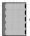
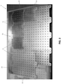
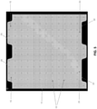
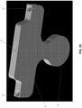
- Modular plate system 5 generally comprises one or more interlocking fixture plates 10 which are intended to be positioned on the workbed 12 of an inspection or "light duty" manufacturing machine.
- Each interlocking fixture plate 10 comprises a male end 15 and a female end 20, wherein male end 15 comprises at least one male projection 25 and female end 20 comprises at least one female recess 30.
- the interlocking fixture plates 10 comprise a plurality of threaded holes 32, preferably disposed in a regular pattern, for accepting workpiece-holding elements well known in the art, e.g., screws, clamps, magnets, hold-downs, etc.
- interlocking fixture plates 10 can be formed in a variety of configurations, each with one or more male projections 25 and one or more female recesses 30.
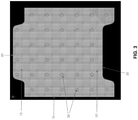
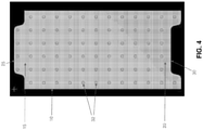
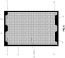
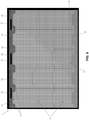
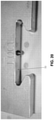
- Modular plate system 5 also comprises a docking plate 35 ( Figs. 1 , 2 , 7 and 8 ) which is intended to be affixed to the workbed of the inspection or "light duty" manufacturing machine, e.g., using an adhesive in which case the docking plate may comprise a solid structure ( Figs. 1 and 2 ) or using bolts which extend through counterbored slots 40 formed in docking plate 35 ( Figs. 7 and 8 ).
- Docking plate 35 comprises a plurality of female recesses 30 ( Figs.
- LOCs also sometimes referred to herein as "Locations” or “LOCs”, which receive male projections 25 of one or more interlocking fixture plates 10 or, alternatively, docking plate 35 comprises a plurality of male projections 25 for projecting into female recesses 30 of one or more interlocking fixture plates 10 ( Fig. 9 ) .
- Docking plate 35 and the various interlocking fixture plates 10 are designed to fit tightly together in an interlocked manner, with a male projection 25 of one element being received in a female recess 30 of another element.
- docking plate 35 comprises a plurality of female recesses 30 ( Figs. 1 , 2 and 9 )
- a plurality of interlocking fixture plates 10 may be interlocked with docking plate 35, and also with one another, by projecting the male projections 25 of some of the interlocking fixture plates 10 into the female recesses 30 of docking plate 35 and by projecting the male projections 25 of others of the interlocking fixture plates 10 into the female recesses 30 of the interlocking fixture plates 10 interlocked with docking plate 35.
- a docking plate 35 having a plurality of male projections 25 may be interlocked with interlocking fixture plates 10 by projecting the male projections of docking plate 35 into the female recesses of interlocking fixture plates 10 ( Fig. 9 ).
- interlocking fixture plates 10 can be interlocked with one another, and with docking plate 35, so as to cover some or all of the workbed of an inspection or manufacturing machine, and a large workpiece can span a number of interlocked fixture plates 10.
- interlocking fixture plates 10 fit together (e.g., in the manner of a jigsaw puzzle) to collectively create the desired overall size for the fixture plate.
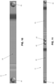
- docking plate 35 and the various interlocking fixture plates 10 are further secured to one another by magnets 45 which are disposed adjacent to male projections 25 of interlocking fixture plates 10 ( Figs. 10 and 11 ) and adjacent to female recesses 30 of interlocking fixture plates 10 ( Figs. 12 and 13 ), and by magnets 45 which are disposed adjacent to female recesses 30 of docking plate 35 ( Fig. 14 ) and adjacent to male projections 25 of docking plate 35 ( Figs. 15 and 16 ).
- magnets 45 are inset into docking plate 35 and interlocking fixture plates 10 so that the magnets of one plate mate with the magnets of an adjoining plate when a male projection 25 is received in a female recess 30.
- magnets 45 to secure docking plate 35 and interlocking fixture plates 10 to one another allow interlocking fixture plates 10 to be easily released from one another, and from docking plate 35, by hand and without the use of tools, whereby to enable interlocking fixture plates 10 to be quickly and easily swapped out as needed.
- a spring plunger set screw may be used to secure docking plate 35 and the various interlocking fixture plates 10 to one another.
- two or more docking plates 35 may be used in opposing arrangement ( Fig. 9 ) so as to lock the interlocking fixture plates 10 in position.
- modular fixture plate system 5 may also comprise a base plate 50 ( Fig. 17 ) on which the remainder of the system (e.g., docking plate 35 and one or more interlocking fixture plates 10) may be mounted.
- one preferred form of the invention may provide an interlocking fixture plate 10 which interlocks with only docking plate 35 ( Fig. 17 ), with the opposite end of interlocking fixture plate 10 being straight and with or without a handle or finger grip for easier removal of interlocking fixture plate 10.
- modular plate system 5 may provide docking plates 35 on all sides of interlocking fixture plates 10 so that the interlocking fixture plates 10 are interlocked, much like the pieces of a puzzle.
- the aforementioned magnets 45 can be omitted.
- male projections 25 and female recesses 30 may utilize a dovetail configuration ( Figs. 18-20 ).
- each of the interlocks of an interlocking fixture plate 10 with a docking plate 35 can be assigned a "Location” or “LOC” number (see Figs. 2 , 7 , 9 , 20 and 21 ). Inspection and manufacturing programs can be written and assigned to a specific "Location” or “LOC” number, i.e., to a specific location of an interlocking fixture plate 10 relative to docking plate 35.
- Programming inspection and manufacturing setups based on the interlocking fixture plate location or assignment allows for faster repeat setups and allows for more than one setup per machine (i.e., it permits work to be effected at LOCI, LOC2, LOC3, etc.), thereby speeding up the inspection and manufacturing processes.
- the hole pattern (i.e., the pattern of the holes 32 provided in interlocking fixture plates 10) is preferably consistent and seamless across all interlocking fixture plates 10 ( Fig. 1 and 2 ).
- a 1 ⁇ 4-20 or M6 threaded hole pattern with 1 inch spacing is shown in Figs. 1 and 2 .
- the described thread and hole pattern is typical of the industry, however, it can vary widely in thread size and hole spacing without departing from the scope of the present invention.
- interlocking fixture plates 10 can be created as "blanks" (i.e., without holes 32) so that the end user can then add the holes 32 in the sizes and/or patterns desired.
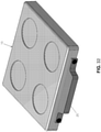
- FIG. 22 and 23 show one possible configuration for qualifying ball plate 55
- Figs. 24 and 25 show another possible configuration for qualifying ball plate 55.
- the removable qualifying ball plate 55 preferably comprises a rounded end 60 on one end and a male projection 25 on its other end, where male projection 25 allows removable qualifying ball plate 55 to be secured to another element of modular fixture plate system 5 (i.e., an interlocking fixture plate 10 or a docking plate 35).
- removable qualifying ball plate 55 may comprise a rounded end 60 on one end and a female recess 30 on its other end, where female recess 30 allows removable qualifying ball plate 55 to be secured to another element of modular fixture plate system 5 (i.e., an interlocking fixture plate 10 or a docking plate 35).
- the removable qualifying ball plate 55 is a precise tool which carries a qualifying ball 62 ( Figs. 26 and 27 ) which the probe of an inspection machine touches in order to register the inspection machine.
- qualifying ball 62 can be attached to removable qualifying ball plate 55 (e.g., to rounded end 60 of removable qualifying ball plate 55) such that qualifying ball 62 is upstanding from the plane of removable qualifying ball plate 55.
- This removable qualifying ball plate 55 will normally stay on the inspection machine's work surface while manufactured workpieces are inspected.
- This removable qualifying ball plate 55 is designed to accept the qualifying ball 62 (or the inspection machine test bar), provide an accurate surface for indicating with respect to the inspection machine probe, and can be moved out of the way quickly and easily when not in use.
- the surface area and work envelope of the inspection machine is completely free from obstructions and then has more useable space.
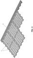
- interlocking fixture plates 10 The suggested material of all interlocking fixture plates 10 is half inch thick aluminum plate, however, the interlocking fixture plates can be manufactured in a variety of other metals or plastics (see Figs. 28-31 ) and can vary in thickness, overall size and geometry, with threaded, straight or tapered holes 32, with and without a subplate.
- the size of the interlocking fixture plates 10 is chosen based on the size and number of workpieces, and for the size of the machine work area.
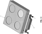
- Figs. 32 and 33 show another possible construction for interlocking fixture plates 10, wherein male projection 25 is manufactured separately from the remainder of interlocking fixture plate 10, and is added during the manufacturing process.
- This approach has the advantage that male projection 25 can be added to an existing fixture plate so as to make it usable with the present invention.
Landscapes
- Engineering & Computer Science (AREA)
- Mechanical Engineering (AREA)
- Automatic Assembly (AREA)
- General Engineering & Computer Science (AREA)
- Laser Beam Processing (AREA)
- Manufacture Or Reproduction Of Printing Formes (AREA)
Claims (15)
- Ein modulares Befestigungsplattensystem (5), umfassend:- eine Mehrzahl von zusammensteckbaren Befestigungsplatten (10), von denen jede eine Aufnahmefläche zur Aufnahme eines Werkstücks umfasst, das auf der zusammensteckbaren Befestigungsplatte (10) positioniert werden soll, sowie wenigstens ein Steck-Ende (15) und ein Einsteck-Ende (20), wobei das Steck-Ende (15) wenigstens einen Steck-Vorsprung (25) aufweist und das Einsteck-Ende (20) wenigstens eine Einsteck-Vertiefung (30); und- eine Andockplatte (35), umfassend wenigstens eines von dem wenigstens einen Steck-Vorsprung (25) und der wenigstens einen Einsteck-Vertiefung (30);- wobei der wenigstens eine Steck-Vorsprung (25) oder die wenigstens eine Einsteck-Vertiefung (30) der wenigstens einen zusammensteckbaren Befestigungsplatte (10) mit einem passenden von dem wenigstens einen Steck-Vorsprung (25) oder der wenigstens einen Einsteck-Vertiefung (30) der Andockplatte (35) ineinandergreift,- und wobei die zusammensteckbaren Befestigungsplatten (10) zusammenpassen, um gemeinsam die gewünschte Gesamtgröße der Befestigungsplatte zu erzeugen,dadurch gekennzeichnet, dass die zusammensteckbaren Befestigungsplatten (10) eine Mehrzahl von darin ausgebildeten Gewindebohrungen (32) aufweisen zur Aufnahme von Werkstückhalte-Elementen, welche das Werkstück auf der Aufnahmefläche der zusammensteckbaren Befestigungsplatte (10) halten.
- Ein modulares Befestigungsplattensystem (5) gemäß Anspruch 1, wobei wenigstens eine zusammensteckbare Befestigungsplatte (10) ein Steck-Ende (15) und ein Einsteck-Ende (20) umfasst.
- Ein modulares Befestigungsplattensystem (5) gemäß Anspruch 1, wobei das Steck-Ende (15) eine Mehrzahl von Steck-Vorsprüngen (25) aufweist.
- Ein modulares Befestigungsplattensystem (5) gemäß Anspruch 1, wobei das Einsteck-Ende (20) eine Mehrzahl von Einsteck-Vertiefungen (30) aufweist.
- Ein modulares Befestigungsplattensystem (5) gemäß Anspruch 1, wobei die Andockplatte (35) wenigstens einen Steck-Vorsprung (25) aufweist.
- Ein modulares Befestigungsplattensystem (5) gemäß Anspruch 1, wobei die Andockplatte (35) eine Mehrzahl von Steck-Vorsprüngen (25) aufweist.
- Ein modulares Befestigungsplattensystem (5) gemäß Anspruch 1, wobei die Andockplatte (35) wenigstens eine Einsteck-Vertiefung (30) aufweist.
- Ein modulares Befestigungsplattensystem (5) gemäß Anspruch 1, wobei die Andockplatte (35) eine Mehrzahl von Einsteck-Vertiefungen (30) aufweist.
- Ein modulares Befestigungsplattensystem (5) gemäß Anspruch 1, umfasssend eine Mehrzahl von Andockplatten (35).
- Ein modulares Befestigungsplattensystem (5) gemäß einem der vorhergehenden Ansprüche, wobei die Mehrzahl von Gewindebohrungen (32) in einem regelmäßigen Muster angeordnet ist.
- Ein modulares Befestigungsplattensystem (5) gemäß Anspruch 1, ferner umfassend wenigstens einen Magnet (45), der an wenigstens einem Teil von der wenigstens einen, zusammensteckbaren Befestigungsplatte (10) und der Andockplatte (35) angeordnet ist.
- Ein modulares Befestigungsplattensystem (5) gemäß Anspruch 11, ferner umfassend wenigstens einen Magnet (45), der an wenigstens einer zusammensteckbaren Befestigungsplatte (10) angeordnet ist, und wenigstens einen Magnet (45), der an der Andockplatte (35) angeordnet ist.
- Ein modulares Befestigungsplattensystem (5) gemäß Anspruch 1, ferner umfassend eine Basisplatte (50) zur Befestigung an einer Maschine, wobei die Basisplatte (50) dazu ausgelegt ist, wenigstens eine zusammensteckbaren Befestigungsplatte (10) und die Andockplatte (35) aufzunehmen.
- Ein modulares Befestigungsplattensystem (5) gemäß Anspruch 1, wobei wenigstens ein Steck-Vorsprung (25) und wenigstens eine Einsteck-Vertiefung (30) als Schwalbenschwanz-Anordnung ausgebildet ist.
- Ein Verfahren zur Positionierung eines Werkstücks während eines Fertigungs- und/oder Prüfungsverfahrens, gekennzeichnet durch die folgenden Schritte:- Bereitstellen eines modularen Befestigungsplattensystems (5) gemäß einem der vorhergehenden Ansprüche;- Zusammenstecken von wenigstens einem Steck-Vorsprung (25) oder einer Einsteck-Vertiefung (30) von wenigstens einer zusammensteckbaren Befestigungsplatte (10) mit einem passenden Teil von wenigstens einem Steck-Vorsprung (25) oder von wenigstens einer Einsteck-Vertiefung (30) der Andockplatte (35), um wenigstens eine zusammensteckbare Befestigungsplatte (10) relativ zu der Andockplatte (35) zu stabilisieren; und Positionieren eines Werkstücks auf de wenigstens einen zusammensteckbaren Befestigungsplatte (10).
Applications Claiming Priority (3)
| Application Number | Priority Date | Filing Date | Title |
|---|---|---|---|
| US201361771575P | 2013-03-01 | 2013-03-01 | |
| US201361825846P | 2013-05-21 | 2013-05-21 | |
| PCT/US2014/019984 WO2014134613A1 (en) | 2013-03-01 | 2014-03-03 | Modular fixture plate system for positioning a workpiece during a manufacturing and/or inspection process |
Publications (4)
| Publication Number | Publication Date |
|---|---|
| EP2961504A1 EP2961504A1 (de) | 2016-01-06 |
| EP2961504A4 EP2961504A4 (de) | 2016-12-07 |
| EP2961504B1 EP2961504B1 (de) | 2018-11-28 |
| EP2961504B2 true EP2961504B2 (de) | 2022-03-09 |
Family
ID=51421016
Family Applications (1)
| Application Number | Title | Priority Date | Filing Date |
|---|---|---|---|
| EP14757128.5A Active EP2961504B2 (de) | 2013-03-01 | 2014-03-03 | Modulares befestigungsplattensystem zum positionieren eines werkstücks während eines fertigungs- und/oder prüfverfahrens |
Country Status (3)
| Country | Link |
|---|---|
| US (4) | US10183380B2 (de) |
| EP (1) | EP2961504B2 (de) |
| WO (1) | WO2014134613A1 (de) |
Families Citing this family (12)
| Publication number | Priority date | Publication date | Assignee | Title |
|---|---|---|---|---|
| US10183380B2 (en) * | 2013-03-01 | 2019-01-22 | Steven E. Phillips | Modular fixture plate system for positioning a workpiece during a manufacturing and/or inspection process |
| US9060460B1 (en) * | 2013-03-15 | 2015-06-16 | Frozencpu.Com | Computer and electronics assembly mat |
| US9874307B1 (en) * | 2016-07-13 | 2018-01-23 | Nestor Del Castillo | Portable stand system with two plaques |
| US11287223B2 (en) * | 2017-09-30 | 2022-03-29 | Robert E. Stewart | Mounting and fastening system mounting adapter |
| US20190380543A1 (en) * | 2018-06-15 | 2019-12-19 | Prateek N. Bhargava | Modular cutting board and accessories |
| US10739382B2 (en) | 2018-09-18 | 2020-08-11 | Keysight Technologies, Inc. | Testing apparatus having a configurable probe fixture |
| TR201921447A1 (tr) * | 2019-12-25 | 2021-07-26 | Aselsan Elektronik Sanayi Ve Ticaret As | Manyetik modüler fisktür sistemi ve yöntemi |
| IL272024B (en) * | 2020-01-14 | 2021-02-28 | Emi Integrated Systems Ltd | Modular self-configuring industrial table |
| CN111469075B (zh) * | 2020-05-18 | 2024-07-02 | 佛山市顺德区新马木工机械设备有限公司 | 一种多工位多角度加工系统 |
| US11969847B2 (en) | 2021-05-19 | 2024-04-30 | Metrologyworks, Inc. | Modular fixture plate alignment system |
| USD1068880S1 (en) * | 2022-09-21 | 2025-04-01 | Develop Llc | Vacuum fixture plate |
| CN120112410A (zh) * | 2022-10-27 | 2025-06-06 | 麦格纳国际公司 | 模块化坯件模具组件和/或检查固定组件 |
Citations (6)
| Publication number | Priority date | Publication date | Assignee | Title |
|---|---|---|---|---|
| US4805887A (en) † | 1987-11-12 | 1989-02-21 | Rayco Manufacturing, Inc. | Universal vacuum and clamp setup fixture for coordinate measuring machines |
| US5809905A (en) † | 1995-09-05 | 1998-09-22 | Plastic Pallet Production, Inc. | Vertical interlocking modular pallet apparatus and method of construction |
| WO2006129264A1 (en) † | 2005-05-31 | 2006-12-07 | Tofas Turk Otomobil Fabrikasi Anonim Sirketi | A modular positioning structure |
| EP2103537A1 (de) † | 2008-03-14 | 2009-09-23 | Rehrig Pacific Company | Stützplattform |
| US20100299945A1 (en) † | 2009-06-02 | 2010-12-02 | James Richard Lacy | System and method for workpiece coordinate measurements |
| EP2417871A1 (de) † | 2009-04-06 | 2012-02-15 | Jung, Jae-Weon | Tragbare montageflachbank |
Family Cites Families (18)
| Publication number | Priority date | Publication date | Assignee | Title |
|---|---|---|---|---|
| US1571092A (en) * | 1925-07-20 | 1926-01-26 | Lally John | Connection for building columns |
| US1894061A (en) | 1931-04-08 | 1933-01-10 | Reginald E Sanders | Toy construction block |
| US3512324A (en) * | 1968-04-22 | 1970-05-19 | Lola L Reed | Portable sectional floor |
| AT301301B (de) * | 1971-02-24 | 1972-08-25 | Ver Flugtechnische Werke | Aufspannplatte für Werkzeugmaschinen |
| US5064321A (en) | 1990-07-03 | 1991-11-12 | Barnes Gary D | Tooling plate |
| US5052158A (en) * | 1990-07-13 | 1991-10-01 | Foam Design Consumer Products, Inc. | Modular locking floor covering |
| JP3673117B2 (ja) * | 1999-06-14 | 2005-07-20 | 和泉電気株式会社 | 組立装置とそのためのトレイシステム |
| US6431936B1 (en) * | 2000-04-28 | 2002-08-13 | People Co., Ltd. | Building toy |
| US6431963B1 (en) | 2000-10-04 | 2002-08-13 | Richard L. Delmoro | Tire uniformity machine grinder |
| DE202009010082U1 (de) | 2009-07-25 | 2009-10-08 | Hahn, Alexander | Gehrungs-Eckpositionierhilfe |
| EP2292381A1 (de) | 2009-09-02 | 2011-03-09 | System 3R Schweiz AG | Spannsystem für Werkstücke |
| WO2011064349A1 (de) * | 2009-11-27 | 2011-06-03 | Micado Cad-Solutions Gmbh | Modulare haltevorrichtung |
| EP2525881A4 (de) * | 2010-01-22 | 2015-09-09 | Connor Sport Court International Inc | Modulares unterbodensystem |
| US8881482B2 (en) * | 2010-01-22 | 2014-11-11 | Connor Sport Court International, Llc | Modular flooring system |
| CA2811915C (en) * | 2010-09-30 | 2017-07-04 | Fcs System Srl | Modular structure for supporting blanks |
| US10183380B2 (en) * | 2013-03-01 | 2019-01-22 | Steven E. Phillips | Modular fixture plate system for positioning a workpiece during a manufacturing and/or inspection process |
| US9636793B2 (en) * | 2013-10-04 | 2017-05-02 | John Morgan | Part fixturing device with adjustable positioning |
| US11969847B2 (en) | 2021-05-19 | 2024-04-30 | Metrologyworks, Inc. | Modular fixture plate alignment system |
-
2014
- 2014-03-03 US US14/195,607 patent/US10183380B2/en active Active
- 2014-03-03 WO PCT/US2014/019984 patent/WO2014134613A1/en not_active Ceased
- 2014-03-03 EP EP14757128.5A patent/EP2961504B2/de active Active
-
2019
- 2019-01-18 US US16/251,923 patent/US11458597B2/en active Active
-
2022
- 2022-10-04 US US17/959,563 patent/US12097594B2/en active Active
-
2024
- 2024-09-24 US US18/894,163 patent/US20250187148A1/en active Pending
Patent Citations (6)
| Publication number | Priority date | Publication date | Assignee | Title |
|---|---|---|---|---|
| US4805887A (en) † | 1987-11-12 | 1989-02-21 | Rayco Manufacturing, Inc. | Universal vacuum and clamp setup fixture for coordinate measuring machines |
| US5809905A (en) † | 1995-09-05 | 1998-09-22 | Plastic Pallet Production, Inc. | Vertical interlocking modular pallet apparatus and method of construction |
| WO2006129264A1 (en) † | 2005-05-31 | 2006-12-07 | Tofas Turk Otomobil Fabrikasi Anonim Sirketi | A modular positioning structure |
| EP2103537A1 (de) † | 2008-03-14 | 2009-09-23 | Rehrig Pacific Company | Stützplattform |
| EP2417871A1 (de) † | 2009-04-06 | 2012-02-15 | Jung, Jae-Weon | Tragbare montageflachbank |
| US20100299945A1 (en) † | 2009-06-02 | 2010-12-02 | James Richard Lacy | System and method for workpiece coordinate measurements |
Also Published As
| Publication number | Publication date |
|---|---|
| US20140248113A1 (en) | 2014-09-04 |
| US10183380B2 (en) | 2019-01-22 |
| EP2961504A4 (de) | 2016-12-07 |
| US12097594B2 (en) | 2024-09-24 |
| US20190381634A1 (en) | 2019-12-19 |
| US11458597B2 (en) | 2022-10-04 |
| EP2961504B1 (de) | 2018-11-28 |
| EP2961504A1 (de) | 2016-01-06 |
| WO2014134613A1 (en) | 2014-09-04 |
| US20250187148A1 (en) | 2025-06-12 |
| US20230140513A1 (en) | 2023-05-04 |
Similar Documents
| Publication | Publication Date | Title |
|---|---|---|
| US12097594B2 (en) | Modular fixture plate system for positioning a workpiece during a manufacturing and/or inspection process | |
| JP4671599B2 (ja) | ツーリング装置を用いる製造セル | |
| US4630811A (en) | Modular fixturing apparatus | |
| KR20110111290A (ko) | 가공물을 정확히 고정된 위치에 지지시키기 위한 자기 클램핑 장치 | |
| JP3988986B2 (ja) | 精密バイス | |
| CN103894853A (zh) | 一种适用在多种加工设备上装夹塑胶模具的通用夹具 | |
| CN106826331A (zh) | 定位夹具 | |
| KR101467290B1 (ko) | 충격시편 절단용 지그 및 이를 활용한 충격시편 절단방법 | |
| JP6297339B2 (ja) | 打刻装置 | |
| KR20140032105A (ko) | 드릴링 가공 지그 | |
| CN212398231U (zh) | 一种定位制孔装置 | |
| KR101214110B1 (ko) | 충격시험편의 홈 가공용 지그 | |
| JP5163785B2 (ja) | カム装置の工具取付け面に加工工具を固定するための方法及びカム装置を具備したプレス金型装置の製造方法 | |
| JP5096717B2 (ja) | ワーク取付具及びワークの加工方法 | |
| CN102355971A (zh) | 用于制造设备的可拆卸固定装置 | |
| CN217371418U (zh) | Cnc机床夹具快速定位装置 | |
| Kršulja et al. | Assembly setup for modular fixture machining process | |
| JPS61111870A (ja) | 対象物を保持するための装置 | |
| JP5089438B2 (ja) | 工具ホルダの取付ナット及び工具ホルダの取付構造 | |
| KR101578084B1 (ko) | 바이스용 평행 지지블럭 | |
| CN103831637B (zh) | 细杆状工件夹具 | |
| KR101401268B1 (ko) | 다이캐스팅 핸들의 교체식 가공장치 | |
| CN217122521U (zh) | 应用于多工序的定位夹持装置 | |
| KR20190138102A (ko) | 치공구 스탠드 | |
| CN217570965U (zh) | 一种铁路电动转辙机销钉架的钻孔加工装置 |
Legal Events
| Date | Code | Title | Description |
|---|---|---|---|
| PUAI | Public reference made under article 153(3) epc to a published international application that has entered the european phase |
Free format text: ORIGINAL CODE: 0009012 |
|
| 17P | Request for examination filed |
Effective date: 20150929 |
|
| AK | Designated contracting states |
Kind code of ref document: A1 Designated state(s): AL AT BE BG CH CY CZ DE DK EE ES FI FR GB GR HR HU IE IS IT LI LT LU LV MC MK MT NL NO PL PT RO RS SE SI SK SM TR |
|
| AX | Request for extension of the european patent |
Extension state: BA ME |
|
| DAX | Request for extension of the european patent (deleted) | ||
| A4 | Supplementary search report drawn up and despatched |
Effective date: 20161104 |
|
| RIC1 | Information provided on ipc code assigned before grant |
Ipc: B23Q 1/03 20060101ALI20161028BHEP Ipc: A63H 33/08 20060101AFI20161028BHEP Ipc: B25B 11/00 20060101ALI20161028BHEP Ipc: B23Q 3/02 20060101ALI20161028BHEP Ipc: B23Q 37/00 20060101ALI20161028BHEP |
|
| GRAP | Despatch of communication of intention to grant a patent |
Free format text: ORIGINAL CODE: EPIDOSNIGR1 |
|
| STAA | Information on the status of an ep patent application or granted ep patent |
Free format text: STATUS: GRANT OF PATENT IS INTENDED |
|
| INTG | Intention to grant announced |
Effective date: 20180607 |
|
| GRAS | Grant fee paid |
Free format text: ORIGINAL CODE: EPIDOSNIGR3 |
|
| GRAA | (expected) grant |
Free format text: ORIGINAL CODE: 0009210 |
|
| STAA | Information on the status of an ep patent application or granted ep patent |
Free format text: STATUS: THE PATENT HAS BEEN GRANTED |
|
| AK | Designated contracting states |
Kind code of ref document: B1 Designated state(s): AL AT BE BG CH CY CZ DE DK EE ES FI FR GB GR HR HU IE IS IT LI LT LU LV MC MK MT NL NO PL PT RO RS SE SI SK SM TR |
|
| REG | Reference to a national code |
Ref country code: CH Ref legal event code: EP |
|
| REG | Reference to a national code |
Ref country code: DE Ref legal event code: R096 Ref document number: 602014036972 Country of ref document: DE |
|
| REG | Reference to a national code |
Ref country code: AT Ref legal event code: REF Ref document number: 1069562 Country of ref document: AT Kind code of ref document: T Effective date: 20181215 |
|
| REG | Reference to a national code |
Ref country code: IE Ref legal event code: FG4D |
|
| REG | Reference to a national code |
Ref country code: NL Ref legal event code: MP Effective date: 20181128 |
|
| REG | Reference to a national code |
Ref country code: LT Ref legal event code: MG4D |
|
| REG | Reference to a national code |
Ref country code: AT Ref legal event code: MK05 Ref document number: 1069562 Country of ref document: AT Kind code of ref document: T Effective date: 20181128 |
|
| PG25 | Lapsed in a contracting state [announced via postgrant information from national office to epo] |
Ref country code: BG Free format text: LAPSE BECAUSE OF FAILURE TO SUBMIT A TRANSLATION OF THE DESCRIPTION OR TO PAY THE FEE WITHIN THE PRESCRIBED TIME-LIMIT Effective date: 20190228 Ref country code: IS Free format text: LAPSE BECAUSE OF FAILURE TO SUBMIT A TRANSLATION OF THE DESCRIPTION OR TO PAY THE FEE WITHIN THE PRESCRIBED TIME-LIMIT Effective date: 20190328 Ref country code: HR Free format text: LAPSE BECAUSE OF FAILURE TO SUBMIT A TRANSLATION OF THE DESCRIPTION OR TO PAY THE FEE WITHIN THE PRESCRIBED TIME-LIMIT Effective date: 20181128 Ref country code: NO Free format text: LAPSE BECAUSE OF FAILURE TO SUBMIT A TRANSLATION OF THE DESCRIPTION OR TO PAY THE FEE WITHIN THE PRESCRIBED TIME-LIMIT Effective date: 20190228 Ref country code: ES Free format text: LAPSE BECAUSE OF FAILURE TO SUBMIT A TRANSLATION OF THE DESCRIPTION OR TO PAY THE FEE WITHIN THE PRESCRIBED TIME-LIMIT Effective date: 20181128 Ref country code: LT Free format text: LAPSE BECAUSE OF FAILURE TO SUBMIT A TRANSLATION OF THE DESCRIPTION OR TO PAY THE FEE WITHIN THE PRESCRIBED TIME-LIMIT Effective date: 20181128 Ref country code: AT Free format text: LAPSE BECAUSE OF FAILURE TO SUBMIT A TRANSLATION OF THE DESCRIPTION OR TO PAY THE FEE WITHIN THE PRESCRIBED TIME-LIMIT Effective date: 20181128 Ref country code: LV Free format text: LAPSE BECAUSE OF FAILURE TO SUBMIT A TRANSLATION OF THE DESCRIPTION OR TO PAY THE FEE WITHIN THE PRESCRIBED TIME-LIMIT Effective date: 20181128 Ref country code: FI Free format text: LAPSE BECAUSE OF FAILURE TO SUBMIT A TRANSLATION OF THE DESCRIPTION OR TO PAY THE FEE WITHIN THE PRESCRIBED TIME-LIMIT Effective date: 20181128 |
|
| PG25 | Lapsed in a contracting state [announced via postgrant information from national office to epo] |
Ref country code: GR Free format text: LAPSE BECAUSE OF FAILURE TO SUBMIT A TRANSLATION OF THE DESCRIPTION OR TO PAY THE FEE WITHIN THE PRESCRIBED TIME-LIMIT Effective date: 20190301 Ref country code: AL Free format text: LAPSE BECAUSE OF FAILURE TO SUBMIT A TRANSLATION OF THE DESCRIPTION OR TO PAY THE FEE WITHIN THE PRESCRIBED TIME-LIMIT Effective date: 20181128 Ref country code: RS Free format text: LAPSE BECAUSE OF FAILURE TO SUBMIT A TRANSLATION OF THE DESCRIPTION OR TO PAY THE FEE WITHIN THE PRESCRIBED TIME-LIMIT Effective date: 20181128 Ref country code: SE Free format text: LAPSE BECAUSE OF FAILURE TO SUBMIT A TRANSLATION OF THE DESCRIPTION OR TO PAY THE FEE WITHIN THE PRESCRIBED TIME-LIMIT Effective date: 20181128 Ref country code: PT Free format text: LAPSE BECAUSE OF FAILURE TO SUBMIT A TRANSLATION OF THE DESCRIPTION OR TO PAY THE FEE WITHIN THE PRESCRIBED TIME-LIMIT Effective date: 20190328 |
|
| PG25 | Lapsed in a contracting state [announced via postgrant information from national office to epo] |
Ref country code: NL Free format text: LAPSE BECAUSE OF FAILURE TO SUBMIT A TRANSLATION OF THE DESCRIPTION OR TO PAY THE FEE WITHIN THE PRESCRIBED TIME-LIMIT Effective date: 20181128 |
|
| PG25 | Lapsed in a contracting state [announced via postgrant information from national office to epo] |
Ref country code: DK Free format text: LAPSE BECAUSE OF FAILURE TO SUBMIT A TRANSLATION OF THE DESCRIPTION OR TO PAY THE FEE WITHIN THE PRESCRIBED TIME-LIMIT Effective date: 20181128 Ref country code: IT Free format text: LAPSE BECAUSE OF FAILURE TO SUBMIT A TRANSLATION OF THE DESCRIPTION OR TO PAY THE FEE WITHIN THE PRESCRIBED TIME-LIMIT Effective date: 20181128 Ref country code: CZ Free format text: LAPSE BECAUSE OF FAILURE TO SUBMIT A TRANSLATION OF THE DESCRIPTION OR TO PAY THE FEE WITHIN THE PRESCRIBED TIME-LIMIT Effective date: 20181128 Ref country code: PL Free format text: LAPSE BECAUSE OF FAILURE TO SUBMIT A TRANSLATION OF THE DESCRIPTION OR TO PAY THE FEE WITHIN THE PRESCRIBED TIME-LIMIT Effective date: 20181128 |
|
| REG | Reference to a national code |
Ref country code: DE Ref legal event code: R026 Ref document number: 602014036972 Country of ref document: DE |
|
| PG25 | Lapsed in a contracting state [announced via postgrant information from national office to epo] |
Ref country code: RO Free format text: LAPSE BECAUSE OF FAILURE TO SUBMIT A TRANSLATION OF THE DESCRIPTION OR TO PAY THE FEE WITHIN THE PRESCRIBED TIME-LIMIT Effective date: 20181128 Ref country code: SK Free format text: LAPSE BECAUSE OF FAILURE TO SUBMIT A TRANSLATION OF THE DESCRIPTION OR TO PAY THE FEE WITHIN THE PRESCRIBED TIME-LIMIT Effective date: 20181128 Ref country code: EE Free format text: LAPSE BECAUSE OF FAILURE TO SUBMIT A TRANSLATION OF THE DESCRIPTION OR TO PAY THE FEE WITHIN THE PRESCRIBED TIME-LIMIT Effective date: 20181128 Ref country code: SM Free format text: LAPSE BECAUSE OF FAILURE TO SUBMIT A TRANSLATION OF THE DESCRIPTION OR TO PAY THE FEE WITHIN THE PRESCRIBED TIME-LIMIT Effective date: 20181128 |
|
| PLBI | Opposition filed |
Free format text: ORIGINAL CODE: 0009260 |
|
| PLAX | Notice of opposition and request to file observation + time limit sent |
Free format text: ORIGINAL CODE: EPIDOSNOBS2 |
|
| 26 | Opposition filed |
Opponent name: RENISHAW PLC Effective date: 20190822 |
|
| PG25 | Lapsed in a contracting state [announced via postgrant information from national office to epo] |
Ref country code: SI Free format text: LAPSE BECAUSE OF FAILURE TO SUBMIT A TRANSLATION OF THE DESCRIPTION OR TO PAY THE FEE WITHIN THE PRESCRIBED TIME-LIMIT Effective date: 20181128 Ref country code: MC Free format text: LAPSE BECAUSE OF FAILURE TO SUBMIT A TRANSLATION OF THE DESCRIPTION OR TO PAY THE FEE WITHIN THE PRESCRIBED TIME-LIMIT Effective date: 20181128 |
|
| REG | Reference to a national code |
Ref country code: CH Ref legal event code: PL |
|
| PG25 | Lapsed in a contracting state [announced via postgrant information from national office to epo] |
Ref country code: LU Free format text: LAPSE BECAUSE OF NON-PAYMENT OF DUE FEES Effective date: 20190303 |
|
| REG | Reference to a national code |
Ref country code: BE Ref legal event code: MM Effective date: 20190331 |
|
| PLBB | Reply of patent proprietor to notice(s) of opposition received |
Free format text: ORIGINAL CODE: EPIDOSNOBS3 |
|
| PG25 | Lapsed in a contracting state [announced via postgrant information from national office to epo] |
Ref country code: CH Free format text: LAPSE BECAUSE OF NON-PAYMENT OF DUE FEES Effective date: 20190331 Ref country code: IE Free format text: LAPSE BECAUSE OF NON-PAYMENT OF DUE FEES Effective date: 20190303 Ref country code: LI Free format text: LAPSE BECAUSE OF NON-PAYMENT OF DUE FEES Effective date: 20190331 |
|
| PG25 | Lapsed in a contracting state [announced via postgrant information from national office to epo] |
Ref country code: BE Free format text: LAPSE BECAUSE OF NON-PAYMENT OF DUE FEES Effective date: 20190331 |
|
| PG25 | Lapsed in a contracting state [announced via postgrant information from national office to epo] |
Ref country code: TR Free format text: LAPSE BECAUSE OF FAILURE TO SUBMIT A TRANSLATION OF THE DESCRIPTION OR TO PAY THE FEE WITHIN THE PRESCRIBED TIME-LIMIT Effective date: 20181128 |
|
| PG25 | Lapsed in a contracting state [announced via postgrant information from national office to epo] |
Ref country code: MT Free format text: LAPSE BECAUSE OF NON-PAYMENT OF DUE FEES Effective date: 20190303 |
|
| PLBP | Opposition withdrawn |
Free format text: ORIGINAL CODE: 0009264 |
|
| PG25 | Lapsed in a contracting state [announced via postgrant information from national office to epo] |
Ref country code: CY Free format text: LAPSE BECAUSE OF FAILURE TO SUBMIT A TRANSLATION OF THE DESCRIPTION OR TO PAY THE FEE WITHIN THE PRESCRIBED TIME-LIMIT Effective date: 20181128 |
|
| PG25 | Lapsed in a contracting state [announced via postgrant information from national office to epo] |
Ref country code: HU Free format text: LAPSE BECAUSE OF FAILURE TO SUBMIT A TRANSLATION OF THE DESCRIPTION OR TO PAY THE FEE WITHIN THE PRESCRIBED TIME-LIMIT; INVALID AB INITIO Effective date: 20140303 |
|
| PUAH | Patent maintained in amended form |
Free format text: ORIGINAL CODE: 0009272 |
|
| STAA | Information on the status of an ep patent application or granted ep patent |
Free format text: STATUS: PATENT MAINTAINED AS AMENDED |
|
| 27A | Patent maintained in amended form |
Effective date: 20220309 |
|
| AK | Designated contracting states |
Kind code of ref document: B2 Designated state(s): AL AT BE BG CH CY CZ DE DK EE ES FI FR GB GR HR HU IE IS IT LI LT LU LV MC MK MT NL NO PL PT RO RS SE SI SK SM TR |
|
| REG | Reference to a national code |
Ref country code: DE Ref legal event code: R102 Ref document number: 602014036972 Country of ref document: DE |
|
| PG25 | Lapsed in a contracting state [announced via postgrant information from national office to epo] |
Ref country code: MK Free format text: LAPSE BECAUSE OF FAILURE TO SUBMIT A TRANSLATION OF THE DESCRIPTION OR TO PAY THE FEE WITHIN THE PRESCRIBED TIME-LIMIT Effective date: 20181128 |
|
| P01 | Opt-out of the competence of the unified patent court (upc) registered |
Effective date: 20230527 |
|
| REG | Reference to a national code |
Ref country code: DE Ref legal event code: R081 Ref document number: 602014036972 Country of ref document: DE Owner name: WEYLAND GROUP LLC, BOYLSTON, US Free format text: FORMER OWNER: PHILLIPS, STEVEN E., BOYLSTON, MASS., US Ref country code: DE Ref legal event code: R081 Ref document number: 602014036972 Country of ref document: DE Owner name: PHILLIPS PRECISION, INC., BOYLSTON, US Free format text: FORMER OWNER: PHILLIPS, STEVEN E., BOYLSTON, MASS., US |
|
| REG | Reference to a national code |
Ref country code: DE Ref legal event code: R081 Ref document number: 602014036972 Country of ref document: DE Owner name: WEYLAND GROUP LLC, BOYLSTON, US Free format text: FORMER OWNER: PHILLIPS PRECISION, INC., BOYLSTON, MA, US |
|
| REG | Reference to a national code |
Ref country code: GB Ref legal event code: 732E Free format text: REGISTERED BETWEEN 20250327 AND 20250402 |
|
| PGFP | Annual fee paid to national office [announced via postgrant information from national office to epo] |
Ref country code: FR Payment date: 20250325 Year of fee payment: 12 |
|
| REG | Reference to a national code |
Ref country code: GB Ref legal event code: 732E Free format text: REGISTERED BETWEEN 20250626 AND 20250702 |
|
| PGFP | Annual fee paid to national office [announced via postgrant information from national office to epo] |
Ref country code: DE Payment date: 20250924 Year of fee payment: 12 |
|
| PGFP | Annual fee paid to national office [announced via postgrant information from national office to epo] |
Ref country code: GB Payment date: 20250924 Year of fee payment: 12 |