EP2961504B2 - Modular fixture plate system for positioning a workpiece during a manufacturing and/or inspection process - Google Patents
Modular fixture plate system for positioning a workpiece during a manufacturing and/or inspection process Download PDFInfo
- Publication number
- EP2961504B2 EP2961504B2 EP14757128.5A EP14757128A EP2961504B2 EP 2961504 B2 EP2961504 B2 EP 2961504B2 EP 14757128 A EP14757128 A EP 14757128A EP 2961504 B2 EP2961504 B2 EP 2961504B2
- Authority
- EP
- European Patent Office
- Prior art keywords
- plate
- interlocking
- fixture
- fixture plate
- docking
- Prior art date
- Legal status (The legal status is an assumption and is not a legal conclusion. Google has not performed a legal analysis and makes no representation as to the accuracy of the status listed.)
- Active
Links
Images


Classifications
-
- B—PERFORMING OPERATIONS; TRANSPORTING
- B25—HAND TOOLS; PORTABLE POWER-DRIVEN TOOLS; MANIPULATORS
- B25B—TOOLS OR BENCH DEVICES NOT OTHERWISE PROVIDED FOR, FOR FASTENING, CONNECTING, DISENGAGING, OR HOLDING
- B25B11/00—Work holders not covered by any preceding group in the subclass, e.g. magnetic work holders, vacuum work holders
-
- B—PERFORMING OPERATIONS; TRANSPORTING
- B23—MACHINE TOOLS; METAL-WORKING NOT OTHERWISE PROVIDED FOR
- B23Q—DETAILS, COMPONENTS, OR ACCESSORIES FOR MACHINE TOOLS, e.g. ARRANGEMENTS FOR COPYING OR CONTROLLING; MACHINE TOOLS IN GENERAL CHARACTERISED BY THE CONSTRUCTION OF PARTICULAR DETAILS OR COMPONENTS; COMBINATIONS OR ASSOCIATIONS OF METAL-WORKING MACHINES, NOT DIRECTED TO A PARTICULAR RESULT
- B23Q1/00—Members which are comprised in the general build-up of a form of machine, particularly relatively large fixed members
- B23Q1/03—Stationary work or tool supports
-
- B—PERFORMING OPERATIONS; TRANSPORTING
- B23—MACHINE TOOLS; METAL-WORKING NOT OTHERWISE PROVIDED FOR
- B23Q—DETAILS, COMPONENTS, OR ACCESSORIES FOR MACHINE TOOLS, e.g. ARRANGEMENTS FOR COPYING OR CONTROLLING; MACHINE TOOLS IN GENERAL CHARACTERISED BY THE CONSTRUCTION OF PARTICULAR DETAILS OR COMPONENTS; COMBINATIONS OR ASSOCIATIONS OF METAL-WORKING MACHINES, NOT DIRECTED TO A PARTICULAR RESULT
- B23Q3/00—Devices holding, supporting, or positioning work or tools, of a kind normally removable from the machine
- B23Q3/02—Devices holding, supporting, or positioning work or tools, of a kind normally removable from the machine for mounting on a work-table, tool-slide, or analogous part
-
- B—PERFORMING OPERATIONS; TRANSPORTING
- B23—MACHINE TOOLS; METAL-WORKING NOT OTHERWISE PROVIDED FOR
- B23Q—DETAILS, COMPONENTS, OR ACCESSORIES FOR MACHINE TOOLS, e.g. ARRANGEMENTS FOR COPYING OR CONTROLLING; MACHINE TOOLS IN GENERAL CHARACTERISED BY THE CONSTRUCTION OF PARTICULAR DETAILS OR COMPONENTS; COMBINATIONS OR ASSOCIATIONS OF METAL-WORKING MACHINES, NOT DIRECTED TO A PARTICULAR RESULT
- B23Q37/00—Metal-working machines, or constructional combinations thereof, built-up from units designed so that at least some of the units can form parts of different machines or combinations; Units therefor in so far as the feature of interchangeability is important
- B23Q37/005—Modular base frames
Definitions
- This invention relates to methods and apparatus for manufacturing and/or inspection processes, and more particularly to methods and apparatus for positioning a workpiece during a manufacturing and/or inspection process.
- processes such as quality inspection, laser marking and etching, fiber laser and laser machining, dot peen marking, pad printing and routing all require accurate, repeatable positioning of a workpiece.
- a workpiece is typically held in a specific position while work is performed on the workpiece, and then the workpiece is "swapped out" for a new workpiece which is to be worked on.
- This new workpiece generally needs to be placed in the same, repeatable position as the preceding workpiece in order for the work process to be performed accurately.
- metal and/or plastic fixture plates are typically affixed to inspection machines to facilitate the quality inspection of previously-manufactured workpieces (i.e., to test the correctness of the manufactured workpieces).
- These fixture plates generally comprise a pattern of threaded holes formed therein which accept workpiece-holding elements such as screws, clamps, magnets, hold-downs, etc.
- workpiece-holding elements such as screws, clamps, magnets, hold-downs, etc
- the previously-manufactured workpiece is placed on these metal and/or plastic fixture plates, held down with the workpiece-holding elements and then the previously-manufactured workpiece is measured for correctness. Once the workpiece on the fixture plate has been inspected, the workpiece is replaced by another workpiece which is to be inspected using the same inspection set-up, fixture plates, etc.
- fixture plates are currently a one-piece design and are made to fit the workbed area of a particular inspection machine.
- different sizes of fixture plates must be provided for different inspection machines, thereby presenting an inventory issue or requiring long lead-times to custom manufacture fixture plates.
- workpieces vary in size and, in many cases, a workpiece may be relatively small and take up only a small fraction of the complete surface area of the fixture plate provided for a given inspection machine. In this case, the remainder of the fixture plate is essentially unused during the quality inspection process.
- these "light duty" manufacturing machines In a manner similar to a quality inspection machine, these "light duty" manufacturing machines generally have a work surface on which the workpiece is supported during processing.
- the laser etching of part numbers on workpieces is a very common practice.
- logo's, bar codes and/or other markings are also routinely added to workpieces.
- EP 2 292 381 A1 discloses a clamping system for fixing workpieces, comprising a stop element, at least two cantilevers and at least one clamping bracket, wherein in the stop element, in the cantilevers and in the clamping bracket, means are provided for the positive-locking, screwless connection of the stop element to the cantilevers on the one hand, and for connecting of the cantilevers to the clamping bracket on the other hand, for the creation of a stable frame. None of the relevant parts of such clamping system has a plate-like shape.
- US 5 052 158 A discloses a modular locking floor covering.
- the present invention provides a new and improved fixture plate system for positioning a workpiece during a quality inspection process and/or "light duty" manufacturing process, wherein the improved fixture plate system uses a modular approach to allow for the creation of simple but effective fixture assemblies that can provide fast, easy and repeatable setups for a specific production run.
- the present invention provides a new and improved fixture plate system for positioning a workpiece during a quality inspection process and/or "light duty" manufacturing process, wherein the improved fixture plate system uses a modular approach to allow for the creation of simple but effective fixture assemblies that can provide fast, easy and repeatable setups for a specific production run.
- the present invention comprises a new modular fixture plate system which allows for, and encourages, lean manufacturing principles for, but not limited to, quality inspection processes and "light duty" manufacturing processes such as laser marking and etching, fiber laser and laser machining, dot peen marking, pad printing and routing processes. More particularly, the present invention comprises a modular fixture plate system which comprises a plurality of interlocking plates which are selected, and then assembled together, so as to form a complete fixture plate, or which can be used individually so as to allow a portion of the workbed area of the inspection or manufacturing machine to be exposed, with the specific interlocking plates used being selected according to the size of the workpiece which is to be held, so that only those interlocking plates are used which are required to hold the workpiece of interest.
- a workpiece may be set up and programmed for inspection or working on a single interlocking plate, which can then be easily positioned on the inspection or manufacturing machine, the workpiece inspected or worked, then the workpiece and interlocking plate may be removed as a unit from the workbed of the inspection or manufacturing machine and thereafter be replaced by another workpiece and interlocking plate.
- the new modular fixture plate system of the present invention encourages inspectors and machine operators to employ lean manufacturing principles in the inspection and "light duty” manufacturing processes, using the minimum resources required, and enhances the value and investment of the inspection and "light duty” manufacturing equipment.
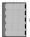
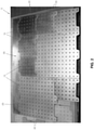
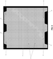
- Modular plate system 5 generally comprises one or more interlocking fixture plates 10 which are intended to be positioned on the workbed 12 of an inspection or "light duty" manufacturing machine.
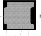
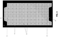
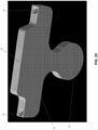
- Each interlocking fixture plate 10 comprises a male end 15 and a female end 20, wherein male end 15 comprises at least one male projection 25 and female end 20 comprises at least one female recess 30.
- the interlocking fixture plates 10 comprise a plurality of threaded holes 32, preferably disposed in a regular pattern, for accepting workpiece-holding elements well known in the art, e.g., screws, clamps, magnets, hold-downs, etc.
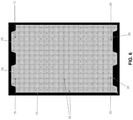
- interlocking fixture plates 10 can be formed in a variety of configurations, each with one or more male projections 25 and one or more female recesses 30.
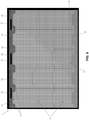
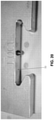
- Modular plate system 5 also comprises a docking plate 35 ( Figs. 1 , 2 , 7 and 8 ) which is intended to be affixed to the workbed of the inspection or "light duty" manufacturing machine, e.g., using an adhesive in which case the docking plate may comprise a solid structure ( Figs. 1 and 2 ) or using bolts which extend through counterbored slots 40 formed in docking plate 35 ( Figs. 7 and 8 ).
- Docking plate 35 comprises a plurality of female recesses 30 ( Figs.
- LOCs also sometimes referred to herein as "Locations” or “LOCs”, which receive male projections 25 of one or more interlocking fixture plates 10 or, alternatively, docking plate 35 comprises a plurality of male projections 25 for projecting into female recesses 30 of one or more interlocking fixture plates 10 ( Fig. 9 ) .
- Docking plate 35 and the various interlocking fixture plates 10 are designed to fit tightly together in an interlocked manner, with a male projection 25 of one element being received in a female recess 30 of another element.
- docking plate 35 comprises a plurality of female recesses 30 ( Figs. 1 , 2 and 9 )
- a plurality of interlocking fixture plates 10 may be interlocked with docking plate 35, and also with one another, by projecting the male projections 25 of some of the interlocking fixture plates 10 into the female recesses 30 of docking plate 35 and by projecting the male projections 25 of others of the interlocking fixture plates 10 into the female recesses 30 of the interlocking fixture plates 10 interlocked with docking plate 35.
- a docking plate 35 having a plurality of male projections 25 may be interlocked with interlocking fixture plates 10 by projecting the male projections of docking plate 35 into the female recesses of interlocking fixture plates 10 ( Fig. 9 ).
- interlocking fixture plates 10 can be interlocked with one another, and with docking plate 35, so as to cover some or all of the workbed of an inspection or manufacturing machine, and a large workpiece can span a number of interlocked fixture plates 10.
- interlocking fixture plates 10 fit together (e.g., in the manner of a jigsaw puzzle) to collectively create the desired overall size for the fixture plate.
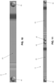
- docking plate 35 and the various interlocking fixture plates 10 are further secured to one another by magnets 45 which are disposed adjacent to male projections 25 of interlocking fixture plates 10 ( Figs. 10 and 11 ) and adjacent to female recesses 30 of interlocking fixture plates 10 ( Figs. 12 and 13 ), and by magnets 45 which are disposed adjacent to female recesses 30 of docking plate 35 ( Fig. 14 ) and adjacent to male projections 25 of docking plate 35 ( Figs. 15 and 16 ).
- magnets 45 are inset into docking plate 35 and interlocking fixture plates 10 so that the magnets of one plate mate with the magnets of an adjoining plate when a male projection 25 is received in a female recess 30.
- magnets 45 to secure docking plate 35 and interlocking fixture plates 10 to one another allow interlocking fixture plates 10 to be easily released from one another, and from docking plate 35, by hand and without the use of tools, whereby to enable interlocking fixture plates 10 to be quickly and easily swapped out as needed.
- a spring plunger set screw may be used to secure docking plate 35 and the various interlocking fixture plates 10 to one another.
- two or more docking plates 35 may be used in opposing arrangement ( Fig. 9 ) so as to lock the interlocking fixture plates 10 in position.
- modular fixture plate system 5 may also comprise a base plate 50 ( Fig. 17 ) on which the remainder of the system (e.g., docking plate 35 and one or more interlocking fixture plates 10) may be mounted.
- one preferred form of the invention may provide an interlocking fixture plate 10 which interlocks with only docking plate 35 ( Fig. 17 ), with the opposite end of interlocking fixture plate 10 being straight and with or without a handle or finger grip for easier removal of interlocking fixture plate 10.
- modular plate system 5 may provide docking plates 35 on all sides of interlocking fixture plates 10 so that the interlocking fixture plates 10 are interlocked, much like the pieces of a puzzle.
- the aforementioned magnets 45 can be omitted.
- male projections 25 and female recesses 30 may utilize a dovetail configuration ( Figs. 18-20 ).
- each of the interlocks of an interlocking fixture plate 10 with a docking plate 35 can be assigned a "Location” or “LOC” number (see Figs. 2 , 7 , 9 , 20 and 21 ). Inspection and manufacturing programs can be written and assigned to a specific "Location” or “LOC” number, i.e., to a specific location of an interlocking fixture plate 10 relative to docking plate 35.
- Programming inspection and manufacturing setups based on the interlocking fixture plate location or assignment allows for faster repeat setups and allows for more than one setup per machine (i.e., it permits work to be effected at LOCI, LOC2, LOC3, etc.), thereby speeding up the inspection and manufacturing processes.
- the hole pattern (i.e., the pattern of the holes 32 provided in interlocking fixture plates 10) is preferably consistent and seamless across all interlocking fixture plates 10 ( Fig. 1 and 2 ).
- a 1 ⁇ 4-20 or M6 threaded hole pattern with 1 inch spacing is shown in Figs. 1 and 2 .
- the described thread and hole pattern is typical of the industry, however, it can vary widely in thread size and hole spacing without departing from the scope of the present invention.
- interlocking fixture plates 10 can be created as "blanks" (i.e., without holes 32) so that the end user can then add the holes 32 in the sizes and/or patterns desired.
- FIG. 22 and 23 show one possible configuration for qualifying ball plate 55
- Figs. 24 and 25 show another possible configuration for qualifying ball plate 55.
- the removable qualifying ball plate 55 preferably comprises a rounded end 60 on one end and a male projection 25 on its other end, where male projection 25 allows removable qualifying ball plate 55 to be secured to another element of modular fixture plate system 5 (i.e., an interlocking fixture plate 10 or a docking plate 35).
- removable qualifying ball plate 55 may comprise a rounded end 60 on one end and a female recess 30 on its other end, where female recess 30 allows removable qualifying ball plate 55 to be secured to another element of modular fixture plate system 5 (i.e., an interlocking fixture plate 10 or a docking plate 35).
- the removable qualifying ball plate 55 is a precise tool which carries a qualifying ball 62 ( Figs. 26 and 27 ) which the probe of an inspection machine touches in order to register the inspection machine.
- qualifying ball 62 can be attached to removable qualifying ball plate 55 (e.g., to rounded end 60 of removable qualifying ball plate 55) such that qualifying ball 62 is upstanding from the plane of removable qualifying ball plate 55.
- This removable qualifying ball plate 55 will normally stay on the inspection machine's work surface while manufactured workpieces are inspected.
- This removable qualifying ball plate 55 is designed to accept the qualifying ball 62 (or the inspection machine test bar), provide an accurate surface for indicating with respect to the inspection machine probe, and can be moved out of the way quickly and easily when not in use.
- the surface area and work envelope of the inspection machine is completely free from obstructions and then has more useable space.
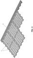
- interlocking fixture plates 10 The suggested material of all interlocking fixture plates 10 is half inch thick aluminum plate, however, the interlocking fixture plates can be manufactured in a variety of other metals or plastics (see Figs. 28-31 ) and can vary in thickness, overall size and geometry, with threaded, straight or tapered holes 32, with and without a subplate.
- the size of the interlocking fixture plates 10 is chosen based on the size and number of workpieces, and for the size of the machine work area.
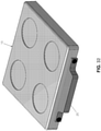
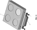
- Figs. 32 and 33 show another possible construction for interlocking fixture plates 10, wherein male projection 25 is manufactured separately from the remainder of interlocking fixture plate 10, and is added during the manufacturing process.
- This approach has the advantage that male projection 25 can be added to an existing fixture plate so as to make it usable with the present invention.
Landscapes
- Engineering & Computer Science (AREA)
- Mechanical Engineering (AREA)
- Automatic Assembly (AREA)
- Laser Beam Processing (AREA)
- General Engineering & Computer Science (AREA)
- Manufacture Or Reproduction Of Printing Formes (AREA)
Description
- This invention relates to methods and apparatus for manufacturing and/or inspection processes, and more particularly to methods and apparatus for positioning a workpiece during a manufacturing and/or inspection process.
- A number of manufacturing and/or inspection processes exist that require accurate, repeatable positioning of a workpiece. By way of example but not limitation, processes such as quality inspection, laser marking and etching, fiber laser and laser machining, dot peen marking, pad printing and routing all require accurate, repeatable positioning of a workpiece.
- During a manufacturing process, a workpiece is typically held in a specific position while work is performed on the workpiece, and then the workpiece is "swapped out" for a new workpiece which is to be worked on. This new workpiece generally needs to be placed in the same, repeatable position as the preceding workpiece in order for the work process to be performed accurately.
- In quality inspection processes, metal and/or plastic fixture plates are typically affixed to inspection machines to facilitate the quality inspection of previously-manufactured workpieces (i.e., to test the correctness of the manufactured workpieces). These fixture plates generally comprise a pattern of threaded holes formed therein which accept workpiece-holding elements such as screws, clamps, magnets, hold-downs, etc In the quality inspection process, the previously-manufactured workpiece is placed on these metal and/or plastic fixture plates, held down with the workpiece-holding elements and then the previously-manufactured workpiece is measured for correctness. Once the workpiece on the fixture plate has been inspected, the workpiece is replaced by another workpiece which is to be inspected using the same inspection set-up, fixture plates, etc.
- The aforementioned fixture plates are currently a one-piece design and are made to fit the workbed area of a particular inspection machine. As a result, different sizes of fixture plates must be provided for different inspection machines, thereby presenting an inventory issue or requiring long lead-times to custom manufacture fixture plates. In addition to the foregoing, workpieces vary in size and, in many cases, a workpiece may be relatively small and take up only a small fraction of the complete surface area of the fixture plate provided for a given inspection machine. In this case, the remainder of the fixture plate is essentially unused during the quality inspection process.
- In the same way that a quality inspection process applies very little force on a workpiece that is being inspected, the processes of laser marking and etching, fiber laser and laser machining, dot peen marking, pad printing, and routing also tend to apply little or no force to the workpiece.
- In a manner similar to a quality inspection machine, these "light duty" manufacturing machines generally have a work surface on which the workpiece is supported during processing. By way of example but not limitation, the laser etching of part numbers on workpieces is a very common practice. Logo's, bar codes and/or other markings are also routinely added to workpieces.
- For these reasons, it would be advantageous to provide a new and improved fixture plate system for positioning a workpiece during a quality inspection process and/or "light duty" manufacturing process, wherein the improved fixture plate system uses a modular approach to allow for the creation of simple but effective fixture assemblies that can provide fast, easy and repeatable setups for a specific production run.
-
EP 2 292 381 A1 discloses a clamping system for fixing workpieces, comprising a stop element, at least two cantilevers and at least one clamping bracket, wherein in the stop element, in the cantilevers and in the clamping bracket, means are provided for the positive-locking, screwless connection of the stop element to the cantilevers on the one hand, and for connecting of the cantilevers to the clamping bracket on the other hand, for the creation of a stable frame. None of the relevant parts of such clamping system has a plate-like shape.US 5 052 158 A discloses a modular locking floor covering. - The present invention provides a new and improved fixture plate system for positioning a workpiece during a quality inspection process and/or "light duty" manufacturing process, wherein the improved fixture plate system uses a modular approach to allow for the creation of simple but effective fixture assemblies that can provide fast, easy and repeatable setups for a specific production run.
- There is provided a modular fixture plate system according to claim 1.
- There is also provided a method for positioning a workpiece during a manufacturing and/or inspection process according to
claim 15. - These and other objects and features of the present invention will be more fully disclosed or rendered obvious by the following detailed description of the preferred embodiments of the invention, which is to be considered together with the accompanying drawings wherein like numbers refer to like parts, and further wherein:
-
Figs. 1 and2 are schematic views showing a novel modular fixture plate system formed in accordance with the present invention; -
Figs. 3-6 are schematic views showing various interlocking fixture plates formed in accordance with the present invention; -
Figs. 8 and9 are schematic views showing various docking plates formed in accordance with the present invention; -
Fig. 9 is a schematic view showing another novel modular fixture plate system formed in accordance with the present invention; -
Figs. 10-13 are schematic views showing how magnets may be mounted to interlocking fixture plates; -
Figs. 14-16 are schematic views showing how magnets may be mounted to a docking plate; -
Fig. 17 is a schematic view showing how the novel modular fixture plate system may include a base plate; -
Figs. 18-20 show how the male projections and female recesses of the interlocking fixture plates and the docking plate may be formed with a dovetail configuration; -
Fig. 21 is a schematic view showing how the interface of a male projection and a female recess may be given a unique "Location" or "LOC" number; -
Figs. 22-27 are schematic views showing how the novel modular fixture plate system may include a removable qualifying ball plate; -
Figs. 28-31 are schematic views showing how the various elements of the novel modular fixture plate system may be formed out of molded plastic; -
Figs. 32 and33 are schematic views showing how an interlocking fixture plate may be formed out of a conventional fixture plate and an "add on" male projection. - The present invention provides a new and improved fixture plate system for positioning a workpiece during a quality inspection process and/or "light duty" manufacturing process, wherein the improved fixture plate system uses a modular approach to allow for the creation of simple but effective fixture assemblies that can provide fast, easy and repeatable setups for a specific production run.
- Among other things, the present invention comprises a new modular fixture plate system which allows for, and encourages, lean manufacturing principles for, but not limited to, quality inspection processes and "light duty" manufacturing processes such as laser marking and etching, fiber laser and laser machining, dot peen marking, pad printing and routing processes. More particularly, the present invention comprises a modular fixture plate system which comprises a plurality of interlocking plates which are selected, and then assembled together, so as to form a complete fixture plate, or which can be used individually so as to allow a portion of the workbed area of the inspection or manufacturing machine to be exposed, with the specific interlocking plates used being selected according to the size of the workpiece which is to be held, so that only those interlocking plates are used which are required to hold the workpiece of interest. Or, in another aspect of the present invention, a workpiece may be set up and programmed for inspection or working on a single interlocking plate, which can then be easily positioned on the inspection or manufacturing machine, the workpiece inspected or worked, then the workpiece and interlocking plate may be removed as a unit from the workbed of the inspection or manufacturing machine and thereafter be replaced by another workpiece and interlocking plate. The new modular fixture plate system of the present invention encourages inspectors and machine operators to employ lean manufacturing principles in the inspection and "light duty" manufacturing processes, using the minimum resources required, and enhances the value and investment of the inspection and "light duty" manufacturing equipment.
- Looking first at
Figs. 1 and2 , there is shown a new modularfixture plate system 5 formed in accordance with the present invention.Modular plate system 5 generally comprises one or more interlockingfixture plates 10 which are intended to be positioned on theworkbed 12 of an inspection or "light duty" manufacturing machine. Each interlockingfixture plate 10 comprises amale end 15 and afemale end 20, whereinmale end 15 comprises at least onemale projection 25 andfemale end 20 comprises at least onefemale recess 30. The interlockingfixture plates 10 comprise a plurality of threadedholes 32, preferably disposed in a regular pattern, for accepting workpiece-holding elements well known in the art, e.g., screws, clamps, magnets, hold-downs, etc. As seen inFigs. 1-6 interlockingfixture plates 10 can be formed in a variety of configurations, each with one or moremale projections 25 and one or morefemale recesses 30. -
Modular plate system 5 also comprises a docking plate 35 (Figs. 1 ,2 ,7 and 8 ) which is intended to be affixed to the workbed of the inspection or "light duty" manufacturing machine, e.g., using an adhesive in which case the docking plate may comprise a solid structure (Figs. 1 and2 ) or using bolts which extend throughcounterbored slots 40 formed in docking plate 35 (Figs. 7 and 8 ).Docking plate 35 comprises a plurality of female recesses 30 (Figs. 1 ,2 ,7 and 8 ), also sometimes referred to herein as "Locations" or "LOCs", which receivemale projections 25 of one or more interlockingfixture plates 10 or, alternatively,docking plate 35 comprises a plurality ofmale projections 25 for projecting intofemale recesses 30 of one or more interlocking fixture plates 10 (Fig. 9 ) . -
Docking plate 35 and the various interlockingfixture plates 10 are designed to fit tightly together in an interlocked manner, with amale projection 25 of one element being received in afemale recess 30 of another element. By way of example but not limitation, wheredocking plate 35 comprises a plurality of female recesses 30 (Figs. 1 ,2 and9 ), a plurality of interlockingfixture plates 10 may be interlocked withdocking plate 35, and also with one another, by projecting themale projections 25 of some of the interlockingfixture plates 10 into thefemale recesses 30 ofdocking plate 35 and by projecting themale projections 25 of others of the interlockingfixture plates 10 into thefemale recesses 30 of the interlockingfixture plates 10 interlocked withdocking plate 35. By way of further example but not limitation, adocking plate 35 having a plurality ofmale projections 25 may be interlocked with interlockingfixture plates 10 by projecting the male projections ofdocking plate 35 into the female recesses of interlocking fixture plates 10 (Fig. 9 ). - Thus it will be seen that with
fixture plate system 5, a plurality of interlockingfixture plates 10 can be interlocked with one another, and withdocking plate 35, so as to cover some or all of the workbed of an inspection or manufacturing machine, and a large workpiece can span a number of interlockedfixture plates 10. In other words, with the present invention, interlockingfixture plates 10 fit together (e.g., in the manner of a jigsaw puzzle) to collectively create the desired overall size for the fixture plate. - Preferably
docking plate 35 and the variousinterlocking fixture plates 10 are further secured to one another bymagnets 45 which are disposed adjacent tomale projections 25 of interlocking fixture plates 10 (Figs. 10 and 11 ) and adjacent tofemale recesses 30 of interlocking fixture plates 10 (Figs. 12 and 13 ), and bymagnets 45 which are disposed adjacent tofemale recesses 30 of docking plate 35 (Fig. 14 ) and adjacent tomale projections 25 of docking plate 35 (Figs. 15 and16 ). Preferablymagnets 45 are inset intodocking plate 35 and interlockingfixture plates 10 so that the magnets of one plate mate with the magnets of an adjoining plate when amale projection 25 is received in afemale recess 30. Usingmagnets 45 to securedocking plate 35 and interlockingfixture plates 10 to one another allow interlockingfixture plates 10 to be easily released from one another, and fromdocking plate 35, by hand and without the use of tools, whereby to enable interlockingfixture plates 10 to be quickly and easily swapped out as needed. - Alternatively, if desired, other means (e.g., a spring plunger set screw) may be used to secure
docking plate 35 and the various interlockingfixture plates 10 to one another. - Or, if desired, two or
more docking plates 35 may be used in opposing arrangement (Fig. 9 ) so as to lock the interlockingfixture plates 10 in position. - Since many "light duty" manufacturing machines (e.g., laser engraving machines and the like) are not necessarily sold with a workbed surface, modular
fixture plate system 5 may also comprise a base plate 50 (Fig. 17 ) on which the remainder of the system (e.g.,docking plate 35 and one or more interlocking fixture plates 10) may be mounted. - For some "light duty" manufacturing machines (e.g., workpiece marking machines), one preferred form of the invention may provide an interlocking
fixture plate 10 which interlocks with only docking plate 35 (Fig. 17 ), with the opposite end of interlockingfixture plate 10 being straight and with or without a handle or finger grip for easier removal of interlockingfixture plate 10. - Alternatively,
modular plate system 5 may providedocking plates 35 on all sides of interlockingfixture plates 10 so that the interlockingfixture plates 10 are interlocked, much like the pieces of a puzzle. In this case, theaforementioned magnets 45 can be omitted. - In still another form of the present invention,
male projections 25 andfemale recesses 30 may utilize a dovetail configuration (Figs. 18-20 ). - It should be appreciated that each of the interlocks of an interlocking
fixture plate 10 with a docking plate 35 (i.e., amale projection 25 fitting into a female recess 30) can be assigned a "Location" or "LOC" number (seeFigs. 2 ,7 ,9 ,20 and21 ). Inspection and manufacturing programs can be written and assigned to a specific "Location" or "LOC" number, i.e., to a specific location of an interlockingfixture plate 10 relative to dockingplate 35. Programming inspection and manufacturing setups based on the interlocking fixture plate location or assignment allows for faster repeat setups and allows for more than one setup per machine (i.e., it permits work to be effected at LOCI, LOC2, LOC3, etc.), thereby speeding up the inspection and manufacturing processes. - The hole pattern (i.e., the pattern of the
holes 32 provided in interlocking fixture plates 10) is preferably consistent and seamless across all interlocking fixture plates 10 (Fig. 1 and2 ). By way of example but not limitation, a ¼-20 or M6 threaded hole pattern with 1 inch spacing is shown inFigs. 1 and2 . The described thread and hole pattern is typical of the industry, however, it can vary widely in thread size and hole spacing without departing from the scope of the present invention. In one form of the present invention, interlockingfixture plates 10 can be created as "blanks" (i.e., without holes 32) so that the end user can then add theholes 32 in the sizes and/or patterns desired. - Another unique feature of modular
fixture plate system 5 is the provision of a removablequalifying ball plate 55 which may be used for quality inspection, e.g.,Figs. 22 and23 show one possible configuration for qualifyingball plate 55 andFigs. 24 and25 show another possible configuration for qualifyingball plate 55. The removablequalifying ball plate 55 preferably comprises arounded end 60 on one end and amale projection 25 on its other end, wheremale projection 25 allows removablequalifying ball plate 55 to be secured to another element of modular fixture plate system 5 (i.e., an interlockingfixture plate 10 or a docking plate 35). Alternatively, removablequalifying ball plate 55 may comprise arounded end 60 on one end and afemale recess 30 on its other end, wherefemale recess 30 allows removablequalifying ball plate 55 to be secured to another element of modular fixture plate system 5 (i.e., an interlockingfixture plate 10 or a docking plate 35). The removablequalifying ball plate 55 is a precise tool which carries a qualifying ball 62 (Figs. 26 and27 ) which the probe of an inspection machine touches in order to register the inspection machine. By way of example but not limitation, qualifyingball 62 can be attached to removable qualifying ball plate 55 (e.g., torounded end 60 of removable qualifying ball plate 55) such thatqualifying ball 62 is upstanding from the plane of removablequalifying ball plate 55. This removablequalifying ball plate 55 will normally stay on the inspection machine's work surface while manufactured workpieces are inspected. This removablequalifying ball plate 55 is designed to accept the qualifying ball 62 (or the inspection machine test bar), provide an accurate surface for indicating with respect to the inspection machine probe, and can be moved out of the way quickly and easily when not in use. The surface area and work envelope of the inspection machine is completely free from obstructions and then has more useable space. - The suggested material of all interlocking
fixture plates 10 is half inch thick aluminum plate, however, the interlocking fixture plates can be manufactured in a variety of other metals or plastics (seeFigs. 28-31 ) and can vary in thickness, overall size and geometry, with threaded, straight or taperedholes 32, with and without a subplate. The size of the interlockingfixture plates 10 is chosen based on the size and number of workpieces, and for the size of the machine work area. -
Figs. 32 and33 show another possible construction for interlockingfixture plates 10, whereinmale projection 25 is manufactured separately from the remainder of interlockingfixture plate 10, and is added during the manufacturing process. This approach has the advantage thatmale projection 25 can be added to an existing fixture plate so as to make it usable with the present invention. - Some of the benefits of the new modular
fixture plate system 5 are as follows: - The continuous threaded hole pattern from one interlocking fixture plate to another creates a seamless surface when the interlocking
fixture plates 10 are assembled together. - The interlocking
fixture plates 10 can be swapped out quickly while maintaining an accurate repeatable location. - The interlocking
fixture plates 10 can be ordered as blanks (i.e., without holes) and then customized by the end user for an even lower cost solution. - Standard-sized
interlocking fixture plates 10 can be ordered "off-the-shelf", and then configured quickly according to the end user's particular work needs. - Initial costs are lower since the end user need only order the
docking plate 35 and those interlockingfixture plates 10 needed for a particular job, and the end user can then add additionalinterlocking fixture plates 10 anytime thereafter as needed. - No tools are necessary to assembly/disassemble particular setups of the modular fixture plate system (after docking
plate 35 has been secured to the workbed of a machine). -
Docking plate 35 can be mounted to the workbed of the inspection or manufacturing machine using either an adhesive (e.g., double-sided tape) or bolts, etc. -
Interlocking fixture plates 10 are provided in various sizes so as to collectively make up a uniform, larger fixture plate assembly. - Multiple workpieces can be fixed to an interlocking
fixture plate 10 and then that interlockingfixture plate 10 can be "swapped out" for inspecting and/or working all of the workpieces at the same time; the interlockingfixture plates 10 can be stored when the job is complete. -
Interlocking fixture plates 10 can be provided with dedicated tooling for jobs to reduce setup times and machine operators can pre-set workpieces on interlockingfixture plates 10 so that the workpieces are ready to be inspected and/or worked, thereby improving the production process. - Multiple
interlocking fixture plates 10 can be provided to accommodate larger workpieces. - It is not necessary to cover the entire workbed with interlocking
fixture plates 10. - The ends of the interlocking
fixture plates 10 interlock with one another, and may be kept in place using magnets (e.g., strong rare earth magnets) for a strong locking action. -
Docking plate 35 seats against a far side of a machine's workbed (i.e., out of the way of the work envelope/travel of the probe, laser, or other tools) whereby to provide maximum use of the machine's workbed. -
Docking plate 35 can be quickly and easily secured to the workbed by using double-sided tape or by using counterboredslots 40 to bolt the docking plate to the machine workbed. -
Interlocking fixture plates 10 can be provided in various sizes, whereby to fit any size machine workbed or to accommodate any size workpiece requiring inspection, marking, or light machining. - Designed to reflect Lean Manufacturing principles.
-
Interlocking fixture plates 10 can be quickly "swapped out" for inspection, thereby reducing the chance of damaging probes. - Existing interlocking
fixture plates 10 can be retroactively modified for use with the system using separately-manufacturedmale projections 25. - A
special ball plate 55 can be provided for quality inspection (i.e., locating the ball). The ball can be inspected and then moved out of the way quickly for an unobstructed workbed. - A simple and inexpensive base plate 50 can be provided to mount the
fixture plate system 5 to a machine. - Plastic injection molding can be used to manufacture low-cost
interlocking fixture plates 10 for the marking industry.
Claims (15)
- A modular fixture plate system (5), comprising:- a plurality of interlocking fixture plates (10), each comprising a receiving surface for receiving a workpiece which is to be positioned on the interlocking fixture plate (10), at least one of a male end (15) and a female end (20), wherein the male end (15) comprises at least one male projection (25) and the female end (20) comprises at least one female recess (30); and- a docking plate (35) comprising at least one of at least one male projection (25) and at least one female recess (30);- wherein the at least one male projection (25) or female recess (30) of the at least one interlocking fixture plate (10) is interlocked with a mating one of the at least one male projection (25) or the at least one female recess (30) of the docking plate (35),- and wherein the interlocking fixture plates (10) fit together to collectively create the desired overall size for the fixture plate,characterized in that the interlocking fixture plates (10) comprise a plurality of threaded holes (32) formed therein for receiving workpiece-holding elements holding the workpiece on the receiving surface of the interlocking fixture plate (10).
- A modular fixture plate system (5) according to claim 1 wherein the at least one interlocking fixture plate (10) comprises a male end (15) and a female end (20).
- A modular fixture plate system (5) according to claim 1 wherein the male end (15) comprises a plurality of male projections (25).
- A modular fixture plate system (5) according to claim 1 wherein the female end (20) comprises a plurality of female recesses (30).
- A modular fixture plate system (5) according to claim 1 wherein the docking plate (35) comprises at least one male projection (25).
- A modular fixture plate system (5) according to claim 1 wherein the docking plate (35) comprises a plurality of male projections (25).
- A modular fixture plate system (5) according to claim 1 wherein the docking plate (35) comprises at least one female recess (30).
- A modular fixture plate system (5) according to claim 1 wherein the docking plate (35) comprises a plurality of female recesses (30).
- A modular fixture plate system (5) according to claim 1 comprising a plurality of docking plates (35).
- A modular fixture plate system (5) according to one of the preceding claims wherein the plurality of threaded holes (32) are arranged in a regular pattern.
- A modular fixture plate system (5) according to claim 1 further comprising at least one magnet (45) disposed on at least one of the least one interlocking fixture plate (10) and the docking plate (35).
- A modular fixture plate system (5) according to claim 11 further comprising at least one magnet (45) disposed on the least one interlocking fixture plate (10) and at least one magnet (45) disposed on the docking plate (35).
- A modular fixture plate system (5) according to claim 1 further comprising a base plate (50) for attachment to a machine, wherein the base plate (50) is configured to receive the least one interlocking fixture plate (10) and the docking plate (35).
- A modular fixture plate system (5) according to claim 1 wherein the at least one male projection (25) and the at least one female recess (30) are formed in a dovetail configuration.
- A method for positioning a workpiece during a manufacturing and/or inspection process, characterized by the following steps:- providing a modular fixture plate system (5) according to one of the preceding claims;- interlocking at least one male projection (25) or female recess (30) of the at least one interlocking fixture plate (10) with a mating one of the at least one male projection (25) or the at least one female recess (30) of the docking plate (35) so as to stabilize the at least one interlocking fixture (10) plate relative to the docking plate (35); and- positioning a workpiece on the at least one interlocking fixture plate (10).
Applications Claiming Priority (3)
| Application Number | Priority Date | Filing Date | Title |
|---|---|---|---|
| US201361771575P | 2013-03-01 | 2013-03-01 | |
| US201361825846P | 2013-05-21 | 2013-05-21 | |
| PCT/US2014/019984 WO2014134613A1 (en) | 2013-03-01 | 2014-03-03 | Modular fixture plate system for positioning a workpiece during a manufacturing and/or inspection process |
Publications (4)
| Publication Number | Publication Date |
|---|---|
| EP2961504A1 EP2961504A1 (en) | 2016-01-06 |
| EP2961504A4 EP2961504A4 (en) | 2016-12-07 |
| EP2961504B1 EP2961504B1 (en) | 2018-11-28 |
| EP2961504B2 true EP2961504B2 (en) | 2022-03-09 |
Family
ID=51421016
Family Applications (1)
| Application Number | Title | Priority Date | Filing Date |
|---|---|---|---|
| EP14757128.5A Active EP2961504B2 (en) | 2013-03-01 | 2014-03-03 | Modular fixture plate system for positioning a workpiece during a manufacturing and/or inspection process |
Country Status (3)
| Country | Link |
|---|---|
| US (4) | US10183380B2 (en) |
| EP (1) | EP2961504B2 (en) |
| WO (1) | WO2014134613A1 (en) |
Families Citing this family (12)
| Publication number | Priority date | Publication date | Assignee | Title |
|---|---|---|---|---|
| US10183380B2 (en) * | 2013-03-01 | 2019-01-22 | Steven E. Phillips | Modular fixture plate system for positioning a workpiece during a manufacturing and/or inspection process |
| US9060460B1 (en) * | 2013-03-15 | 2015-06-16 | Frozencpu.Com | Computer and electronics assembly mat |
| US9874307B1 (en) * | 2016-07-13 | 2018-01-23 | Nestor Del Castillo | Portable stand system with two plaques |
| US10921096B2 (en) * | 2017-09-30 | 2021-02-16 | Robert E. Stewart | Mounting and fastening system and mounting adapter |
| US20190380543A1 (en) * | 2018-06-15 | 2019-12-19 | Prateek N. Bhargava | Modular cutting board and accessories |
| US10739382B2 (en) | 2018-09-18 | 2020-08-11 | Keysight Technologies, Inc. | Testing apparatus having a configurable probe fixture |
| TR201921447A1 (en) * | 2019-12-25 | 2021-07-26 | Aselsan Elektronik Sanayi Ve Ticaret As | Magnetic modular fixture system and method |
| IL272024B (en) * | 2020-01-14 | 2021-02-28 | Emi Integrated Systems Ltd | Modular industrial table with self-configuration |
| CN111469075B (en) * | 2020-05-18 | 2024-07-02 | 佛山市顺德区新马木工机械设备有限公司 | Multi-station multi-angle processing system |
| US11969847B2 (en) * | 2021-05-19 | 2024-04-30 | Metrologyworks, Inc. | Modular fixture plate alignment system |
| USD1068880S1 (en) * | 2022-09-21 | 2025-04-01 | Develop Llc | Vacuum fixture plate |
| DE112023004504T5 (en) * | 2022-10-27 | 2025-08-21 | Magna International Inc. | Modular blank arrangement and/or test fixture arrangement |
Citations (6)
| Publication number | Priority date | Publication date | Assignee | Title |
|---|---|---|---|---|
| US4805887A (en) † | 1987-11-12 | 1989-02-21 | Rayco Manufacturing, Inc. | Universal vacuum and clamp setup fixture for coordinate measuring machines |
| US5809905A (en) † | 1995-09-05 | 1998-09-22 | Plastic Pallet Production, Inc. | Vertical interlocking modular pallet apparatus and method of construction |
| WO2006129264A1 (en) † | 2005-05-31 | 2006-12-07 | Tofas Turk Otomobil Fabrikasi Anonim Sirketi | A modular positioning structure |
| EP2103537A1 (en) † | 2008-03-14 | 2009-09-23 | Rehrig Pacific Company | Support platform |
| US20100299945A1 (en) † | 2009-06-02 | 2010-12-02 | James Richard Lacy | System and method for workpiece coordinate measurements |
| EP2417871A1 (en) † | 2009-04-06 | 2012-02-15 | Jung, Jae-Weon | Portable assembly-type flat bench |
Family Cites Families (18)
| Publication number | Priority date | Publication date | Assignee | Title |
|---|---|---|---|---|
| US1571092A (en) | 1925-07-20 | 1926-01-26 | Lally John | Connection for building columns |
| US1894061A (en) | 1931-04-08 | 1933-01-10 | Reginald E Sanders | Toy construction block |
| US3512324A (en) * | 1968-04-22 | 1970-05-19 | Lola L Reed | Portable sectional floor |
| AT301301B (en) * | 1971-02-24 | 1972-08-25 | Ver Flugtechnische Werke | Clamping plate for machine tools |
| US5064321A (en) * | 1990-07-03 | 1991-11-12 | Barnes Gary D | Tooling plate |
| US5052158A (en) * | 1990-07-13 | 1991-10-01 | Foam Design Consumer Products, Inc. | Modular locking floor covering |
| JP3673117B2 (en) * | 1999-06-14 | 2005-07-20 | 和泉電気株式会社 | Assembly apparatus and tray system therefor |
| US6431936B1 (en) * | 2000-04-28 | 2002-08-13 | People Co., Ltd. | Building toy |
| US6431963B1 (en) | 2000-10-04 | 2002-08-13 | Richard L. Delmoro | Tire uniformity machine grinder |
| DE202009010082U1 (en) | 2009-07-25 | 2009-10-08 | Hahn, Alexander | Miter Eckpositionierhilfe |
| EP2292381A1 (en) | 2009-09-02 | 2011-03-09 | System 3R Schweiz AG | Tensioning system for workpieces |
| WO2011064349A1 (en) * | 2009-11-27 | 2011-06-03 | Micado Cad-Solutions Gmbh | Modular retaining device |
| US8881482B2 (en) * | 2010-01-22 | 2014-11-11 | Connor Sport Court International, Llc | Modular flooring system |
| EP2525881A4 (en) * | 2010-01-22 | 2015-09-09 | Connor Sport Court International Inc | Modular sub-flooring system |
| KR20130137172A (en) * | 2010-09-30 | 2013-12-16 | 에프씨에스 시스템 에스알엘 | Modular Structures to Support Raw Materials |
| US10183380B2 (en) * | 2013-03-01 | 2019-01-22 | Steven E. Phillips | Modular fixture plate system for positioning a workpiece during a manufacturing and/or inspection process |
| US9636793B2 (en) * | 2013-10-04 | 2017-05-02 | John Morgan | Part fixturing device with adjustable positioning |
| US11969847B2 (en) | 2021-05-19 | 2024-04-30 | Metrologyworks, Inc. | Modular fixture plate alignment system |
-
2014
- 2014-03-03 US US14/195,607 patent/US10183380B2/en active Active
- 2014-03-03 EP EP14757128.5A patent/EP2961504B2/en active Active
- 2014-03-03 WO PCT/US2014/019984 patent/WO2014134613A1/en not_active Ceased
-
2019
- 2019-01-18 US US16/251,923 patent/US11458597B2/en active Active
-
2022
- 2022-10-04 US US17/959,563 patent/US12097594B2/en active Active
-
2024
- 2024-09-24 US US18/894,163 patent/US20250187148A1/en active Pending
Patent Citations (6)
| Publication number | Priority date | Publication date | Assignee | Title |
|---|---|---|---|---|
| US4805887A (en) † | 1987-11-12 | 1989-02-21 | Rayco Manufacturing, Inc. | Universal vacuum and clamp setup fixture for coordinate measuring machines |
| US5809905A (en) † | 1995-09-05 | 1998-09-22 | Plastic Pallet Production, Inc. | Vertical interlocking modular pallet apparatus and method of construction |
| WO2006129264A1 (en) † | 2005-05-31 | 2006-12-07 | Tofas Turk Otomobil Fabrikasi Anonim Sirketi | A modular positioning structure |
| EP2103537A1 (en) † | 2008-03-14 | 2009-09-23 | Rehrig Pacific Company | Support platform |
| EP2417871A1 (en) † | 2009-04-06 | 2012-02-15 | Jung, Jae-Weon | Portable assembly-type flat bench |
| US20100299945A1 (en) † | 2009-06-02 | 2010-12-02 | James Richard Lacy | System and method for workpiece coordinate measurements |
Also Published As
| Publication number | Publication date |
|---|---|
| US20230140513A1 (en) | 2023-05-04 |
| EP2961504A1 (en) | 2016-01-06 |
| US20250187148A1 (en) | 2025-06-12 |
| US20190381634A1 (en) | 2019-12-19 |
| EP2961504A4 (en) | 2016-12-07 |
| US10183380B2 (en) | 2019-01-22 |
| US12097594B2 (en) | 2024-09-24 |
| US20140248113A1 (en) | 2014-09-04 |
| WO2014134613A1 (en) | 2014-09-04 |
| US11458597B2 (en) | 2022-10-04 |
| EP2961504B1 (en) | 2018-11-28 |
Similar Documents
| Publication | Publication Date | Title |
|---|---|---|
| US12097594B2 (en) | Modular fixture plate system for positioning a workpiece during a manufacturing and/or inspection process | |
| JP4671599B2 (en) | Manufacturing cell using tooling equipment | |
| US4630811A (en) | Modular fixturing apparatus | |
| KR20110111290A (en) | Magnetic clamping device for holding the workpiece in a precisely fixed position | |
| JP3988986B2 (en) | Precision vice | |
| JP4575662B2 (en) | Modular tooling equipment for metal processing | |
| CN103894853A (en) | Universal clamp applicable to clamping plastic molds on various processing units | |
| CN106826331A (en) | Positioning clamp | |
| KR101467290B1 (en) | Jig for Cutting of Impact Test Specimen and Specimen Cutting Method Using the Same | |
| JP2015139914A (en) | Impact printer | |
| KR20140032105A (en) | Jig for drilling process | |
| CN212398231U (en) | A positioning hole making device | |
| CN102355971B (en) | Removable fixture for manufacturing device | |
| KR101214110B1 (en) | Jig fixture for cutting groove in shock test piece | |
| JP5163785B2 (en) | Method for fixing a processing tool on a tool mounting surface of a cam device and method for manufacturing a press die device having a cam device | |
| Kršulja et al. | Assembly setup for modular fixture machining process | |
| CN217371418U (en) | CNC lathe anchor clamps quick positioning device | |
| JP5089438B2 (en) | Tool holder mounting nut and tool holder mounting structure | |
| KR101578084B1 (en) | Parallel support block for vise | |
| CN103831637B (en) | Thin rod shape work piece holder | |
| KR102084490B1 (en) | Jig and fixture stand | |
| KR101401268B1 (en) | Working device for various type die casting handle | |
| CN217122521U (en) | Positioning and clamping device applied to multiple processes | |
| CN218363429U (en) | A kind of tool | |
| CN217570965U (en) | Drilling device for pin frame of railway electric switch machine |
Legal Events
| Date | Code | Title | Description |
|---|---|---|---|
| PUAI | Public reference made under article 153(3) epc to a published international application that has entered the european phase |
Free format text: ORIGINAL CODE: 0009012 |
|
| 17P | Request for examination filed |
Effective date: 20150929 |
|
| AK | Designated contracting states |
Kind code of ref document: A1 Designated state(s): AL AT BE BG CH CY CZ DE DK EE ES FI FR GB GR HR HU IE IS IT LI LT LU LV MC MK MT NL NO PL PT RO RS SE SI SK SM TR |
|
| AX | Request for extension of the european patent |
Extension state: BA ME |
|
| DAX | Request for extension of the european patent (deleted) | ||
| A4 | Supplementary search report drawn up and despatched |
Effective date: 20161104 |
|
| RIC1 | Information provided on ipc code assigned before grant |
Ipc: B23Q 1/03 20060101ALI20161028BHEP Ipc: A63H 33/08 20060101AFI20161028BHEP Ipc: B25B 11/00 20060101ALI20161028BHEP Ipc: B23Q 3/02 20060101ALI20161028BHEP Ipc: B23Q 37/00 20060101ALI20161028BHEP |
|
| GRAP | Despatch of communication of intention to grant a patent |
Free format text: ORIGINAL CODE: EPIDOSNIGR1 |
|
| STAA | Information on the status of an ep patent application or granted ep patent |
Free format text: STATUS: GRANT OF PATENT IS INTENDED |
|
| INTG | Intention to grant announced |
Effective date: 20180607 |
|
| GRAS | Grant fee paid |
Free format text: ORIGINAL CODE: EPIDOSNIGR3 |
|
| GRAA | (expected) grant |
Free format text: ORIGINAL CODE: 0009210 |
|
| STAA | Information on the status of an ep patent application or granted ep patent |
Free format text: STATUS: THE PATENT HAS BEEN GRANTED |
|
| AK | Designated contracting states |
Kind code of ref document: B1 Designated state(s): AL AT BE BG CH CY CZ DE DK EE ES FI FR GB GR HR HU IE IS IT LI LT LU LV MC MK MT NL NO PL PT RO RS SE SI SK SM TR |
|
| REG | Reference to a national code |
Ref country code: CH Ref legal event code: EP |
|
| REG | Reference to a national code |
Ref country code: DE Ref legal event code: R096 Ref document number: 602014036972 Country of ref document: DE |
|
| REG | Reference to a national code |
Ref country code: AT Ref legal event code: REF Ref document number: 1069562 Country of ref document: AT Kind code of ref document: T Effective date: 20181215 |
|
| REG | Reference to a national code |
Ref country code: IE Ref legal event code: FG4D |
|
| REG | Reference to a national code |
Ref country code: NL Ref legal event code: MP Effective date: 20181128 |
|
| REG | Reference to a national code |
Ref country code: LT Ref legal event code: MG4D |
|
| REG | Reference to a national code |
Ref country code: AT Ref legal event code: MK05 Ref document number: 1069562 Country of ref document: AT Kind code of ref document: T Effective date: 20181128 |
|
| PG25 | Lapsed in a contracting state [announced via postgrant information from national office to epo] |
Ref country code: BG Free format text: LAPSE BECAUSE OF FAILURE TO SUBMIT A TRANSLATION OF THE DESCRIPTION OR TO PAY THE FEE WITHIN THE PRESCRIBED TIME-LIMIT Effective date: 20190228 Ref country code: IS Free format text: LAPSE BECAUSE OF FAILURE TO SUBMIT A TRANSLATION OF THE DESCRIPTION OR TO PAY THE FEE WITHIN THE PRESCRIBED TIME-LIMIT Effective date: 20190328 Ref country code: HR Free format text: LAPSE BECAUSE OF FAILURE TO SUBMIT A TRANSLATION OF THE DESCRIPTION OR TO PAY THE FEE WITHIN THE PRESCRIBED TIME-LIMIT Effective date: 20181128 Ref country code: NO Free format text: LAPSE BECAUSE OF FAILURE TO SUBMIT A TRANSLATION OF THE DESCRIPTION OR TO PAY THE FEE WITHIN THE PRESCRIBED TIME-LIMIT Effective date: 20190228 Ref country code: ES Free format text: LAPSE BECAUSE OF FAILURE TO SUBMIT A TRANSLATION OF THE DESCRIPTION OR TO PAY THE FEE WITHIN THE PRESCRIBED TIME-LIMIT Effective date: 20181128 Ref country code: LT Free format text: LAPSE BECAUSE OF FAILURE TO SUBMIT A TRANSLATION OF THE DESCRIPTION OR TO PAY THE FEE WITHIN THE PRESCRIBED TIME-LIMIT Effective date: 20181128 Ref country code: AT Free format text: LAPSE BECAUSE OF FAILURE TO SUBMIT A TRANSLATION OF THE DESCRIPTION OR TO PAY THE FEE WITHIN THE PRESCRIBED TIME-LIMIT Effective date: 20181128 Ref country code: LV Free format text: LAPSE BECAUSE OF FAILURE TO SUBMIT A TRANSLATION OF THE DESCRIPTION OR TO PAY THE FEE WITHIN THE PRESCRIBED TIME-LIMIT Effective date: 20181128 Ref country code: FI Free format text: LAPSE BECAUSE OF FAILURE TO SUBMIT A TRANSLATION OF THE DESCRIPTION OR TO PAY THE FEE WITHIN THE PRESCRIBED TIME-LIMIT Effective date: 20181128 |
|
| PG25 | Lapsed in a contracting state [announced via postgrant information from national office to epo] |
Ref country code: GR Free format text: LAPSE BECAUSE OF FAILURE TO SUBMIT A TRANSLATION OF THE DESCRIPTION OR TO PAY THE FEE WITHIN THE PRESCRIBED TIME-LIMIT Effective date: 20190301 Ref country code: AL Free format text: LAPSE BECAUSE OF FAILURE TO SUBMIT A TRANSLATION OF THE DESCRIPTION OR TO PAY THE FEE WITHIN THE PRESCRIBED TIME-LIMIT Effective date: 20181128 Ref country code: RS Free format text: LAPSE BECAUSE OF FAILURE TO SUBMIT A TRANSLATION OF THE DESCRIPTION OR TO PAY THE FEE WITHIN THE PRESCRIBED TIME-LIMIT Effective date: 20181128 Ref country code: SE Free format text: LAPSE BECAUSE OF FAILURE TO SUBMIT A TRANSLATION OF THE DESCRIPTION OR TO PAY THE FEE WITHIN THE PRESCRIBED TIME-LIMIT Effective date: 20181128 Ref country code: PT Free format text: LAPSE BECAUSE OF FAILURE TO SUBMIT A TRANSLATION OF THE DESCRIPTION OR TO PAY THE FEE WITHIN THE PRESCRIBED TIME-LIMIT Effective date: 20190328 |
|
| PG25 | Lapsed in a contracting state [announced via postgrant information from national office to epo] |
Ref country code: NL Free format text: LAPSE BECAUSE OF FAILURE TO SUBMIT A TRANSLATION OF THE DESCRIPTION OR TO PAY THE FEE WITHIN THE PRESCRIBED TIME-LIMIT Effective date: 20181128 |
|
| PG25 | Lapsed in a contracting state [announced via postgrant information from national office to epo] |
Ref country code: DK Free format text: LAPSE BECAUSE OF FAILURE TO SUBMIT A TRANSLATION OF THE DESCRIPTION OR TO PAY THE FEE WITHIN THE PRESCRIBED TIME-LIMIT Effective date: 20181128 Ref country code: IT Free format text: LAPSE BECAUSE OF FAILURE TO SUBMIT A TRANSLATION OF THE DESCRIPTION OR TO PAY THE FEE WITHIN THE PRESCRIBED TIME-LIMIT Effective date: 20181128 Ref country code: CZ Free format text: LAPSE BECAUSE OF FAILURE TO SUBMIT A TRANSLATION OF THE DESCRIPTION OR TO PAY THE FEE WITHIN THE PRESCRIBED TIME-LIMIT Effective date: 20181128 Ref country code: PL Free format text: LAPSE BECAUSE OF FAILURE TO SUBMIT A TRANSLATION OF THE DESCRIPTION OR TO PAY THE FEE WITHIN THE PRESCRIBED TIME-LIMIT Effective date: 20181128 |
|
| REG | Reference to a national code |
Ref country code: DE Ref legal event code: R026 Ref document number: 602014036972 Country of ref document: DE |
|
| PG25 | Lapsed in a contracting state [announced via postgrant information from national office to epo] |
Ref country code: RO Free format text: LAPSE BECAUSE OF FAILURE TO SUBMIT A TRANSLATION OF THE DESCRIPTION OR TO PAY THE FEE WITHIN THE PRESCRIBED TIME-LIMIT Effective date: 20181128 Ref country code: SK Free format text: LAPSE BECAUSE OF FAILURE TO SUBMIT A TRANSLATION OF THE DESCRIPTION OR TO PAY THE FEE WITHIN THE PRESCRIBED TIME-LIMIT Effective date: 20181128 Ref country code: EE Free format text: LAPSE BECAUSE OF FAILURE TO SUBMIT A TRANSLATION OF THE DESCRIPTION OR TO PAY THE FEE WITHIN THE PRESCRIBED TIME-LIMIT Effective date: 20181128 Ref country code: SM Free format text: LAPSE BECAUSE OF FAILURE TO SUBMIT A TRANSLATION OF THE DESCRIPTION OR TO PAY THE FEE WITHIN THE PRESCRIBED TIME-LIMIT Effective date: 20181128 |
|
| PLBI | Opposition filed |
Free format text: ORIGINAL CODE: 0009260 |
|
| PLAX | Notice of opposition and request to file observation + time limit sent |
Free format text: ORIGINAL CODE: EPIDOSNOBS2 |
|
| 26 | Opposition filed |
Opponent name: RENISHAW PLC Effective date: 20190822 |
|
| PG25 | Lapsed in a contracting state [announced via postgrant information from national office to epo] |
Ref country code: SI Free format text: LAPSE BECAUSE OF FAILURE TO SUBMIT A TRANSLATION OF THE DESCRIPTION OR TO PAY THE FEE WITHIN THE PRESCRIBED TIME-LIMIT Effective date: 20181128 Ref country code: MC Free format text: LAPSE BECAUSE OF FAILURE TO SUBMIT A TRANSLATION OF THE DESCRIPTION OR TO PAY THE FEE WITHIN THE PRESCRIBED TIME-LIMIT Effective date: 20181128 |
|
| REG | Reference to a national code |
Ref country code: CH Ref legal event code: PL |
|
| PG25 | Lapsed in a contracting state [announced via postgrant information from national office to epo] |
Ref country code: LU Free format text: LAPSE BECAUSE OF NON-PAYMENT OF DUE FEES Effective date: 20190303 |
|
| REG | Reference to a national code |
Ref country code: BE Ref legal event code: MM Effective date: 20190331 |
|
| PLBB | Reply of patent proprietor to notice(s) of opposition received |
Free format text: ORIGINAL CODE: EPIDOSNOBS3 |
|
| PG25 | Lapsed in a contracting state [announced via postgrant information from national office to epo] |
Ref country code: CH Free format text: LAPSE BECAUSE OF NON-PAYMENT OF DUE FEES Effective date: 20190331 Ref country code: IE Free format text: LAPSE BECAUSE OF NON-PAYMENT OF DUE FEES Effective date: 20190303 Ref country code: LI Free format text: LAPSE BECAUSE OF NON-PAYMENT OF DUE FEES Effective date: 20190331 |
|
| PG25 | Lapsed in a contracting state [announced via postgrant information from national office to epo] |
Ref country code: BE Free format text: LAPSE BECAUSE OF NON-PAYMENT OF DUE FEES Effective date: 20190331 |
|
| PG25 | Lapsed in a contracting state [announced via postgrant information from national office to epo] |
Ref country code: TR Free format text: LAPSE BECAUSE OF FAILURE TO SUBMIT A TRANSLATION OF THE DESCRIPTION OR TO PAY THE FEE WITHIN THE PRESCRIBED TIME-LIMIT Effective date: 20181128 |
|
| PG25 | Lapsed in a contracting state [announced via postgrant information from national office to epo] |
Ref country code: MT Free format text: LAPSE BECAUSE OF NON-PAYMENT OF DUE FEES Effective date: 20190303 |
|
| PLBP | Opposition withdrawn |
Free format text: ORIGINAL CODE: 0009264 |
|
| PG25 | Lapsed in a contracting state [announced via postgrant information from national office to epo] |
Ref country code: CY Free format text: LAPSE BECAUSE OF FAILURE TO SUBMIT A TRANSLATION OF THE DESCRIPTION OR TO PAY THE FEE WITHIN THE PRESCRIBED TIME-LIMIT Effective date: 20181128 |
|
| PG25 | Lapsed in a contracting state [announced via postgrant information from national office to epo] |
Ref country code: HU Free format text: LAPSE BECAUSE OF FAILURE TO SUBMIT A TRANSLATION OF THE DESCRIPTION OR TO PAY THE FEE WITHIN THE PRESCRIBED TIME-LIMIT; INVALID AB INITIO Effective date: 20140303 |
|
| PUAH | Patent maintained in amended form |
Free format text: ORIGINAL CODE: 0009272 |
|
| STAA | Information on the status of an ep patent application or granted ep patent |
Free format text: STATUS: PATENT MAINTAINED AS AMENDED |
|
| 27A | Patent maintained in amended form |
Effective date: 20220309 |
|
| AK | Designated contracting states |
Kind code of ref document: B2 Designated state(s): AL AT BE BG CH CY CZ DE DK EE ES FI FR GB GR HR HU IE IS IT LI LT LU LV MC MK MT NL NO PL PT RO RS SE SI SK SM TR |
|
| REG | Reference to a national code |
Ref country code: DE Ref legal event code: R102 Ref document number: 602014036972 Country of ref document: DE |
|
| PG25 | Lapsed in a contracting state [announced via postgrant information from national office to epo] |
Ref country code: MK Free format text: LAPSE BECAUSE OF FAILURE TO SUBMIT A TRANSLATION OF THE DESCRIPTION OR TO PAY THE FEE WITHIN THE PRESCRIBED TIME-LIMIT Effective date: 20181128 |
|
| P01 | Opt-out of the competence of the unified patent court (upc) registered |
Effective date: 20230527 |
|
| REG | Reference to a national code |
Ref country code: DE Ref legal event code: R081 Ref document number: 602014036972 Country of ref document: DE Owner name: WEYLAND GROUP LLC, BOYLSTON, US Free format text: FORMER OWNER: PHILLIPS, STEVEN E., BOYLSTON, MASS., US Ref country code: DE Ref legal event code: R081 Ref document number: 602014036972 Country of ref document: DE Owner name: PHILLIPS PRECISION, INC., BOYLSTON, US Free format text: FORMER OWNER: PHILLIPS, STEVEN E., BOYLSTON, MASS., US |
|
| REG | Reference to a national code |
Ref country code: DE Ref legal event code: R081 Ref document number: 602014036972 Country of ref document: DE Owner name: WEYLAND GROUP LLC, BOYLSTON, US Free format text: FORMER OWNER: PHILLIPS PRECISION, INC., BOYLSTON, MA, US |
|
| REG | Reference to a national code |
Ref country code: GB Ref legal event code: 732E Free format text: REGISTERED BETWEEN 20250327 AND 20250402 |
|
| REG | Reference to a national code |
Ref country code: GB Ref legal event code: 732E Free format text: REGISTERED BETWEEN 20250626 AND 20250702 |
|
| PGFP | Annual fee paid to national office [announced via postgrant information from national office to epo] |
Ref country code: DE Payment date: 20250924 Year of fee payment: 12 |
|
| PGFP | Annual fee paid to national office [announced via postgrant information from national office to epo] |
Ref country code: GB Payment date: 20250924 Year of fee payment: 12 |
|
| PGFP | Annual fee paid to national office [announced via postgrant information from national office to epo] |
Ref country code: FR Payment date: 20260317 Year of fee payment: 13 |