EP2292381A1 - Tensioning system for workpieces - Google Patents
Tensioning system for workpieces Download PDFInfo
- Publication number
- EP2292381A1 EP2292381A1 EP09169197A EP09169197A EP2292381A1 EP 2292381 A1 EP2292381 A1 EP 2292381A1 EP 09169197 A EP09169197 A EP 09169197A EP 09169197 A EP09169197 A EP 09169197A EP 2292381 A1 EP2292381 A1 EP 2292381A1
- Authority
- EP
- European Patent Office
- Prior art keywords
- clamping
- clamping system
- arms
- stop element
- workpieces
- Prior art date
- Legal status (The legal status is an assumption and is not a legal conclusion. Google has not performed a legal analysis and makes no representation as to the accuracy of the status listed.)
- Withdrawn
Links
Images

Classifications
-
- B—PERFORMING OPERATIONS; TRANSPORTING
- B25—HAND TOOLS; PORTABLE POWER-DRIVEN TOOLS; MANIPULATORS
- B25B—TOOLS OR BENCH DEVICES NOT OTHERWISE PROVIDED FOR, FOR FASTENING, CONNECTING, DISENGAGING OR HOLDING
- B25B5/00—Clamps
- B25B5/003—Combinations of clamps
-
- B—PERFORMING OPERATIONS; TRANSPORTING
- B25—HAND TOOLS; PORTABLE POWER-DRIVEN TOOLS; MANIPULATORS
- B25B—TOOLS OR BENCH DEVICES NOT OTHERWISE PROVIDED FOR, FOR FASTENING, CONNECTING, DISENGAGING OR HOLDING
- B25B11/00—Work holders not covered by any preceding group in the subclass, e.g. magnetic work holders, vacuum work holders
Definitions
- the invention relates to a clamping system for fixing workpieces.
- machining of metallic workpieces is often very complex and can include a variety of machining and cutting operations on different machine tools to produce the finished workpiece.
- the workpieces are clamped between jaws on a support plate, or they are glued into prepared openings, but then long waiting times are required until the actual processing can be started.
- the object of the present invention is in particular to propose a clamping system with the shortest possible set-up times, which can be operated with simple steps and is also suitable for different workpiece sizes.
- the invention is achieved in that it has a stop element, at least two arms and at least one clamping bracket, wherein in the stop element, in the arms and in the clamping device means for positive, screw-free connection of the stop element with the Jibs on the one hand and for connecting the boom with the clamping bracket on the other hand are provided to form a stable frame.
- the clamping system is characterized in particular by the fact that a clamping frame of different parts without screws is frictionally plugged together and on the one hand more than a workpiece and on the other hand workpieces of different sizes are clamped.
- the clamping system in particular the set-up times are reduced to nearly 60% compared to the prior art.
- the handling is very simple. Therefore, the work preparation can be done in an optimal way.
- the clamping system is characterized by a small number of individual elements.
- the clamping system is equipped with a reference element for connection to a reference clamping system or zero point clamping system, wherein the reference element is formed for example as a pallet, as a pin or the like.
- the connecting means of the individual parts to be joined together are preferably conical connectors of various forms and sizes.
- the clamping system in particular the clamping frame is formed form-fit, non-positive and screw-free. Only the actual workpiece is clamped by means of screws or set screws to the stop element. To give the tenter additional dimensional stability and wear resistance, all components can be hardened. Another advantage of the clamping system is that the machining can be vibration-free.
- the clamping system is characterized by high flexibility in the configuration of the workpiece holders.
- a clamping system is shown with a clamped workpiece 7, the clamping system consists essentially of a frame 9, which is formed from a stop element 1, two arms 2 and a clamping bracket 3.
- the stop element 1, the two arms 2 and the clamping bracket 3 have connecting means 4, which are designed as plug-in connections.
- the connecting means 4 are conical, which ensures a stable frame.
- threaded holes 6 are provided for screws 8 for clamping the workpiece 7.
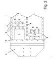
- the versatility of the clamping system shows Fig. 2 ,
- two workpieces 7 of different sizes are clamped by forming two frames 9.
- the two frames 9 are formed by the stop element 1, by three arms 2 and by two clamping bracket 3.
- the flexibility is achieved by the multiplicity of connecting elements 4 in the stop element 1, the arms 2 and the clamping straps 3.
- the two workpieces 7 are held firmly by the guided in the threaded holes 6 of the clamping bracket 3 screws 8.
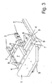
- the clamping system of Fig. 2 is in perspective Fig. 3 shown.
- a reference element 5 is attached to the underside of the stop element 1. This reference element 5 serves to use the clamping system in conjunction with a reference clamping system or a zero point clamping system.
Landscapes
- Engineering & Computer Science (AREA)
- Mechanical Engineering (AREA)
- Jigs For Machine Tools (AREA)
Abstract
Description
Die Erfindung betrifft ein Spannsystem zur Fixierung von Werkstücken.The invention relates to a clamping system for fixing workpieces.
Die Bearbeitung von metallischen Werkstücken ist häufig sehr komplex und kann eine Vielzahl von zerspanenden und spanlosen Arbeitsgängen an unterschiedlichen Bearbeitungsmaschinen umfassen, um das fertige Werkstück herzustellen. Insbesondere bei automatisierten Fertigungsabläufen ist es dabei wesentlich, dass das Werkstück bei jedem Arbeitsgang eine definierte Lage an dem jeweiligen Werkzeug annimmt.The machining of metallic workpieces is often very complex and can include a variety of machining and cutting operations on different machine tools to produce the finished workpiece. In particular, in automated production processes, it is essential that the workpiece assumes a defined position on the respective tool with each operation.
Vielfach werden die Werkstücke zwischen Backen auf einer Trägerplatte eingespannt, oder sie werden in vorbereitete Öffnungen eingeklebt, wobei dann aber lange Wartezeiten erforderlich sind, bis mit der eigentlichen Bearbeitung begonnen werden kann.In many cases, the workpieces are clamped between jaws on a support plate, or they are glued into prepared openings, but then long waiting times are required until the actual processing can be started.
Aus der
Die Aufgabe der vorliegenden Erfindung besteht insbesondere darin, ein Spannsystem mit möglichst kleinen Rüstzeiten vorzuschlagen, welches mit einfachen Handgriffen bedienbar ist und auch für unterschiedliche Werkstückgrössen geeignet ist.The object of the present invention is in particular to propose a clamping system with the shortest possible set-up times, which can be operated with simple steps and is also suitable for different workpiece sizes.
Erfindungsgemäss wird die Erfindung dadurch gelöst, dass es ein Anschlagelement , mindestens zwei Ausleger und mindestens einen Spannbügel aufweist, wobei im Anschlagelement, in den Auslegern und im Spannbügel Mittel zur formschlüssigen, schraubfreien Verbindung des Anschlagelementes mit den Auslegern einerseits und zum Verbinden der Ausleger mit dem Spannbügel andererseits zur Bildung eines stabilen Rahmens vorgesehen sind.According to the invention, the invention is achieved in that it has a stop element, at least two arms and at least one clamping bracket, wherein in the stop element, in the arms and in the clamping device means for positive, screw-free connection of the stop element with the Jibs on the one hand and for connecting the boom with the clamping bracket on the other hand are provided to form a stable frame.
Das Spannsystem zeichnet sich insbesondere dadurch aus, dass ein Spannrahmen aus verschiedenen teilen ohne Schrauben kraftschlüssig zusammensteckbar ist und einerseits mehr als ein Werkstück und andererseits Werkstücke verschiedener Grösse einspannbar sind.The clamping system is characterized in particular by the fact that a clamping frame of different parts without screws is frictionally plugged together and on the one hand more than a workpiece and on the other hand workpieces of different sizes are clamped.
Durch dieses Spannsystem werden insbesondere die Rüstzeiten bis nahezu 60% gegenüber dem Stand der Technik reduziert. Die Handhabung ist sehr einfach. Daher kann die Arbeitsvorbereitung in optimaler Weise erfolgen. Ferner zeichnet sich das Spannsystem durch eine geringe Anzahl von Einzelelementen aus.By this clamping system in particular the set-up times are reduced to nearly 60% compared to the prior art. The handling is very simple. Therefore, the work preparation can be done in an optimal way. Furthermore, the clamping system is characterized by a small number of individual elements.
In vorteilhafter Weise ist das Spannsystem mit einem Referenzelement zur Verbindung mit einem Referenzspannsystem oder Nullpunktspannsystem ausgerüstet, wobei das Referenzelement beispielsweise als Palette, als ein Zapfen oder ähnliches ausgebildet ist.Advantageously, the clamping system is equipped with a reference element for connection to a reference clamping system or zero point clamping system, wherein the reference element is formed for example as a pallet, as a pin or the like.
Die Verbindungsmittel der einzelnen miteinander zu verbindenden Teile sind bevorzugt konische Steckverbindungen verschiedener Ausbildungsformen und Grössen.The connecting means of the individual parts to be joined together are preferably conical connectors of various forms and sizes.
Das Spannsystem, insbesondre der Spannrahmen ist form-, kraftschlüssig und schraubenfrei ausgebildet. Lediglich das eigentliche Werkstück wird mittels Schrauben oder Gewindestifte an das Anschlagelement eingespannt. Um dem Spannrahmen zusätzliche Formstabilität und Verschleissfestigkeit zu geben, können alle Komponenten gehärtet sein. Ein weiterer Vorteil des Spannsystems besteht darin, dass die Bearbeitung vibrationsfrei erfolgen kann. Das Spannsystem zeichnet sich durch hohe Flexibilität in der Konfiguration der Werkstückaufnahmen aus.The clamping system, in particular the clamping frame is formed form-fit, non-positive and screw-free. Only the actual workpiece is clamped by means of screws or set screws to the stop element. To give the tenter additional dimensional stability and wear resistance, all components can be hardened. Another advantage of the clamping system is that the machining can be vibration-free. The clamping system is characterized by high flexibility in the configuration of the workpiece holders.
Die Erfindung wird an einem Beispiel eines Spannsystems näher erläutert. Es zeigen:
-
Fig. 1 ein Spannsystem mit einem eingespannten Werkstück -
Fig. 2 ein Spannsystem mit zwei Werkstücken verschiedener Grössen -
Fig. 3 eine dreidimensionale Ansicht eines Spannsystems.
-
Fig. 1 a clamping system with a clamped workpiece -
Fig. 2 a clamping system with two workpieces of different sizes -
Fig. 3 a three-dimensional view of a clamping system.
In
Die Vielseitigkeit des Spannsystems zeigt
Das Spannsystem der
- 11
- Anschlagelementstop element
- 22
- Auslegerboom
- 33
- Spannbügeltensioning bow
- 44
- Verbindungsmittelconnecting means
- 55
- Referenzelementreference element
- 66
- Gewindelöcherthreaded holes
- 77
- Werkstückworkpiece
- 88th
- Schraubenscrew
- 99
- Rahmenframe
Claims (6)
Priority Applications (1)
| Application Number | Priority Date | Filing Date | Title |
|---|---|---|---|
| EP09169197A EP2292381A1 (en) | 2009-09-02 | 2009-09-02 | Tensioning system for workpieces |
Applications Claiming Priority (1)
| Application Number | Priority Date | Filing Date | Title |
|---|---|---|---|
| EP09169197A EP2292381A1 (en) | 2009-09-02 | 2009-09-02 | Tensioning system for workpieces |
Publications (1)
| Publication Number | Publication Date |
|---|---|
| EP2292381A1 true EP2292381A1 (en) | 2011-03-09 |
Family
ID=41567197
Family Applications (1)
| Application Number | Title | Priority Date | Filing Date |
|---|---|---|---|
| EP09169197A Withdrawn EP2292381A1 (en) | 2009-09-02 | 2009-09-02 | Tensioning system for workpieces |
Country Status (1)
| Country | Link |
|---|---|
| EP (1) | EP2292381A1 (en) |
Cited By (2)
| Publication number | Priority date | Publication date | Assignee | Title |
|---|---|---|---|---|
| EP2961504A4 (en) * | 2013-03-01 | 2016-12-07 | Steven E Phillips | Modular fixture plate system for positioning a workpiece during a manufacturing and/or inspection process |
| US11969847B2 (en) | 2021-05-19 | 2024-04-30 | Metrologyworks, Inc. | Modular fixture plate alignment system |
Citations (6)
| Publication number | Priority date | Publication date | Assignee | Title |
|---|---|---|---|---|
| DE178700C (en) * | ||||
| DE611344C (en) * | 1935-03-26 | Richard Wirsbitzke | Screw clamp | |
| GB1048935A (en) * | 1962-05-10 | 1966-11-23 | Bernard Charles Roach | Work holding clamp |
| DE1237292B (en) * | 1958-03-12 | 1967-03-23 | Hulda Erna Mayer Geb Moosmann | Stenter frame |
| US4132396A (en) * | 1978-04-06 | 1979-01-02 | Graham George W | Glueing clamp assembly |
| DE20313551U1 (en) | 2003-08-29 | 2005-01-05 | Kuka Schweissanlagen Gmbh | Kit for forming a spatial linkage for the positioning of work elements |
-
2009
- 2009-09-02 EP EP09169197A patent/EP2292381A1/en not_active Withdrawn
Patent Citations (6)
| Publication number | Priority date | Publication date | Assignee | Title |
|---|---|---|---|---|
| DE178700C (en) * | ||||
| DE611344C (en) * | 1935-03-26 | Richard Wirsbitzke | Screw clamp | |
| DE1237292B (en) * | 1958-03-12 | 1967-03-23 | Hulda Erna Mayer Geb Moosmann | Stenter frame |
| GB1048935A (en) * | 1962-05-10 | 1966-11-23 | Bernard Charles Roach | Work holding clamp |
| US4132396A (en) * | 1978-04-06 | 1979-01-02 | Graham George W | Glueing clamp assembly |
| DE20313551U1 (en) | 2003-08-29 | 2005-01-05 | Kuka Schweissanlagen Gmbh | Kit for forming a spatial linkage for the positioning of work elements |
Cited By (6)
| Publication number | Priority date | Publication date | Assignee | Title |
|---|---|---|---|---|
| EP2961504A4 (en) * | 2013-03-01 | 2016-12-07 | Steven E Phillips | Modular fixture plate system for positioning a workpiece during a manufacturing and/or inspection process |
| EP2961504B1 (en) | 2013-03-01 | 2018-11-28 | Steven E. Phillips | Modular fixture plate system for positioning a workpiece during a manufacturing and/or inspection process |
| US10183380B2 (en) | 2013-03-01 | 2019-01-22 | Steven E. Phillips | Modular fixture plate system for positioning a workpiece during a manufacturing and/or inspection process |
| US11458597B2 (en) | 2013-03-01 | 2022-10-04 | Steven E. Phillips | Modular fixture plate system for positioning a workpiece during a manufacturing and/or inspection process |
| US12097594B2 (en) | 2013-03-01 | 2024-09-24 | Steven E. Phillips | Modular fixture plate system for positioning a workpiece during a manufacturing and/or inspection process |
| US11969847B2 (en) | 2021-05-19 | 2024-04-30 | Metrologyworks, Inc. | Modular fixture plate alignment system |
Similar Documents
| Publication | Publication Date | Title |
|---|---|---|
| WO2014015967A1 (en) | Cam drive | |
| EP3769905A1 (en) | Device for positioning motor vehicle parts | |
| DE2822516C3 (en) | Cut-off machine | |
| AT523568A1 (en) | Bending machine | |
| EP3326748A1 (en) | Method for machining | |
| DE202006011245U1 (en) | Clamping system e.g. for tool machines, has two or four facing, prism shaped clamping parts arranged in narrow clamping area over entire workpiece length | |
| EP2292381A1 (en) | Tensioning system for workpieces | |
| EP1752253A1 (en) | Clamping device and method for machining a workpiece clamped on such a clamping device | |
| DE102016102940B4 (en) | Method and processing device for processing, in particular for reshaping elongated material sections, and clamping unit for carrying out the method | |
| DE29813637U1 (en) | Vector holding device suitable for automatic centering | |
| EP1402985A3 (en) | Clamping device | |
| DE102013001759B3 (en) | Multifunctional clamping device for use in horizontal processing machine for clamping metals, has clamping wings pivoted around pivot point by changing angle between individual clamping surfaces, which are formed by wing surfaces | |
| DE2405954A1 (en) | DEVICE FOR TURNING PRISMATIC OR APPROXIMATELY PRISMATIC BODIES SUCH AS ROLLING BLOCKS OR BARS | |
| DE10391648B4 (en) | Support device for Spanngut in a jig | |
| DE10120009A1 (en) | Tool holding device has third casing able to be clamped between first and second holders | |
| EP2998065B1 (en) | Processing device with a workpiece table | |
| DE138588C (en) | ||
| DE647329C (en) | Jig for woodworking | |
| DD228199A1 (en) | DEVICE FOR TIGHTENING DIFFERENT WORKPIECES | |
| DE20311975U1 (en) | Pliers have handles thickening from pivot zone to handle tips and incorporating permanent magnets | |
| DE3824997C1 (en) | ||
| DE3616451A1 (en) | DEVICE FOR SETTING FASTENING ELEMENTS | |
| DE202004009601U1 (en) | Work piece clamping sheet, attached to base on turntable with two parallel joints and connecting element | |
| DE3828791C2 (en) | Device for dressing circuit boards | |
| DE10045931A1 (en) | Clamping system has frame parts containing edge-grooves clamping elements, counter-holders, screws or tenon blocks. |
Legal Events
| Date | Code | Title | Description |
|---|---|---|---|
| PUAI | Public reference made under article 153(3) epc to a published international application that has entered the european phase |
Free format text: ORIGINAL CODE: 0009012 |
|
| AK | Designated contracting states |
Kind code of ref document: A1 Designated state(s): AT BE BG CH CY CZ DE DK EE ES FI FR GB GR HR HU IE IS IT LI LT LU LV MC MK MT NL NO PL PT RO SE SI SK SM TR |
|
| AX | Request for extension of the european patent |
Extension state: AL BA RS |
|
| STAA | Information on the status of an ep patent application or granted ep patent |
Free format text: STATUS: THE APPLICATION IS DEEMED TO BE WITHDRAWN |
|
| 18D | Application deemed to be withdrawn |
Effective date: 20110910 |