EP2292381A1 - Système de tension pour pièces usinées - Google Patents
Système de tension pour pièces usinées Download PDFInfo
- Publication number
- EP2292381A1 EP2292381A1 EP09169197A EP09169197A EP2292381A1 EP 2292381 A1 EP2292381 A1 EP 2292381A1 EP 09169197 A EP09169197 A EP 09169197A EP 09169197 A EP09169197 A EP 09169197A EP 2292381 A1 EP2292381 A1 EP 2292381A1
- Authority
- EP
- European Patent Office
- Prior art keywords
- clamping
- clamping system
- arms
- stop element
- workpieces
- Prior art date
- Legal status (The legal status is an assumption and is not a legal conclusion. Google has not performed a legal analysis and makes no representation as to the accuracy of the status listed.)
- Withdrawn
Links
Images

Classifications
-
- B—PERFORMING OPERATIONS; TRANSPORTING
- B25—HAND TOOLS; PORTABLE POWER-DRIVEN TOOLS; MANIPULATORS
- B25B—TOOLS OR BENCH DEVICES NOT OTHERWISE PROVIDED FOR, FOR FASTENING, CONNECTING, DISENGAGING OR HOLDING
- B25B5/00—Clamps
- B25B5/003—Combinations of clamps
-
- B—PERFORMING OPERATIONS; TRANSPORTING
- B25—HAND TOOLS; PORTABLE POWER-DRIVEN TOOLS; MANIPULATORS
- B25B—TOOLS OR BENCH DEVICES NOT OTHERWISE PROVIDED FOR, FOR FASTENING, CONNECTING, DISENGAGING OR HOLDING
- B25B11/00—Work holders not covered by any preceding group in the subclass, e.g. magnetic work holders, vacuum work holders
Definitions
- the invention relates to a clamping system for fixing workpieces.
- machining of metallic workpieces is often very complex and can include a variety of machining and cutting operations on different machine tools to produce the finished workpiece.
- the workpieces are clamped between jaws on a support plate, or they are glued into prepared openings, but then long waiting times are required until the actual processing can be started.
- the object of the present invention is in particular to propose a clamping system with the shortest possible set-up times, which can be operated with simple steps and is also suitable for different workpiece sizes.
- the invention is achieved in that it has a stop element, at least two arms and at least one clamping bracket, wherein in the stop element, in the arms and in the clamping device means for positive, screw-free connection of the stop element with the Jibs on the one hand and for connecting the boom with the clamping bracket on the other hand are provided to form a stable frame.
- the clamping system is characterized in particular by the fact that a clamping frame of different parts without screws is frictionally plugged together and on the one hand more than a workpiece and on the other hand workpieces of different sizes are clamped.
- the clamping system in particular the set-up times are reduced to nearly 60% compared to the prior art.
- the handling is very simple. Therefore, the work preparation can be done in an optimal way.
- the clamping system is characterized by a small number of individual elements.
- the clamping system is equipped with a reference element for connection to a reference clamping system or zero point clamping system, wherein the reference element is formed for example as a pallet, as a pin or the like.
- the connecting means of the individual parts to be joined together are preferably conical connectors of various forms and sizes.
- the clamping system in particular the clamping frame is formed form-fit, non-positive and screw-free. Only the actual workpiece is clamped by means of screws or set screws to the stop element. To give the tenter additional dimensional stability and wear resistance, all components can be hardened. Another advantage of the clamping system is that the machining can be vibration-free.
- the clamping system is characterized by high flexibility in the configuration of the workpiece holders.
- a clamping system is shown with a clamped workpiece 7, the clamping system consists essentially of a frame 9, which is formed from a stop element 1, two arms 2 and a clamping bracket 3.
- the stop element 1, the two arms 2 and the clamping bracket 3 have connecting means 4, which are designed as plug-in connections.
- the connecting means 4 are conical, which ensures a stable frame.
- threaded holes 6 are provided for screws 8 for clamping the workpiece 7.
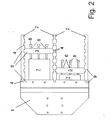
- the versatility of the clamping system shows Fig. 2 ,
- two workpieces 7 of different sizes are clamped by forming two frames 9.
- the two frames 9 are formed by the stop element 1, by three arms 2 and by two clamping bracket 3.
- the flexibility is achieved by the multiplicity of connecting elements 4 in the stop element 1, the arms 2 and the clamping straps 3.
- the two workpieces 7 are held firmly by the guided in the threaded holes 6 of the clamping bracket 3 screws 8.
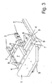
- the clamping system of Fig. 2 is in perspective Fig. 3 shown.
- a reference element 5 is attached to the underside of the stop element 1. This reference element 5 serves to use the clamping system in conjunction with a reference clamping system or a zero point clamping system.
Landscapes
- Engineering & Computer Science (AREA)
- Mechanical Engineering (AREA)
- Jigs For Machine Tools (AREA)
Priority Applications (1)
| Application Number | Priority Date | Filing Date | Title |
|---|---|---|---|
| EP09169197A EP2292381A1 (fr) | 2009-09-02 | 2009-09-02 | Système de tension pour pièces usinées |
Applications Claiming Priority (1)
| Application Number | Priority Date | Filing Date | Title |
|---|---|---|---|
| EP09169197A EP2292381A1 (fr) | 2009-09-02 | 2009-09-02 | Système de tension pour pièces usinées |
Publications (1)
| Publication Number | Publication Date |
|---|---|
| EP2292381A1 true EP2292381A1 (fr) | 2011-03-09 |
Family
ID=41567197
Family Applications (1)
| Application Number | Title | Priority Date | Filing Date |
|---|---|---|---|
| EP09169197A Withdrawn EP2292381A1 (fr) | 2009-09-02 | 2009-09-02 | Système de tension pour pièces usinées |
Country Status (1)
| Country | Link |
|---|---|
| EP (1) | EP2292381A1 (fr) |
Cited By (2)
| Publication number | Priority date | Publication date | Assignee | Title |
|---|---|---|---|---|
| EP2961504A4 (fr) * | 2013-03-01 | 2016-12-07 | Steven E Phillips | Système de plaque de fixation modulaire pour le positionnement d'une pièce lors d'un procédé de fabrication et/ou d'inspection |
| US11969847B2 (en) | 2021-05-19 | 2024-04-30 | Metrologyworks, Inc. | Modular fixture plate alignment system |
Citations (6)
| Publication number | Priority date | Publication date | Assignee | Title |
|---|---|---|---|---|
| DE178700C (fr) * | ||||
| DE611344C (de) * | 1935-03-26 | Richard Wirsbitzke | Schraubzwinge | |
| GB1048935A (en) * | 1962-05-10 | 1966-11-23 | Bernard Charles Roach | Work holding clamp |
| DE1237292B (de) * | 1958-03-12 | 1967-03-23 | Hulda Erna Mayer Geb Moosmann | Spannrahmen |
| US4132396A (en) * | 1978-04-06 | 1979-01-02 | Graham George W | Glueing clamp assembly |
| DE20313551U1 (de) | 2003-08-29 | 2005-01-05 | Kuka Schweissanlagen Gmbh | Bausatz zur Bildung eines räumlichen Gestänges für das Positionieren von Arbeitselementen |
-
2009
- 2009-09-02 EP EP09169197A patent/EP2292381A1/fr not_active Withdrawn
Patent Citations (6)
| Publication number | Priority date | Publication date | Assignee | Title |
|---|---|---|---|---|
| DE178700C (fr) * | ||||
| DE611344C (de) * | 1935-03-26 | Richard Wirsbitzke | Schraubzwinge | |
| DE1237292B (de) * | 1958-03-12 | 1967-03-23 | Hulda Erna Mayer Geb Moosmann | Spannrahmen |
| GB1048935A (en) * | 1962-05-10 | 1966-11-23 | Bernard Charles Roach | Work holding clamp |
| US4132396A (en) * | 1978-04-06 | 1979-01-02 | Graham George W | Glueing clamp assembly |
| DE20313551U1 (de) | 2003-08-29 | 2005-01-05 | Kuka Schweissanlagen Gmbh | Bausatz zur Bildung eines räumlichen Gestänges für das Positionieren von Arbeitselementen |
Cited By (6)
| Publication number | Priority date | Publication date | Assignee | Title |
|---|---|---|---|---|
| EP2961504A4 (fr) * | 2013-03-01 | 2016-12-07 | Steven E Phillips | Système de plaque de fixation modulaire pour le positionnement d'une pièce lors d'un procédé de fabrication et/ou d'inspection |
| EP2961504B1 (fr) | 2013-03-01 | 2018-11-28 | Steven E. Phillips | Système de plaque de fixation modulaire pour le positionnement d'une pièce lors d'un procédé de fabrication et/ou d'inspection |
| US10183380B2 (en) | 2013-03-01 | 2019-01-22 | Steven E. Phillips | Modular fixture plate system for positioning a workpiece during a manufacturing and/or inspection process |
| US11458597B2 (en) | 2013-03-01 | 2022-10-04 | Steven E. Phillips | Modular fixture plate system for positioning a workpiece during a manufacturing and/or inspection process |
| US12097594B2 (en) | 2013-03-01 | 2024-09-24 | Steven E. Phillips | Modular fixture plate system for positioning a workpiece during a manufacturing and/or inspection process |
| US11969847B2 (en) | 2021-05-19 | 2024-04-30 | Metrologyworks, Inc. | Modular fixture plate alignment system |
Similar Documents
| Publication | Publication Date | Title |
|---|---|---|
| WO2014015967A1 (fr) | Mécanisme à coin | |
| DE2822516C3 (de) | Trennschleifmaschine | |
| AT523568A1 (de) | Biegemaschine | |
| EP3326748A1 (fr) | Procédé d'usinage par enlèvement de copeaux d'aubes de turbine | |
| DE202006011245U1 (de) | Spannsystem für Werkzeugmaschinen | |
| EP2292381A1 (fr) | Système de tension pour pièces usinées | |
| EP1752253A1 (fr) | Dispositif de serrage et procédé pour usiner des pièces à travailler serrées sur un tel dispositif de serrage | |
| DE102016102940B4 (de) | Verfahren und Bearbeitungseinrichtung zum Bearbeiten, insbesondere zum Umformen von länglichen Materialabschnitten, und Spanneinheit zur Durchführung des Verfahrens | |
| DE29813637U1 (de) | Vektorhaltevorrichtung mit Eignung zum automatischen Zentrieren | |
| CH665158A5 (de) | Wechselpalette zum einspannen und ausrichten von werkstuecken. | |
| EP1402985A3 (fr) | Dispositif de serrage | |
| DE102013001759B3 (de) | Spannvorrichtung zum Spannen von Werkstücken mit einem Mittelteil in Form eines Spannturms | |
| DE102017001703B4 (de) | Vorrichtung zur Bearbeitung von Plattenkanten und Verfahren zum Besäumen einer Platte | |
| DE2405954A1 (de) | Einrichtung zum umwenden prismatischer oder annaehernd prismatischer koerper wie walzeisenbloecke oder barren | |
| DE10120009A1 (de) | Werkstückhaltevorrichtung und Werkstückhalteverfahren für eine Werkzeugmaschine | |
| EP2998065B1 (fr) | Dispositif de traitement dote d'une table porte-piece | |
| DE138588C (fr) | ||
| DE647329C (de) | Spannvorrichtung fuer die Holzbearbeitung | |
| DD228199A1 (de) | Vorrichtung zum spannen verschiedenartiger werkstuecke | |
| DE20311975U1 (de) | Griffaufbau für ein Klemmwerkzeug | |
| DE3824997C1 (fr) | ||
| DE3616451A1 (de) | Vorrichtung zum setzen von befestigungselementen | |
| DE202004009601U1 (de) | Vorrichtung zur Aufnahme von ein oder mehreren Werkzeugplatten | |
| DE3828791C2 (de) | Vorrichtung zum Zurichten von Schaltkarten | |
| DE10045931A1 (de) | Spannsystem |
Legal Events
| Date | Code | Title | Description |
|---|---|---|---|
| PUAI | Public reference made under article 153(3) epc to a published international application that has entered the european phase |
Free format text: ORIGINAL CODE: 0009012 |
|
| AK | Designated contracting states |
Kind code of ref document: A1 Designated state(s): AT BE BG CH CY CZ DE DK EE ES FI FR GB GR HR HU IE IS IT LI LT LU LV MC MK MT NL NO PL PT RO SE SI SK SM TR |
|
| AX | Request for extension of the european patent |
Extension state: AL BA RS |
|
| STAA | Information on the status of an ep patent application or granted ep patent |
Free format text: STATUS: THE APPLICATION IS DEEMED TO BE WITHDRAWN |
|
| 18D | Application deemed to be withdrawn |
Effective date: 20110910 |