EP2961350B1 - Nasenimplantate und systeme - Google Patents
Nasenimplantate und systeme Download PDFInfo
- Publication number
- EP2961350B1 EP2961350B1 EP14756699.6A EP14756699A EP2961350B1 EP 2961350 B1 EP2961350 B1 EP 2961350B1 EP 14756699 A EP14756699 A EP 14756699A EP 2961350 B1 EP2961350 B1 EP 2961350B1
- Authority
- EP
- European Patent Office
- Prior art keywords
- implant
- needle
- nasal
- tissue
- conduit
- Prior art date
- Legal status (The legal status is an assumption and is not a legal conclusion. Google has not performed a legal analysis and makes no representation as to the accuracy of the status listed.)
- Active
Links
- 239000007943 implant Substances 0.000 title claims description 900
- 239000000463 material Substances 0.000 claims description 30
- 229920001432 poly(L-lactide) Polymers 0.000 claims description 7
- JVTAAEKCZFNVCJ-REOHCLBHSA-N L-lactic acid Chemical compound C[C@H](O)C(O)=O JVTAAEKCZFNVCJ-REOHCLBHSA-N 0.000 claims description 5
- 230000000994 depressogenic effect Effects 0.000 claims description 3
- JVTAAEKCZFNVCJ-UWTATZPHSA-N D-lactic acid Chemical compound C[C@@H](O)C(O)=O JVTAAEKCZFNVCJ-UWTATZPHSA-N 0.000 claims description 2
- 229940022769 d- lactic acid Drugs 0.000 claims description 2
- 210000001519 tissue Anatomy 0.000 description 275
- 210000000845 cartilage Anatomy 0.000 description 43
- 238000000034 method Methods 0.000 description 40
- 210000001331 nose Anatomy 0.000 description 40
- 238000010438 heat treatment Methods 0.000 description 39
- 238000007493 shaping process Methods 0.000 description 35
- 230000033001 locomotion Effects 0.000 description 31
- 238000005520 cutting process Methods 0.000 description 26
- 238000003780 insertion Methods 0.000 description 25
- 230000037431 insertion Effects 0.000 description 25
- 230000007246 mechanism Effects 0.000 description 23
- 238000000429 assembly Methods 0.000 description 16
- 230000000712 assembly Effects 0.000 description 16
- 210000000988 bone and bone Anatomy 0.000 description 13
- 210000002050 maxilla Anatomy 0.000 description 13
- 238000012360 testing method Methods 0.000 description 13
- 230000006870 function Effects 0.000 description 11
- 238000002513 implantation Methods 0.000 description 11
- 238000013508 migration Methods 0.000 description 10
- 238000001356 surgical procedure Methods 0.000 description 9
- 210000003484 anatomy Anatomy 0.000 description 8
- 230000005012 migration Effects 0.000 description 7
- 210000004877 mucosa Anatomy 0.000 description 7
- 230000036407 pain Effects 0.000 description 7
- 238000011084 recovery Methods 0.000 description 7
- 238000013459 approach Methods 0.000 description 6
- 230000008901 benefit Effects 0.000 description 6
- 230000007774 longterm Effects 0.000 description 6
- 230000008439 repair process Effects 0.000 description 6
- 238000011282 treatment Methods 0.000 description 6
- 210000001944 turbinate Anatomy 0.000 description 6
- 238000005452 bending Methods 0.000 description 5
- 230000004044 response Effects 0.000 description 5
- 210000003491 skin Anatomy 0.000 description 5
- 208000024891 symptom Diseases 0.000 description 5
- 230000000451 tissue damage Effects 0.000 description 5
- 231100000827 tissue damage Toxicity 0.000 description 5
- 206010028748 Nasal obstruction Diseases 0.000 description 4
- 230000008859 change Effects 0.000 description 4
- 230000000694 effects Effects 0.000 description 4
- 210000003811 finger Anatomy 0.000 description 4
- 238000002347 injection Methods 0.000 description 4
- 239000007924 injection Substances 0.000 description 4
- 210000004072 lung Anatomy 0.000 description 4
- 238000002324 minimally invasive surgery Methods 0.000 description 4
- 235000020637 scallop Nutrition 0.000 description 4
- 210000004872 soft tissue Anatomy 0.000 description 4
- 239000000243 solution Substances 0.000 description 4
- NOQGZXFMHARMLW-UHFFFAOYSA-N Daminozide Chemical compound CN(C)NC(=O)CCC(O)=O NOQGZXFMHARMLW-UHFFFAOYSA-N 0.000 description 3
- 241000237503 Pectinidae Species 0.000 description 3
- 230000009471 action Effects 0.000 description 3
- 239000002537 cosmetic Substances 0.000 description 3
- 230000009477 glass transition Effects 0.000 description 3
- 238000001727 in vivo Methods 0.000 description 3
- 238000002360 preparation method Methods 0.000 description 3
- 230000029058 respiratory gaseous exchange Effects 0.000 description 3
- 238000010008 shearing Methods 0.000 description 3
- 238000003860 storage Methods 0.000 description 3
- 230000001225 therapeutic effect Effects 0.000 description 3
- 206010002091 Anaesthesia Diseases 0.000 description 2
- -1 PDLA Polymers 0.000 description 2
- 229920005689 PLLA-PGA Polymers 0.000 description 2
- 206010041235 Snoring Diseases 0.000 description 2
- 230000001154 acute effect Effects 0.000 description 2
- 230000032683 aging Effects 0.000 description 2
- 230000037005 anaesthesia Effects 0.000 description 2
- QVGXLLKOCUKJST-UHFFFAOYSA-N atomic oxygen Chemical compound [O] QVGXLLKOCUKJST-UHFFFAOYSA-N 0.000 description 2
- 229920001577 copolymer Polymers 0.000 description 2
- 230000002349 favourable effect Effects 0.000 description 2
- 230000003176 fibrotic effect Effects 0.000 description 2
- 208000014674 injury Diseases 0.000 description 2
- 238000009413 insulation Methods 0.000 description 2
- 230000009545 invasion Effects 0.000 description 2
- 239000003589 local anesthetic agent Substances 0.000 description 2
- 230000013011 mating Effects 0.000 description 2
- 210000003205 muscle Anatomy 0.000 description 2
- 210000000492 nasalseptum Anatomy 0.000 description 2
- 229910052760 oxygen Inorganic materials 0.000 description 2
- 239000001301 oxygen Substances 0.000 description 2
- 238000004806 packaging method and process Methods 0.000 description 2
- 229920001434 poly(D-lactide) Polymers 0.000 description 2
- 229920000747 poly(lactic acid) Polymers 0.000 description 2
- 229920000642 polymer Polymers 0.000 description 2
- 230000008569 process Effects 0.000 description 2
- 238000002271 resection Methods 0.000 description 2
- 238000002435 rhinoplasty Methods 0.000 description 2
- 201000002859 sleep apnea Diseases 0.000 description 2
- 230000035882 stress Effects 0.000 description 2
- 210000003813 thumb Anatomy 0.000 description 2
- 230000008733 trauma Effects 0.000 description 2
- 229930182843 D-Lactic acid Natural products 0.000 description 1
- 206010013975 Dyspnoeas Diseases 0.000 description 1
- 208000034530 PLAA-associated neurodevelopmental disease Diseases 0.000 description 1
- 241000237509 Patinopecten sp. Species 0.000 description 1
- 208000006735 Periostitis Diseases 0.000 description 1
- 230000003213 activating effect Effects 0.000 description 1
- 230000002411 adverse Effects 0.000 description 1
- 230000004075 alteration Effects 0.000 description 1
- 238000004873 anchoring Methods 0.000 description 1
- 230000002421 anti-septic effect Effects 0.000 description 1
- 230000009286 beneficial effect Effects 0.000 description 1
- 229920000249 biocompatible polymer Polymers 0.000 description 1
- 230000015572 biosynthetic process Effects 0.000 description 1
- 239000008280 blood Substances 0.000 description 1
- 210000004369 blood Anatomy 0.000 description 1
- 230000006652 catabolic pathway Effects 0.000 description 1
- 230000015556 catabolic process Effects 0.000 description 1
- 238000001816 cooling Methods 0.000 description 1
- 230000006378 damage Effects 0.000 description 1
- 238000006731 degradation reaction Methods 0.000 description 1
- 230000001419 dependent effect Effects 0.000 description 1
- 230000000881 depressing effect Effects 0.000 description 1
- 210000004207 dermis Anatomy 0.000 description 1
- 238000013461 design Methods 0.000 description 1
- 238000002224 dissection Methods 0.000 description 1
- 238000011156 evaluation Methods 0.000 description 1
- 238000001125 extrusion Methods 0.000 description 1
- 235000013305 food Nutrition 0.000 description 1
- 230000035876 healing Effects 0.000 description 1
- 230000036541 health Effects 0.000 description 1
- 238000003384 imaging method Methods 0.000 description 1
- 230000006872 improvement Effects 0.000 description 1
- 238000011065 in-situ storage Methods 0.000 description 1
- 239000012774 insulation material Substances 0.000 description 1
- 230000003993 interaction Effects 0.000 description 1
- 230000002045 lasting effect Effects 0.000 description 1
- 238000004519 manufacturing process Methods 0.000 description 1
- 210000000537 nasal bone Anatomy 0.000 description 1
- 210000002184 nasal cartilage Anatomy 0.000 description 1
- 210000002850 nasal mucosa Anatomy 0.000 description 1
- 230000000149 penetrating effect Effects 0.000 description 1
- 230000035515 penetration Effects 0.000 description 1
- 210000003460 periosteum Anatomy 0.000 description 1
- 229920003023 plastic Polymers 0.000 description 1
- 238000003825 pressing Methods 0.000 description 1
- 230000009467 reduction Effects 0.000 description 1
- 239000012858 resilient material Substances 0.000 description 1
- 239000011343 solid material Substances 0.000 description 1
- 230000001954 sterilising effect Effects 0.000 description 1
- 238000004659 sterilization and disinfection Methods 0.000 description 1
- 238000011477 surgical intervention Methods 0.000 description 1
- 239000002470 thermal conductor Substances 0.000 description 1
- 230000007704 transition Effects 0.000 description 1
- 230000000007 visual effect Effects 0.000 description 1
- 239000011800 void material Substances 0.000 description 1
- 238000010792 warming Methods 0.000 description 1
- XLYOFNOQVPJJNP-UHFFFAOYSA-N water Substances O XLYOFNOQVPJJNP-UHFFFAOYSA-N 0.000 description 1
- 230000003245 working effect Effects 0.000 description 1
Images


Classifications
-
- A—HUMAN NECESSITIES
- A61—MEDICAL OR VETERINARY SCIENCE; HYGIENE
- A61F—FILTERS IMPLANTABLE INTO BLOOD VESSELS; PROSTHESES; DEVICES PROVIDING PATENCY TO, OR PREVENTING COLLAPSING OF, TUBULAR STRUCTURES OF THE BODY, e.g. STENTS; ORTHOPAEDIC, NURSING OR CONTRACEPTIVE DEVICES; FOMENTATION; TREATMENT OR PROTECTION OF EYES OR EARS; BANDAGES, DRESSINGS OR ABSORBENT PADS; FIRST-AID KITS
- A61F2/00—Filters implantable into blood vessels; Prostheses, i.e. artificial substitutes or replacements for parts of the body; Appliances for connecting them with the body; Devices providing patency to, or preventing collapsing of, tubular structures of the body, e.g. stents
- A61F2/02—Prostheses implantable into the body
- A61F2/18—Internal ear or nose parts, e.g. ear-drums
- A61F2/186—Nose parts
-
- A—HUMAN NECESSITIES
- A61—MEDICAL OR VETERINARY SCIENCE; HYGIENE
- A61B—DIAGNOSIS; SURGERY; IDENTIFICATION
- A61B17/00—Surgical instruments, devices or methods, e.g. tourniquets
- A61B17/34—Trocars; Puncturing needles
- A61B17/3468—Trocars; Puncturing needles for implanting or removing devices, e.g. prostheses, implants, seeds, wires
-
- A—HUMAN NECESSITIES
- A61—MEDICAL OR VETERINARY SCIENCE; HYGIENE
- A61F—FILTERS IMPLANTABLE INTO BLOOD VESSELS; PROSTHESES; DEVICES PROVIDING PATENCY TO, OR PREVENTING COLLAPSING OF, TUBULAR STRUCTURES OF THE BODY, e.g. STENTS; ORTHOPAEDIC, NURSING OR CONTRACEPTIVE DEVICES; FOMENTATION; TREATMENT OR PROTECTION OF EYES OR EARS; BANDAGES, DRESSINGS OR ABSORBENT PADS; FIRST-AID KITS
- A61F5/00—Orthopaedic methods or devices for non-surgical treatment of bones or joints; Nursing devices; Anti-rape devices
- A61F5/01—Orthopaedic devices, e.g. splints, casts or braces
- A61F5/08—Devices for correcting deformities of the nose ; Devices for enlarging the nostril, e.g. for breathing improvement
-
- A—HUMAN NECESSITIES
- A61—MEDICAL OR VETERINARY SCIENCE; HYGIENE
- A61L—METHODS OR APPARATUS FOR STERILISING MATERIALS OR OBJECTS IN GENERAL; DISINFECTION, STERILISATION OR DEODORISATION OF AIR; CHEMICAL ASPECTS OF BANDAGES, DRESSINGS, ABSORBENT PADS OR SURGICAL ARTICLES; MATERIALS FOR BANDAGES, DRESSINGS, ABSORBENT PADS OR SURGICAL ARTICLES
- A61L27/00—Materials for grafts or prostheses or for coating grafts or prostheses
- A61L27/14—Macromolecular materials
- A61L27/18—Macromolecular materials obtained otherwise than by reactions only involving carbon-to-carbon unsaturated bonds
-
- A—HUMAN NECESSITIES
- A61—MEDICAL OR VETERINARY SCIENCE; HYGIENE
- A61L—METHODS OR APPARATUS FOR STERILISING MATERIALS OR OBJECTS IN GENERAL; DISINFECTION, STERILISATION OR DEODORISATION OF AIR; CHEMICAL ASPECTS OF BANDAGES, DRESSINGS, ABSORBENT PADS OR SURGICAL ARTICLES; MATERIALS FOR BANDAGES, DRESSINGS, ABSORBENT PADS OR SURGICAL ARTICLES
- A61L27/00—Materials for grafts or prostheses or for coating grafts or prostheses
- A61L27/50—Materials characterised by their function or physical properties, e.g. injectable or lubricating compositions, shape-memory materials, surface modified materials
- A61L27/58—Materials at least partially resorbable by the body
-
- A—HUMAN NECESSITIES
- A61—MEDICAL OR VETERINARY SCIENCE; HYGIENE
- A61B—DIAGNOSIS; SURGERY; IDENTIFICATION
- A61B17/00—Surgical instruments, devices or methods, e.g. tourniquets
- A61B17/24—Surgical instruments, devices or methods, e.g. tourniquets for use in the oral cavity, larynx, bronchial passages or nose; Tongue scrapers
-
- A—HUMAN NECESSITIES
- A61—MEDICAL OR VETERINARY SCIENCE; HYGIENE
- A61F—FILTERS IMPLANTABLE INTO BLOOD VESSELS; PROSTHESES; DEVICES PROVIDING PATENCY TO, OR PREVENTING COLLAPSING OF, TUBULAR STRUCTURES OF THE BODY, e.g. STENTS; ORTHOPAEDIC, NURSING OR CONTRACEPTIVE DEVICES; FOMENTATION; TREATMENT OR PROTECTION OF EYES OR EARS; BANDAGES, DRESSINGS OR ABSORBENT PADS; FIRST-AID KITS
- A61F2/00—Filters implantable into blood vessels; Prostheses, i.e. artificial substitutes or replacements for parts of the body; Appliances for connecting them with the body; Devices providing patency to, or preventing collapsing of, tubular structures of the body, e.g. stents
- A61F2/02—Prostheses implantable into the body
- A61F2/18—Internal ear or nose parts, e.g. ear-drums
-
- A—HUMAN NECESSITIES
- A61—MEDICAL OR VETERINARY SCIENCE; HYGIENE
- A61F—FILTERS IMPLANTABLE INTO BLOOD VESSELS; PROSTHESES; DEVICES PROVIDING PATENCY TO, OR PREVENTING COLLAPSING OF, TUBULAR STRUCTURES OF THE BODY, e.g. STENTS; ORTHOPAEDIC, NURSING OR CONTRACEPTIVE DEVICES; FOMENTATION; TREATMENT OR PROTECTION OF EYES OR EARS; BANDAGES, DRESSINGS OR ABSORBENT PADS; FIRST-AID KITS
- A61F2230/00—Geometry of prostheses classified in groups A61F2/00 - A61F2/26 or A61F2/82 or A61F9/00 or A61F11/00 or subgroups thereof
- A61F2230/0002—Two-dimensional shapes, e.g. cross-sections
- A61F2230/0004—Rounded shapes, e.g. with rounded corners
- A61F2230/0008—Rounded shapes, e.g. with rounded corners elliptical or oval
-
- A—HUMAN NECESSITIES
- A61—MEDICAL OR VETERINARY SCIENCE; HYGIENE
- A61L—METHODS OR APPARATUS FOR STERILISING MATERIALS OR OBJECTS IN GENERAL; DISINFECTION, STERILISATION OR DEODORISATION OF AIR; CHEMICAL ASPECTS OF BANDAGES, DRESSINGS, ABSORBENT PADS OR SURGICAL ARTICLES; MATERIALS FOR BANDAGES, DRESSINGS, ABSORBENT PADS OR SURGICAL ARTICLES
- A61L2430/00—Materials or treatment for tissue regeneration
- A61L2430/34—Materials or treatment for tissue regeneration for soft tissue reconstruction
Definitions
- the present invention pertains to nasal implant delivery systems.
- the particular nasal anatomy of an individual may cause or contribute to various problems, such as cosmetic concerns, difficulty breathing, sleep apnea, or snoring, and impact an individual's health or reduce the quality of life.
- the structure of an external or internal nasal valve may resist airflow from the nose to the lungs and prevent an individual from getting sufficient oxygen to the blood.
- U.S. 8,133,276 , U.S. 7,780,730 , and U.S. 2012/0109298 describe implants that can be introduced into the nasal region of an individual using non-surgical injection techniques for treating a nasal valve of an individual.
- US 2008/077240 A1 discloses a method and system for treating internal nasal valve collapse.
- Treatment of the internal nasal valve includes injecting a working implant into the tissue of the patient, affecting the internal nasal valve of the patient.
- the injection of the implant of this invention into the tissue surrounding internal nasal valve causes an alteration or a change in the internal nasal valve angle.
- the implant may be cylindrical in shape and is of a size such that the implant can fit in the core of a needle (similar to a hypodermic needle). It is introduced into the nasal tissue by inserting the needle into the desired location. The implant is then maintained in that position by application of gentle pressure on the implant by an advancement shaft as the needle is withdrawn.
- implants for placing in a body tools for delivering the implants, and systems and methods for using implants and tools for placing in a body and more particularly to nasal implants, tools for delivering nasal implants, and systems and methods for using such implants and tools.
- These may be useful in minimally invasive procedures, including outpatient procedures, and may result in minimal pain and rapid recovery.
- These systems, assemblies and methods may be used, for example, in a doctor's office or clinic, and in some cases may require only a suitable local anesthetic.
- These implants, assemblies, systems, and methods may be especially useful for supporting or repairing nasal tissue, such as an internal nasal valve or an external nasal valve.
- a semi-permanent implant that degrades over a long time period may provide short-term nasal tissue support while the implant is intact and may initiate a body response (e.g. a fibrotic response) that strengthens nasal tissues and provides long-term nasal tissue support.
- a nasal treatment system may employ a pre-shaped or shapeable nasal implant including a bioresorbable material that provides structural support of surrounding nasal tissue. The assemblies and systems may penetrate through a patient's nasal tissue and allow precise positioning of an implant within a patient's nose.
- Various regions of airway tissue can impact airflow to the lungs.
- One major impact on airflow is from airflow resistance from the nose.
- the highest resistance structures in the nose may be the narrowest regions, such as the external nasal valve and the internal nasal valve.
- nasal valve cartilage around these valves prevents or reduces valve collapse and helps maintains airway patency.
- Incompetent internal and/or external valves can collapse and obstruct airflow during inhalation.
- problems with the nasal septum, nasal turbinates, lateral cartilage, or other structures due to, for example, aging, poorly formed or weak cartilage, surgery (e.g. rhinoplasty, septoplasty) and/or trauma can lead to nasal valve problems and impact airflow.
- Surgical treatments e.g. submucosal resection of turbinates, septoplasty
- These surgical treatments are invasive, uncomfortable and require significant time to recuperate.
- They do not readily address problems with the lateral cartilage wall.
- the lateral cartilage wall has been repaired, for example, by cartilaginous graft techniques using additional material (cartilage) from the nose or ear.
- these techniques are expensive (e.g. thousands of dollars), highly invasive, require a high level of surgical experience, have long, painful recovery times (e.g.
- Non-surgical approaches for nasal valve collapse include strips or stent-like materials (e.g. "BreathRight", Breathe with EEZ, Nozovent") that are placed on or around the nose. These temporary, suboptimal approaches suffer from limited efficacy and poor cosmesis.
- implants, assemblies, systems, and methods using implants, assemblies, and systems that may be used for supporting and repairing a body tissue. These may be useful in minimally invasive procedures, including outpatient procedures, and may result in minimal pain and rapid recovery. These systems, assemblies and methods may be used, for example, in a doctor's office or clinic, and in some cases may require only a suitable local anesthetic. These implants, assemblies, systems, and methods may be especially useful for supporting or repairing nasal tissue, such as an internal nasal valve or an external nasal valve.
- a semi-permanent implant that degrades over a long time period may provide short-term nasal tissue support while the implant is intact and may initiate a body response (e.g. a fibrotic response) that strengthens nasal tissues and provides long-term nasal tissue support.
- a nasal treatment system may employ a pre-shaped or shapeable nasal implant including a bioresorbable material that provides structural support of surrounding nasal tissue. The assemblies and systems may penetrate through a patient's nasal tissue and allow precise positioning of an implant within a patient's nose.
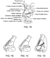
- FIG. 1A shows the underlying structural anatomy and tissues of a face with the muscles and skin removed. Bones of the nose and the rest of the face are indicated.
- An implant may be placed apposed to, within or attached or connected to any of the nasal tissues or surrounding tissues. In some embodiments, an implant is placed within a nasal tissue. In some embodiments, an implant is partially within a nasal tissue and partially within a surrounding tissue (e.g., a maxilla).
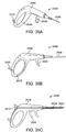
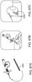
- FIGS. 1B and 1C show prior implants used for internal valve repair.
- FIG. 1B shows a spreader graft implanted into a patient's nose.
- FIG. 1C shows an alar batten graft implanted into a patient's nose.
- FIG. 1D shows four implants according to one embodiment of the invention implanted into a patient's nose to strengthen the nasal valves in these same regions. Any type of implant may be used, such as any of those described herein or in U.S. 8,133,276 , U.S. 7,780,730 , and U.S.
- a method for using an implant may include the steps of moving the implant though the mucosa, passing the implant through the nasal region medial to the lateral cartilage, and passing the implant along the maxilla.
- An implant may additionally, or instead, be placed for treating a spreader region, submucosally, between the lateral cartilage and septal cartilage.
- the implants are made of an absorbable material. They are implanted in positions that support the lateral wall cartilage and help resist or reduce movement of the cartilage during inhalation, thereby keeping the patient's airway open. As shown, the implants are positioned such that their distal most points are in close contact with the maxilla.
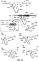
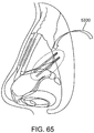
- FIG. 1F shows internal anatomy of a nose and a position (see oval in FIG. 1F ) in which an implant can be placed. Note that the implant crosses (or lies adjacent to) one region that is substantially maxillary bone and another region that is substantially cartilage.
- FIG. 1G shows an implant in place in nasal tissue, such as in the position shown in FIG. 1F relative to nasal bone 4830, the frontal process of the maxilla 4832, the lateral cartilage 4834, the greater lateral cartilage 4836, the lesser alar 4838, and fibrofatty tissue 4840. Some of the nasal tissue has been cut away in FIG.
- the implant is leveraged between the maxilla bone 4844 below the implant and the soft tissue above the implant.
- Soft tissue above the bone such as the periosteum, muscle, dermis 4842, etc.
- the soft tissue and the bone may envelope the implant and thereby hold it in place.
- An implant held in this manner provides leverage to other portions of the implant (e.g. those running through or near the lateral cartilage) to hold the implant in place and to provide support to the cartilage and to the nasal valve.
- This leverage may allow the implant to support lateral cartilage from collapse.
- the implant may be substantially prevented from rotating and/or from moving longitudinally.
- An implant may prevent inward movement of lateral cartilage upon inspiration, but cause no change in cosmesis.
- the distal face of the implant may be simply placed in contact with the edge of the maxillary surface.
- the proximal end of the implant may extend to a position under the lateral wall cartilage, as in a deep alar graft.
- the implant may also be placed in the same position as the conventional spreader graft shown in FIG. 1B , i.e., between the top rim of the septal cartilage and the lateral wall cartilage to increase the angle of the lateral cartilage as it extends from the base of the nose.
- FIG. 1H shows a view looking into a patient's nostrils before placement of implants.
- FIGS. 1I and 1J show two implants that have been placed endonasally through the mucosa to wedge between lateral cartilage and the septum of the nose to increase the internal nasal angle.
- the nose is organized into a complex 3-dimensional geometry with a wide variety of tissue types in a relatively small area.
- the 3-dimensional geometry is important for these tissues (and associated tissues not shown in these views) to carry out various functions, such as getting air (especially oxygen) to the lungs, warming the air, humidifying the air, and smelling odors-both good and bad- from food and other items.
- a nasal implant placed in the nose should improve (or maintain) nasal function and/or improve (or maintain) nasal appearance without causing unacceptable side effects.
- placing the right implant into the right tissue in the complex 3-dimensional structure may provide these advantages. Controlling the short-term and long-term effects of an implant on the nasal tissues may also influence nasal implant success.
- An implant optimally sized and optimally shaped to fit into the particular nasal tissue to have the desired effect may provide particular success.
- An implant that fits into or even conforms to the shape of a particular nasal tissue being treated may be especially beneficial in some cases.
- implants, assemblies, systems, and methods using such implants, assemblies, and systems may be used to control the initial placement of an implant into a tissue area of interest or provide an implant especially suitable for short-term or long-term success in improving (or maintaining) nasal function and/or nasal appearance.
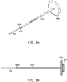
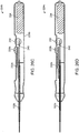
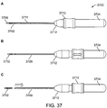
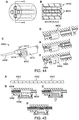
- FIGS. 2A-B , 3A-B , 4A-B, 5A-B , and 6A-E show simple nasal implant systems and variations for inserting an implant into a nasal tissue.
- FIGS. 2A-B and FIGS. 3A-B show a nasal implant system in use.
- FIG. 2A (perspective view) and FIG. 2B (longitudinal cross-sectional view) show a nasal implant system in preparation for, or in the process of moving through, nasal tissue for placing an implant in a nasal tissue. (Nasal tissue is not shown in this view).
- FIG. 3A (perspective view) and FIG. 3 (longitudinal cross-sectional view) show the same nasal implant system as it appears after the implant was placed in the nasal tissue.
- the nasal implant system may include a delivery needle, a stylet, and an implant.
- FIGS. 2A-B show a system 150 including a hollow delivery needle 152 for placing implant 104 into a nasal tissue.
- Hollow delivery needle 152 has piercing end 162 for penetrating the tissue for placement.
- Hollow needle 152 may be held or may be moved using needle knob 156, such as by pushing on needle knob 156 to insert needle 152 into a nasal tissue or pulling on knob 156 to remove needle 152 from nasal tissue and away from an implant.
- System 150 may include implant 104.
- Implant 104 may be pre-loaded into needle 152 prior to use by a physician or other user or may be loaded by a physician or other user into needle 152 at the time of treatment (e.g., at the time of a minimally invasive or non-invasive procedure).
- System 150 may also include a stylet 158 configured to fit inside needle 152.
- Stylet 158 may hold implant 104 inside hollow needle 152 or may hold implant 104 in a first position relative to the nasal tissue, such as when needle 152 is retracted away from implant 104.
- Stylet 158 may push implant 104 inside needle 152 to adjust a position of implant 104.
- stylet 158 may push implant 104 to initially place or to re-position it in needle 152, such as prior to needle 152 and implant 104 being placed into nasal tissue.
- Stylet 158 may push implant 104 into an implant insertion position such that distal end 168 of implant 104 is near piercing end 162 of needle 104.
- distal end 168 may be at the proximal side of the bevel on the piercing end.
- Needle 156 is moved through nasal tissue to an implant location.
- the depth of insertion of the needle into tissue may be indicated by marks 164 visible to the physician or other user. Such marks may, for example, be in increments of 1 mm for up to 30 mm. Because the depth of the needle in the tissue is indicated by the marks and the needle will be retracted away from the implant, the marks may precisely indicate the depth to which the implant will be placed.
- the physician or other user may receive tactile feedback from body tissue to determine when the needle is in place.
- the physician or other user may "feel” the needle hitting a hard object (e.g., a bone) or "feel” a change in the way the needle behaves.
- a hard object e.g., a bone
- the physician may "see” the position of a needle using imaging equipment.
- stylet 158 may push implant 104 into an implant implantation position such that distal end 168 of implant 104 may be at the distal-most side of the bevel on the piercing end.
- the movement of the distal end of the implant from the proximal side of the bevel to the distal side of the bevel may be movement between 0 mm and 10 mm, between 1mm and 7 mm, or between 2 mm and 4 mm.
- Hollow delivery needle 152 holding an implant 104 may be placed into nasal tissue.
- FIGS. 3A-B show the same nasal implant system as in FIGS. 2A-B as it appears after the implant was placed in nasal tissue. Structures changed in position in FIGS. 3A-B relative to FIGS. 2A-B are indicated by the addition of a lowercase letter ("a", "b”, etc.) after the corresponding reference numeral (such as 152a).
- needle 152b was retracted by moving (e.g., pulling) needle knob 156b away from implant 104 to leave implant 104 in the tissue in the same location as it was in while inside the needle.
- stylet knob 160 and needle knob 156b can be pulled (either together, or separately), removing the stylet and the needle from the tissue, leaving the implant in place in the tissue to improve (or maintain) nasal function and/or improve (or maintain) nasal appearance.
- needle 152 may be held still relative to implant 104.
- implant 104 may be pushed out of the needle by the pushing action of stylet 158 against the proximal end 166 of implant 104.
- implant 104 may be placed in the nasal tissue (e.g. removed from the needle) using both actions: retracting the needle away from the implant as well as pushing the implant away from the needle with the stylet.
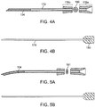
- FIGS. 4A-B show another embodiment of a nasal implant system for placing an implant into a nasal tissue similar to the nasal implant system shown in FIGS. 2A-B and FIGS. 3A-B with different control features.
- Needle knob 176a-176b comprises an elongated knob and may be grasped or held by a hand of a user or a finger and a thumb to move needle 172, as described above, into and out of nasal tissue. See also cross-sectional view 186.
- Stylet or pusher 178 may be grasped or held by a hand of a user (e.g. a different hand) or a finger and thumb of a user when the stylet is in place inside needle 172 to hold implant 104 in place while retracting needle 172 to place implant 104 into nasal tissue.
- FIGS. 5A-B show another embodiment of a nasal implant system implant for placing an implant into a nasal tissue similar to the nasal implant systems shown in FIGS. 2A-B and FIGS. 3A-B and FIGS. 4A-4B but with a contoured needle and with different control features.
- a contoured needle may be useful for placing a shaped (e.g. a contoured) implant into a nasal tissue (e.g. for placing an implant into an area that is hard to reach with a straight needle or for contouring the implant into the tissue to better support the tissue).
- a contoured implant may better conform to a tissue shape to provide support.
- a pre-formed contoured implant may be more effective at re-shaping a portion of a nasal tissue from a first shape to a second shape, such as by providing more force to the tissue.
- a contoured implant may provide better support (e.g. compared with an implant with a circular cross-section).
- FIG. 5A also shows the elliptical cross-sections 181 of the implant and needle.
- FIGS. 6A-E show another embodiment of a nasal implant system similar to the nasal implant systems described above.
- An implant and an inside of a needle may comprise (matching) elliptical cross-sectional shapes.
- the implants shown in FIGS. 6C-6E are pre-formed to have a curvature.
- Some implants may comprise a resilient material.
- Some implants may be temporarily deformed for a short time in a needle (e.g. a curved implant may be placed in a straight needle) in order for the needle to place the implant into a nasal tissue.
- Some examples provide a method of placing an implant in a tissue, including the steps of applying a force to an implant having a pre-delivery shape (or first shape) in a needle to hold it in a delivery shape (or second shape); placing the needle and the implant having the delivery shape into a nasal tissue; and removing the needle from the implant to thereby remove the force and allow the implant to return to its pre-delivery shape (first shape).
- the implant may include a soft barb to provide protection from movement, as described in more detail below.
- the needle cross section or shape provides for orientation of the implant.
- a system for placing an implant into a nasal tissue of a patient may include an assembly, including a grippable housing and a delivery conduit control mechanism, and a needle (or other implant delivery conduit such as a hollow implant delivery conduit) with a piercing end configured to pierce a body tissue, the conduit configured to hold an implant and to place the implant in a body tissue wherein a movement of the delivery conduit is controllable by the delivery conduit control mechanism.
- a system may allow the implant to be unsheathed from the needle once in position in the tissue. Such unsheathing may allow an implant to be placed with greater precision and control into a specific nasal tissue region.
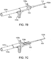
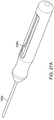
- FIG. 7A shows a configuration of a nasal implant system 100 with an assembly 101 and a hollow delivery needle 102 (or other hollow delivery conduit) for implanting an implant 104 into a nasal tissue.
- FIG. 7A shows the implant being loaded into the needle.
- FIGS. 7B and7C show other configurations of the same system during use for placing an implant in a nasal tissue.
- FIG. 7B shows an implant loaded in a needle and the needle advanced, just before needle retraction to place the implant in position.
- FIG. 7C shows the needle retracted away from the implant and the implant in position in the nasal tissue.
- a structure in a different position between related figures e.g. between FIGS.
- FIG. 7A shows loading an implant into the nasal implant assembly and moving the implant distally near the distal end of the needle.
- FIG. 7B shows inserting the needle into nasal tissue and advancing the implant distally to the distal end of the needle.
- FIG. 7C shows retracting the needle and placing (releasing) the implant into the tissue.
- FIG. 7A shows a hollow delivery needle with a proximal end (nearest the physician or other user) and a distal end (nearest the patient), the distal end having a piercing end 112 such that it can pierce and travel through nasal tissue to a desired implant location when a force is applied to the needle.
- Needle 102a is hollow and attached via a luer fitting 130 to a luer mating part (not visible in this view) of body 111 of the assembly. Prior to being attached to the body 111, a nasal implant was loaded into the proximal end of the needle.
- a system for placing an implant in a nasal tissue may further have a stylet (or other implant pusher member) for positioning the implant.
- the physician moves the stylet control lever 114a from a proximal to a distal position, which moves the stylet against the proximal end of the implant and pushes the implant near the distal end of the needle.
- the implant is placed at the base of the bevel (the shorter side of the bevel portion) of the piercing end 112 (distal end) of the needle. In other embodiments, the implant may be placed partway along the bevel.
- the end of the implant may be at the base of the bevel, or less than 1 mm, less than 2 mm, less than 3 mm, or less than 6 mm from the base of the bevel.
- the implant is now in a travel position in needle 102a and implant 104 to travel through nasal tissue to an implant position.
- Needle 102 also has a piercing end 112 on its distal end.
- Body 111 is held by a hand of a physician or other user to guide needle 102a, which holds implant 104, via the piercing end 112, through body tissue to the desired implant location in nasal tissue.
- having an implant near the end of the needle to at least partially block the needle opening reduces or prevents tissue coring (in which tissue is cored or collected inside the needle). Preventing or minimizing coring reduces patient pain and recovery time. Placing the implant at the base of the bevel without substantially protruding from the needle opening permits the beveled distal tip to perform its cutting function as the needle is advanced into tissue.
- the physician moves the stylet control lever 114a from a proximal to a distal position, which pushes implant 104 slightly further to the distal end of the needle (e.g. to the distal side of the bevel on the piercing end).
- This movement may be between 0 mm and 10 mm, between 1 mm and 7 mm, or between 2 mm and 4 mm. This additional movement places the implant close to or beyond the point to which the distal end of the needle as inserted into nasal tissue.
- the system may also include a needle control mechanism 108a (e.g., a delivery conduit control mechanism) for controlling movement of needle 102a.
- Needle control mechanism 106a retracts from a first position, shown in FIG. 7B , to a second position, needle control mechanism 106b, shown in FIG. 7C , so that it retracts needle 102a from a first position shown in FIG.7B , proximally away from implant 104, and into a second position in grippable housing 110, shown by needle 102b in FIG. 7C .
- the needle control mechanism may include a lever 108a configured for use by a physician or other user to control needle movement.
- Lever 108a may be moved from a first position (shown in FIG. 7B ) to a second position (see lever 108b in FIG. 7C ).
- a stylet (not visible in this view) may extend distally between the grippable housing 110 and may be at least partially disposed inside the hollow needle 102a or 102b.
- the stylet may connect with the proximal end of the implant and may control implant movement relative to the needle.
- the stylet may prevent the implant from moving proximally while the needle is being retracted. Instead, the stylet may keep the implant in the desired location as the implant is unsheathed from the needle (e.g., the needle is retracted away from the implant).
- such unsheathing means that the needle, specifically the piercing tip of the needle, which is designed to enter tissue and minimize tissue damage, is responsible for all tissue penetration.
- An implant does not need to be pushed or forced into position against nasal tissue. Tissue damage, patient pain, and healing times may all be reduced.
- control mechanism and the needle may move relative to the housing; that is, the housing remains in its position while the needle control mechanism and needle retract towards it or through it or partially through it.
- the assembly is configured so that the housing and the stylet-and the implant-can be held steady by the physician or other user while the needle moves so that the implant is placed in the desired location in the nasal tissue.
- the assembly may allow the physician or other user to readjust the needle after it is in place in the tissue.
- an implant may be loaded in the distal end of the needle.
- a needle may be pre-loaded with an implant, such as on its own or as part of a kit, before use by a physician or other user.
- an implant may be loaded into a needle by a physician or other user before performing a nasal implant procedure, such as a non-invasive or minimally invasive procedure.
- an implant may be loaded into a stylet channel through a side port (e.g. in the assembly body).
- a needle may (e.g., larger than 10 gauge, 10, 11, 12, 13, 14, 15, 16, 17, 18, 19, 20, 21, 22, 23, 24, 25, 26, 27, 28, 29, 30, 31, or 32 gauge, or smaller than 32 gauge).
- An implant may be sized to fit (e.g., fit tightly inside the needle). In some embodiments using a smaller needle may product less tissue damage. In some embodiments, a smaller needle may (better) fit into small areas of the nasal tissue (e.g., between the skin/mucosa and cartilage of the nose).
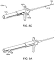
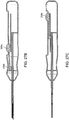
- FIGS. 8A-C show another embodiment of a system for placing an implant into a nasal tissue of a patient, related to the embodiment of FIGS. 7A-C .
- FIG. 8A shows a configuration of a nasal implant system 130 with an assembly 131 and a hollow delivery needle 102 (or other hollow delivery conduit) for implanting an implant 104 into a nasal tissue.
- FIG. 8A shows the implant being loaded into the needle.
- FIGS. 8B and8C show other configurations of the same system during use for placing an implant in a nasal tissue.
- FIG. 8B shows an implant loaded in a needle and the needle advanced, just before needle retraction to place the implant in position.
- FIG. 8C shows the needle retracted away from the implant and the implant in position in the nasal tissue.
- FIG. 8A shows a configuration of a nasal implant system 130 with an assembly 131 and a hollow delivery needle 102 (or other hollow delivery conduit) for implanting an implant 104 into a nasal tissue.
- FIG. 8A shows the implant
- FIG. 8A shows loading an implant into the nasal implant assembly and moving the distal end of the implant near the distal end of the needle.
- FIG. 8B shows inserting the needle into nasal tissue and advancing the implant distally to the distal end of the needle.
- FIG. 8C shows retracting the needle and placing (releasing) the implant into the tissue.
- the detailed description of the implant loading, implant advancement to the distal end of the needle, placement of the needle and implant into nasal tissue, and retraction of the needle to place the implant into the nasal tissue and in contact with the nasal tissue is as described above for FIGS. 7A-C . Changes relative to FIGS. 7A-C include the shape and orientation of stylet control lever 144a, 144b and the shape and orientation of needle control mechanism 137a, b.
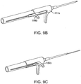
- FIGS. 9A-C a system for placing an implant into a nasal tissue of a patient.
- FIGS. 9A-C show another embodiment of a system for placing an implant into a nasal tissue of a patient, related to the embodiment of FIGS. 7A-C and FIGS 8A-C .
- FIG. 9A shows a configuration of a nasal implant system 130 with an assembly 131 and a hollow delivery needle 102 (or other hollow delivery conduit) for implanting an implant 104 into a nasal tissue.
- FIG. 9A shows the implant being loaded into the needle.
- FIGS. 9B and 9C show other configurations of the same system during use for placing an implant in a nasal tissue.
- FIG. 9B shows an implant loaded in a needle and the needle advanced, just before needle retraction to place the implant in position.
- FIG. 9C shows the needle retracted away from the implant and the implant in position in the nasal tissue.
- FIG. 9A shows loading an implant into the nasal implant assembly and moving the distal end of the implant near the distal end of the needle.
- FIG. 9B shows the configuration of the system while inserting the needle into nasal tissue and advancing the implant distally to the distal end of the needle.
- FIG. 8C shows the configuration of the system while retracting the needle and placing (releasing) the implant into the tissue.
- the detailed description of the implant loading, implant advancement to the distal end of the needle, placement of the needle and implant into nasal tissue, and retraction of the needle to place the implant into the nasal tissue and in contact with the nasal tissue is as described above for FIGS. 7A-C . Changes relative to FIGS. 7A-C include the shape and orientation of stylet control lever 184a, 184b and the shape and orientation of needle control mechanism 177a, b.
- implant 104 may be moved inside assembly 101 or moved inside needle 102 or may be held in place inside assembly 101 or inside needle 102.
- An end of implant 104 may be held by the stylet.
- Needle 102 may be further internally configured to hold implant 104 such as by tight fit with an implant.
- the tight fit may be "just right"-a friction fit sufficiently tight to hold the implant inside the needle, but loose enough to allow the force from a stylet or other pusher to hold the implant in place during needle retraction to place the implant into nasal tissue.
- a delivery needle can be retracted away from an implant in order to place the implant into the nasal tissue without the need for a mechanism to hold the implant or a mechanism or cutting tool to release the implant from the needle.
- a "just right” friction fit may also be helpful for holding the implant in the needle, such as in a kit.
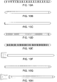
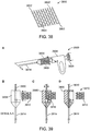
- FIGS. 10A-J show various embodiments of implants. Any of these implants may be used with any of the systems, assemblies, and devices and with any of the methods described herein or an implant may be used with other system, assembly, or device described elsewhere.
- Such implants may be useful for placing in a body tissue, such as nasal tissue.
- a generally longitudinal resilient implant comprising: a first end, a second end and a length therebetween, the implant comprising a surface feature along the length.
- an implant is configured to provide an implant flexural rigidity between 2.5e-6, and 1.5e-5.
- an implant is configured to provide an implant flexural rigidity between 2.5e-6, and 1.5e-5 after being in contact with a body tissue for at least 3 months, for at least 6 months, for at least 9 months, or for at least one year.
- an implant include one or a plurality of surface features (such as, e.g., a fin, a notch, a rib, or a scallop. Some embodiments of an implant comprise a resorbable feature (such as, e.g. PLLA-PDLA in a ratio from 90:10 to 50:50. Some embodiments include an implant with a bend, with an angle greater than 0 degrees and less than 45 degrees, less than 35 degrees, less than 25 degrees, or less than 15 degrees. Some embodiments include an implant less than 30 mm, less than 25 mm, less than 20 mm, or less than 15 mm. Some embodiments include an implant with a diameter (e.g. an outer diameter) configured to form a tight fit within a 16 gauge needle.
- a diameter e.g. an outer diameter
- an implant has an outer diameter less than 1.5 mm, less than 1.2 mm, less than 1.0 mm or between 0.8 and 1.2 mm.
- an implant comprises a color that is not readily visible through skin (e.g. skin-tone, tan, brown, etc.).
- an implant comprises a radiopaque material.
- An implant may preserve its shape; may be strong, yet flexible; it may be similar to cartilage in such properties.
- Another aspect of the invention includes a generally longitudinal implant having a first end, a second end, and a length there between, the first end comprising an end feature.
- the second end comprises an end feature.
- the first end feature and the second end features may comprise the same configuration.
- the first end feature and the second end features may comprise different configurations.
- an end feature is configured to mate with a pusher tool.
- an end feature comprises an ellipse.
- an end feature comprises an expansion feature, such as tines or fins.
- An expansion feature may be useful, when inserted into a nasal tissue, for preventing the implant from moving, such as, for example, from moving into the path or space left after a removal of a needle that placed the implant in the tissue.
- An expansion feature may be useful for anchoring the implant to a bone or to cartilage.
- an implant with an elliptical distal end may allow seating of the implant against a bone at any angle.
- An end feature may be useful for fixing an implant together with a tissue.
- One or more than one surface features may be useful for fixing an implant together with a tissue.
- an adjustable implant e.g. adjustable for an individual patient.
- a shape of an implant is conformed in situ to a shape of a nasal tissue.
- a particular length of an implant can be chosen based on an individual's nasal structure size(s).
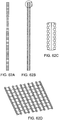
- FIG. 10A shows an implant comprising scallops such as a series of circular segments or angular projections.
- scallops, segments or projections may provide additional surface area (e.g. for tissue interaction) to reduce or prevent implant movement (such as backing out of the implant into an incision or needle insertion site).
- implant movement such as backing out of the implant into an incision or needle insertion site.
- Such scallops, segments or projections may be used to provide an indication of length and to provide stability during implant cutting.
- FIG. 10B shows an implant comprising an elliptical first end and an elliptical second end.
- An elliptical end may provide greater surface area to rest against a tissue at any angle.
- FIG. 10C shows an implant comprising an elliptical first end (semi-elliptical).
- An elliptical end may provide greater surface area to rest against a tissue at any angle.
- FIG. 10D shows an implant comprising a plurality of ribs and a conical first end and a conical second end.
- An implant may include one rib or more than one rib.
- Such ribs may include alternating raised regions and depressed regions (valleys) with smooth transitions between the a rib and a depression (valley).
- a conical end may provide greater surface area to rest against tissue at any angle when an implant is in place in a tissue.
- a rib(s) along the shaft may provide additional surface area for the tissues to adhere.
- a valley of ribs may provide stability when cutting an implant.
- FIG. 10E shows an implant comprising a plurality of fins and a conical end (as described above).
- One or more than one fin may provide additional surface area for tissue to adhere to the implant.
- a valley of fins may provide stability during implant cutting.
- FIG. 10F shows an implant with a first semi-elliptical end and a second end with a concave end feature.
- a concave end feature may allow tissue to embed within the implant.
- a concave end feature may mate with a corresponding (e.g. elliptical) shape on an insertion tool (e.g. a stylet, a pusher).
- FIG. 10G shows an implant with a first semi elliptical end and a plurality of notches (e.g. along one side or one region of the implant).
- One or more than one notch may provide leverage to reduce or prevent implant movement (such as backing out of the implant into or through an incision or needle insertion site).
- One or more than one notch may provide stability during cutting and indication of implant length (e.g. for implant cutting).
- FIG. 10H shows an implant with a first semi-elliptical end and a second end with an expansion feature(s).
- a concave expansion feature may allow tissue to embed within the implant.
- a concave end feature may mate with a corresponding (e.g. elliptical) shape on an insertion tool (e.g. a stylet, a pusher).
- the flared geometry may be compressed within an insertion tool (e.g. needle) and expanded or allowed to expand after being placed in tissue.
- Such an expansion feature may provide leverage to reduce or prevent implant movement (such as backing out of the implant into or through an incision or needle insertion site).
- FIG. 10I shows an implant with a first semi-elliptically shaped end and a second end with a plurality of tines.
- One or more than tine on an implant end may be compressed within the insertion tool (needle).
- the tine or tines may expand and provide leverage for the implant.
- Such an expansion feature may provide leverage to reduce or prevent implant movement (such as backing out of the implant into or through an incision or needle insertion site).
- FIG. 10J shows an implant with a first conical end and a second conical end and a plurality of modified fins along the shaft.
- the modified fins show a (continuous) progression from a shorter length to a longer length from a first region (which may a first end region) to a second region (which may be a second end region).
- Such modified fins may provide additional surface area for the tissue to adhere.
- a valley of fins may provide stability when cutting an implant and may provide an indication of implant length (e.g., for implant cutting).
- a ribbed implant or an implant with a regular, repeating pattern comprising a biodegradable material may provide a controlled degradation pathway.
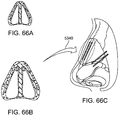
- FIG. 10K-N show cross-sectional views of various embodiments of an implant.
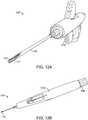
- FIG. 11 and FIGS. 12A-C shows other systems for placing an implant into a nasal tissue of a patient.
- Such systems may include an assembly comprising a grippable housing and a delivery conduit control mechanism, and a needle (or other hollow implant delivery conduit) configured to hold an implant and to place the implant in the nasal tissue, the needle further having a piercing end to pierce body tissue for moving the needle through the body tissue.
- FIG. 11 shows another configuration of a nasal implant system 500 with an assembly 501 and a hollow delivery needle 102 (or other hollow delivery conduit) for implanting an implant 104 into a nasal tissue.
- FIGS. 12A-C show a similar nasal implant system 520 with a style control knob variation that can be used to push an implant into a needle (e.g. into a proximal end of a needle prior to attachment of the needle to the assembly.
- Nasal implant system 500 or nasal implant system 520 may include an unsheathing option to thereby more precisely place an implant into a particular nasal tissue.
- FIG. 11 and FIG. 12A-C show the configuration of the system during steps in placing an implant into a nasal tissue.
- FIG. 11 and FIG. 12A-C show the configuration of the system during steps in placing an implant into a nasal tissue.
- implant 104 has a proximal end (closest to the physician or other user; not readily visible in this view) and a distal end 168. Implant 104 had previously been loaded into the proximal end of delivery needle 102 and the proximal end of delivery needle 102 connected with grippable housing 510. Implant 104 had been distally advanced by being pushed through needle 102 with a stylet (e.g.
- implant control knob 508 by a physician or other user to sit close to piercing end 112 of needle 102 under control of implant control knob 508, and held close to piercing end 112 of the needle.
- Delivery needle 102 with implant 104 held near its piercing end 112 had then been placed in body tissue (e.g. nasal tissue) and advanced through body tissue (e.g. through nasal tissue or surrounding tissue) to place piercing end 112 of needle 102 at a distal-most end of the desired implant location. Once the piercing end 112 of needle 102 was in place, implant 104 had been further distally advanced to be placed at the very distal end of needle 102 (e.g. at the distal end of the bevel).
- the implant is ready to be placed into the nasal tissue and the implant can be unsheathed from the needle.
- a user grabs or holds the hand grip 512.
- the user places a first finger on (the distal portion) of first trigger member 502 and a second finger on (the distal portion) of second trigger member 504.
- a user presses safety button 514 to allow needle 102 movement.
- the user pulls on the first trigger member and second trigger member to thereby withdraw the needle into grippable housing 510 and to unsheath implant 104 in place in the tissue.
- Assembly 501 is then withdrawn from the nasal tissue, leaving the implant in place.
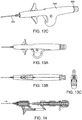
- FIGS. 13A-C show engineering views of one embodiment of a device similar to that shown in FIG. 11 and FIGS. 12A-C .
- FIGS. 14 and 15 shows a side views and inner workings of an embodiment of an assembly similar to the assemblies shown in FIG. 11 , FIGS. 12A-C , and FIGS. 13A-C .
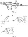
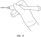
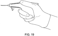
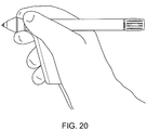
- FIGS. FIGS. 14-21 show various embodiments of grippable housings, hand grips, and triggers, including a single trigger, a double trigger, a "pencil grip" embodiment and a pistol grip embodiment. In some embodiments, a double trigger and pistol grip are combined.
- the assembly/handgrip is configured to allow a single person to perform various actions (e.g.
- the assembly/grip is configured to be usable by either a right-handed or a left-handed person (e.g., without making any changes to the assembly/handgrip).
- the assembly is configured to place the implant with no more than 10 N. In some embodiments, the assembly is configured to retract with no more than 10 N.
- Shaping an implant in vivo may allow the shape of the implant to be custom fit (sized and shaped) to the nasal anatomy to better address the condition that is being corrected by the implant. Shaping an implant in vivo (e.g. to a nonlinear shape) may also reduce tissue damage by, for example, allowing a smaller needle to be used for implant insertion.
- Use of a custom shaped implant may provide an advantage such as providing a larger reshaping surface, providing an increased level of support to a tissue in need of support, reducing the likelihood of extrusions (e.g., the implant being pushed out of place), or reducing the likelihood of the explant being externally visible.
- a custom formed implant may provide an advantage
- One obstacle is how to provide energy to an implant so that the implant becomes responsive to being shaped.
- Another obstacle is how to minimize tissue damage that might be due to a system or device used for shaping or delivering energy.
- Another obstacle is how to prevent nasal tissue from being damaged by an energy provided for shaping an implant.
- Another obstacle is how to remove any energy delivery elements or shaping devices while preventing or minimizing damage to nasal tissue.
- Another obstacle is how to reshape implant that is disposed inside a nasal tissue when the implant is not readily accessible to a physician or other individual.
- Another obstacle is what to do if an implant is initially formed into an undesired shape.
- An implant may be heated by external heating/conduction heating. After implant insertion, heat is applied through conduction directly to the patient's nose with a heater tool either from inside the nostril, outside the nostril, or both simultaneously. A heater tool may be used to apply force to shape the implant.
- An implant may be heated by external heating/alternate heating in which heat is applied directly to the patient's nose with a heater tool either from inside the nostril, outside the nostril, or both simultaneously.
- the source of heat may be, for example, ultrasonic or microwave.
- An implant may be heated with a pre-heated cannula heater, as described below. After insertion the needle tip is heated. This heats the implant and the local tissue to reduce cooling of the implant. The needle is removed and the implant is quickly shaped (freeform shaping).
- An implant may be heated by internal heating/cannula heater as described below. After insertion, the needle is retracted exposing a heater at the end of a cannula. This heats the implant at the end of cannula. The heater is pulled off the implant as it is shaped. An integrated insertion tool and heater tool may be used; shaping can occur simultaneously with implantation.
- An implant may be heated with a flexible heater/ribbon heater as described below. A flexible heater element encapsulates the implant. Both components are inserted together into the patient. After needle retraction, the flexible heater is heated and the implant shaped. The flexible heater is then removed. The heater may be a flexible ribbon heater wrapped around the implant. Insulation material may be present to protect internal tissue.
- the insertion tool and heater may be integrated together.
- An implant may be heated using internal heating/flexible heater/coiled wire as described below.
- the flexible heating element may be located in the center of the implant.
- the heater can be a resistive heater or a thermal conductor. Both components may be inserted together into a patient. After needle retraction, the flexible heater may be heated and the implant shaped.
- Any form of energy that allows an implant to be shaped may be used (e.g. heat, microwave, ultrasonic). Any form of energy delivery to the implant that allows or causes a change in the implant may be used.
- energy may be delivered from outside the nose (such as, e.g., by conduction, or by ultrasonic waves or microwaves.
- Energy may delivered from inside the nose, such as by a heater heating an end of an implant, a heater heating a side of an implant, a heating an inside of a nose.
- a system for shaping an implant in a tissue in a body includes a grippable housing comprising a delivery conduit control mechanism; a hollow implant delivery conduit with a piercing end, the conduit connected with and its movement controllable by the delivery conduit control mechanism, the conduit configured to hold an implant, pierce a body tissue with the piercing end, and place the implant in the tissue; an energy delivery element configured to deliver energy to the implant when the implant and the energy delivery element are in place in the tissue; an energy source for delivering energy to the energy delivery element; and an energy source controller configured to control the energy delivered to the energy delivery element from the energy source.
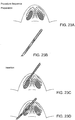
- FIG. 22 shows a portion of a system 188 for shaping an implant in a tissue in a body and FIGS. 23A-C show steps in shaping a nasal implant in a nasal tissue using such a system.
- the system and method use a heating element between the implant and stylet and carried into the nasal tissue using a delivery needle.
- FIG. 22 shows implant 104 disposed in a needle 102, as they would appear in position in a tissue, ready for unsheathing of the implant by the needle to place the implant in place in the tissue.
- Implant 104 comprises a heat responsive material (e.g., an energy responsive material), such that implant 104 may become more flexible upon exposure to heat.
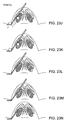
- FIGS. 23A-N show steps in inserting a heat responsive implant into a tissue, and changing a shape of the implant.
- FIGS. 23A-B show preparation steps.
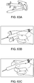
- FIG. 23A shows a physician examining the nose to find the optimal position for the implant, and applying anesthesia to the patient near the insertion site. The physician waits for the anesthesia to take effect and cleans the surface of the insertion site with an antiseptic solution.
- FIG. 23B shows the implantation tool is made ready, removing it from sterile packaging.
- FIGS. 23C-I show insertion steps.
- FIG. 23C shows the needle tip of the implantation tool is inserted into the nose of the patient by the physician.
- FIG. 23D shows the needle is carefully navigated through the nasal tissue to ensure the path is in the correct position.
- the depth of the needle is monitored via visual cues integrated on the outside shaft. The depth is dictated by location of implant to bone. The location of the implantation tool can still be slightly altered up, down, right, and left.
- FIG. 23E shows that once at the correct depth and location, the needle is released and allowed to move relative to the stylet and implant.
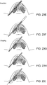
- FIG. 23F shows the needle is removed from around the implant while the implant and stylet remained fixed.
- FIG. 23G shows the implant remains inside of the nasal tissue with the heating element interfacing with the implant.
- FIG. 23H shows the heater is activated and allowed to reach the correct temperature.
- FIG. 23I shows the heater warms the implant to allow it to become softened at the locations that need to be modified.
- FIGS. 23J-N show implant shaping.
- FIG. 23J shows that once the implant is moldable, the implant is shaped by applying pressure with the shaping instrument.
- FIG. 23K shows that the heater is turned off and the shape of the implant is set by allowing it to cool.
- FIG. 23L shows the shape of the implant is verified and additional heating and shaping are applied if needed.
- FIG. 23M shows that with the stylet still engaged, the heating element is removed from around the implant.
- FIG. 23N shows the stylet and the implantation tool are removed from the patient. The custom shaped implant remains in the nasal tissue.
- a method of shaping an implant in a tissue may include the steps of placing an energy-response implant having a first shape into a nasal tissue; inserting an energy delivery element into an individual's nose; delivering energy from the energy delivering element to the implant to thereby increase a flexibility of the implant; shaping the implant into a second shape; and removing energy from the implant to thereby hold the implant in the second shape.
- Using such system or method may allow an implant to conform to a body tissue during shaping to provide a precise fit between an implant and a body tissue.
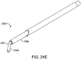
- FIGS. 24A-E shows another embodiment of a system 200 for shaping an implant using energy in a tissue in a body.
- FIG. 24A shows implant 104(a) is disposed inside cannula heating element 198a which in turn is disposed inside needle 1196a for the needle to deliver the cannula heating element and the implant to a desired implant tissue location for an implant in a nasal tissue.
- needle 196a is retracted, as shown in FIG. 24C , unsheathing and leaving cannula 198a and implant 104a surrounded by cannula 198a in the desired implant tissue location.
- cannula 198b may be retracted, unsheathing and leaving heated (flexible) implant 104(a) in the desired tissue location.
- Implant 104b may be quickly shaped such as creating implant bend 206. Any external pressure (e.g., a tool pressed against an outside of the nose, or an internal pressure (e.g., a tool pressed against an inside of a nose) may be used to custom shape the implant to the nasal tissue.
- the needle may remain in position around the cannula during the heating steps.
- the needle and cannula may comprise a single unit.
- Steps in the method of using such a heating element may include: placing a hollow delivery conduit encompassing an implant in the nasal tissue, the implant having a first shape; heating a portion of the delivery conduit to thereby heat the implant; after the heating step, shaping the implant into a second shape; and retracting the conduit from the nasal tissue and from the implant to thereby place the implant in contact with the nasal tissue.
- the delivery conduit comprises an internal portion (cannula) comprising insulation, and the method further comprising insulating the nasal tissue from the
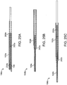
- FIGS. 25 A-C show another embodiment of a system 196 for shaping an implant using energy in a tissue in a body.
- the system is a central axis heater, configured to deliver energy to an implant from an inside (center) of the implant.
- Energy responsive implant 198 has a hollow inside for accepting a heating element 204, which may be, for example, a rod or wire (e.g., a resistive wire, a thermally conductive rod).
- a resistive wire may allow an implant to be uniformly heated across its length.
- FIG. 25A shows a system 196 during insertion into a nasal tissue with needle 102a encompassing implant 198a which in turn encompasses heating element 204. (The system maintains the same configuration it had just prior to being inserted into the nasal tissue).
- needle 102b is retracted, unsheathing implant 198a.
- the heater is activated until the implant is above Tg. Once above Tg, the implant is freely shaped. When the desired shape is achieved, the heater is deactivated, allow the implant to cool below Tg (which may be less than, for example, 20 seconds).
- Tg which may be less than, for example, 20 seconds.
- the heater element inside the heater element is retracted while the back of the implant is held in place, as shown in FIG. 25C . The device is then retracted off the implant.
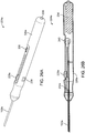
- FIGS. 26A-D show another embodiment of a system 224 for shaping an implant using energy in a tissue in a body, an integrated implanting and heating system with a central axis heater.
- the system integrates implanting manipulation functions including needle retraction and heating functions including heating control and heater retraction into a single housing.
- the system may be used with any implant or heat system, but may be especially useful with an implant system with a central axis heater for heating an implant, such as the one described in FIGS. 25A-C .
- FIG. 26A shows a perspective view and FIG. 26B shows a cross-section view of the system during implant delivery and before heating.
- FIG.26C shows a section view of the system after retracting the needle, but before heating and shaping are completed.
- System 224 has a grippable housing 226.
- System 224 includes a heater on/off switch 236 for controlling the heat to the heater, a battery 234 (e.g., energy source) for providing heat to the heater, and an LED indicator light 238 to indicate when shaping can occur.
- System 224 further includes a needle retraction button 228 which controls a slider retraction mechanism 232 for connecting with and retracting the needle away from the implant (desheathing) after the implant has been placed in position in the tissue.
- System 224 further includes a heater retraction knob 230 connected with a pulley mechanism for retracting the heater.
- FIGS. 26A and 26B show the steps of inserting needle 102 to a desired location in a nasal tissue; and unlocking needle retraction button 228a.
- FIG. 26C shows sliding needle retraction button 228b to end of travel to retract the needle and unsheath the implant.
- FIG. 26C also illustrates the steps of turning on heater on/off button 236, waiting for LED indicator light 238 to turn on, indicating an implant is ready to be shaped from a first shape to a second shape by activating LED indicator light 238, shaping implant into a second shape (not readily seen in this view).
- FIG. 26D illustrates indicating that an implant is sufficiently cooled (e.g. for an implant to hold its second shape), turning the heater retraction knob 230 to activate pulley retraction mechanism 240 and retracting heater 204a out of implant 104. Finally, the assembly is removed from the nasal tissue.
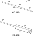
- FIGS. 27A-G and FIG. 28 show another embodiment of a system 242 for shaping an implant using energy in a tissue in a body.
- the system separates implanting manipulation functions including needle retraction in a first housing, heating functions including heating control and heater retraction into a second housing and battery and heat control into a third housing.
- the system may be used with any implant or heat system, but may be especially useful with an implant system with a central axis heater for heating an implant, such as the one described in FIGS. 25A-C .
- FIG. 27A shows a perspective view and FIGS. 27B-C show cross-sectional views of the needle control housing during use.
- FIG. 27D-G show views of the heating and retraction device during use.
- FIG. 28 shows a view of the battery and heat control housing.
- System 242 has a first grippable housing 244 for controlling a needle.
- System 242 includes a first grippable housing 244 including a needle retraction button 228 which controls a slider retraction mechanism 232 for connecting with and retracting the needle away from the implant (desheathing) after the implant has been placed in position in the tissue.
- System 242 includes a second grippable housing 246 including a heating and retracting device.
- System 242 includes third housing 248 with a heater, a heater on/off switch 236 for controlling the heat to the energy delivery element, a battery 234 for providing heat to the heater, and an LED indicator light 238 to indicate when shaping can occur and when the implant has cooled sufficiently to hold its shape.
- FIGS. 27A and B show steps of inserting needle 102 into nasal tissue and unlocking needle retraction button 228.
- FIG. 27C shows the steps of sliding needle retraction button 228 to the end of travel and locking the needle retraction button.
- FIGS. 27C and D show removing the implanting device from the heater and implant by twisting away and leaving energy responsive implant 198 attached to frame 250, including electrical contact 252 and threaded rod 254 for heater retraction.
- FIGS. 27E and F show attaching heating and retraction device 246a to implant and heater 254.
- FIG. 27G shows a section view of an implant, heater, and retraction device with the heater retracted.
- FIG. 28 shows the third housing with battery pack and heater controller 248 which can be attached by electrical wires 239 to heating and retraction device 246.
- the third housing with battery pack and heater controller 248 is turned on using heater on/off button 236. Once LED indicator light 238 turns on, implant 198 is shaped (such as described elsewhere). After LED indicator light 238 turns off, a heater retraction knob on the second grippable housing-implant, heating and retraction device 246 is turned to moved threaded rod 254 (shown in FIG. 27D ) and retract heater out of the implant, as shown in FIG. 27F .
- An energy source may raise the temperature of the implant above its glass transition temperature (Tg) so that it can be shaped. When a material is above its Tg, it can be freely shaped. When the material temperature falls below the Tg, a material will hold its shape.
- Tg glass transition temperature
- Any of the any of the above described systems, assemblies, or methods may use a heater tool to apply force to shape an implant. After shaping, the heating tool may be removed.
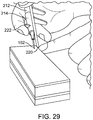
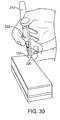
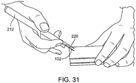
- FIGS. 29-31 show an assembly 212 including a housing support member 216 connected with grippable housing 214, with distal end 220 of support member configured to abut a patient's face during support member use.
- a housing support member may help hold assembly 212 in place (e.g. with minimal or essentially no movement) on the patient's face during assembly use, such as while retracting the needle away from the implant; this keeps the implant in a desired implant location during needle retraction.
- a housing support member may be an extension from the distal face of the assembly.
- a housing support member may be slidable from the body of the delivery tool.
- a housing support member may be spring loaded (e.g., comprising a rigid spring).
- steps in using a housing support member may include moving the housing support member to contact a face of a patient, and locking the housing support member in place.
- steps in using a housing support member may include moving the housing support member to contact a face of a patient, and sliding the housing support member proximally while inserting the needle in the nasal tissue.
- a method of implanting an implant into a nasal tissue of a patient may include the step of contacting the housing support member with a face of a patient to thereby hold the housing in place on the face of the patient during the retracting the delivery conduit from the implant step.
- a physician or other user may pull on trigger 222 to retract needle 102 (e.g., retract needle 222 proximally) out of the tissue.
- the needle may be retracted relative to housing 214 and relative to housing support member 216. Housing 214 and housing support member 216 may remain stationary (e.g., not move relative to one another) during the needle retraction step.
- An assembly for placing an implant in a nasal tissue may further comprise a support member connected with the housing, the support member configured to abut a portion of a face of a patient when an assembly is in use on the patient.
- FIGS. 32A-D show a nasal implant system 3200 according to yet another embodiment of this invention.
- the system has a grippable housing 3204 supporting an implant holder 3206.
- An implant 3202 such as, e.g., one of the implants described with respect to FIGS. 10A-N above, is loaded into the implant holder 3206, and a needle 3208 (such as, e.g., a 16 g beveled hypodermic needle) is attached to the housing over the implant via internal threads on needle actuator 3220.
- a needle 3208 such as, e.g., a 16 g beveled hypodermic needle
- a piston 3210 is slidably disposed within a bore 3212 of housing 3204, and a handle 3214 extends from piston 3210 to the underside of housing 3204.
- a pusher 3216 extends from piston 3210 into implant holder 3206. Movement of handle 3214 toward a stationary handle 3218 advances the pusher 3216 through the implant holder 3206 to push the implant 3202 distally into needle 3208. When the two handles meet, the distal end of implant 3202 is at the beveled opening of needle 3208, as shown in FIG. 32D .
- the needle 3208 may be retracted from the implant 3202 by moving the needle actuator 3220 proximally to the position shown in FIG 32B .
- handle 3214 may be moved further distally after insertion of the needle into nasal tissue but before retraction of the needle to push the implant further distally, e.g., to the distal end of the needle's beveled opening.
- An opening 3222 in the distal portion of the housing enables the user to observe and confirm needle retraction.
- FIGS. 33A-C show a nasal implant system 3300 according to another embodiment of this invention.
- the system has a housing 3304 supporting an implant holder (not shown).
- An implant 3302 such as, e.g., one of the implants described with respect to FIGS. 10A-N above, is loaded into the implant holder, and a needle 3308 (such as, e.g., a 16 g beveled hypodermic needle) is attached to the housing over the implant via internal threads on needle actuator 3320.
- a needle 3308 such as, e.g., a 16 g beveled hypodermic needle
- an implant actuator 3310 extends proximally from the housing.
- a pusher 3316 extends distally from the implant actuator 3310 through the housing to the implant holder. Distal movement of the implant actuator 3310 toward the housing moves the pusher toward the implant and the implant out of the implant holder and into the needle to place the distal end of the implant at the beveled opening of the needle. Thereafter, proximal movement of the needle actuator 3320 retracts the needle from the implant while the pusher holds the implant stationary, as shown in FIG. 33C .
- a rotary dial 3314 may be turned after insertion of the needle into nasal tissue but before retraction of the needle to push the implant further distally, e.g., to the distal end of the needle's beveled opening.
- a ring grip 3318 extending from the housing assists in holding the housing stably.
- FIGS. 34A-C show a nasal implant system 3400 according to yet another embodiment of the invention.
- the system has a housing 3404 supporting an implant holder (not shown).
- An implant 3402 such as, e.g., one of the implants described with respect to FIGS. 10A-N above, is loaded into the implant holder, and a needle 3408 (such as, e.g., a 16 g beveled hypodermic needle) is attached to the housing over the implant via internal threads on needle actuator 3420.
- a needle 3408 such as, e.g., a 16 g beveled hypodermic needle
- an implant actuator 3410 extends proximally from the housing.
- the implant actuator may have, e.g., a ring or cap at is distal end as shown in FIGS. 34A and 34B , respectively.
- a pusher 3416 extends distally from the implant actuator 3410 through the housing to the implant holder. Distal movement of the implant actuator 3410 toward the housing moves the pusher toward the implant and the implant out of the implant holder and into the needle to place the distal end of the implant at the beveled opening of the needle, as shown in FIG. 34C . Thereafter, proximal movement of the needle actuator 3420 retracts the needle from the implant while the pusher holds the implant stationary, as shown in FIG. 34C .
- the implant actuator may be moved further distally after insertion of the needle into nasal tissue but before retraction of the needle to push the implant further distally, e.g., to the distal end of the needle's beveled opening.
- Handles 3414 and 3418 extend from the housing to assist in holding the housing stably.
- FIGS. 35A-C show a nasal implant system 3500 according to still another embodiment of the invention.
- the system has a housing 3504 supporting an implant holder (not shown).
- An implant 3502 such as, e.g., one of the implants described with respect to FIGS. 10A-N above, is loaded into the implant holder, and a needle 3508 (such as, e.g., a 16 g beveled hypodermic needle) is attached to the housing over the implant via internal threads on needle actuator 3520.
- a needle 3508 such as, e.g., a 16 g beveled hypodermic needle
- an implant actuator 3510 extends proximally from the housing.
- a pusher 3516 extends distally from the implant actuator 3510 through the housing to the implant holder.
- Sliding movement of the implant actuator 3510 within a track in the housing to the position shown in FIG. 35C moves the pusher into and the implant out of the implant holder and into the needle to place the distal end of the implant at the beveled opening of the needle.
- proximal movement of the needle actuator 3520 retracts the needle from the implant while the pusher holds the implant stationary, as shown in FIG. 35C .
- the implant actuator may be moved further within the track in the housing after insertion of the needle into nasal tissue but before retraction of the needle to push the implant further distally, e.g., to the distal end of the needle's beveled opening.
- a ring or handle 3518 extends from the housing to assist in holding the housing stably.
- FIGS. 36A-F show a nasal implant system 3600 according to another embodiment of the invention.
- the system has a housing 3604 supporting an implant holder (not shown) and a pistol grip 3613 having a proximal pistol grip skin 3613 and a distal trigger skin 3623.
- An implant 3602 is loaded into the implant holder, and a needle 3608 (such as, e.g., a 16 g beveled hypodermic needle) is attached to the housing over the implant via internal threads on needle actuator 3620, such as via luer 3621.
- the implant 3602 may be formed from a bio-absorbable material that may include various combinations of PLA, PDLA, PDS, PLC, PGA, PLG or similar. As shown in FIG.
- implant 3602 is substantially round in cross section and approximately 25 mm in length.
- the implant has barbed or tined features 3631 at the distal end. These features may be made by cutting into the implant with a blade at a 30-45 degree angle, then bending the outer portion of the implant material to its plastic deformation point. These barbs would be flexible enough to collapse inward (i.e., into the original position prior to barb formation) when introduced into needle 3608 and resilient enough to expand when the implant is released from the needle into nasal tissue.
- Implant 3602 also has proximal length markers 3627 and a proximal cup face 3625.
- a plunger-shaped implant actuator 3610 extends proximally from the housing.
- a pusher 3616 extends distally from the implant actuator 3610 through the housing to the implant holder (through the proximal handle core 3611).
- the distal face of the pusher 3616 is concave to mate with the rounded proximal end of the implant to, e.g., center the implant on the pusher.
- Distal movement of the implant actuator 3610 (such as with plunger head 3609) toward within the housing from the position shown in FIG. 36A to the position shown in FIG. 36E moves the implant out of the implant holder and into the needle to place the distal end of the implant at the beveled opening of the needle.
- proximal movement of the needle actuator 3620 retracts the needle from the implant while the pusher holds the implant stationary, as shown in FIG. 36F .
- a handle 3618 extends from the housing to assist in holding the housing stably.
- a window 3605 in housing 3604 permits the barbs to remain extended until the implant is loaded into the needle. This feature enables the implant to remain in the system for an extended period of time (e.g., during packaging, sterilization, transportation and inventory storage) without an adverse effect on the position and resilience of the barbs due to polymer creep.
- FIGS. 37A-C show a nasal implant system 3700 according to yet another embodiment of the invention.
- System includes a substantially cylindrical main body 3704, a slidable ring trigger 3710, a rod-like piercing element 3708 extending through a tool shaft 3709, and a hollow implant 3702.
- This nasal implant delivery tool is configured to deliver the hollow rod implant 3702 to the nasal anatomy in a similar manner to the systems discussed above.
- the piercing element 3708 extends through the hollow implant 3702 and retains the implant with a friction fit. The proximal end of the implant rests against the distal surface of the tool shaft.
- the entire tool may be retracted to deposit the implant at its target location.
- the implant 3702 may have barbs, as discussed above that interact with nasal tissue to maintain the implant in position as the delivery tool is retracted.
- the tool and implant are inserted into nasal tissue in the configuration shown in FIG. 37A .
- the trigger ring 3710 is retracted, as shown in FIG. 37B , thereby releasing the implant 3702.
- the tool shaft and piercing element are thereafter withdrawn from the implant and the nasal tissue, as shown in FIG. 37C .
- the nasal implants of this invention may be formed in larger bodies made up of a plurality of individual implants.
- a sheet 3800 is made up of multiple implants 3802 connected by offset bridges 3804.
- An implant 3802 may be separated from the sheet 3800 by severing the bridges connecting it to the adjacent implant 3802.
- the implant material may be PLA, PDLA, PDS, PLC, PGA, PLG or similar bio-absorbable material.
- FIGS. 39A-D show a delivery tool 3900 with a feature enabling it to separate individual implants from a sheet of implants, such as the sheet 3800 shown in FIG. 38 .
- Delivery tool 3900 has a two part body, a proximal main body 3904 and a distal trigger body 3906.
- a opening or window 3908 in trigger body is size to accept a sheet 3910 formed of multiple implants 3912 so that the first implant segment lines up with the inner bore of introducer needle 3914, as shown in FIGS. 39B and 39C .
- a cutting element 3916 has a sharp edge extending towards the implant sheet and lining up with the bridges holding the first implant on the sheet to the rest of the sheet, as shown in FIG. 39C .
- a push rod plunger or actuator 3928 moves a push rod 3930 distally so that sheet 3910 moves toward cutting element 3916.
- the cutting element shears the bridges holding the first implant to the rest of the sheet, and the implant is advanced into the bore of needle 3914, as shown in FIG. 39D .
- the push rod 3930 continues to advance the single implant 3912 to the distal end of needle 3914, as discussed in connection with other embodiments above.
- FIGS. 40A-C show portions of another embodiment of a delivery tool with features enabling a single implant to be cut from a sheet of implants.
- the tool may be formed similar to tool 3900 described above with a distal trigger housing 4009.
- the pusher 4000 in the embodiment of FIGS. 40 has a sharp distal edge 4002.
- a sheet 4002 of individual implants 4004 connected by bridges is advanced into the delivery tool through a window 4006 in the tool body so that the first implant lines up with the bore of introducer needle 4008 (with needle inner bore 4009).
- Distal movement of the pusher 4000 and sharp distal edge 4002 causes the first implant to shear from the sheet and move into the bore of needle 4008, as shown in FIG. 40C .
- the cutting may be annular so that it both shears the single implant from the sheath and shaves the outer surface of the single implant to ensure that it fits cleanly within the bore of the needle.
- the cutting tool 4102 and the pusher 4104 may be separate elements, with the annular cutting tool 4102 (such as a hypotube) being advanced over the pusher 4104 to perform the shearing and shaving operations to remove implant 4108 from sheet 4012, and the pusher moving distally to advance the implant 4106 into the needle 4110.
- the cutting tool has an implant side window 4106.
- the diameter of the cutting tool 4202 can be adjusted by, e.g., depressing a button 4204 on the tool body to apply a force to a cutting tool 4202 formed as a split cylinder.
- This feature enables the use of smaller implants introduced through smaller needles.
- Cutting tool 4202 has main tool body 4210. A sheet of implants 4208 is fed into the tool.
- Cutting tool 4202 also includes delivery needle 4206.
- FIGS. 43 A-E illustrates a spring-loaded implant clip.
- a column of implants 4302 is loaded into the delivery tool through a window 4304.
- the sheet 4300 is loaded into a storage clip 4306.
- One or more springs 4308 and a lift platform 4309 on one side of storage clip 4306 pushes the sheet 4300 inward so that the innermost implant 4310 in the clip lines up with the bore of the introducer needle 4312.
- a pusher 4314 (with outer surface 4324) advances implant 4310 into needle 4312, as described above.
- the delivery tool body 4322 can be hand-held and controlled by trigger 4320.
- a sheet of implants 4311 can be loaded into the clip 4306.
- a shearing element such as those discussed with respect to FIGS. 39-42 , can be added to the assembly.
- the delivery tool body includes a handle distal core 4326.
- FIGS. 44A-F illustrates yet another way of loading multiple implants into a delivery tool.
- Delivery tool 4400 has a revolvable cylindrical housing 4402 having multiple implant chambers in which single implants 4414 are disposed. Housing 4402 is rotated to a position (possibly indicated with detents) in which an implant chamber lines up with the pusher 4406 and bore of needle 4408. The pusher 4406 then advances the implant 4404 into the needle as described above.
- the delivery tool may be hand-held by the main tool body 4410. Needle 4408 may be controlled by trigger 4412.
- FIGS. 45A-D illustrates still another embodiment in which multiple implants may be loaded into the delivery tool and delivered separately.
- multiple implants 4502 are connected end to end and loaded into the delivery tool parallel to the pusher 4504.
- a cutting button 4506 in line with the distal-most implant segment in the line of implants can be depressed inwardly to cut one implant segment from the line and advance it into the delivery tool chamber in line with the pusher and the bore of the needle 4508.
- FIG. 46A is an end view and FIG. 46B is a perspective view of a sheet 4600 of nasal implants 4602 connected by bridges 4604. Through holes 4606 are dimensioned to replicate Lactosorb® sheets ( ⁇ 2mm) to allow suturing. Slots 4608 provide cut guides for separating individual implants.
- FIG. 47A is an end view and FIG. 47B is a perspective view of a sheet 4700 of nasal implants 4702 connected by bridges 4704. Through holes 4706 are dimensioned to replicate Lactosorb® sheets ( ⁇ 2mm) to allow suturing.
- the bridge sections are designed to break without the need to cut with a scalpel.
- FIGS. 48A and 48B show a sheet 4800 of individual nasal implants 4802 connected by bridges 4804.
- the openings 4806 in the sheet are larger than in the embodiments of FIGS. 46 and 47 to allow for a needle and suture to pass through.
- FIG. 49A is a partial end view and FIG. 49B is a perspective view of a sheet 4900 of nasal implants 4902 separated by a large sheet section 4904 having holes 4906 formed therein.
- FIG. 50A is a partial end view and FIG. 50B is a perspective view of a sheet 5000 of nasal implants 5002 aligned in pairs. Holes 5006 are formed in bridge sections 5004 between pairs of implants.
- FIG. 51A is a partial end view and FIG. 51B is a perspective view of a sheet 5100 of nasal implants 5102 having rounded ends 5103.
- the implants are connected by bridges 5104 having openings 5106 between them.
- Cutting guide slots 5108 may be formed in the bridges.
- FIGS. 52A-H show details of a sheet 5200 of nasal implants 5202 connected by bridges 5204.
- Example 1 Material samples testing Table 1 shows material property test results of candidate implants made into various shapes and sizes with the indicated inner diameter (ID) and outer diameter OD) from the indicated materials.
- the modulus of elasticity (E), cross-sectional inertia of the sample (I), and flexural rigidity (E ⁇ I) which represents the strength of the sample when bending, are indicated.
- the PLLA and PLLA-PGA samples were flexurally stronger than the other samples, presumably due to the strength of the PLLA and the rod shape of the PLLA-PGA sample.
- the PLLA-PDLA sample was weak in bending, presumably due to its thin-wall, tube shape.
- Example 2 shows moldability with temperature and brittleness: testing performed on the material samples. Samples were cut to 15 mm length. Samples were tested at room temperature and heated to several temperatures in an oven and left to sit to ensure the materials were a consistent temperature throughout the sample. Each sample was tested by removing it from the oven and immediately bending it by hand to 90 degrees (if possible). Observations of how much force was required, whether the material held the shape, cool off time, and material brittleness were recorded and summarized.
- Example 3 An implantable sheet was cut and tested for fitting into a 16 gauge syringe.
- FIG. 53A and FIG. 53B show results from cutting an implantable sheet.
- Example 4 Implant-Dimension Protocol: Results Test Methodology 20.09 mm Measured using Micro-Vu Vision System 24.73 mm Measured using Micro-Vu Vision System 0.00 mm 0 degrees Measured height of the implant on both ends Average width (mm): 1.92 Average length (mm): 2.38 Measured and average 4 void from the sheets Rod average length (mm): 1.26 Measured and averaged four bridge lengths using Bridge average length (mm): 2.93 Micro-Vu vision system Rod groove width (mm): 0.45 Measured and averaged four bridge widths using Bridge average width (mm): 1.93 Micro-Vu vision system Example 5 Implant Flexural rigidity protocol: Two implant rods were soaked in water heated to 37 degrees C for 1 hour.
- FIGS. 54A-C show results from a 1000 cycle test using a test fixture. In another case, implant migration was tested after manually flexing tissue for 5 minutes. None to minor migration was observed. Results are shown in FIGS. 56A-B .
- FIGS. 60A-B Various regions of airway tissue can impact airflow to the lungs.
- One major impact on airflow is from airflow resistance from the nose.
- the highest resistance structures in the nose may be the narrowest regions, such as the external nasal valve 5302 and the internal nasal valve 5300, shown in FIGS. 59A-B .
- nasal valve cartilage around these valves prevents or reduces valve collapse and helps maintains airway patency.
- Incompetent internal valves and/or external valves can collapse and obstruct airflow during inhalation, as shown in FIGS. 60A-B.
- FIG. 60A shows a valve at rest and FIG. 60B shows valve collapse upon inhalation.
- Surgical treatments e.g., submucosal resection of turbinates, septoplasty
- These surgical treatments are invasive, uncomfortable and require significant time to recuperate.
- They do not readily address problems with the lateral cartilage wall.
- the lateral cartilage wall has been repaired, for example, by cartilaginous graft techniques using additional material (cartilage) from the nose or ear.
- these techniques are expensive (e.g. thousands of dollars), highly invasive, require a high level of surgical experience, have long, painful recovery times (e.g.
- Non-surgical approaches for nasal valve collapse include strips or stent-like materials (e.g., "BreathRight", Breathe with EEZ, Nozovent") that are placed on or around the nose. These temporary, suboptimal approaches suffer from limited efficacy and poor cosmesis.
- Implants, assemblies, systems, and methods for improving and repairing a nasal valve may be used in minimally invasive procedures, outpatient procedures and may result in minimal pain and rapid recovery, especially compared with previous surgical interventions.
- FIGS. 61A-D Another aspect of the invention provides a delivery system such as shown in FIGS. 61A-D including a delivery assembly with a delivery tool ( FIG. 61A ) and one or multiple nasal implants ( FIGS. 61C-D ).
- an implant may comprise an absorbable, biocompatible polymer or copolymer such as known in the art (e.g. poly-L-lactic acid (PLLA), poly(D-lactic acid (PDLA) etc.).
- a copolymer may include both PLA and PDLA, such as in a 70:30 PLLA/PDLA ratio.
- An implant may have favorable stress/strain mechanics.
- An implant may be sized by a physician.
- An implant may comprise a polymer configured to absorb quickly or more slowly when in position in a nasal tissue.
- An implant may be configured to remain substantially intact for at least 3 months, at least 6 months, at least 9 months, or at least 12 months.
- An implant may be configured to be substantially completely resorbed in 18 months.
- An implant may be chosen to have tough but favorable stress/strain mechanics.
- An implant may have a strength similar to a cartilage strength.
- An implant may be shapeable without fracturing.
- An implant may a flexure similar to a flexure of cartilage.
- An implant may be configured to have a flexural rigidity stronger than cartilage when in place in a nasal tissue for longer than 6 months.
- An implant may be any size that provides a therapeutic or cosmetic benefit and/or facilitates implantation or bioabsorption.
- An implant may be sized to fit into a needle, such as an off-the-shelf needle (e.g. larger than 10 gauge, 10, 11, 12, 13, 14, 15, 16, 17, 18, 19, 20, 21, 22, 23, 24, 25, 26, 27, 28, 29, 30, 31, or 32 gauge, or smaller than 32 gauge).
- An implant may be held in a needle by any means, such as a tight (friction fit), a tab, a mating mechanism, etc.
- An implant may have features (e.g. ridges, bumps, etc.) and may contact an internal surface of a needle when in place in a delivery assembly.
- An implant may be any shape that provides a therapeutic or cosmetic benefit and/or facilitates implantation or bioabsorption.
- An implant may have one or more substantially flat side(s) and ribs that allow for a maximized rod diameter and rib height without excessive friction when in place in a needle.
- a ribbed configuration may eliminate implant migration.
- FIGS. 62A-D show rod implants and FIG. 62C shows a detail view of the section "A" indicated in FIG. 62B .
- Two or more than two implants may be formed as a long structure.
- Two or more than two implants may be molded together, such as injection molded in a perforated sheet. Implants may be separated, such as with a cutting instrument.
- An implant, such as those shown in FIGS. 62A-D may have an anti-migration feature.
- an implant with an anti-migration feature may have an increase (e.g., 5X) in acute longitudinal stability relative to a smooth implant.
- An implant with an anti-migration feature may be easier to injection mold. Such an implant may have predictable degradation.
- An implant may represent nasal cartilage mechanics.
- An implant may have a flexural rigidity value stronger than cartilage for a time period (e.g., 6 months) after being implanted.
- An implant may be shapeable without fracturing.
- An implant may have an average acute flexibility similar to reconstruction plate products.
- An implant may have flat sides to allow for maximized rod diameter and rib height without excessive friction in needle bore.
- a delivery tool assembly configured to delivery an implant into a nasal tissue.
- a delivery tool assembly may include a needle configured to house an implant and a stylus configured to push an implant out of the needle and into nasal tissue during implant delivery (such as to a nasal valve region).
- a delivery tool assembly may include an implant positioning knob configured to move an implant to a desired (distal) staging area.
- a distal staging area may be near or at a tip of a needle.
- a delivery tool assembly may include a trigger lock mechanism to prevent undesired needle movement.
- a needle of a delivery tool assembly may be configured to pierce a nasal mucosa and position an implant in a desired location in a nasal tissue.
- An implant may be configured to be pushed out of a needle at the same time that a needle is removed from the tissue.
- simultaneous pushing of an implant from a needle and removal of a needle from nasal tissue may result in undesired implant movement or implant repositioning.
- a delivery tool may be configured to be held in a hand (e.g. may have an ergonomic design) as shown in FIGS. 63A-6C .
- a delivery device may be designed to pierce mucosa and position an implant in a desired position.
- a delivery tool may have a needle advance position ( FIG. 64A ) and a needle retracted position ( FIG. 64B ).
- a delivery tool may have a body, a grip (e.g. a half-grip 5316), a trigger, a trigger lock 5314, a needle 5318, an implant positioning knob 5312, and an implant plunger 5320 or stylus such as shown in FIGS. 64A-B .
- An over-under trigger 5310 mechanism configured to provide axial stability during needle placement, implant placement, and/or needle retraction.
- the implant positioning knob 5312 advances the implant to the distal staging area at the needle tip.
- the needle e.g., a 16 gauge hypodermic needle
- the implant plunger 5320 injects the implant. It may have a front-end "bone prep" feature (e.g., a drill bit).
- a trigger lock 5314 may provide safety during needle placement.
- a half-grip may maintain a low profile grip arm.
- a delivery tool assembly may comprise multiple implants. Multiple implants may be loaded at one time. Alternatively, an implant may be loaded, implanted, and the delivery tool assembly reloaded with another implant for delivery.
- a delivery tool assembly may include a bone prep feature (e.g. a drill bit).
- a bone prep feature e.g. a drill bit
- Tactile clues may be used for placing an implant in a nasal tissue.
- One such tactile clue may include palpating a nasal region (e.g. palpating an implant or a needle from an outside surface of the nose).
- Another such tactile clue may include sensing a resistance from a delivery tool assembly in place in a nasal tissue wherein the resistance is indicative of the delivery tool assembly contacting a bone.
- One method of placing an implant in a nasal valve includes the steps of placing a delivery tool assembly in contact with a nasal tissue, the delivery tool assembly comprising a needle housing an implant, advancing the needle and implant into a nasal tissue until the needle contacts a bone, releasing a needle safety lock on the delivery tool assembly, and unsheathing the implant by retracting the needle proximally to thereby place the implant adjacent the bone.
- the implant remains in a desired position while the needle is retracted away from the implant.
- an implant is placed in a nasal tissue such that most or all of the implant is surrounded by nasal tissue and/or tissue overlying the maxilla.
- Nasal tissue may form a support, such as a tight support, around the implant.
- FIG. 65 shows implants 5330 placed in a lateral wall of a nasal valve, such as to strengthen the valve.
- One, two, or more than two implants may be placed.
- the implants may be parallel to each other or may be obliquely oriented relative to one another.
- An implant may be placed to endonasally pierce through mucosa, may be lateral to mucosa, medial to lateral cartilage and/or superficial to the maxilla.
- FIGS. 66A-C show implants 5340 placed in a "spreader" region, such as along a superior aspect of the nose.
- Such an implant may endonasally pierce through mucosa, wedge between the lateral cartilage and the septum, and/or increase an internal nasal angle.
- FIGS. 67A-C show a method for placing one or more implants in nasal tissue. Any number of implants may be placed and in any orientation. Implants may be placed almost parallel to a bottom plane of the nose (e.g. as shown in FIG. 67C ). Implants may be oblique relative to a bottom plane of the nose. For example, an implant may form a line from a tip of the nose to a corner of the eye. In some embodiments, an implant 5350 may be sized by a physician to an appropriate length and inserted into a delivery device as shown in FIG. 67A . As shown in FIG. 67B , the delivery device is inserted below lateral cartilage and advanced to the maxilla bone.
- An implant is pushed out of the delivery device, creating a support beam between lateral cartilage and maxilla.
- a plurality of implants 5352 may be placed.
- the delivery device is removed, leaving the implant as a support beam to prevent nasal valve collapse.
- FIGS. 68A-D show steps in preparing and implanting an implant in a nose.
- FIG. 68A shows forming an implant.
- FIG. 68B shows implant delivery preparation.
- FIG. 68C-D show, respectively, internal and external views of implant delivery.
- FIG. 69A shows subjective interpretation of nasal obstruction symptoms after implanting implants in a pilot study after 6 months and 12 months, compared with pre-implantation symptoms using a validated NOSE (Nasal Obstruction Symptom Evaluation) scale. Nasal obstruction was reduced.
- NOSE Nasal Obstruction Symptom Evaluation
Landscapes
- Health & Medical Sciences (AREA)
- Life Sciences & Earth Sciences (AREA)
- Public Health (AREA)
- General Health & Medical Sciences (AREA)
- Animal Behavior & Ethology (AREA)
- Veterinary Medicine (AREA)
- Otolaryngology (AREA)
- Chemical & Material Sciences (AREA)
- Biomedical Technology (AREA)
- Heart & Thoracic Surgery (AREA)
- Engineering & Computer Science (AREA)
- Oral & Maxillofacial Surgery (AREA)
- Transplantation (AREA)
- Vascular Medicine (AREA)
- Pulmonology (AREA)
- Medicinal Chemistry (AREA)
- Epidemiology (AREA)
- Dermatology (AREA)
- Surgery (AREA)
- Chemical Kinetics & Catalysis (AREA)
- Cardiology (AREA)
- Orthopedic Medicine & Surgery (AREA)
- Nursing (AREA)
- Molecular Biology (AREA)
- Medical Informatics (AREA)
- Nuclear Medicine, Radiotherapy & Molecular Imaging (AREA)
- Pathology (AREA)
- Surgical Instruments (AREA)
- Prostheses (AREA)
- Orthopedics, Nursing, And Contraception (AREA)
- Polymers & Plastics (AREA)
- Organic Chemistry (AREA)
- Infusion, Injection, And Reservoir Apparatuses (AREA)
Claims (15)
- Nasenimplantateinführsystem (100, 150, 500), umfassend eine Einführvorrichtung, die ein greifbares Gehäuse (110, 510) mit einer Implantateinführleitung (102, 152, 502) mit einem durchstechenden Ende (112, 162) umfasst, das konfiguriert ist, um ein Nasengewebe zu durchstechen,
gekennzeichnet durch:die Leitung (102, 152, 502), die einen inneren Ausrichtungsabschnitt mit einer Querschnittsform umfasst, der konfiguriert ist, um ein Implantat relativ zu der Leitung (102, 152, 502) auszurichten; undein längliches Implantat (104), das einen elastisch verformbaren Abschnitt umfasst, der konfiguriert ist, um eine kontrahierte erste Form und eine erweiterte zweite Form aufzuweisen, wobei die erste Form einen nicht kreisförmigen Querschnitt umfasst, der konfiguriert ist, um das Implantat (104) relativ zu der Leitung (102, 152, 502) durch den Leitungsausrichtungsabschnitt auszurichten, wenn das Implantat (104) in der Leitung (102, 152, 502) vorhanden ist, und die zweite Form eine erweiterte Form umfasst, die konfiguriert ist, um das Implantat (104) an dem Nasengewebe zu verankern, wenn das Implantat (104) in dem Nasengewebe vorhanden ist. - System nach Anspruch 1, wobei die Einführvorrichtung konfiguriert ist, um das Implantat (104) nahe einem distalen Ende der Leitung (102, 152, 502) zu halten, wenn das Implantat (104) in der Leitung (102, 152, 502) ist, oder wobei die Leitung (102, 152, 502) konfiguriert ist, um das Implantat nahe einem distalen Ende der Leitung zu halten, wenn das Implantat (104) in der Leitung (102, 152, 502) ist.
- System nach Anspruch 1, wobei die Leitung (102, 152, 502) eine 14-Gauge-Nadel, eine 16-Gauge-Nadel oder eine 18-Gauge-Nadel umfasst und das Implantat (104) konfiguriert ist, um in der Nadel zu sitzen.
- System nach Anspruch 1, wobei das Einführwerkzeug entlang seiner Länge ein Fenster umfasst, das konfiguriert ist, um das Implantat (104) in die Leitung (102, 152, 502) aufzunehmen.
- System nach Anspruch 1, wobei die Einführvorrichtung konfiguriert ist, um das Implantat (104) an einer proximalen Seite einer Schräge auf dem distalen Ende der Leitung (102, 152, 502) zu halten, wenn das Implantat (104) in der Leitung ist.
- System nach Anspruch 1, wobei die Querschnittsform der Leitung (102, 152, 502) eine Ellipse umfasst.
- System nach Anspruch 1, wobei die Leitung (102, 152, 502) und das Implantat (104) konfiguriert sind, um eine Reibungspassung zwischen der Leitung (102, 152, 502) und dem Implantat (104) bereitzustellen, wenn das Implantat (104) in der Leitung (102, 152, 502) ist.
- System nach Anspruch 1, wobei der elastisch verformbare Abschnitt Zinken umfasst, die konfiguriert sind, um die kontrahierte erste Form und die erweiterte zweite Form aufzuweisen.
- System nach Anspruch 1, wobei der elastisch verformbare Abschnitt Zinken an einem Ende des Implantats (104) umfasst.
- System nach Anspruch 1, wobei eine Länge des Implantats (104) eine Vielzahl von sich wiederholenden Merkmalen umfasst oder wobei das Implantat (104) eine Vielzahl von Rippen mit abwechselnden erhöhten Bereichen und vertieften Bereichen umfasst.
- System nach Anspruch 1, wobei das Implantat (104) ein erstes Endmerkmal und ein zweites Endmerkmal umfasst, das sich von dem ersten Endmerkmal unterscheidet.
- System nach Anspruch 11, wobei das erste Endmerkmal und die Leitung (102, 152, 502) konfiguriert sind, um eine Reibungspassung aufzuweisen, wenn das Implantat (104) in der Leitung (102, 152, 502) ist, um dadurch das Implantat (104) in der Leitung (102, 152, 502) zu halten, oder wobei das erste Endmerkmal ein abgerundetes Ende umfasst.
- System nach Anspruch 1, wobei das Implantat (104) ein biologisch abbaubares Material oder eine biokompatible, biologisch abbaubare Poly-L-Milchsäure (PLLA) oder Poly-D-Milchsäure (PDLA) umfasst.
- System nach Anspruch 1, wobei das Implantat (104) konfiguriert ist, um eine Implantatbiegesteifigkeit zwischen 2,5e-6 N-m2 und 1,5e-5 N-m2 bereitzustellen.
- System nach Anspruch 1, ferner umfassend einen Führungsstab (114, 158), der einen proximalen greifbaren Abschnitt und einen distalen Drückabschnitt umfasst, die konfiguriert sind, um in die Leitung (102, 152, 502) zu passen und um das Implantat (104) durch die Leitung (102, 152, 502) und in das Gewebe zu bewegen, wenn das Implantat (104) und der Drückabschnitt in der Leitung (102, 152, 502) vorhanden sind und der Drückabschnitt durch die Leitung (102, 152, 502) bewegt wird.
Priority Applications (2)
| Application Number | Priority Date | Filing Date | Title |
|---|---|---|---|
| PL14756699T PL2961350T3 (pl) | 2013-02-27 | 2014-02-27 | Implanty i systemy nosowe |
| EP18156136.6A EP3400906A1 (de) | 2013-02-27 | 2014-02-27 | Nasenimplantate |
Applications Claiming Priority (3)
| Application Number | Priority Date | Filing Date | Title |
|---|---|---|---|
| US201361770008P | 2013-02-27 | 2013-02-27 | |
| US201361785816P | 2013-03-14 | 2013-03-14 | |
| PCT/US2014/019017 WO2014134303A1 (en) | 2013-02-27 | 2014-02-27 | Nasal implants and systems and methods of use |
Related Child Applications (2)
| Application Number | Title | Priority Date | Filing Date |
|---|---|---|---|
| EP18156136.6A Division-Into EP3400906A1 (de) | 2013-02-27 | 2014-02-27 | Nasenimplantate |
| EP18156136.6A Division EP3400906A1 (de) | 2013-02-27 | 2014-02-27 | Nasenimplantate |
Publications (3)
| Publication Number | Publication Date |
|---|---|
| EP2961350A1 EP2961350A1 (de) | 2016-01-06 |
| EP2961350A4 EP2961350A4 (de) | 2016-11-16 |
| EP2961350B1 true EP2961350B1 (de) | 2018-03-28 |
Family
ID=51388935
Family Applications (2)
| Application Number | Title | Priority Date | Filing Date |
|---|---|---|---|
| EP18156136.6A Pending EP3400906A1 (de) | 2013-02-27 | 2014-02-27 | Nasenimplantate |
| EP14756699.6A Active EP2961350B1 (de) | 2013-02-27 | 2014-02-27 | Nasenimplantate und systeme |
Family Applications Before (1)
| Application Number | Title | Priority Date | Filing Date |
|---|---|---|---|
| EP18156136.6A Pending EP3400906A1 (de) | 2013-02-27 | 2014-02-27 | Nasenimplantate |
Country Status (9)
| Country | Link |
|---|---|
| US (4) | US9480594B2 (de) |
| EP (2) | EP3400906A1 (de) |
| JP (4) | JP6410323B2 (de) |
| CA (2) | CA3161309A1 (de) |
| DK (1) | DK2961350T3 (de) |
| ES (1) | ES2671997T3 (de) |
| PL (1) | PL2961350T3 (de) |
| PT (1) | PT2961350T (de) |
| WO (1) | WO2014134303A1 (de) |
Cited By (2)
| Publication number | Priority date | Publication date | Assignee | Title |
|---|---|---|---|---|
| US10588740B2 (en) | 2013-02-27 | 2020-03-17 | Spirox, Inc . | Nasal implants and systems and methods of use |
| US10987133B2 (en) | 2016-05-02 | 2021-04-27 | Entellus Medical, Inc. | Nasal valve implants and methods of implanting the same |
Families Citing this family (19)
| Publication number | Priority date | Publication date | Assignee | Title |
|---|---|---|---|---|
| US7780730B2 (en) | 2006-09-25 | 2010-08-24 | Iyad Saidi | Nasal implant introduced through a non-surgical injection technique |
| US8303640B2 (en) * | 2007-07-30 | 2012-11-06 | Audubon Technologies, Llc | Device for maintaining patent paranasal sinus ostia |
| US9597220B2 (en) | 2008-11-19 | 2017-03-21 | Spirox, Inc. | Apparatus and methods for correcting nasal valve collapse |
| US10398545B2 (en) | 2014-08-26 | 2019-09-03 | Spirox, Inc. | Nasal implants and systems and method of use |
| US10596330B2 (en) * | 2015-08-26 | 2020-03-24 | Medtronic Xomed, Inc. | Resorbable, drug-eluting submucosal turbinate implant device and method |
| EP3352690B1 (de) * | 2015-09-25 | 2023-09-13 | Spirox, Inc. | Nasenimplantate |
| US20170304039A1 (en) * | 2016-04-20 | 2017-10-26 | Emory University | Soft Tissue Implant Systems, Kits, Implants, Devices and Associated Methods |
| CN109715056B (zh) * | 2016-09-16 | 2022-12-13 | 斯派洛克斯公司 | 诊断工具和使用方法 |
| CA3048848A1 (en) * | 2016-12-30 | 2018-07-05 | Spirox, Inc. | Nasal implants and methods of use |
| CN116919701A (zh) | 2017-03-28 | 2023-10-24 | 斯贝洛克斯公司 | 鼻用输送工具、系统及使用方法 |
| EP3609432B1 (de) * | 2017-04-13 | 2024-05-22 | Spirox, Inc. | Nasenimplantate |
| TWI637736B (zh) * | 2017-05-18 | 2018-10-11 | 尤詡鑫 | 鼻骨植入之手術器具 |
| US10390857B1 (en) * | 2018-04-26 | 2019-08-27 | The Snoring Center | Airway implant delivery device |
| US11554027B2 (en) * | 2018-09-10 | 2023-01-17 | Siesta Medical, Inc. | Systems and methods for nasal support |
| KR102201822B1 (ko) * | 2018-11-15 | 2021-01-13 | 진오메카디칼 주식회사 | 성형용 보형물 시술 장치 |
| US11083569B1 (en) * | 2020-05-16 | 2021-08-10 | Khalid Al-Sebeih | Semisolid graft applicator |
| KR20230066315A (ko) | 2020-06-10 | 2023-05-15 | 더 보드 어브 트러스티스 어브 더 리랜드 스탠포드 주니어 유니버시티 | 비강 조직의 형상을 변경하기 위한 시스템 및 방법 |
| WO2023150316A1 (en) * | 2022-02-03 | 2023-08-10 | Neuronoff, Inc. | Injection system and methods for flexible medical devices |
| US12083034B2 (en) | 2022-12-09 | 2024-09-10 | Spirair, Inc. | Devices, systems, and methods for manipulating nasal tissues |
Family Cites Families (189)
| Publication number | Priority date | Publication date | Assignee | Title |
|---|---|---|---|---|
| US2176848A (en) | 1936-03-10 | 1939-10-17 | Herbert B Odell | Turnstile |
| US2173848A (en) | 1937-12-27 | 1939-09-26 | Ingersoll Milling Machine Co | Cutter and blade therefor |
| US3395709A (en) | 1966-01-03 | 1968-08-06 | Frank F. Rubin | Method and means for cartilage reshaping |
| US3716058A (en) | 1970-07-17 | 1973-02-13 | Atlanta Res Inst | Barbed suture |
| US4461281A (en) | 1977-06-15 | 1984-07-24 | Carson Robert W | Arthroscopic surgical apparatus and method |
| US4265246A (en) | 1979-05-30 | 1981-05-05 | Barry Cosmetic Suture Company, Inc. | Sterile cosmetic suture and scalp implant for attaching hair pieces |
| CA1221596A (en) | 1984-03-09 | 1987-05-12 | David Evans | Surgical needle |
| US4938234A (en) | 1988-07-15 | 1990-07-03 | Capriotti Robert J | Method of surgically implanting a contour nasal implant |
| US5131382A (en) | 1989-03-27 | 1992-07-21 | Meyer William F | Endoscopic percutaneous discectomy device |
| US5545208A (en) | 1990-02-28 | 1996-08-13 | Medtronic, Inc. | Intralumenal drug eluting prosthesis |
| JPH05507226A (ja) | 1990-06-15 | 1993-10-21 | コートラック・メディカル・インコーポレーテッド | 薬物投与装置および方法 |
| US5163952A (en) | 1990-09-14 | 1992-11-17 | Michael Froix | Expandable polymeric stent with memory and delivery apparatus and method |
| US5356431A (en) | 1990-11-16 | 1994-10-18 | Pierce Frank C | Connective tissue stabilizer and method of use |
| US5893840A (en) | 1991-01-04 | 1999-04-13 | Medtronic, Inc. | Releasable microcapsules on balloon catheters |
| US5344453A (en) | 1991-05-30 | 1994-09-06 | Boston Medical Products, Inc. | Thyroplasty implant |
| US5411550A (en) | 1991-09-16 | 1995-05-02 | Atrium Medical Corporation | Implantable prosthetic device for the delivery of a bioactive material |
| WO1993006792A1 (en) | 1991-10-04 | 1993-04-15 | Scimed Life Systems, Inc. | Biodegradable drug delivery vascular stent |
| US5464450A (en) | 1991-10-04 | 1995-11-07 | Scimed Lifesystems Inc. | Biodegradable drug delivery vascular stent |
| US5500013A (en) | 1991-10-04 | 1996-03-19 | Scimed Life Systems, Inc. | Biodegradable drug delivery vascular stent |
| US5531744A (en) | 1991-11-01 | 1996-07-02 | Medical Scientific, Inc. | Alternative current pathways for bipolar surgical cutting tool |
| US5261916A (en) | 1991-12-12 | 1993-11-16 | Target Therapeutics | Detachable pusher-vasoocclusive coil assembly with interlocking ball and keyway coupling |
| US5683448A (en) | 1992-02-21 | 1997-11-04 | Boston Scientific Technology, Inc. | Intraluminal stent and graft |
| US5599352A (en) | 1992-03-19 | 1997-02-04 | Medtronic, Inc. | Method of making a drug eluting stent |
| US5254106A (en) | 1992-04-17 | 1993-10-19 | Feaster Fred T | Hydrodissection needle |
| US5342348A (en) | 1992-12-04 | 1994-08-30 | Kaplan Aaron V | Method and device for treating and enlarging body lumens |
| US5419760A (en) | 1993-01-08 | 1995-05-30 | Pdt Systems, Inc. | Medicament dispensing stent for prevention of restenosis of a blood vessel |
| US5464650A (en) | 1993-04-26 | 1995-11-07 | Medtronic, Inc. | Intravascular stent and method |
| EP0696179B1 (de) | 1993-04-30 | 1998-10-28 | United States Surgical Corporation | Chirurgisches instrument mit einer schwenkbaren backenstruktur |
| US6241747B1 (en) | 1993-05-03 | 2001-06-05 | Quill Medical, Inc. | Barbed Bodily tissue connector |
| US5533440A (en) | 1993-07-07 | 1996-07-09 | Winmint Manufacturing Pty Limited | Rotisserie |
| US6165210A (en) | 1994-04-01 | 2000-12-26 | Gore Enterprise Holdings, Inc. | Self-expandable helical intravascular stent and stent-graft |
| US5891108A (en) | 1994-09-12 | 1999-04-06 | Cordis Corporation | Drug delivery stent |
| US5649977A (en) | 1994-09-22 | 1997-07-22 | Advanced Cardiovascular Systems, Inc. | Metal reinforced polymer stent |
| US5730744A (en) | 1994-09-27 | 1998-03-24 | Justin; Daniel F. | Soft tissue screw, delivery device, and method |
| US5637113A (en) | 1994-12-13 | 1997-06-10 | Advanced Cardiovascular Systems, Inc. | Polymer film for wrapping a stent structure |
| US5782795A (en) | 1995-06-30 | 1998-07-21 | Xomed Surgical Products, Inc. | Surgical suction cutting instrument with internal irrigation |
| US5735811A (en) | 1995-11-30 | 1998-04-07 | Pharmasonics, Inc. | Apparatus and methods for ultrasonically enhanced fluid delivery |
| US6010054A (en) | 1996-02-20 | 2000-01-04 | Imagyn Medical Technologies | Linear stapling instrument with improved staple cartridge |
| WO1997042918A1 (en) | 1996-05-10 | 1997-11-20 | Beaudry Wallace J | Nasal epidermal lifting mechanism |
| US5951586A (en) | 1996-05-15 | 1999-09-14 | Medtronic, Inc. | Intraluminal stent |
| US5785647A (en) | 1996-07-31 | 1998-07-28 | United States Surgical Corporation | Surgical instruments useful for spinal surgery |
| US6099561A (en) | 1996-10-21 | 2000-08-08 | Inflow Dynamics, Inc. | Vascular and endoluminal stents with improved coatings |
| ZA9710342B (en) | 1996-11-25 | 1998-06-10 | Alza Corp | Directional drug delivery stent and method of use. |
| US5980551A (en) | 1997-02-07 | 1999-11-09 | Endovasc Ltd., Inc. | Composition and method for making a biodegradable drug delivery stent |
| US20020019670A1 (en) | 1997-02-28 | 2002-02-14 | Jerald M. Crawley | Implantable tissue augmentation device |
| US5843172A (en) | 1997-04-15 | 1998-12-01 | Advanced Cardiovascular Systems, Inc. | Porous medicated stent |
| US6106541A (en) | 1997-05-16 | 2000-08-22 | Hurbis; Charles G. | Surgically implantable nasal dilator |
| US5980564A (en) | 1997-08-01 | 1999-11-09 | Schneider (Usa) Inc. | Bioabsorbable implantable endoprosthesis with reservoir |
| DE19734385C1 (de) | 1997-08-08 | 1999-02-18 | Gaplast Gmbh | Implantatspritze |
| US5972027A (en) | 1997-09-30 | 1999-10-26 | Scimed Life Systems, Inc | Porous stent drug delivery system |
| US6238411B1 (en) | 1997-12-16 | 2001-05-29 | Robert H. Thorner | Internal nasal dilator |
| US7208010B2 (en) | 2000-10-16 | 2007-04-24 | Conor Medsystems, Inc. | Expandable medical device for delivery of beneficial agent |
| US6241762B1 (en) | 1998-03-30 | 2001-06-05 | Conor Medsystems, Inc. | Expandable medical device with ductile hinges |
| US5980566A (en) | 1998-04-11 | 1999-11-09 | Alt; Eckhard | Vascular and endoluminal stents with iridium oxide coating |
| US5897523A (en) | 1998-04-13 | 1999-04-27 | Ethicon Endo-Surgery, Inc. | Articulating ultrasonic surgical instrument |
| US6293967B1 (en) | 1998-10-29 | 2001-09-25 | Conor Medsystems, Inc. | Expandable medical device with ductile hinges |
| US6063101A (en) | 1998-11-20 | 2000-05-16 | Precision Vascular Systems, Inc. | Stent apparatus and method |
| US7666204B2 (en) | 1999-04-09 | 2010-02-23 | Evalve, Inc. | Multi-catheter steerable guiding system and methods of use |
| US6268405B1 (en) | 1999-05-04 | 2001-07-31 | Porex Surgical, Inc. | Hydrogels and methods of making and using same |
| US6290673B1 (en) | 1999-05-20 | 2001-09-18 | Conor Medsystems, Inc. | Expandable medical device delivery system and method |
| EP1180013B1 (de) | 1999-05-27 | 2006-03-08 | Biocompatibles UK Limited | Lokale arzneistoffabgabe |
| US6258056B1 (en) | 1999-06-10 | 2001-07-10 | Mark L. Anderson | Implanter apparatus |
| EP1187603B1 (de) | 1999-06-14 | 2007-08-08 | Vivus, Inc. | Kombinationstherapie zur gewichtsreduzierung und fettleibigkeitsbehandlung |
| JP4337999B2 (ja) | 1999-09-14 | 2009-09-30 | ソニー株式会社 | 焦点位置制御機構及び方法、並びに、半導体ウェハの検査装置及び方法 |
| US6502574B2 (en) | 1999-09-17 | 2003-01-07 | Pi Medical, Inc. | Lateral stiffening snoring treatment |
| US6415796B1 (en) * | 1999-09-17 | 2002-07-09 | Pi Medical, Inc. | Placement tool for snoring treatment |
| US6250307B1 (en) | 1999-09-17 | 2001-06-26 | Pi Medical, Inc. | Snoring treatment |
| US6516806B2 (en) | 1999-09-17 | 2003-02-11 | Pi Medical, Inc. | Compliant snoring treatment implant |
| US6390096B1 (en) | 1999-09-17 | 2002-05-21 | Pi Medical, Inc. | Needle with pre-loaded implant for snoring treatment |
| US6601584B2 (en) | 1999-09-17 | 2003-08-05 | Pi Medical, Inc. | Contracting snoring treatment implant |
| US6431174B1 (en) | 2000-08-10 | 2002-08-13 | Pi Medical, Inc. | Method and apparatus to treat conditions of the naso-pharyngeal area |
| ATE331491T1 (de) | 1999-09-17 | 2006-07-15 | Restore Medical Inc | Implantate zur anti-schnarch behandlung |
| US6450169B1 (en) | 1999-09-17 | 2002-09-17 | Pi Medical, Inc. | Braided implant for snoring treatment |
| WO2001021247A1 (en) * | 1999-09-20 | 2001-03-29 | Appriva Medical, Inc. | Method and apparatus for closing a body lumen |
| US6322590B1 (en) | 1999-11-09 | 2001-11-27 | Michael J. Sillers | Internal nasal implant |
| WO2001067995A1 (fr) | 2000-03-14 | 2001-09-20 | Toray Industries, Inc. | Tube pour canal lacrimo-nasal et instrument pour intervention de restauration sur ledit canal |
| US7011622B2 (en) | 2000-03-15 | 2006-03-14 | Ams Research Corporation | Parylene coated components for artificial sphincters |
| US6454803B1 (en) | 2000-05-23 | 2002-09-24 | Romo, Iii Thomas | External nasal valve batten implant device and method |
| US6676698B2 (en) | 2000-06-26 | 2004-01-13 | Rex Medicol, L.P. | Vascular device with valve for approximating vessel wall |
| US6656195B2 (en) | 2000-09-22 | 2003-12-02 | Medtronic Xomed, Inc. | Flexible inner tubular members and rotary tissue cutting instruments having flexible inner tubular members |
| EP1935380B1 (de) | 2000-10-16 | 2010-05-12 | Conor Medsystems, Inc. | Expandierbare medizinische Vorrichtung zur Freisetzung eines Heilmittels |
| US7427292B2 (en) | 2001-05-16 | 2008-09-23 | Michael Sachs | Maximal nasal internal support system |
| US8403954B2 (en) | 2001-05-22 | 2013-03-26 | Sanostec Corp. | Nasal congestion, obstruction relief, and drug delivery |
| US6911017B2 (en) | 2001-09-19 | 2005-06-28 | Advanced Cardiovascular Systems, Inc. | MRI visible catheter balloon |
| US7396232B2 (en) | 2001-12-05 | 2008-07-08 | Ophir Fromovich | Periosteal distraction |
| US8409250B2 (en) * | 2002-01-23 | 2013-04-02 | Arthrex, Inc. | Meniscal repair system and method |
| US20030149447A1 (en) | 2002-02-01 | 2003-08-07 | Morency Steven David | Barbed surgical suture |
| US7017582B2 (en) | 2002-02-04 | 2006-03-28 | Restore Medical Inc. | Stiffening pharyngeal wall treatment |
| US7441559B2 (en) * | 2002-09-06 | 2008-10-28 | Koninklijke Philips Electronics N.V. | Devices, systems, and methods to fixate tissue within the regions of body, such as the pharyngeal conduit |
| MXPA05002841A (es) | 2002-09-18 | 2005-05-27 | Oculex Pharm Inc | Metodo y aparato de administracion de implantes oculares. |
| JP4648704B2 (ja) | 2002-09-30 | 2011-03-09 | ボード・オブ・リージエンツ,ザ・ユニバーシテイ・オブ・テキサス・システム | ステントデリバリーシステムとその使用方法。 |
| US7992566B2 (en) | 2002-12-30 | 2011-08-09 | Quiescence Medical, Inc. | Apparatus and methods for treating sleep apnea |
| US7381222B2 (en) | 2002-12-30 | 2008-06-03 | Quiescence Medical, Inc. | Stent for maintaining patency of a body region |
| EP3103422A1 (de) | 2003-03-14 | 2016-12-14 | Intersect ENT, Inc. | Sinusabgabe von therapeutika mit verzögerter freisetzung |
| DE20307058U1 (de) | 2003-05-07 | 2003-08-14 | Heinz Kurz GmbH Medizintechnik, 72144 Dußlingen | Implantat zur Spreizung der Nasenflügel |
| US20050154412A1 (en) | 2003-09-19 | 2005-07-14 | Restore Medical, Inc. | Airway implant and delivery tool |
| US6899105B2 (en) | 2003-09-19 | 2005-05-31 | Restore Medical, Inc. | Airway implant cartridge and kit |
| USD536792S1 (en) | 2003-09-19 | 2007-02-13 | Restore Medical, Inc. | Implant delivery tool |
| US7213599B2 (en) | 2003-10-31 | 2007-05-08 | Restore Medical, Inc. | Airway implant |
| US7237554B2 (en) | 2003-10-31 | 2007-07-03 | Restore Medical, Inc. | Airway implant |
| WO2005046487A1 (en) | 2003-11-06 | 2005-05-26 | Nmt Medical, Inc. | Transseptal puncture apparatus |
| US20050181977A1 (en) | 2003-11-10 | 2005-08-18 | Angiotech International Ag | Medical implants and anti-scarring agents |
| US20050158356A1 (en) | 2003-11-20 | 2005-07-21 | Angiotech International Ag | Implantable sensors and implantable pumps and anti-scarring agents |
| US8764729B2 (en) | 2004-04-21 | 2014-07-01 | Acclarent, Inc. | Frontal sinus spacer |
| US7419497B2 (en) | 2004-04-21 | 2008-09-02 | Acclarent, Inc. | Methods for treating ethmoid disease |
| US7803150B2 (en) | 2004-04-21 | 2010-09-28 | Acclarent, Inc. | Devices, systems and methods useable for treating sinusitis |
| US7114495B2 (en) | 2004-05-05 | 2006-10-03 | Silver Eagle Labs Inc. | Nasal strip with variable spring rate |
| WO2005115543A1 (en) | 2004-05-20 | 2005-12-08 | Wisconsin Alumni Research Foundation | Directionally emitting radioactive sources for brachytherapy |
| WO2006010871A1 (en) | 2004-07-27 | 2006-02-02 | Biomet Merck Limited | Bone jig |
| US7641688B2 (en) | 2004-09-16 | 2010-01-05 | Evera Medical, Inc. | Tissue augmentation device |
| US7882842B2 (en) | 2004-09-21 | 2011-02-08 | Pavad Medical, Inc. | Airway implant sensors and methods of making and using the same |
| DE602006013946D1 (de) | 2005-02-08 | 2010-06-10 | Koninkl Philips Electronics Nv | System zur perkutanen glossoplastik |
| US8220466B2 (en) | 2005-02-08 | 2012-07-17 | Koninklijke Philips Electronics N.V. | System and method for percutaneous palate remodeling |
| US8096303B2 (en) * | 2005-02-08 | 2012-01-17 | Koninklijke Philips Electronics N.V | Airway implants and methods and devices for insertion and retrieval |
| US7322356B2 (en) | 2005-02-24 | 2008-01-29 | Restore Medical, Inc. | Combination sleep apnea treatment |
| US7055523B1 (en) | 2005-02-24 | 2006-06-06 | Brown Thomas W | Internal nasal dilator and delivery mechanism |
| US6978781B1 (en) | 2005-03-11 | 2005-12-27 | John Jordan | Nasal dilator |
| US8025635B2 (en) | 2005-04-04 | 2011-09-27 | Intersect Ent, Inc. | Device and methods for treating paranasal sinus conditions |
| US7337781B2 (en) | 2005-04-15 | 2008-03-04 | Restore Medical, Inc. | Implant for tongue |
| US8157815B2 (en) | 2005-05-20 | 2012-04-17 | Neotract, Inc. | Integrated handle assembly for anchor delivery system |
| US7947076B2 (en) | 2005-06-03 | 2011-05-24 | Medtronic Xomed, Inc. | Nasal valve treatment method and apparatus |
| WO2007011994A2 (en) * | 2005-07-15 | 2007-01-25 | Stout Medical Group, L.P. | Device and method for fibrous tissue repair |
| GB0517499D0 (en) | 2005-08-26 | 2005-10-05 | West Hertfordshire Hospitals N | Surgical scaffold |
| US20070219575A1 (en) | 2006-03-20 | 2007-09-20 | Mejia Marta L | Orthonostric device and method of forming the same |
| US20070250118A1 (en) | 2006-04-20 | 2007-10-25 | Masini Michael A | Compression tissue repair apparatus and methods |
| US8657846B2 (en) | 2006-04-21 | 2014-02-25 | Entellus Medical, Inc. | Guide catheter and method of use |
| US7520876B2 (en) | 2006-04-21 | 2009-04-21 | Entellus Medical, Inc. | Device and method for treatment of sinusitis |
| US20070293946A1 (en) | 2006-05-12 | 2007-12-20 | Entrigue Surgical, Inc. | Middle Turbinate Medializer |
| WO2007134005A1 (en) * | 2006-05-15 | 2007-11-22 | Mayo Foundation For Medical Education And Research | Devices and methods to treat nasal passages |
| DE102006023058B3 (de) | 2006-05-17 | 2007-10-04 | Heinz Kurz Gmbh Medizintechnik | Implantat zur Spreizung der Nasenflügel |
| US20070277831A1 (en) * | 2006-06-01 | 2007-12-06 | Reba Luhrs | Nasal assembly and method of positioning nasogastric tubing |
| US8038712B2 (en) * | 2006-06-29 | 2011-10-18 | Koninklijke Philips Electronics N.V. | Methods and devices for rhinoplasty and treating internal valve stenosis |
| US9039761B2 (en) | 2006-08-04 | 2015-05-26 | Allergan, Inc. | Ocular implant delivery assemblies with distal caps |
| US20080066794A1 (en) | 2006-09-20 | 2008-03-20 | Zachary Durfee | Automatic hunting blind |
| US7780730B2 (en) | 2006-09-25 | 2010-08-24 | Iyad Saidi | Nasal implant introduced through a non-surgical injection technique |
| US20080078412A1 (en) | 2006-10-03 | 2008-04-03 | Restore Medical, Inc. | Tongue implant |
| US20080167628A1 (en) * | 2007-01-05 | 2008-07-10 | Boston Scientific Scimed, Inc. | Stent delivery system |
| US20080172033A1 (en) | 2007-01-16 | 2008-07-17 | Entellus Medical, Inc. | Apparatus and method for treatment of sinusitis |
| US8241266B2 (en) | 2007-04-05 | 2012-08-14 | Entellus Medical, Inc. | Apparatus and method for treatment of ethmoids |
| US8747436B2 (en) | 2007-06-13 | 2014-06-10 | Ethicon, Inc. | Bi-directional barbed suture |
| US9149379B2 (en) | 2007-07-16 | 2015-10-06 | Cook Medical Technologies Llc | Delivery device |
| EP2194893B1 (de) | 2007-09-14 | 2019-05-01 | ArthroCare Corporation | Implantationssystem |
| AU2008320626A1 (en) | 2007-10-29 | 2009-05-07 | Tigenix Limited | Implant delivery device and method |
| US8267962B2 (en) | 2007-12-03 | 2012-09-18 | Stupak Howard D | Device for repositioning cartilage and method of use |
| US8167787B2 (en) | 2008-01-03 | 2012-05-01 | Revent Medical, Inc. | Partially erodable systems for treatment of obstructive sleep apnea |
| US7959640B2 (en) | 2008-02-13 | 2011-06-14 | Apollo Endosurgery, Inc. | Method of performing transgastric ventral hernia repair and tissue anchors and deployment devices therefor |
| US8801670B2 (en) | 2008-02-27 | 2014-08-12 | Entellus Medical, Inc. | Apparatus and method for accessing a sinus cavity |
| NZ783425A (en) | 2008-03-04 | 2022-12-23 | ResMed Pty Ltd | Mask system |
| WO2009137384A2 (en) | 2008-05-05 | 2009-11-12 | Boston Scientific Scimed, Inc. | Medical devices having a bioresorbable coating layer with a pre-determined pattern for fragmentation |
| US9439801B2 (en) | 2012-06-29 | 2016-09-13 | Revent Medical, Inc. | Systems and methods for treatment of sleep apnea |
| KR101603080B1 (ko) | 2008-05-16 | 2016-03-25 | 에티컨, 엘엘씨 | 암호화된 헤테로기능성 봉합사 및 방법 |
| US8100941B2 (en) | 2008-06-17 | 2012-01-24 | Ethicon, Inc. | Collapsible barbed sutures having reduced drag and methods therefor |
| US8678008B2 (en) | 2008-07-30 | 2014-03-25 | Ethicon, Inc | Methods and devices for forming an auxiliary airway for treating obstructive sleep apnea |
| US8945142B2 (en) | 2008-08-27 | 2015-02-03 | Cook Medical Technologies Llc | Delivery system for implanting nasal ventilation tube |
| US8192450B2 (en) | 2008-09-17 | 2012-06-05 | Entrigue Surgical, Inc. | Methods and systems for medializing a turbinate |
| US20100106255A1 (en) | 2008-10-24 | 2010-04-29 | Dubin Marc G | Self-expanding frontal sinus stent and insertion tool |
| KR101719512B1 (ko) | 2008-10-27 | 2017-04-04 | 에이엠에스 리서치 코포레이션 | 신축자재한 요소를 갖는 앵커 시스템 및 외과 수술용 바늘 |
| US9597220B2 (en) | 2008-11-19 | 2017-03-21 | Spirox, Inc. | Apparatus and methods for correcting nasal valve collapse |
| US9101739B2 (en) | 2009-02-17 | 2015-08-11 | Entellus Medical, Inc. | Balloon catheter inflation apparatus and methods |
| US9333327B2 (en) | 2009-04-24 | 2016-05-10 | Entellus Medical, Inc. | Methods and devices for paranasal sinus drug delivery |
| CN102573981B (zh) | 2009-05-15 | 2016-06-22 | 因特尔赛克特耳鼻喉公司 | 可展开装置及其使用方法 |
| US8282667B2 (en) | 2009-06-05 | 2012-10-09 | Entellus Medical, Inc. | Sinus dilation catheter |
| US8834513B2 (en) | 2009-06-05 | 2014-09-16 | Entellus Medical, Inc. | Method and articles for treating the sinus system |
| US8888686B2 (en) | 2009-09-23 | 2014-11-18 | Entellus Medical, Inc. | Endoscope system for treatment of sinusitis |
| CH704793B1 (de) | 2010-01-26 | 2013-10-31 | Velimir-Josef Novak | Nasenwandimplantat und Operationsset zur Korrektur einer Knorpelschwäche der menschlichen Nase. |
| WO2011130639A1 (en) | 2010-04-15 | 2011-10-20 | Entellus Medical, Inc. | Method and apparatus for treating dilating the ethmoid infundibulum |
| EP2560581A4 (de) | 2010-04-17 | 2015-04-01 | Chondrocyte Llc | Vorrichtungen und verfahren zur umformung von knöchelstrukturen |
| WO2011140535A1 (en) | 2010-05-07 | 2011-11-10 | Entellus Medical, Inc. | Sinus balloon dilation catheters and sinus surgury tools |
| US8480737B2 (en) | 2010-09-27 | 2013-07-09 | Ethicon, Inc. | Columellar strut for nasal tip support |
| US9510940B2 (en) | 2011-02-17 | 2016-12-06 | Ethicon, Inc. | Bioabsorbable multilayer nasal valve spreader graft |
| EP2675515B1 (de) | 2011-02-18 | 2020-07-15 | Ancora Heart, Inc. | Systeme und verfahren für tether mit variabler steifigkeit |
| US8764799B2 (en) | 2011-05-31 | 2014-07-01 | Douglas C. Harrington | Device and method for nasal surgery |
| SG10201607576PA (en) | 2011-06-14 | 2016-11-29 | Aerin Medical Inc | Devices for treating nasal airways |
| US9486614B2 (en) | 2011-06-29 | 2016-11-08 | Entellus Medical, Inc. | Sinus dilation catheter |
| US9861800B2 (en) | 2011-10-18 | 2018-01-09 | Treble Innovations | Systems and methods for controlling balloon catheters |
| US9283360B2 (en) | 2011-11-10 | 2016-03-15 | Entellus Medical, Inc. | Methods and devices for treating sinusitis |
| KR101341353B1 (ko) | 2012-01-30 | 2013-12-18 | 전덕규 | 안면 마스크 및 이를 활용한 기관내 삽관 시스템 |
| DE102012107123B4 (de) | 2012-08-03 | 2015-03-19 | Heinz Kurz Gmbh Medizintechnik | Septum-Implantat |
| EP3400906A1 (de) | 2013-02-27 | 2018-11-14 | Spirox, Inc. | Nasenimplantate |
| SG11201505771VA (en) | 2013-03-01 | 2015-09-29 | Sampandh Komrit | Nasal implant |
| US9717627B2 (en) | 2013-03-12 | 2017-08-01 | Oculeve, Inc. | Implant delivery devices, systems, and methods |
| US9585601B2 (en) | 2013-08-15 | 2017-03-07 | Chunyuan Qiu | Systems, methods and devices for diagnosing sleep apnea |
| WO2015035048A2 (en) | 2013-09-04 | 2015-03-12 | Simplicity, Llc | Nasal dilator |
| US10398545B2 (en) | 2014-08-26 | 2019-09-03 | Spirox, Inc. | Nasal implants and systems and method of use |
| US20170007282A1 (en) | 2015-07-08 | 2017-01-12 | Entellus Medical, Inc. | Turbinate compressors and methods of use |
| EP3352690B1 (de) | 2015-09-25 | 2023-09-13 | Spirox, Inc. | Nasenimplantate |
| EP4299100A3 (de) | 2016-05-02 | 2024-03-20 | Entellus Medical, Inc. | Implantat-deleiver-system für nasenklappenimplantate |
| CN109715056B (zh) | 2016-09-16 | 2022-12-13 | 斯派洛克斯公司 | 诊断工具和使用方法 |
| CN116919701A (zh) | 2017-03-28 | 2023-10-24 | 斯贝洛克斯公司 | 鼻用输送工具、系统及使用方法 |
-
2014
- 2014-02-27 EP EP18156136.6A patent/EP3400906A1/de active Pending
- 2014-02-27 ES ES14756699.6T patent/ES2671997T3/es active Active
- 2014-02-27 US US14/192,365 patent/US9480594B2/en active Active
- 2014-02-27 WO PCT/US2014/019017 patent/WO2014134303A1/en active Application Filing
- 2014-02-27 JP JP2015560308A patent/JP6410323B2/ja active Active
- 2014-02-27 DK DK14756699.6T patent/DK2961350T3/en active
- 2014-02-27 PT PT147566996T patent/PT2961350T/pt unknown
- 2014-02-27 PL PL14756699T patent/PL2961350T3/pl unknown
- 2014-02-27 EP EP14756699.6A patent/EP2961350B1/de active Active
- 2014-02-27 CA CA3161309A patent/CA3161309A1/en active Pending
- 2014-02-27 CA CA2902468A patent/CA2902468C/en active Active
-
2016
- 2016-10-31 US US15/339,220 patent/US10588740B2/en active Active
-
2018
- 2018-09-20 JP JP2018175953A patent/JP6894415B2/ja active Active
-
2020
- 2020-02-01 US US16/779,578 patent/US11890186B2/en active Active
-
2021
- 2021-06-02 JP JP2021092982A patent/JP7369161B2/ja active Active
-
2023
- 2023-10-13 JP JP2023177477A patent/JP2023176015A/ja active Pending
- 2023-12-31 US US18/401,509 patent/US20240130853A1/en active Pending
Non-Patent Citations (1)
| Title |
|---|
| None * |
Cited By (4)
| Publication number | Priority date | Publication date | Assignee | Title |
|---|---|---|---|---|
| US10588740B2 (en) | 2013-02-27 | 2020-03-17 | Spirox, Inc . | Nasal implants and systems and methods of use |
| US11890186B2 (en) | 2013-02-27 | 2024-02-06 | Spirox, Inc. | Nasal implants and systems and methods of use |
| US10987133B2 (en) | 2016-05-02 | 2021-04-27 | Entellus Medical, Inc. | Nasal valve implants and methods of implanting the same |
| US11931071B2 (en) | 2016-05-02 | 2024-03-19 | Entellus Medical, Inc. | Nasal valve implants and methods of implanting the same |
Also Published As
| Publication number | Publication date |
|---|---|
| PL2961350T3 (pl) | 2018-07-31 |
| US20240130853A1 (en) | 2024-04-25 |
| EP2961350A4 (de) | 2016-11-16 |
| US20200197171A1 (en) | 2020-06-25 |
| DK2961350T3 (en) | 2018-05-28 |
| JP2019022689A (ja) | 2019-02-14 |
| EP2961350A1 (de) | 2016-01-06 |
| JP2023176015A (ja) | 2023-12-12 |
| JP6894415B2 (ja) | 2021-06-30 |
| JP2021142348A (ja) | 2021-09-24 |
| CA3161309A1 (en) | 2014-09-04 |
| US10588740B2 (en) | 2020-03-17 |
| ES2671997T3 (es) | 2018-06-12 |
| JP2016508427A (ja) | 2016-03-22 |
| EP3400906A1 (de) | 2018-11-14 |
| US11890186B2 (en) | 2024-02-06 |
| WO2014134303A1 (en) | 2014-09-04 |
| CA2902468A1 (en) | 2014-09-04 |
| PT2961350T (pt) | 2018-05-09 |
| US9480594B2 (en) | 2016-11-01 |
| US20140243975A1 (en) | 2014-08-28 |
| JP6410323B2 (ja) | 2018-10-24 |
| CA2902468C (en) | 2022-08-16 |
| US20170079774A1 (en) | 2017-03-23 |
| JP7369161B2 (ja) | 2023-10-25 |
Similar Documents
| Publication | Publication Date | Title |
|---|---|---|
| US20240130853A1 (en) | Nasal Implants and Systems and Methods of Use | |
| US9895179B2 (en) | Intramedullary fixation devices | |
| JP7170115B2 (ja) | 鼻インプラントと使用システム及び使用方法 | |
| EP2967687B1 (de) | Verfahren und implantate zur behandlung von hammerzehen und anderen deformationen | |
| CN103479409B (zh) | 外科紧固件以及用于部署外科紧固件的方法和装置 | |
| KR20170067848A (ko) | 앵커/임플란트 전개 장치 및 그에 관련된 조직 수복 방법 | |
| US20150032028A1 (en) | Systems and methods for treatment of an airway disorder | |
| CN116018097A (zh) | 医用植入物输送系统 | |
| CN218922659U (zh) | 一种插管式组织扩张骨科微创手术工具 | |
| WO2016033647A1 (en) | A device and method for tendon surgery |
Legal Events
| Date | Code | Title | Description |
|---|---|---|---|
| PUAI | Public reference made under article 153(3) epc to a published international application that has entered the european phase |
Free format text: ORIGINAL CODE: 0009012 |
|
| 17P | Request for examination filed |
Effective date: 20150925 |
|
| AK | Designated contracting states |
Kind code of ref document: A1 Designated state(s): AL AT BE BG CH CY CZ DE DK EE ES FI FR GB GR HR HU IE IS IT LI LT LU LV MC MK MT NL NO PL PT RO RS SE SI SK SM TR |
|
| AX | Request for extension of the european patent |
Extension state: BA ME |
|
| DAX | Request for extension of the european patent (deleted) | ||
| A4 | Supplementary search report drawn up and despatched |
Effective date: 20161019 |
|
| RIC1 | Information provided on ipc code assigned before grant |
Ipc: A61F 2/18 20060101AFI20161013BHEP |
|
| GRAP | Despatch of communication of intention to grant a patent |
Free format text: ORIGINAL CODE: EPIDOSNIGR1 |
|
| STAA | Information on the status of an ep patent application or granted ep patent |
Free format text: STATUS: GRANT OF PATENT IS INTENDED |
|
| INTG | Intention to grant announced |
Effective date: 20171018 |
|
| GRAS | Grant fee paid |
Free format text: ORIGINAL CODE: EPIDOSNIGR3 |
|
| GRAA | (expected) grant |
Free format text: ORIGINAL CODE: 0009210 |
|
| STAA | Information on the status of an ep patent application or granted ep patent |
Free format text: STATUS: THE PATENT HAS BEEN GRANTED |
|
| RAP1 | Party data changed (applicant data changed or rights of an application transferred) |
Owner name: SPIROX, INC. |
|
| AK | Designated contracting states |
Kind code of ref document: B1 Designated state(s): AL AT BE BG CH CY CZ DE DK EE ES FI FR GB GR HR HU IE IS IT LI LT LU LV MC MK MT NL NO PL PT RO RS SE SI SK SM TR |
|
| REG | Reference to a national code |
Ref country code: GB Ref legal event code: FG4D |
|
| REG | Reference to a national code |
Ref country code: CH Ref legal event code: EP Ref country code: CH Ref legal event code: NV Representative=s name: VENI GMBH, CH |
|
| REG | Reference to a national code |
Ref country code: AT Ref legal event code: REF Ref document number: 982700 Country of ref document: AT Kind code of ref document: T Effective date: 20180415 |
|
| REG | Reference to a national code |
Ref country code: IE Ref legal event code: FG4D |
|
| REG | Reference to a national code |
Ref country code: DE Ref legal event code: R096 Ref document number: 602014023021 Country of ref document: DE |
|
| REG | Reference to a national code |
Ref country code: PT Ref legal event code: SC4A Ref document number: 2961350 Country of ref document: PT Date of ref document: 20180509 Kind code of ref document: T Free format text: AVAILABILITY OF NATIONAL TRANSLATION Effective date: 20180430 |
|
| REG | Reference to a national code |
Ref country code: SE Ref legal event code: TRGR |
|
| REG | Reference to a national code |
Ref country code: DK Ref legal event code: T3 Effective date: 20180524 |
|
| REG | Reference to a national code |
Ref country code: ES Ref legal event code: FG2A Ref document number: 2671997 Country of ref document: ES Kind code of ref document: T3 Effective date: 20180612 |
|
| REG | Reference to a national code |
Ref country code: NL Ref legal event code: FP |
|
| PG25 | Lapsed in a contracting state [announced via postgrant information from national office to epo] |
Ref country code: HR Free format text: LAPSE BECAUSE OF FAILURE TO SUBMIT A TRANSLATION OF THE DESCRIPTION OR TO PAY THE FEE WITHIN THE PRESCRIBED TIME-LIMIT Effective date: 20180328 Ref country code: LT Free format text: LAPSE BECAUSE OF FAILURE TO SUBMIT A TRANSLATION OF THE DESCRIPTION OR TO PAY THE FEE WITHIN THE PRESCRIBED TIME-LIMIT Effective date: 20180328 |
|
| REG | Reference to a national code |
Ref country code: LT Ref legal event code: MG4D |
|
| REG | Reference to a national code |
Ref country code: NO Ref legal event code: T2 Effective date: 20180328 |
|
| PG25 | Lapsed in a contracting state [announced via postgrant information from national office to epo] |
Ref country code: LV Free format text: LAPSE BECAUSE OF FAILURE TO SUBMIT A TRANSLATION OF THE DESCRIPTION OR TO PAY THE FEE WITHIN THE PRESCRIBED TIME-LIMIT Effective date: 20180328 Ref country code: BG Free format text: LAPSE BECAUSE OF FAILURE TO SUBMIT A TRANSLATION OF THE DESCRIPTION OR TO PAY THE FEE WITHIN THE PRESCRIBED TIME-LIMIT Effective date: 20180628 Ref country code: RS Free format text: LAPSE BECAUSE OF FAILURE TO SUBMIT A TRANSLATION OF THE DESCRIPTION OR TO PAY THE FEE WITHIN THE PRESCRIBED TIME-LIMIT Effective date: 20180328 |
|
| PG25 | Lapsed in a contracting state [announced via postgrant information from national office to epo] |
Ref country code: EE Free format text: LAPSE BECAUSE OF FAILURE TO SUBMIT A TRANSLATION OF THE DESCRIPTION OR TO PAY THE FEE WITHIN THE PRESCRIBED TIME-LIMIT Effective date: 20180328 Ref country code: RO Free format text: LAPSE BECAUSE OF FAILURE TO SUBMIT A TRANSLATION OF THE DESCRIPTION OR TO PAY THE FEE WITHIN THE PRESCRIBED TIME-LIMIT Effective date: 20180328 Ref country code: AL Free format text: LAPSE BECAUSE OF FAILURE TO SUBMIT A TRANSLATION OF THE DESCRIPTION OR TO PAY THE FEE WITHIN THE PRESCRIBED TIME-LIMIT Effective date: 20180328 |
|
| REG | Reference to a national code |
Ref country code: GR Ref legal event code: EP Ref document number: 20180401591 Country of ref document: GR Effective date: 20181031 |
|
| PG25 | Lapsed in a contracting state [announced via postgrant information from national office to epo] |
Ref country code: CZ Free format text: LAPSE BECAUSE OF FAILURE TO SUBMIT A TRANSLATION OF THE DESCRIPTION OR TO PAY THE FEE WITHIN THE PRESCRIBED TIME-LIMIT Effective date: 20180328 Ref country code: SK Free format text: LAPSE BECAUSE OF FAILURE TO SUBMIT A TRANSLATION OF THE DESCRIPTION OR TO PAY THE FEE WITHIN THE PRESCRIBED TIME-LIMIT Effective date: 20180328 Ref country code: SM Free format text: LAPSE BECAUSE OF FAILURE TO SUBMIT A TRANSLATION OF THE DESCRIPTION OR TO PAY THE FEE WITHIN THE PRESCRIBED TIME-LIMIT Effective date: 20180328 |
|
| REG | Reference to a national code |
Ref country code: DE Ref legal event code: R097 Ref document number: 602014023021 Country of ref document: DE |
|
| PGFP | Annual fee paid to national office [announced via postgrant information from national office to epo] |
Ref country code: PL Payment date: 20181210 Year of fee payment: 6 |
|
| PLBE | No opposition filed within time limit |
Free format text: ORIGINAL CODE: 0009261 |
|
| STAA | Information on the status of an ep patent application or granted ep patent |
Free format text: STATUS: NO OPPOSITION FILED WITHIN TIME LIMIT |
|
| PGFP | Annual fee paid to national office [announced via postgrant information from national office to epo] |
Ref country code: BE Payment date: 20181217 Year of fee payment: 6 |
|
| 26N | No opposition filed |
Effective date: 20190103 |
|
| PGFP | Annual fee paid to national office [announced via postgrant information from national office to epo] |
Ref country code: TR Payment date: 20190320 Year of fee payment: 11 |
|
| PG25 | Lapsed in a contracting state [announced via postgrant information from national office to epo] |
Ref country code: SI Free format text: LAPSE BECAUSE OF FAILURE TO SUBMIT A TRANSLATION OF THE DESCRIPTION OR TO PAY THE FEE WITHIN THE PRESCRIBED TIME-LIMIT Effective date: 20180328 |
|
| PGFP | Annual fee paid to national office [announced via postgrant information from national office to epo] |
Ref country code: GR Payment date: 20190110 Year of fee payment: 6 |
|
| PGFP | Annual fee paid to national office [announced via postgrant information from national office to epo] |
Ref country code: PT Payment date: 20190226 Year of fee payment: 6 |
|
| PG25 | Lapsed in a contracting state [announced via postgrant information from national office to epo] |
Ref country code: MC Free format text: LAPSE BECAUSE OF FAILURE TO SUBMIT A TRANSLATION OF THE DESCRIPTION OR TO PAY THE FEE WITHIN THE PRESCRIBED TIME-LIMIT Effective date: 20180328 Ref country code: LU Free format text: LAPSE BECAUSE OF NON-PAYMENT OF DUE FEES Effective date: 20190227 |
|
| REG | Reference to a national code |
Ref country code: IE Ref legal event code: MM4A |
|
| PG25 | Lapsed in a contracting state [announced via postgrant information from national office to epo] |
Ref country code: IE Free format text: LAPSE BECAUSE OF NON-PAYMENT OF DUE FEES Effective date: 20190227 |
|
| PG25 | Lapsed in a contracting state [announced via postgrant information from national office to epo] |
Ref country code: MT Free format text: LAPSE BECAUSE OF NON-PAYMENT OF DUE FEES Effective date: 20190227 |
|
| REG | Reference to a national code |
Ref country code: FI Ref legal event code: MAE |
|
| REG | Reference to a national code |
Ref country code: NO Ref legal event code: MMEP |
|
| REG | Reference to a national code |
Ref country code: CH Ref legal event code: PL |
|
| REG | Reference to a national code |
Ref country code: AT Ref legal event code: MM01 Ref document number: 982700 Country of ref document: AT Kind code of ref document: T Effective date: 20200227 |
|
| REG | Reference to a national code |
Ref country code: BE Ref legal event code: MM Effective date: 20200229 |
|
| PG25 | Lapsed in a contracting state [announced via postgrant information from national office to epo] |
Ref country code: FI Free format text: LAPSE BECAUSE OF NON-PAYMENT OF DUE FEES Effective date: 20200227 Ref country code: NO Free format text: LAPSE BECAUSE OF NON-PAYMENT OF DUE FEES Effective date: 20200229 Ref country code: GR Free format text: LAPSE BECAUSE OF NON-PAYMENT OF DUE FEES Effective date: 20200909 Ref country code: PT Free format text: LAPSE BECAUSE OF NON-PAYMENT OF DUE FEES Effective date: 20200929 |
|
| REG | Reference to a national code |
Ref country code: AT Ref legal event code: UEP Ref document number: 982700 Country of ref document: AT Kind code of ref document: T Effective date: 20180328 |
|
| PG25 | Lapsed in a contracting state [announced via postgrant information from national office to epo] |
Ref country code: CH Free format text: LAPSE BECAUSE OF NON-PAYMENT OF DUE FEES Effective date: 20200229 Ref country code: AT Free format text: LAPSE BECAUSE OF NON-PAYMENT OF DUE FEES Effective date: 20200227 Ref country code: LI Free format text: LAPSE BECAUSE OF NON-PAYMENT OF DUE FEES Effective date: 20200229 |
|
| PG25 | Lapsed in a contracting state [announced via postgrant information from national office to epo] |
Ref country code: BE Free format text: LAPSE BECAUSE OF NON-PAYMENT OF DUE FEES Effective date: 20200229 |
|
| PG25 | Lapsed in a contracting state [announced via postgrant information from national office to epo] |
Ref country code: CY Free format text: LAPSE BECAUSE OF FAILURE TO SUBMIT A TRANSLATION OF THE DESCRIPTION OR TO PAY THE FEE WITHIN THE PRESCRIBED TIME-LIMIT Effective date: 20180328 |
|
| PG25 | Lapsed in a contracting state [announced via postgrant information from national office to epo] |
Ref country code: IS Free format text: LAPSE BECAUSE OF FAILURE TO SUBMIT A TRANSLATION OF THE DESCRIPTION OR TO PAY THE FEE WITHIN THE PRESCRIBED TIME-LIMIT Effective date: 20180728 |
|
| PG25 | Lapsed in a contracting state [announced via postgrant information from national office to epo] |
Ref country code: HU Free format text: LAPSE BECAUSE OF FAILURE TO SUBMIT A TRANSLATION OF THE DESCRIPTION OR TO PAY THE FEE WITHIN THE PRESCRIBED TIME-LIMIT; INVALID AB INITIO Effective date: 20140227 |
|
| PG25 | Lapsed in a contracting state [announced via postgrant information from national office to epo] |
Ref country code: MK Free format text: LAPSE BECAUSE OF FAILURE TO SUBMIT A TRANSLATION OF THE DESCRIPTION OR TO PAY THE FEE WITHIN THE PRESCRIBED TIME-LIMIT Effective date: 20180328 |
|
| PG25 | Lapsed in a contracting state [announced via postgrant information from national office to epo] |
Ref country code: PL Free format text: LAPSE BECAUSE OF NON-PAYMENT OF DUE FEES Effective date: 20200227 |
|
| REG | Reference to a national code |
Ref country code: DE Ref legal event code: R082 Ref document number: 602014023021 Country of ref document: DE Representative=s name: WUESTHOFF & WUESTHOFF, PATENTANWAELTE PARTG MB, DE Ref country code: DE Ref legal event code: R082 Ref document number: 602014023021 Country of ref document: DE Representative=s name: WUESTHOFF & WUESTHOFF PATENTANWAELTE UND RECHT, DE |
|
| P01 | Opt-out of the competence of the unified patent court (upc) registered |
Effective date: 20230522 |
|
| PGFP | Annual fee paid to national office [announced via postgrant information from national office to epo] |
Ref country code: NL Payment date: 20240108 Year of fee payment: 11 |
|
| PGFP | Annual fee paid to national office [announced via postgrant information from national office to epo] |
Ref country code: ES Payment date: 20240305 Year of fee payment: 11 |
|
| PGFP | Annual fee paid to national office [announced via postgrant information from national office to epo] |
Ref country code: DE Payment date: 20231229 Year of fee payment: 11 Ref country code: GB Payment date: 20240108 Year of fee payment: 11 |
|
| PGFP | Annual fee paid to national office [announced via postgrant information from national office to epo] |
Ref country code: TR Payment date: 20240210 Year of fee payment: 11 Ref country code: SE Payment date: 20240103 Year of fee payment: 11 Ref country code: IT Payment date: 20240111 Year of fee payment: 11 Ref country code: FR Payment date: 20240103 Year of fee payment: 11 Ref country code: DK Payment date: 20240214 Year of fee payment: 11 |
|
| REG | Reference to a national code |
Ref country code: DE Ref legal event code: R081 Ref document number: 602014023021 Country of ref document: DE Owner name: STRYKER CORPORATION, PORTAGE, US Free format text: FORMER OWNER: SPIROX, INC., REDWOOD CITY, CALIF., US |