EP2961202A1 - Kommunikationsvorrichtung und verfahren zur steuerung einer kommunikationsvorrichtung - Google Patents
Kommunikationsvorrichtung und verfahren zur steuerung einer kommunikationsvorrichtung Download PDFInfo
- Publication number
- EP2961202A1 EP2961202A1 EP15171964.8A EP15171964A EP2961202A1 EP 2961202 A1 EP2961202 A1 EP 2961202A1 EP 15171964 A EP15171964 A EP 15171964A EP 2961202 A1 EP2961202 A1 EP 2961202A1
- Authority
- EP
- European Patent Office
- Prior art keywords
- communication
- proximity
- wireless communication
- proximity wireless
- external apparatus
- Prior art date
- Legal status (The legal status is an assumption and is not a legal conclusion. Google has not performed a legal analysis and makes no representation as to the accuracy of the status listed.)
- Granted
Links
Images


Classifications
-
- H—ELECTRICITY
- H04—ELECTRIC COMMUNICATION TECHNIQUE
- H04W—WIRELESS COMMUNICATION NETWORKS
- H04W52/00—Power management, e.g. Transmission Power Control [TPC] or power classes
- H04W52/02—Power saving arrangements
- H04W52/0209—Power saving arrangements in terminal devices
- H04W52/0225—Power saving arrangements in terminal devices using monitoring of external events, e.g. the presence of a signal
- H04W52/0229—Power saving arrangements in terminal devices using monitoring of external events, e.g. the presence of a signal where the received signal is a wanted signal
- H04W52/0235—Power saving arrangements in terminal devices using monitoring of external events, e.g. the presence of a signal where the received signal is a wanted signal where the received signal is a power saving command
-
- H—ELECTRICITY
- H04—ELECTRIC COMMUNICATION TECHNIQUE
- H04W—WIRELESS COMMUNICATION NETWORKS
- H04W52/00—Power management, e.g. Transmission Power Control [TPC] or power classes
- H04W52/02—Power saving arrangements
- H04W52/0209—Power saving arrangements in terminal devices
- H04W52/0225—Power saving arrangements in terminal devices using monitoring of external events, e.g. the presence of a signal
-
- H—ELECTRICITY
- H04—ELECTRIC COMMUNICATION TECHNIQUE
- H04W—WIRELESS COMMUNICATION NETWORKS
- H04W52/00—Power management, e.g. Transmission Power Control [TPC] or power classes
- H04W52/02—Power saving arrangements
- H04W52/0209—Power saving arrangements in terminal devices
- H04W52/0225—Power saving arrangements in terminal devices using monitoring of external events, e.g. the presence of a signal
- H04W52/0229—Power saving arrangements in terminal devices using monitoring of external events, e.g. the presence of a signal where the received signal is a wanted signal
-
- H—ELECTRICITY
- H04—ELECTRIC COMMUNICATION TECHNIQUE
- H04L—TRANSMISSION OF DIGITAL INFORMATION, e.g. TELEGRAPHIC COMMUNICATION
- H04L69/00—Network arrangements, protocols or services independent of the application payload and not provided for in the other groups of this subclass
- H04L69/14—Multichannel or multilink protocols
-
- H—ELECTRICITY
- H04—ELECTRIC COMMUNICATION TECHNIQUE
- H04L—TRANSMISSION OF DIGITAL INFORMATION, e.g. TELEGRAPHIC COMMUNICATION
- H04L69/00—Network arrangements, protocols or services independent of the application payload and not provided for in the other groups of this subclass
- H04L69/18—Multiprotocol handlers, e.g. single devices capable of handling multiple protocols
-
- H—ELECTRICITY
- H04—ELECTRIC COMMUNICATION TECHNIQUE
- H04W—WIRELESS COMMUNICATION NETWORKS
- H04W4/00—Services specially adapted for wireless communication networks; Facilities therefor
- H04W4/80—Services using short range communication, e.g. near-field communication [NFC], radio-frequency identification [RFID] or low energy communication
-
- G—PHYSICS
- G06—COMPUTING OR CALCULATING; COUNTING
- G06F—ELECTRIC DIGITAL DATA PROCESSING
- G06F7/00—Methods or arrangements for processing data by operating upon the order or content of the data handled
-
- Y—GENERAL TAGGING OF NEW TECHNOLOGICAL DEVELOPMENTS; GENERAL TAGGING OF CROSS-SECTIONAL TECHNOLOGIES SPANNING OVER SEVERAL SECTIONS OF THE IPC; TECHNICAL SUBJECTS COVERED BY FORMER USPC CROSS-REFERENCE ART COLLECTIONS [XRACs] AND DIGESTS
- Y02—TECHNOLOGIES OR APPLICATIONS FOR MITIGATION OR ADAPTATION AGAINST CLIMATE CHANGE
- Y02D—CLIMATE CHANGE MITIGATION TECHNOLOGIES IN INFORMATION AND COMMUNICATION TECHNOLOGIES [ICT], I.E. INFORMATION AND COMMUNICATION TECHNOLOGIES AIMING AT THE REDUCTION OF THEIR OWN ENERGY USE
- Y02D30/00—Reducing energy consumption in communication networks
- Y02D30/70—Reducing energy consumption in communication networks in wireless communication networks
Definitions
- the present invention relates to a communication apparatus and a method for controlling a communication apparatus.
- Japanese Patent Laid-open No. 2002-204239 discloses that a personal computer reads a telephone number recorded on a RF tag embedded in a mobile telephone, and communication between the personal computer and the mobile telephone is performed based on this telephone number. It is also known that a digital camera having a wireless LAN communication function and a proximity wireless communication function uses the proximity wireless communication function to provide a smartphone with a parameter required for establishing wireless LAN connection, and thereby achieves easy establishment of wireless LAN connection with the smartphone.
- some cameras can go into a power saving state in which power supply to the proximity wireless communication function is stopped.
- the proximity wireless communication function operates by transforming the magnetic field generated by the smartphone into electrical power, and provides an interruption notification to a power control CPU of the digital camera.
- the power control CPU causes the digital camera to recover to the normal state, and starts power supply to the proximity wireless communication function. After that, the digital camera can perform processing corresponding to the cause of the occurrence of the interruption notification.
- the present invention is made in view of the above situation, and provides, in some embodiments, a technology for finding out the cause of recovery to the normal state when a communication apparatus such as a digital camera recovers from the power saving state to the normal state.
- the present invention in its first aspect provides a communication apparatus as specified in claims 1 to 13.
- the present invention in its second aspect provides a method as specified in claim 14.
- the present invention in its third aspect provides a computer-readable storage medium as specified in claim 15.
- Fig. 1 is a block diagram showing an overall configuration of a communication system according to the first embodiment.
- the following describes, as examples of communication apparatus, a digital camera and a smartphone each serving as an image capturing apparatus as well.
- the communication apparatus is not limited to them, and may be a portable media player, a tablet device, or an information processing apparatus such as a personal computer.
- a first control unit A101 controls each unit of the digital camera A100 according to an input signal and a program described below. Note that the entire apparatus may be controlled by a plurality of pieces of hardware that share the processing, instead of by the first control unit A101.
- An image capturing unit A102 includes, for example, an optical lens unit, an optical system that controls the aperture, zooming, focusing, etc., and an image sensor for converting the light (image) guided thereto via the optical lens unit into an electrical image signal.
- an image sensor a complementary metal oxide semiconductor (CMOS) or charge coupled device (CCD) image sensor is commonly used.
- CMOS complementary metal oxide semiconductor
- CCD charge coupled device
- the image capturing unit A102 converts an optical image of the subject formed by a lens included in the image capturing unit A102 into an electrical signal by using the image sensor, then performs noise reduction processing, etc., and outputs digital data as image data.
- the digital camera A100 according to the present embodiment records the image data on a recording medium A110 in conformity with the design rule for camera file system (DCF) standard.
- DCF design rule for camera file system
- a non-volatile memory A103 is an electrically erasable/recordable non-volatile memory, and stores therein, for example, a program described below, which is executed by the first control unit A101.
- a work memory A104 is used as, for example, a buffer memory for temporarily storing image data captured by the image capturing unit A102, an image display memory for a display unit A106, a work area for the first control unit A101, etc.
- a first operation unit A105 receives an operation input from a touch panel formed on the display unit A106 described below. For example, on the display unit A106, the user can touches a subject displayed by the display unit A106. In this case, the first operation unit A105 receives an instruction to perform preparations for still image capturing corresponding to a touched position, such as autofocus (AF) processing, auto exposure (AE) processing, auto white balance (AWB) processing, and pre-flash emission (EF) processing.
- the first operation unit A105 is also used for inputting characters and the likes by a touch operation via a virtual keyboard displayed by the display unit A106.
- the display unit A106 performs, for example, displaying of a live view during the preparations of still image capturing, displaying of captured still image data, and displaying of characters used for an interactive operation. Note that the display unit A106 is not necessarily included in the digital camera A100.
- the digital camera A100 can be connected not only with the display unit A106 provided for example on the rear surface of the camera, but also with a display unit A106 that is external to the camera, and is required to have at least a display control function to control displaying performed by the display unit A106.
- the recording medium A110 can record image data output by the image capturing unit A102.
- the recording medium A110 may be configured to be attachable to and detachable from the digital camera A100, or embedded in the digital camera A100. In other words, the digital camera A100 is required to have at least the function of accessing the recording medium A110.
- a connection unit A111 is an interface used for connecting with an external apparatus.
- the digital camera A100 according to the present embodiment can exchange data with an external apparatus via the connection unit A111.
- examples of the connection unit A111 according to the present embodiment include an interface for communication with an external apparatus via a so-called wireless LAN in conformity with the IEEE 802.11 standard.
- the first control unit A101 achieves wireless communication with an external apparatus by controlling the connection unit A111.
- a proximity wireless communication unit A112 is located at a side part of the digital camera A100, for example, and includes an antenna for wireless communication, modulation/demodulation circuitry for processing a wireless signal, a communication controller, etc.
- the proximity wireless communication unit A112 outputs a modulated wireless signal from the antenna, and demodulates wireless signal received from the antenna.
- the proximity wireless communication unit A112 performs non-contact proximity wireless communication in conformity with the ISO/IEC 18092 standard (near field communication (NFC)).
- NFC near field communication
- non-contact proximity wireless communication achieved by the proximity wireless communication unit A112 is not limited to NFC, and another wireless communication standard may be adopted.
- the non-contact proximity wireless communication achieved by the proximity wireless communication unit A112 non-contact proximity wireless communication in conformity with the ISO/IEC 14443 standard may be adopted.
- a proximity wireless communication non-volatile memory A123 is a non-volatile memory included in the proximity wireless communication unit A112. Data stored inside the proximity wireless communication non-volatile memory A123 is transmitted to and received from a smartphone B100 described below via non-contact proximity wireless communication.
- a proximity wireless communication unit B112 described below of the smartphone B100 is brought into the proximity of the proximity wireless communication unit A112, communication starts between the digital camera A100 and the smartphone B100. Note that it is not necessary that the proximity wireless communication unit A112 and the proximity wireless communication unit B112 are brought into physical contact.
- the proximity wireless communication unit A112 and the proximity wireless communication unit B112 can communicate with each other even with some distance therebetween.
- bringing the communication units within the distance that allows them to perform proximity wireless communication may also be referred to as "bringing into proximity”.
- the proximity wireless communication unit A112 and the proximity wireless communication unit B112 are located within the distance that allows them to perform proximity wireless communication and the communication is being performed, if these communication units are separated by a distance that does not allow them to perform proximity wireless communication, the communication will be disconnected.
- An interruption signal line A124 extended from the proximity wireless communication unit A112 is connected to the first control unit A101 and a second control unit A120.
- the proximity wireless communication unit A112 outputs the interruption signal to the interruption signal line A124.
- the interruption signal is output to the first control unit A101 and the second control unit A120.
- the first control unit A101 and the proximity wireless communication unit A112 are connected via a control signal line A125 for controlling the proximity wireless communication unit A112.
- the first control unit A101 can set the proximity wireless communication unit A112, regarding the timing at which the proximity wireless communication unit A112 outputs the interruption signal via the interruption signal line A124.
- the first control unit A101 can perform reading/writing of data from/to the proximity wireless communication non-volatile memory A123 included in the proximity wireless communication unit A112.
- the second control unit A120 is used for controlling a power supply unit A121 according to an operation instruction from the second operation unit A122, and thereby controlling the entire power supply system of the digital camera A100.
- the second control unit A120 controls power supply to the first control unit A101.
- the second control unit A120 receives an interruption signal from the proximity wireless communication unit A112 via the interruption signal line A124.
- the second operation unit A122 is used for receiving an instruction to the digital camera A100 from the user.
- the second operation unit A122 includes, for example, a power button used by the user for making an instruction to power ON or OFF the digital camera A100, a release switch for making an instruction to perform image capturing, and a playback button for making an instruction to playback image data.
- the second operation unit A122 includes an operation member such as a connection button dedicated to start communication with an external device via the connection unit A111.
- the release switch which is not shown in the drawing, includes SW1 and SW2. SW1 is turned on when the release switch is brought into a so-called half-pressed state.
- the second operation unit A122 receives an instruction to perform preparations for still image capturing, such as autofocus (AF) processing, auto exposure (AE) processing, auto white balance (AWB) processing, and pre-flash emission (EF) processing.
- SW2 is turned on when the release switch is brought into a so-called fully-pressed state.
- the second operation unit A122 receives an instruction to perform still image capturing.
- the above-described first operation unit A105 is an operation unit for a touch panel operation
- the second operation unit A122 is an operation unit for one or more button operations using a mechanical mechanism.
- the power supply unit A121 is connected to a battery of the digital camera A100, which is not shown in the drawing. When a battery is inserted, the power supply unit A121 first supplies power only to the second control unit A120. Under this condition, the second control unit A120 controls the power supply unit A121 according to an operation from the second operation unit A122, thereby allowing power to be supplied to the first control unit A101 and the peripheral circuitry controlled by the first control unit A101.
- a control unit B101 controls each unit of the smartphone B100 according to an input signal and a program described below. Note that the entire apparatus may be controlled by, instead of the control unit B101, a plurality of pieces of hardware that share the processing.
- An image capturing unit B102 includes, for example, an optical lens unit, an optical system that controls the aperture, zooming, focusing, etc., and an image sensor for converting the light (image) guided thereto via the optical lens unit into an electrical image signal.
- an image sensor a CMOS or a CCD is commonly used.
- the image capturing unit B102 converts an optical image of the subject formed by a lens included in the image capturing unit B102 into an electrical signal by using the image sensor, then performs noise reduction processing, etc., and outputs digital data as image data.
- the smartphone B100 according to the present embodiment records the image data on a recording medium B110 in conformity with the DCF standard.
- a non-volatile memory B103 is an electrically erasable/recordable non-volatile memory, and stores therein a program described below, etc., which is executed by the control unit B101.
- a work memory B104 is used as a buffer memory for temporarily storing image data captured by the image capturing unit B102, an image display memory for a display unit B106, a work area for the control unit B101, etc.
- An operation unit B105 is used for receiving an instruction to the smartphone B100 from the user.
- the operation unit B105 includes, for example, a power button used by the user for making an instruction to power ON or OFF the smartphone B100, and an operation button for making an instruction to switch from one screen to another.
- a touch panel formed on the display unit B106 described below is also included in the operation unit B105.
- the display unit B106 performs displaying of captured still image data, displaying of graphical user interface (GUI) used for an interactive operation, etc. Note that the display unit B106 is not necessarily included in the smartphone B100.
- the smartphone B100 is required to have at least a display control function to control the contents to be displayed.
- the recording medium B110 can record image data output by the image capturing unit B102.
- the recording medium B110 may be configured to be attachable to and detachable from the smartphone B100, or embedded in the smartphone B100.
- the smartphone B100 is required to have at least the function of accessing the recording medium B110.
- a connection unit B111 is an interface used for connecting with an external apparatus.
- the smartphone B100 according to the present embodiment can exchange data with an external apparatus via the connection unit B111.
- examples of the connection unit B111 according to the present embodiment include an interface for communication with an external apparatus via a so-called wireless LAN in conformity with the IEEE 802.11 standard.
- the control unit B101 achieves wireless communication with an external apparatus by controlling the connection unit B111.
- a proximity wireless communication unit B112 is located at a side part of the smartphone B100, for example, and includes an antenna for wireless communication, modulation/demodulation circuitry for processing a wireless signal, a communication controller, etc.
- the proximity wireless communication unit B112 outputs a modulated wireless signal from the antenna, and demodulates wireless signal received from the antenna.
- the proximity wireless communication unit B112 performs non-contact proximity wireless communication in conformity with the ISO/IEC 18092 standard (near field communication (NFC)).
- NFC near field communication
- non-contact proximity wireless communication achieved by the proximity wireless communication unit B112 is not limited to NFC, and another wireless communication standard may be adopted.
- the non-contact proximity wireless communication achieved by the proximity wireless communication unit B112 non-contact proximity wireless communication in conformity with the ISO/IEC 14443 standard may be adopted.
- proximity wireless communication unit B112 When the proximity wireless communication unit B112 is brought into the proximity of the above-described proximity wireless communication unit A112 of the digital camera A100, communication starts between the digital camera A100 and the smartphone B100. Note that it is not necessary that the proximity wireless communication unit B112 and the proximity wireless communication unit A112 are brought into physical contact. The proximity wireless communication unit B112 and the proximity wireless communication unit A112 can communicate with each other even with a distance therebetween. Therefore, in order to establish wireless connection between the proximity wireless communication unit B112 and the proximity wireless communication unit A112, it is only necessary to bring these communication units close to each other so as to be within a distance that allows them to perform proximity wireless communication.
- the communication does not start.
- the proximity wireless communication unit B112 and the proximity wireless communication unit A112 are located within the distance that allows them to perform proximity wireless communication and communication is being performed, if these communication units are separated by a distance that does not allow them to perform proximity wireless communication, the communication will be disconnected.
- a public wireless communication unit B113 is an interface for achieving communication using a public network D100 via a base station C100.
- the public wireless communication unit B113 includes an antenna for wireless communication, modulation/demodulation circuitry for processing a wireless signal, a communication controller, etc.
- the public wireless communication unit B113 achieves public wireless communication in conformity with the W-CDMA (UMTS) standard, the long term evolution (LTE) standard, etc.
- UMTS W-CDMA
- LTE long term evolution
- FIG. 1 as an exemplary illustration shows that the digital camera A100 and the smartphone B100 can perform one-to-one communication, one-to-many communication is also available.
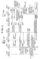
- FIG. 2 is a sequence diagram showing a processing flow from when the digital camera A100 operating in a power saving state performs proximity wireless communication with the smartphone B100 to when the digital camera A100 establishes wireless LAN communication.
- the same reference signs as in Fig. 1 are used for describing the components of each apparatus.
- the dotted arrows used in Fig. 2 express communication via NFC
- the bold arrows used in Fig. 2 express communication via a wireless LAN.
- the digital camera A100 Before the start of the sequence shown in Fig. 2 , the digital camera A100 is not performing a shooting operation or preparations for a shooting operation, and it is in a power saving state for waiting for an operation by the user. Specifically, the digital camera A100 is in a state in which only the second control unit A120 is supplied with power, and no power is supplied to the first control unit A101 or peripheral units under the control of the first control unit A101. Similarly, no power is supplied to the proximity wireless communication unit A112 or the proximity wireless communication non-volatile memory A123 included in the proximity wireless communication unit A112.
- the proximity wireless communication unit A112 and the proximity wireless communication non-volatile memory A123 can operate by generating an electromotive force from the magnetic field generated by the proximity wireless communication unit B112 included in the smartphone B100.
- the smartphone B100 is configured to be able to switch between the enabled state and the disabled state for each of the NFC function and the wireless LAN function according to a user operation.
- the NFC function is in the "enabled” state and the wireless LAN function is in the "disabled” state.
- the smartphone B100 is executing a predetermined application on the control unit B101, the application being for establishing wireless LAN connection with the digital camera A100.
- control unit B101 of the smartphone B100 provides the proximity wireless communication unit B112 with a read request for reading information existing in the proximity wireless communication non-volatile memory A123 of the digital camera A100.
- the proximity wireless communication unit B112 provides the proximity wireless communication unit A112 of the digital camera A100 with a read request (Read command).
- the proximity wireless communication unit A112 of the digital camera A100 transmits the information within the proximity wireless communication non-volatile memory A123 to the proximity wireless communication unit B112 of the smartphone B100.
- the proximity wireless communication unit A112 does not output an interruption signal at this timing.
- the proximity wireless communication unit B112 of the smartphone B100 provides the control unit B101 with the information received at step S213.
- the control unit B101 temporarily stores the information provided at step S214 into the work memory B104.
- the smartphone B100 has acquired the information from the digital camera A100 by using the proximity wireless communication unit B112.
- the information acquired in such a manner is a wireless parameter. Therefore, the read request made at step S212 serves as a request for acquiring the wireless parameter.
- the wireless parameter is information (setting information) such as an SSID required for establishing wireless LAN connection and encryption key used in wireless LAN connection.
- the wireless parameter may also include information that can identify an individual device, such as the MAC address of the digital camera A100.
- the wireless parameter may also include information of the wireless LAN channel to be used.
- the control unit B101 provides the proximity wireless communication unit B112 with a write request (Write command) for writing information into the proximity wireless communication non-volatile memory A123 of the digital camera A100.
- the information to be written is information indicating a normal completion of the acquisition of the wireless parameter (hereinafter, this information may also be referred to as "parameter acquisition completion flag", "flag”, or "completion information").
- the proximity wireless communication unit B112 provides the proximity wireless communication unit A112 of the digital camera A100 with a write request (record request) for writing information into the proximity wireless communication non-volatile memory A123.
- the proximity wireless communication unit A112 of the digital camera A100 writes the specified value (i.e., the parameter acquisition completion flag) at the specified address in the proximity wireless communication non-volatile memory A123.
- the proximity wireless communication unit A112 When the write processing to the proximity wireless communication non-volatile memory A123 is normally completed, the proximity wireless communication unit A112, at step S218, provides the second control unit A120 with an interruption signal via the interruption signal line A124.
- the proximity wireless communication unit A112 is also able to generate an interruption signal in response to the read request from the smartphone B100 (step S212), detection of a change in the magnetic field generated by the proximity wireless communication unit B112 of the smartphone B100, or the like.
- an interruption signal is generated in response to them, the following problem may occur. That is, the user may move the smartphone B100 away from the digital camera A100 before the smartphone B100 has completely received the response from the digital camera A100, and accordingly the smartphone B100 may become unable to read the necessary information.
- the smartphone B100 since the smartphone B100 has not read the information required for accessing the digital camera A100 via the wireless LAN, the smartphone B100 does not (cannot) make an attempt to access the digital camera A100. It is useless for the digital camera A100 to nevertheless activate the wireless LAN according to the interruption signal. To avoid such a situation, an interruption signal is provided at the timing of the write processing, which is the timing at which at least the smartphone B100 has completed the reading.
- the above-described interruption signals are basically not distinguished from each other. In other words, when receiving an interruption signal, the second control unit A120 can only detect the occurrence of an event of some sort, and cannot find out the cause (interruption cause) that made the interruption signal to occur.
- the interruption cause is identified by checking whether the parameter acquisition completion flag has been written or not. This will be described later.
- the interruption signal line A124 is connected to the first control unit A101 as well.
- the digital camera A100 is in the power saving state in which no power is supplied to the first control unit A101.
- the first control unit A101 cannot detect the interruption signal.
- the first control unit A101 is the same in that it can use the interruption signal only for the purpose of detecting the timing of the event.
- the proximity wireless communication unit A112 In parallel with the provision of the interruption signal (interruption notification) at step S218, the proximity wireless communication unit A112, at step S219, returns a response indicating the completion of the writing, to the proximity wireless communication unit B112 of the smartphone B100.
- the proximity wireless communication unit B112 of the smartphone B100 notifies the control unit B101 of the completion of the writing of the parameter acquisition completion flag requested at step S216.
- the smartphone B100 has written the parameter acquisition completion flag into the proximity wireless communication non-volatile memory A123 included in the digital camera A100 by using the proximity wireless communication unit B112.
- the control unit B101 of the smartphone B100 enables the connection unit B111 by using the wireless parameter acquired at step S215.
- the control unit B101 performs processing for starting wireless LAN communication.
- the connection unit B111 searches for the other party of the wireless LAN communication. Specifically, the connection unit B111 continues the search until the connection unit A111 of the digital camera A100 is started up and the SSID acquired at step S215 is detected by the wireless LAN communication.
- the second control unit A120 of the digital camera A100 starts power supply to the first control unit A101 at step S223 in response to the interruption signal received at step S218.
- the second control unit A120 also starts power supply to the proximity wireless communication unit A112 at step S224.
- the digital camera A100 was not supplying power from the inside of the digital camera A100 to the proximity wireless communication unit A112.
- the proximity wireless communication unit A112 was obtaining power required for the operation thereof by generating an electromotive force from the magnetic field generated by the proximity wireless communication unit B112 of the smartphone B100.
- the proximity wireless communication unit A112 can obtain power from the inside of the digital camera A100.
- the proximity wireless communication unit A112 according to the present embodiment starts being supplied with power from the digital camera A100 at the same timing as the power supply to the first control unit A101 is started.
- the control signal line A125 between the first control unit A101 and the proximity wireless communication unit A112 is enabled, and the proximity wireless communication unit A112 becomes able to receive a control instruction from the first control unit A101.
- the first control unit A101 becomes able to identify the interruption cause, which made the interruption signal delivered via the interruption signal line A124 to occur, by referring to the register information within the proximity wireless communication unit A112 by using the control signal line A125.
- the first control unit A101 becomes able to clear the information of the interruption cause by using the control signal line A125.
- the digital camera A100 maintains the power saving state until the smartphone B100 normally completes the processing of reading the wireless parameter stored in the proximity wireless communication non-volatile memory A123 by using NFC communication. Maintaining the power saving state for long time as described above leads to the effect of reducing unnecessary power consumption by the digital camera A100 powered by a battery.
- interruption cause is, as described above, identified by checking whether the parameter acquisition completion flag has been written or not. The following describes this point.
- the proximity wireless communication unit A112 typically can hold information of the interruption cause in the register (not shown in the drawings) within the proximity wireless communication unit A112.
- the first control unit A101 can identify the interruption cause by referring to the register information in the proximity wireless communication unit A112 after the activation.
- the smartphone B100 is moved away before power supply to the proximity wireless communication unit A112 from the digital camera A100 is started, the register information will be cleared due to the interruption of power supply.
- power supply to the proximity wireless communication unit A112 and power supply to the first control unit A101 start with substantially the same timing.
- the first control unit A101 refers to the register information (i.e., timing after the start of power supply), there is the possibility that the information in the register has already been cleared and the first control unit A101 cannot refer to the information. If this is the case, the first control unit A101 cannot identify the cause of the occurrence of the interruption signal, and cannot determine whether to activate the wireless LAN.
- the digital camera A100 is configured such that the second control unit A120 is connected to the proximity wireless communication unit A112 only via the interruption signal line A124.
- the second control unit A120 has the function of detecting the interruption signal provided from the proximity wireless communication unit A112 via the interruption signal line A124, the second control unit A120 does not have the function of checking with the proximity wireless communication unit A112 and identifying the interruption cause.
- the second control unit A120 does not have the function of clearing the interruption signal delivered via the interruption signal line A124, either. Therefore, when detecting the interruption signal delivered via the interruption signal line A124, the second control unit A120 performs only the processing for supplying power to the first control unit A101 and the proximity wireless communication unit A112.
- the first control unit A101 supplied with power checks the information of the interruption cause in the proximity wireless communication unit A112 by using the control signal line A125, and performs an operation for clearing the interruption signal delivered via the interruption signal line A124.
- the proximity wireless communication unit A112 is driven by power supplied from the smartphone B100. After that, power supply to the proximity wireless communication unit A112 is started under the control of the second control unit A120 that has detected the interruption signal. Therefore, if the smartphone B100 is moved away from the digital camera A100 before power supply to the proximity wireless communication unit A112 is started under the control of the second control unit A120, power supply for driving the proximity wireless communication unit A112 will be interrupted. As a result, the interruption signal generated by the proximity wireless communication unit A112 will be cleared, and furthermore, the information of the interruption cause held by the proximity wireless communication unit A112 will be possibly cleared.
- the smartphone B100 writes, into the proximity wireless communication non-volatile memory A123, the information (the parameter acquisition completion flag) indicating that the wireless parameter has normally been read from the proximity wireless communication non-volatile memory A123.
- the data written into the proximity wireless communication non-volatile memory A123 is maintained even when the power supply to the proximity wireless communication unit A112 is interrupted.
- the parameter acquisition completion flag can be used as a substitute for the information of the interruption cause that can be useless (i.e., can be cleared) depending on the timing.
- the digital camera A100 can determine whether the smartphone B100 is making a request for wireless LAN connection or not, and can determine whether to activate a wireless LAN.
- applications that can be installed in the smartphone B100 include, in addition to a predetermined application for establishing wireless LAN connection, an application that can rewrite the contents of the NFC tag.
- the smartphone B100 can transmit a write request to the proximity wireless communication unit A112 of the digital camera A100.
- the proximity wireless communication unit A112 provides an interruption notification to the second control unit A120 via the interruption signal line A124 (See step S218 in Fig. 2 ).
- the first control unit A101 checks the details of the flag written in the proximity wireless communication non-volatile memory A123. In other words, the first control unit A101 checks whether a predetermined value has been written at a predetermined address. By this operation, the first control unit A101 can determine whether the application that is the root cause of the interruption notification made at step S218 is an application for establishing wireless LAN connection or not.
- the first control unit A101 activates a wireless LAN only when the writing at step S217 is performed by an entity that accesses the digital camera A100 via a wireless LAN. This operation makes it possible to avoid uselessly activating a wireless LAN.
- the first control unit A101 performs activation processing.
- This activation processing includes, for example, initialization of the shooting functions of the digital camera A100, such as initialization of the operating system (OS) and initialization of peripheral devices.
- OS operating system
- the first control unit A101 Upon completion of the activation processing, the first control unit A101, at step S226, makes a read request to the proximity wireless communication non-volatile memory A123 included in the NFC tag (proximity wireless communication unit A112).
- the proximity wireless communication unit A112 acquires information having a predetermined size from a predetermined address, and returns the information to the first control unit A101.
- the communication between the first control unit A101 and the proximity wireless communication unit A112 at steps S226 and S227 is performed by using the control signal line A125.
- the first control unit A101 temporarily stores the information acquired at step S227 into the work memory A104. Then, the first control unit A101 detects the parameter acquisition completion flag from the information temporarily stored.
- the first control unit A101 Upon detection of the parameter acquisition completion flag, the first control unit A101, at step S229, activates the connection unit A111 by using the same parameter as the wireless parameter acquired by the smartphone B100.
- the wireless parameter used here may be a fixed value held in the non-volatile memory A103, or data generated at random every time in consideration of the security. In the case of random generation, the first control unit A101 holds the generated data in the proximity wireless communication non-volatile memory A123, and reads and uses the wireless parameter from the proximity wireless communication non-volatile memory A123 after the activation. Note that, although not shown in the drawings, the first control unit A101 does not activate the connection unit A111 when the parameter acquisition completion flag is not detected.
- the digital camera A100 has determined whether or not to activate the connection unit A111 according to the parameter acquisition completion flag written in the proximity wireless communication non-volatile memory A123 by the smartphone B100.
- the smartphone B100 that is searching for a wireless LAN device can detect the digital camera A100 via wireless LAN communication.
- the digital camera A100 and the smartphone B100 establish wireless LAN connection.
- the digital camera A100 and the smartphone B100 perform wireless LAN communication.
- Fig. 3A is a flowchart showing the processing performed by the second control unit A120 of the digital camera A100.
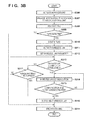
- Fig. 3B is a flowchart showing the processing performed by the first control unit A101 of the digital camera A100. Note that the processing shown in these flowcharts is realized by the first control unit A101 and the second control unit A120 of the digital camera A100, controlling each unit of the digital camera A100 according to an input signal and a program.
- the digital camera A100 is in the power saving state and no power is supplied to the first control unit A101. Therefore, the first control unit A101 is not operating, whereas the second control unit A120 is operating.
- step S301 the second control unit A120 is waiting for an interruption notification from the second operation unit A122 or the proximity wireless communication unit A112.
- the processing moves to step S302.
- the second control unit A120 determines whether the interruption notification detected at step S301 is provided by the proximity wireless communication unit A112 or not.
- the second control unit A120 is configured to have a plurality of interruption detection ports each corresponding to a different external device that can be the cause of the interruption notification, and this configuration allows for the determination at step S302.
- the processing moves to step S303, and otherwise the processing moves to step S304. It is assumed in the following that the processing has moved to step S303, and the processing performed at S304 will be described later.
- the second control unit A120 supplies power to the first control unit A101 and the proximity wireless communication unit A112 by controlling the power supply unit A121.
- the power supply unit A121 of the digital camera A100 is made up from power supply ICs that generate DC power, such as a regulator and a DC-DC converter. Therefore, the second control unit A120 can start power supply to the first control unit A101 and the proximity wireless communication unit A112 by inputting a control signal for powering on or off to the power supply ICs constituting the power supply unit A121.
- the second control unit A120 After the processing at step S303, the second control unit A120, at step S305, waits until it detects that the first control unit A101 has normally been started up. When the second control unit A120 detects the activation of the first control unit A101, the processing returns to step S301.
- the first control unit A101 of the digital camera A100 performs activation processing at step S306 in Fig. 3B .
- the first control unit A101 performs initialization of the operating system (OS), initialization of peripheral devices connected to the first control unit A101, etc.
- OS operating system
- the first control unit A101 Upon completion of the activation processing, at step S307, the first control unit A101 notifies the second control unit A120 of the completion of the activation. As a result, the second control unit A120 becomes able to detect the activation of the first control unit A101 at step S305 in Fig. 3A .
- the detection at step S305 can be realized by, for example, the second control unit A120 detecting the state of the terminal of the first control unit A101, or the second control unit A120 communicating with the first control unit A101, the detection is not necessarily performed in this way. In other words, the present embodiment can be implemented as long as it is configured such that step S305 in Fig. 3A and step S306 in Fig. 3B are brought into synchronization.
- step S304 the second control unit A120 performs a predetermined operation corresponding to the device of the second operation unit A122 that is the cause of the interruption notification.
- the predetermined operation mentioned above is an operation of some sort that corresponds to a release operation, a button operation, etc.
- the first control unit A101 reads information from the proximity wireless communication non-volatile memory A123.
- the first control unit A101 determines whether the parameter acquisition completion flag has been written in a predetermined address space of the information thus read.
- the first control unit A101 may identify the interruption cause by referring to the register information within the proximity wireless communication unit A112 in addition to detecting the parameter acquisition completion flag.
- the register information can be useless because there is the possibility that the information of the interruption cause is already cleared as described above.
- step S309 When the first control unit A101 detects the parameter acquisition completion flag at step S309, the processing moves to step S310. On the other hand, when the parameter acquisition completion flag is not detected, the processing moves to step S318 and the first control unit A101 performs end processing. Thus, the useless activation of a wireless LAN can be avoided.
- the first control unit A101 deletes the parameter acquisition completion flag from the proximity wireless communication non-volatile memory A123.
- the first control unit A101 supplies power to the connection unit A111, and activates the connection unit A111.
- the first control unit A101 sets the wireless parameter stored in the proximity wireless communication unit A112 to be an argument for the wireless LAN driver.
- This wireless parameter is the same as the parameter acquired by the smartphone B100 via NFC communication, and includes SSID required for establishing wireless LAN connection, an encryption key, etc.
- the digital camera A100 can transmit Beacon information including SSID information by using the connection unit A111.
- the first control unit A101 determines whether a wireless LAN connection with the smartphone B100 has been established or not. Since the smartphone B100 has acquired via NFC communication the same wireless parameter as the digital camera A100, it is likely that the wireless LAN connection will be normally established. However, there is the possibility that the wireless LAN connection is not established because of low remaining battery level of the smartphone B100 even though the NFC communication was successful.
- the first control unit A101 determines at step S317 whether a predetermined period has elapsed or not. When the first control unit A101 determines that the predetermined period has not elapsed, the processing returns to step S313. In the case where the wireless LAN connection is not established when the predetermined period has elapsed, the first control unit A101 determines that the smartphone B100 temporarily cannot activate a wireless LAN, and terminates the wireless LAN operation at step S316.
- the first control unit A101 starts wireless LAN communication with the smartphone B100.
- the communication mode applied to this wireless LAN communication is determined according to the operation mode of the digital camera A100 determined by the smartphone B100.
- the smartphone B100 notifies the digital camera A100 of the operation mode. For example, the following provides a description of the case where the smartphone B100 is operating in the mode of acquiring captured images within the digital camera A100.
- the first control unit A101 transfers thumbnail images stored in the recording medium A110 to the smartphone B100 via the wireless LAN.
- the smartphone B100 displays the acquired thumbnail images on the display unit B106.
- the user of the smartphone B100 selects, from among the thumbnail images displayed by the display unit B106, an image that the user wishes to download to the smartphone B100.
- the first control unit A101 via the wireless LAN, identifies the image selected on the smartphone B100, expands, on the work memory A104, the corresponding captured image acquired from the recording medium A110, and transfers the image to the smartphone B100.
- the first control unit A101 makes a determination as to whether a wireless LAN communication end notification from the smartphone B100 has been detected or not.
- the wireless LAN communication end notification mentioned above is a notification that is used for terminating the wireless LAN communication and is transmitted from the smartphone B100 when the smartphone B100 terminates the application that controls the digital camera A100.
- the processing moves to step S316.
- the first control unit A101 disconnects the wireless LAN.
- the first control unit A101 performs end processing for the first control unit A101.
- the end processing mentioned above includes end processing for the peripheral devices under the control of the first control unit A101. In other words, the end processing includes processing for putting the first control unit A101 and the peripheral devices into the state in which they can be powered off at any time.
- the interruption notification at step S218 in Fig. 2 and step S301 in Fig. 3A which is detected by the second control unit A120, occurs when the smartphone B100 completes the writing of the flag into the proximity wireless communication non-volatile memory A123.
- the interruption notification may be generated before the writing of the flag, i.e., at the timing of the receipt of the request for the writing of the flag.
- the interruption notification may be generated when the smartphone B100 makes a read request for reading the wireless parameter in the proximity wireless communication non-volatile memory A123. That is, the interruption notification may be generated at a timing different from the timing described above.
- the first control unit A101 repeats the processing at step S308 and step S309 until the parameter acquisition completion flag is detected or a timeout occurs.
- the first control unit A101 can activate the wireless LAN after detecting the parameter acquisition completion flag, regardless of the timing of the occurrence of the interruption notification.
- the proximity wireless communication unit A112 makes the interruption notification when predetermined communication is performed, and examples of the predetermined communication include the reception of the read request made at step S212 and the reception of the write request made at step S217.
- the first control unit A101 is started up later than in other cases, and accordingly the power consumption is smaller.
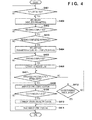
- Fig. 4 is a flowchart showing the processing performed by the control unit B101 of the smartphone B100.
- the processing shown by this flowchart is realized by the control unit B101 of the smartphone B100, controlling each unit of the smartphone B100 according to an input signal and a program.
- the smartphone B100 is executing a predetermined application on the control unit B101, the application being for establishing wireless LAN connection with the digital camera A100.
- the NFC function is in the "enabled” state
- the wireless LAN function is in the "disabled” state.
- the control unit B101 of the smartphone B100 determines whether the proximity wireless communication unit A112 has been detected or not.
- the control unit B101 detects a detection signal from the proximity wireless communication unit B112 to the proximity wireless communication unit A112. Therefore, the determination at step S401 is made by determining whether the control unit B101 has detected the detection signal or not.
- the processing moves to step S402.
- the control unit B101 performs an operation for reading information from the proximity wireless communication non-volatile memory A123 via the proximity wireless communication unit A112 of the digital camera A100.
- the information read in this stage is a wireless parameter including the SSID required for establishing wireless LAN connection, an encryption key, etc.
- the control unit B101 determines whether it has completed the reading of the wireless parameter from the proximity wireless communication non-volatile memory A123 of the digital camera A100. This determination is made based on a response from the proximity wireless communication unit A112 of the digital camera A100. The control unit B101 continues the operation for reading at step S402 until completion of the reading. Upon completion of the reading, the control unit B101 temporarily stores the information read from the proximity wireless communication non-volatile memory A123 into the work memory B104. After that, the processing moves to step S413.
- the control unit B101 determines whether the information read from the proximity wireless communication non-volatile memory A123 is normal or not. For example, a CRC code has been added to the information (data) read via NFC communication, and the control unit B101 can determine whether the read information includes a bit error or not, based on the CRC code.
- the control unit B101 determines that the information read from the proximity wireless communication non-volatile memory A123 is not normal, the processing shown in this flowchart ends. Otherwise, the processing moves to step S404.
- the control unit B101 writes the parameter acquisition completion flag into the proximity wireless communication non-volatile memory A123 of the digital camera A100 by using the proximity wireless communication unit B112.
- the proximity wireless communication unit A112 of the digital camera A100 provides the interruption notification to the second control unit A120 in response to the write request from the proximity wireless communication unit B112 (See step S301 in Fig. 3A ).
- the control unit B101 waits until the completion of the writing of the parameter acquisition completion flag. Upon completion of the writing, the control unit B101 activates a wireless LAN at step S406.
- the wireless parameter used in this stage is the wireless parameter read from the proximity wireless communication non-volatile memory A123 at step S402 and temporarily stored in the work memory B104.
- the control unit B101 determines whether wireless LAN connection with the digital camera A100 has been established or not. Since the smartphone B100 has acquired via NFC communication the same wireless parameter as the digital camera A100, it is likely that the wireless LAN connection will be normally established. However, there is the possibility that the digital camera A100 does not activate a wireless LAN, for example for the reason that during the writing of the parameter acquisition completion flag at step S404, the data has been altered and contains an error due to a communication failure. When the wireless LAN connection is not established, the control unit B101 determines at step S412 whether a predetermined period has elapsed or not. When the control unit B101 determines that the predetermined period has not elapsed, the processing returns to step S407. In the case where the wireless LAN connection is not established when the predetermined period has elapsed, the control unit B101 determines that the digital camera A100 temporarily cannot activate a wireless LAN, and terminates the wireless LAN operation at step S411.
- the control unit B101 When the wireless LAN connection is established at step S407, the control unit B101, at step S408, starts wireless LAN communication with the digital camera A100.
- the smartphone B100 notifies the digital camera A100 of the operation mode at the beginning of the wireless LAN communication performed at step S408.
- the control unit B101 may provide the digital camera A100 with information of the operation mode together with the parameter acquisition completion flag.
- the control unit B101 provides the digital camera A100 with information of the operation mode indicating "a remote shooting operation mode via a wireless LAN".
- the proximity wireless communication unit A112 of the digital camera A100 records the information indicating the operation mode (operation mode information) into the proximity wireless communication non-volatile memory A123 in addition to the parameter acquisition completion flag (See step S217 in Fig. 2 ).
- the first control unit A101 of the digital camera A100 can detect the operation mode information recorded in the proximity wireless communication non-volatile memory A123, and automatically switch to the live-view shooting mode.
- the processing by which the smartphone B100 notifies the digital camera A100 of the operation mode via the wireless LAN can be omitted.
- the control unit B101 determines whether to end the wireless LAN communication or not.
- the control unit B101 continues the wireless LAN communication at step S408 until it determines to end the wireless LAN communication.
- the control unit B101 transmits the wireless LAN communication end notification to the digital camera A100. For example, when an operation for ending the application is selected on the operation unit B105 by the user, the control unit B101 determines to end the wireless LAN communication.
- step S411 the control unit B101 disconnects the wireless LAN.
- both the digital camera A100 and the smartphone B100 can normally end the wireless LAN communication.
- connection unit A111 and the connection unit B111 perform wireless LAN communication.
- the present embodiment can be implemented even when the wireless LAN communication is replaced with the IEEE 802.15 standard (so-called Bluetooth (registered trademark)). If this is the case, the parameter exchanged in the proximity wireless communication via the proximity wireless communication unit A112 and the proximity wireless communication unit B112 is replaced with a parameter for Bluetooth (registered trademark).
- the smartphone B100 writes the parameter acquisition completion flag into the proximity wireless communication non-volatile memory A123 when the smartphone B100 can normally read the wireless parameter stored in the proximity wireless communication non-volatile memory A123 of the digital camera A100.
- the digital camera A100 recovers from the power saving state when detecting the interruption notification generated at the writing of the parameter acquisition completion flag. In other words, the digital camera A100 does not recover from the power saving state until the smartphone B100 normally completes the reading of the wireless parameter. This operation leads to the effect of reducing unnecessary power consumption by the digital camera A100 powered by a battery.
- the procedure of exchanging the wireless parameter described in the present embodiment above is achieved by short range communication represented by NFC. Therefore, the success rate of communication depends on the physical distance between devices. For this reason, the digital camera A100 also performs an operation for determining whether the parameter acquisition completion flag that is considered as having been written by the smartphone B100 has a normal value or not. When the digital camera A100 cannot detect a normal flag, the digital camera A100 can immediately switch to the power saving state without starting up a wireless LAN. In this way, by performing the processing for detecting a normal flag, the digital camera A100 can avoid unnecessarily activating a wireless LAN. That is, this operation also leads to the effect of reducing unnecessary power consumption by the digital camera A100 powered by a battery.
- the smartphone B100 writes the parameter acquisition completion flag into the proximity wireless communication non-volatile memory A123 upon acquisition of the wireless parameter from the digital camera A100 via NFC.
- the digital camera A100 recovers from the power saving state to the normal state according to the interruption notification provided in response to the writing of the parameter acquisition completion flag for example, and detects the parameter acquisition completion flag.
- the digital camera A100 can find out the cause of the recovering to the normal state, and can activate a wireless LAN only when necessary.
- the embodiment above is described based on the assumption that the interruption notification from the proximity wireless communication unit A112 cannot express the details of the event (Read or Write).
- the interruption notification from the proximity wireless communication unit A112 can also express the details of the event
- the timing of starting the power supply to the first control unit A101 may be controlled by a means other than the interruption notification from the proximity wireless communication unit A112.
- the second control unit A120 which has received the interruption notification including the details of the event may determine whether to supply power to the first control unit A101.
- the second control unit A120 does not supply power to the first control unit A101 when receiving the interruption notification indicating the Read event from the proximity wireless communication unit A112, and the second control unit A120 supplies power to the first control unit A101 when receiving the interruption notification indicating the Write event.
- the processing for determining whether or not to provide the interruption notification from the proximity wireless communication unit A112 based on whether the request from the external apparatus is Read or Write is performed in the same manner even when the state is not the power saving state.
- the proximity wireless communication unit A112 does not provide the interruption notification in the same manner, even if the first control unit A101 is being supplied with power. This operation lowers the possibility of the useless activation of a wireless LAN.
- Embodiment(s) of the present invention can also be realized by a computer of a system or apparatus that reads out and executes computer executable instructions (e.g., one or more programs) recorded on a storage medium (which may also be referred to more fully as a 'non-transitory computer-readable storage medium') to perform the functions of one or more of the above-described embodiment(s) and/or that includes one or more circuits (e.g., application specific integrated circuit (ASIC)) for performing the functions of one or more of the above-described embodiment(s), and by a method performed by the computer of the system or apparatus by, for example, reading out and executing the computer executable instructions from the storage medium to perform the functions of one or more of the above-described embodiment(s) and/or controlling the one or more circuits to perform the functions of one or more of the above-described embodiment(s).
- computer executable instructions e.g., one or more programs
- a storage medium which may also be referred to more fully as
- the computer may comprise one or more processors (e.g., central processing unit (CPU), micro processing unit (MPU)) and may include a network of separate computers or separate processors to read out and execute the computer executable instructions.
- the computer executable instructions may be provided to the computer, for example, from a network or the storage medium.
- the storage medium may include, for example, one or more of a hard disk, a random-access memory (RAM), a read only memory (ROM), a storage of distributed computing systems, an optical disk (such as a compact disc (CD), digital versatile disc (DVD), or Blu-ray Disc (BD)TM), a flash memory device, a memory card, and the like.
Landscapes
- Engineering & Computer Science (AREA)
- Computer Networks & Wireless Communication (AREA)
- Signal Processing (AREA)
- Computer Security & Cryptography (AREA)
- Studio Devices (AREA)
- Mobile Radio Communication Systems (AREA)
- Television Signal Processing For Recording (AREA)
Applications Claiming Priority (1)
| Application Number | Priority Date | Filing Date | Title |
|---|---|---|---|
| JP2014121848A JP6383187B2 (ja) | 2014-06-12 | 2014-06-12 | 通信装置、通信装置の制御方法、及びプログラム |
Publications (2)
| Publication Number | Publication Date |
|---|---|
| EP2961202A1 true EP2961202A1 (de) | 2015-12-30 |
| EP2961202B1 EP2961202B1 (de) | 2017-09-27 |
Family
ID=53496407
Family Applications (1)
| Application Number | Title | Priority Date | Filing Date |
|---|---|---|---|
| EP15171964.8A Active EP2961202B1 (de) | 2014-06-12 | 2015-06-12 | Kommunikationsvorrichtung und verfahren zur steuerung einer kommunikationsvorrichtung |
Country Status (6)
| Country | Link |
|---|---|
| US (1) | US9681384B2 (de) |
| EP (1) | EP2961202B1 (de) |
| JP (1) | JP6383187B2 (de) |
| KR (1) | KR101907415B1 (de) |
| CN (1) | CN105307103B (de) |
| RU (1) | RU2635282C2 (de) |
Cited By (1)
| Publication number | Priority date | Publication date | Assignee | Title |
|---|---|---|---|---|
| ITUA20162037A1 (it) * | 2016-03-25 | 2017-09-25 | Stefano Bertuzzi | Sistema di fruizione dati e contenuti multimediali attinenti ad oggetti dislocati in un’area |
Families Citing this family (5)
| Publication number | Priority date | Publication date | Assignee | Title |
|---|---|---|---|---|
| KR102445859B1 (ko) * | 2014-08-12 | 2022-09-20 | 소니그룹주식회사 | 정보 처리 장치, 정보 처리 방법 및 프로그램 |
| JP6463050B2 (ja) * | 2014-09-08 | 2019-01-30 | キヤノン株式会社 | 通信装置およびその制御方法ならびにプログラム |
| US10390113B2 (en) * | 2015-09-07 | 2019-08-20 | Lg Electronics Inc. | Method and apparatus for controlling device using bluetooth technology |
| JP6672780B2 (ja) * | 2015-12-22 | 2020-03-25 | ソニー株式会社 | 情報処理装置、情報処理方法、およびプログラム |
| JP7679225B2 (ja) * | 2021-04-30 | 2025-05-19 | キヤノン株式会社 | アクセサリ、電子機器、及び撮像システム |
Citations (4)
| Publication number | Priority date | Publication date | Assignee | Title |
|---|---|---|---|---|
| JP2002204239A (ja) | 2000-10-24 | 2002-07-19 | Sony Corp | 情報処理装置および方法、電子機器、情報処理システム、並びに記録媒体 |
| EP1809056A2 (de) * | 2006-01-13 | 2007-07-18 | Samsung Electronics Co., Ltd. | Dualmodusendgerät und Verfahren dafür |
| WO2013111537A1 (en) * | 2012-01-27 | 2013-08-01 | Canon Kabushiki Kaisha | Communication apparatus, communication apparatus control method, and program |
| EP2711864A1 (de) * | 2012-09-25 | 2014-03-26 | Gemalto SA | Verfahren zur Konfiguration von zwei drahtlosen Vorrichtungen |
Family Cites Families (13)
| Publication number | Priority date | Publication date | Assignee | Title |
|---|---|---|---|---|
| JP4895346B2 (ja) * | 2004-11-19 | 2012-03-14 | キヤノン株式会社 | 通信装置及びシステムならびにそれらの制御方法 |
| JP4571010B2 (ja) * | 2005-05-16 | 2010-10-27 | 富士通株式会社 | 携帯電話機を節電できるip電話システム、情報処理端末および携帯電話機 |
| JP5065876B2 (ja) * | 2007-07-31 | 2012-11-07 | 株式会社リコー | 情報処理装置、情報処理システムおよび情報処理装置で実行されるプログラム |
| US8116679B2 (en) * | 2008-09-15 | 2012-02-14 | Sony Ericsson Mobile Communications Ab | WLAN connection facilitated via near field communication |
| US20110106954A1 (en) * | 2008-09-26 | 2011-05-05 | Manjirnath Chatterjee | System and method for inductively pairing devices to share data or resources |
| JP4941496B2 (ja) * | 2009-04-03 | 2012-05-30 | カシオ計算機株式会社 | 無線通信装置及びプログラム |
| US20120238206A1 (en) | 2011-03-14 | 2012-09-20 | Research In Motion Limited | Communications device providing near field communication (nfc) secure element disabling features related methods |
| JP6012160B2 (ja) * | 2011-11-10 | 2016-10-25 | キヤノン株式会社 | 通信装置、通信装置の制御方法、撮像装置、撮像装置の制御方法、プログラム |
| EP2618497B1 (de) | 2012-01-20 | 2017-04-05 | BlackBerry Limited | Mobile drahtlose Kommunikationsvorrichtung mit NFC-Antennenabtastschalter und zugehörige Verfahren |
| JP5939819B2 (ja) * | 2012-01-31 | 2016-06-22 | キヤノン株式会社 | 通信装置、通信装置の制御方法、通信システム、プログラム |
| JP6141034B2 (ja) * | 2012-01-31 | 2017-06-07 | キヤノン株式会社 | 通信装置、通信装置の制御方法、プログラム |
| JP5924983B2 (ja) * | 2012-03-05 | 2016-05-25 | キヤノン株式会社 | 情報処理装置、その制御方法およびプログラム |
| CN104041067B (zh) * | 2012-10-10 | 2018-04-20 | 松下电器(美国)知识产权公司 | 通信装置、通信系统、移动终端、记录介质以及服务器 |
-
2014
- 2014-06-12 JP JP2014121848A patent/JP6383187B2/ja active Active
-
2015
- 2015-06-10 US US14/735,497 patent/US9681384B2/en active Active
- 2015-06-10 RU RU2015122408A patent/RU2635282C2/ru active
- 2015-06-10 CN CN201510315988.5A patent/CN105307103B/zh active Active
- 2015-06-12 EP EP15171964.8A patent/EP2961202B1/de active Active
- 2015-06-12 KR KR1020150083120A patent/KR101907415B1/ko not_active Expired - Fee Related
Patent Citations (4)
| Publication number | Priority date | Publication date | Assignee | Title |
|---|---|---|---|---|
| JP2002204239A (ja) | 2000-10-24 | 2002-07-19 | Sony Corp | 情報処理装置および方法、電子機器、情報処理システム、並びに記録媒体 |
| EP1809056A2 (de) * | 2006-01-13 | 2007-07-18 | Samsung Electronics Co., Ltd. | Dualmodusendgerät und Verfahren dafür |
| WO2013111537A1 (en) * | 2012-01-27 | 2013-08-01 | Canon Kabushiki Kaisha | Communication apparatus, communication apparatus control method, and program |
| EP2711864A1 (de) * | 2012-09-25 | 2014-03-26 | Gemalto SA | Verfahren zur Konfiguration von zwei drahtlosen Vorrichtungen |
Cited By (1)
| Publication number | Priority date | Publication date | Assignee | Title |
|---|---|---|---|---|
| ITUA20162037A1 (it) * | 2016-03-25 | 2017-09-25 | Stefano Bertuzzi | Sistema di fruizione dati e contenuti multimediali attinenti ad oggetti dislocati in un’area |
Also Published As
| Publication number | Publication date |
|---|---|
| CN105307103A (zh) | 2016-02-03 |
| RU2015122408A (ru) | 2017-01-10 |
| JP2016001856A (ja) | 2016-01-07 |
| JP6383187B2 (ja) | 2018-08-29 |
| CN105307103B (zh) | 2019-05-10 |
| RU2635282C2 (ru) | 2017-11-09 |
| US20150365899A1 (en) | 2015-12-17 |
| KR20150143350A (ko) | 2015-12-23 |
| KR101907415B1 (ko) | 2018-10-12 |
| US9681384B2 (en) | 2017-06-13 |
| EP2961202B1 (de) | 2017-09-27 |
Similar Documents
| Publication | Publication Date | Title |
|---|---|---|
| EP2961202B1 (de) | Kommunikationsvorrichtung und verfahren zur steuerung einer kommunikationsvorrichtung | |
| US9787860B2 (en) | Image forming apparatus with option for disabling near-field communication and direct wireless communication | |
| KR101791860B1 (ko) | 통신장치, 및 통신장치의 제어 방법 | |
| US9628602B2 (en) | Communication apparatus and control method therefor | |
| EP3133520B1 (de) | Kommunikationsapparat, methode zur kontrolle des apparats und programm | |
| US10541568B2 (en) | Power transmission device for wirelessly transmitting electric power to power reception device, control method for power transmission device, and recording medium | |
| US10512111B2 (en) | Electronic apparatus and control method thereof | |
| US10863074B2 (en) | Communication apparatus, control method of the same, electronic apparatus, and system | |
| JP5930778B2 (ja) | 通信装置、その制御方法、プログラム | |
| US10333783B2 (en) | Data processing apparatus, communication apparatus, and control methods for the same | |
| US9560476B2 (en) | Wireless communication apparatus capable of communicating with external apparatus, controlling method for wireless communication apparatus, and storage medium | |
| US10084952B2 (en) | Communication apparatus wirelessly communicating with external apparatus, control method of communication apparatus, and storage medium | |
| JP6767859B2 (ja) | 通信装置およびその制御方法、プログラム並びに記憶媒体 | |
| US10645269B2 (en) | Communication apparatus for wirelessly communicating with external apparatus, method, and recording medium | |
| EP3506620B1 (de) | Kommunikationsvorrichtung, verfahren zur steuerung einer kommunikationsvorrichtung und computerprogramm | |
| JP5968108B2 (ja) | 通信装置 | |
| JP2017073737A (ja) | 通信装置、通信装置の制御方法及びプログラム | |
| JP2008060845A (ja) | 画像処理装置及び画像処理方法 |
Legal Events
| Date | Code | Title | Description |
|---|---|---|---|
| PUAI | Public reference made under article 153(3) epc to a published international application that has entered the european phase |
Free format text: ORIGINAL CODE: 0009012 |
|
| AK | Designated contracting states |
Kind code of ref document: A1 Designated state(s): AL AT BE BG CH CY CZ DE DK EE ES FI FR GB GR HR HU IE IS IT LI LT LU LV MC MK MT NL NO PL PT RO RS SE SI SK SM TR |
|
| AX | Request for extension of the european patent |
Extension state: BA ME |
|
| 17P | Request for examination filed |
Effective date: 20160630 |
|
| RBV | Designated contracting states (corrected) |
Designated state(s): AL AT BE BG CH CY CZ DE DK EE ES FI FR GB GR HR HU IE IS IT LI LT LU LV MC MK MT NL NO PL PT RO RS SE SI SK SM TR |
|
| 17Q | First examination report despatched |
Effective date: 20160826 |
|
| GRAP | Despatch of communication of intention to grant a patent |
Free format text: ORIGINAL CODE: EPIDOSNIGR1 |
|
| INTG | Intention to grant announced |
Effective date: 20170403 |
|
| GRAS | Grant fee paid |
Free format text: ORIGINAL CODE: EPIDOSNIGR3 |
|
| GRAA | (expected) grant |
Free format text: ORIGINAL CODE: 0009210 |
|
| AK | Designated contracting states |
Kind code of ref document: B1 Designated state(s): AL AT BE BG CH CY CZ DE DK EE ES FI FR GB GR HR HU IE IS IT LI LT LU LV MC MK MT NL NO PL PT RO RS SE SI SK SM TR |
|
| REG | Reference to a national code |
Ref country code: GB Ref legal event code: FG4D |
|
| REG | Reference to a national code |
Ref country code: CH Ref legal event code: EP |
|
| REG | Reference to a national code |
Ref country code: AT Ref legal event code: REF Ref document number: 933037 Country of ref document: AT Kind code of ref document: T Effective date: 20171015 |
|
| REG | Reference to a national code |
Ref country code: IE Ref legal event code: FG4D |
|
| REG | Reference to a national code |
Ref country code: DE Ref legal event code: R096 Ref document number: 602015004959 Country of ref document: DE |
|
| PG25 | Lapsed in a contracting state [announced via postgrant information from national office to epo] |
Ref country code: LT Free format text: LAPSE BECAUSE OF FAILURE TO SUBMIT A TRANSLATION OF THE DESCRIPTION OR TO PAY THE FEE WITHIN THE PRESCRIBED TIME-LIMIT Effective date: 20170927 Ref country code: NO Free format text: LAPSE BECAUSE OF FAILURE TO SUBMIT A TRANSLATION OF THE DESCRIPTION OR TO PAY THE FEE WITHIN THE PRESCRIBED TIME-LIMIT Effective date: 20171227 Ref country code: HR Free format text: LAPSE BECAUSE OF FAILURE TO SUBMIT A TRANSLATION OF THE DESCRIPTION OR TO PAY THE FEE WITHIN THE PRESCRIBED TIME-LIMIT Effective date: 20170927 Ref country code: FI Free format text: LAPSE BECAUSE OF FAILURE TO SUBMIT A TRANSLATION OF THE DESCRIPTION OR TO PAY THE FEE WITHIN THE PRESCRIBED TIME-LIMIT Effective date: 20170927 Ref country code: SE Free format text: LAPSE BECAUSE OF FAILURE TO SUBMIT A TRANSLATION OF THE DESCRIPTION OR TO PAY THE FEE WITHIN THE PRESCRIBED TIME-LIMIT Effective date: 20170927 |
|
| REG | Reference to a national code |
Ref country code: NL Ref legal event code: MP Effective date: 20170927 |
|
| REG | Reference to a national code |
Ref country code: LT Ref legal event code: MG4D |
|
| REG | Reference to a national code |
Ref country code: AT Ref legal event code: MK05 Ref document number: 933037 Country of ref document: AT Kind code of ref document: T Effective date: 20170927 |
|
| PG25 | Lapsed in a contracting state [announced via postgrant information from national office to epo] |
Ref country code: RS Free format text: LAPSE BECAUSE OF FAILURE TO SUBMIT A TRANSLATION OF THE DESCRIPTION OR TO PAY THE FEE WITHIN THE PRESCRIBED TIME-LIMIT Effective date: 20170927 Ref country code: LV Free format text: LAPSE BECAUSE OF FAILURE TO SUBMIT A TRANSLATION OF THE DESCRIPTION OR TO PAY THE FEE WITHIN THE PRESCRIBED TIME-LIMIT Effective date: 20170927 Ref country code: GR Free format text: LAPSE BECAUSE OF FAILURE TO SUBMIT A TRANSLATION OF THE DESCRIPTION OR TO PAY THE FEE WITHIN THE PRESCRIBED TIME-LIMIT Effective date: 20171228 Ref country code: BG Free format text: LAPSE BECAUSE OF FAILURE TO SUBMIT A TRANSLATION OF THE DESCRIPTION OR TO PAY THE FEE WITHIN THE PRESCRIBED TIME-LIMIT Effective date: 20171227 |
|
| PG25 | Lapsed in a contracting state [announced via postgrant information from national office to epo] |
Ref country code: NL Free format text: LAPSE BECAUSE OF FAILURE TO SUBMIT A TRANSLATION OF THE DESCRIPTION OR TO PAY THE FEE WITHIN THE PRESCRIBED TIME-LIMIT Effective date: 20170927 |
|
| PG25 | Lapsed in a contracting state [announced via postgrant information from national office to epo] |
Ref country code: CZ Free format text: LAPSE BECAUSE OF FAILURE TO SUBMIT A TRANSLATION OF THE DESCRIPTION OR TO PAY THE FEE WITHIN THE PRESCRIBED TIME-LIMIT Effective date: 20170927 Ref country code: RO Free format text: LAPSE BECAUSE OF FAILURE TO SUBMIT A TRANSLATION OF THE DESCRIPTION OR TO PAY THE FEE WITHIN THE PRESCRIBED TIME-LIMIT Effective date: 20170927 Ref country code: ES Free format text: LAPSE BECAUSE OF FAILURE TO SUBMIT A TRANSLATION OF THE DESCRIPTION OR TO PAY THE FEE WITHIN THE PRESCRIBED TIME-LIMIT Effective date: 20170927 |
|
| PG25 | Lapsed in a contracting state [announced via postgrant information from national office to epo] |
Ref country code: EE Free format text: LAPSE BECAUSE OF FAILURE TO SUBMIT A TRANSLATION OF THE DESCRIPTION OR TO PAY THE FEE WITHIN THE PRESCRIBED TIME-LIMIT Effective date: 20170927 Ref country code: IS Free format text: LAPSE BECAUSE OF FAILURE TO SUBMIT A TRANSLATION OF THE DESCRIPTION OR TO PAY THE FEE WITHIN THE PRESCRIBED TIME-LIMIT Effective date: 20180127 Ref country code: AT Free format text: LAPSE BECAUSE OF FAILURE TO SUBMIT A TRANSLATION OF THE DESCRIPTION OR TO PAY THE FEE WITHIN THE PRESCRIBED TIME-LIMIT Effective date: 20170927 Ref country code: IT Free format text: LAPSE BECAUSE OF FAILURE TO SUBMIT A TRANSLATION OF THE DESCRIPTION OR TO PAY THE FEE WITHIN THE PRESCRIBED TIME-LIMIT Effective date: 20170927 Ref country code: SK Free format text: LAPSE BECAUSE OF FAILURE TO SUBMIT A TRANSLATION OF THE DESCRIPTION OR TO PAY THE FEE WITHIN THE PRESCRIBED TIME-LIMIT Effective date: 20170927 Ref country code: SM Free format text: LAPSE BECAUSE OF FAILURE TO SUBMIT A TRANSLATION OF THE DESCRIPTION OR TO PAY THE FEE WITHIN THE PRESCRIBED TIME-LIMIT Effective date: 20170927 |
|
| REG | Reference to a national code |
Ref country code: DE Ref legal event code: R097 Ref document number: 602015004959 Country of ref document: DE |
|
| PG25 | Lapsed in a contracting state [announced via postgrant information from national office to epo] |
Ref country code: DK Free format text: LAPSE BECAUSE OF FAILURE TO SUBMIT A TRANSLATION OF THE DESCRIPTION OR TO PAY THE FEE WITHIN THE PRESCRIBED TIME-LIMIT Effective date: 20170927 |
|
| PLBE | No opposition filed within time limit |
Free format text: ORIGINAL CODE: 0009261 |
|
| STAA | Information on the status of an ep patent application or granted ep patent |
Free format text: STATUS: NO OPPOSITION FILED WITHIN TIME LIMIT |
|
| PG25 | Lapsed in a contracting state [announced via postgrant information from national office to epo] |
Ref country code: PL Free format text: LAPSE BECAUSE OF FAILURE TO SUBMIT A TRANSLATION OF THE DESCRIPTION OR TO PAY THE FEE WITHIN THE PRESCRIBED TIME-LIMIT Effective date: 20170927 |
|
| 26N | No opposition filed |
Effective date: 20180628 |
|
| PG25 | Lapsed in a contracting state [announced via postgrant information from national office to epo] |
Ref country code: SI Free format text: LAPSE BECAUSE OF FAILURE TO SUBMIT A TRANSLATION OF THE DESCRIPTION OR TO PAY THE FEE WITHIN THE PRESCRIBED TIME-LIMIT Effective date: 20170927 |
|
| REG | Reference to a national code |
Ref country code: CH Ref legal event code: PL |
|
| REG | Reference to a national code |
Ref country code: BE Ref legal event code: MM Effective date: 20180630 |
|
| REG | Reference to a national code |
Ref country code: IE Ref legal event code: MM4A |
|
| PG25 | Lapsed in a contracting state [announced via postgrant information from national office to epo] |
Ref country code: LU Free format text: LAPSE BECAUSE OF NON-PAYMENT OF DUE FEES Effective date: 20180612 Ref country code: MC Free format text: LAPSE BECAUSE OF FAILURE TO SUBMIT A TRANSLATION OF THE DESCRIPTION OR TO PAY THE FEE WITHIN THE PRESCRIBED TIME-LIMIT Effective date: 20170927 |
|
| PG25 | Lapsed in a contracting state [announced via postgrant information from national office to epo] |
Ref country code: IE Free format text: LAPSE BECAUSE OF NON-PAYMENT OF DUE FEES Effective date: 20180612 Ref country code: FR Free format text: LAPSE BECAUSE OF NON-PAYMENT OF DUE FEES Effective date: 20180630 Ref country code: LI Free format text: LAPSE BECAUSE OF NON-PAYMENT OF DUE FEES Effective date: 20180630 Ref country code: CH Free format text: LAPSE BECAUSE OF NON-PAYMENT OF DUE FEES Effective date: 20180630 |
|
| PG25 | Lapsed in a contracting state [announced via postgrant information from national office to epo] |
Ref country code: BE Free format text: LAPSE BECAUSE OF NON-PAYMENT OF DUE FEES Effective date: 20180630 |
|
| PG25 | Lapsed in a contracting state [announced via postgrant information from national office to epo] |
Ref country code: MT Free format text: LAPSE BECAUSE OF NON-PAYMENT OF DUE FEES Effective date: 20180612 |
|
| PG25 | Lapsed in a contracting state [announced via postgrant information from national office to epo] |
Ref country code: TR Free format text: LAPSE BECAUSE OF FAILURE TO SUBMIT A TRANSLATION OF THE DESCRIPTION OR TO PAY THE FEE WITHIN THE PRESCRIBED TIME-LIMIT Effective date: 20170927 |
|
| PG25 | Lapsed in a contracting state [announced via postgrant information from national office to epo] |
Ref country code: PT Free format text: LAPSE BECAUSE OF FAILURE TO SUBMIT A TRANSLATION OF THE DESCRIPTION OR TO PAY THE FEE WITHIN THE PRESCRIBED TIME-LIMIT Effective date: 20170927 |
|
| PG25 | Lapsed in a contracting state [announced via postgrant information from national office to epo] |
Ref country code: CY Free format text: LAPSE BECAUSE OF FAILURE TO SUBMIT A TRANSLATION OF THE DESCRIPTION OR TO PAY THE FEE WITHIN THE PRESCRIBED TIME-LIMIT Effective date: 20170927 Ref country code: MK Free format text: LAPSE BECAUSE OF NON-PAYMENT OF DUE FEES Effective date: 20170927 Ref country code: HU Free format text: LAPSE BECAUSE OF FAILURE TO SUBMIT A TRANSLATION OF THE DESCRIPTION OR TO PAY THE FEE WITHIN THE PRESCRIBED TIME-LIMIT; INVALID AB INITIO Effective date: 20150612 |
|
| PG25 | Lapsed in a contracting state [announced via postgrant information from national office to epo] |
Ref country code: AL Free format text: LAPSE BECAUSE OF FAILURE TO SUBMIT A TRANSLATION OF THE DESCRIPTION OR TO PAY THE FEE WITHIN THE PRESCRIBED TIME-LIMIT Effective date: 20170927 |
|
| PGFP | Annual fee paid to national office [announced via postgrant information from national office to epo] |
Ref country code: DE Payment date: 20250520 Year of fee payment: 11 |
|
| PGFP | Annual fee paid to national office [announced via postgrant information from national office to epo] |
Ref country code: GB Payment date: 20250520 Year of fee payment: 11 |