EP2960581A1 - Positioniereinrichtung, kochmulde und herd - Google Patents
Positioniereinrichtung, kochmulde und herd Download PDFInfo
- Publication number
- EP2960581A1 EP2960581A1 EP15169758.8A EP15169758A EP2960581A1 EP 2960581 A1 EP2960581 A1 EP 2960581A1 EP 15169758 A EP15169758 A EP 15169758A EP 2960581 A1 EP2960581 A1 EP 2960581A1
- Authority
- EP
- European Patent Office
- Prior art keywords
- positioning device
- engagement
- positioning
- cooktop
- opening
- Prior art date
- Legal status (The legal status is an assumption and is not a legal conclusion. Google has not performed a legal analysis and makes no representation as to the accuracy of the status listed.)
- Granted
Links
- 238000010411 cooking Methods 0.000 title claims 2
- 239000000463 material Substances 0.000 claims abstract description 11
- 239000004033 plastic Substances 0.000 claims abstract description 10
- 238000003780 insertion Methods 0.000 claims description 6
- 230000037431 insertion Effects 0.000 claims description 6
- 244000144980 herd Species 0.000 description 3
- 238000004519 manufacturing process Methods 0.000 description 3
- 238000001746 injection moulding Methods 0.000 description 2
- 238000003825 pressing Methods 0.000 description 2
- 229910000838 Al alloy Inorganic materials 0.000 description 1
- 239000004696 Poly ether ether ketone Substances 0.000 description 1
- 238000007792 addition Methods 0.000 description 1
- 230000001419 dependent effect Effects 0.000 description 1
- 239000003365 glass fiber Substances 0.000 description 1
- 238000002347 injection Methods 0.000 description 1
- 239000007924 injection Substances 0.000 description 1
- 239000007769 metal material Substances 0.000 description 1
- 229920002530 polyetherether ketone Polymers 0.000 description 1
Images


Classifications
-
- F—MECHANICAL ENGINEERING; LIGHTING; HEATING; WEAPONS; BLASTING
- F23—COMBUSTION APPARATUS; COMBUSTION PROCESSES
- F23C—METHODS OR APPARATUS FOR COMBUSTION USING FLUID FUEL OR SOLID FUEL SUSPENDED IN A CARRIER GAS OR AIR
- F23C5/00—Disposition of burners with respect to the combustion chamber or to one another; Mounting of burners in combustion apparatus
-
- F—MECHANICAL ENGINEERING; LIGHTING; HEATING; WEAPONS; BLASTING
- F24—HEATING; RANGES; VENTILATING
- F24C—DOMESTIC STOVES OR RANGES ; DETAILS OF DOMESTIC STOVES OR RANGES, OF GENERAL APPLICATION
- F24C3/00—Stoves or ranges for gaseous fuels
- F24C3/08—Arrangement or mounting of burners
- F24C3/085—Arrangement or mounting of burners on ranges
-
- F—MECHANICAL ENGINEERING; LIGHTING; HEATING; WEAPONS; BLASTING
- F23—COMBUSTION APPARATUS; COMBUSTION PROCESSES
- F23C—METHODS OR APPARATUS FOR COMBUSTION USING FLUID FUEL OR SOLID FUEL SUSPENDED IN A CARRIER GAS OR AIR
- F23C5/00—Disposition of burners with respect to the combustion chamber or to one another; Mounting of burners in combustion apparatus
- F23C5/02—Structural details of mounting
-
- F—MECHANICAL ENGINEERING; LIGHTING; HEATING; WEAPONS; BLASTING
- F24—HEATING; RANGES; VENTILATING
- F24C—DOMESTIC STOVES OR RANGES ; DETAILS OF DOMESTIC STOVES OR RANGES, OF GENERAL APPLICATION
- F24C3/00—Stoves or ranges for gaseous fuels
- F24C3/08—Arrangement or mounting of burners
- F24C3/082—Arrangement or mounting of burners on stoves
Definitions
- the present invention relates to a positioning device, a cooktop and a stove.
- the gas burners are positioned relative to provided in the cover plate cutouts before placing a cover plate or a top sheet of the gas hob. This can be done, for example, with the help of a bottom trough of the gas hob of screwed positioning. It is therefore desirable to simplify the assembly of the gas burners.
- an object of the present invention is to provide an improved positioning device.
- a positioning device for positioning a gas burner in or on a cooktop with at least one engagement portion, which is adapted to engage positively in a breakthrough of a bottom trough of the cooktop proposed.
- the positioning device is made of a plastic material.
- the positioning device is adapted to intervene in a form-fitting manner in the opening of the floor pan, it can be attached without additional aids such as screws to the floor pan.
- the manufacture of the positioning device from a plastic material enables its cost-effective production in large numbers, e.g. in a plastic injection molding process.
- the positioning device is made of a heat-resistant plastic material such as polyetheretherketone.
- the positioning device can be made of a fiber-reinforced, in particular glass fiber reinforced, plastic material.
- the positioning device has at least one retaining pin, which is adapted to engage positively in a burner housing of the gas burner.
- the burner housing receiving portions are preferably provided, in which engages the retaining pin.
- the positioning means on two spaced-apart retaining pins.
- the positioning device has a base section, on which the at least one engagement section and the at least one retaining pin are arranged.
- the base portion is preferably strip-shaped.
- the at least one engagement portion and the at least one retaining pin are preferably positioned on opposite surfaces of the strip-shaped base portion.
- the base portion, the at least one engagement portion and the at least one retaining pin are integrally formed material.
- the positioning device can be produced in a plastic injection molding process.
- the engagement portion has at least one elastically deformable engagement arm.
- the engagement section preferably has two elastically deformable engagement arms arranged opposite one another.
- the engagement arms are preferably designed as elastically deformable snap hooks.
- an insertion bevel is provided on the at least one engagement arm for insertion of the at least one engagement arm into the opening.
- the engagement arm slides with the insertion bevel into the opening, whereby the engagement arm is resiliently deformed.
- the engagement arm snaps the breakthrough and thus fixes the positioning device on the floor pan.
- the positioning device has at least one actuating pin, which is adapted to deform the at least one engagement arm so that it engages behind the opening.
- the actuating pin is preferably insertable into the at least one engagement portion to deform the at least one engagement arm.
- the positioning device has at least one spring device which is set up to bias the positioning device against the cooktop trough.
- the spring device may be formed integral with the engagement portion material.
- the spring device is preferably a leaf spring.
- a cooktop is proposed with at least one such positioning.
- the cooktop comprises in particular a plurality of gas burners or a lower part of each gas burner and a co-operating with each gas burner lower part positioning.
- the hob is preferably a gas hob.
- the hob can be part of a household appliance. In particular, the hob is part of a stove.
- the stove is preferably a household appliance.
- the stove is a gas stove.
- the cooktop and / or the hearth also include combinations of features or embodiments described above or below with respect to the exemplary embodiments which are not explicitly mentioned.
- the person skilled in the art will also consider individual aspects as improvements or add additions to the respective basic shape of the positioning, the hob and / or the stove.
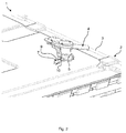
- the Fig. 1 and 2 each show a schematic perspective view of a hearth 1.
- the stove 1 is in particular a gas stove.
- the stove 1 comprises a cooktop 2, in particular a gas cooktop.
- the hob 2 has a bottom pan 3.
- the floor pan 3 is in particular a trough-shaped floor panel.
- more gas burner 4 are arranged.
- the gas burner 4 has a burner housing 5.
- the bottom tray 3 has a plurality of openings 6, of which in the Fig. 1 only two are provided with a reference numeral.
- the hob 2 further comprises a cover plate or a so-called top sheet.
- the gas burner 4 is at least partially disposed between the bottom pan 3 and the cover plate.
- the gas burner 4 projects beyond the cover plate.
- a corresponding breakthrough is provided on the cover plate.
- the burner housing 5 may be screwed to the cover plate.
- the positioning device 7 is adapted to fix the gas burner 4 for mounting the same in a predetermined position.
- the positioning device 7 is adapted to position the gas burner 4 relative to the breakthrough provided in the cover plate. After mounting the burner housing 5 on the cover plate, the positioning 7 no longer has a supporting function.
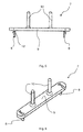
- the Fig. 3 shows a schematic side view of an embodiment of the positioning 7.
- the Fig. 4 shows a schematic perspective view of the positioning 7.
- the positioning device 7 has at least one engagement portion 8, which is adapted to engage in one of the openings 6 of the bottom trough 3 of the cooktop 2.
- the positioning device 7 preferably has two engagement sections 8.
- the number of engagement sections 8 is arbitrary.
- the positioning device 7 is made of a plastic material.
- the positioning device 7 is a plastic injection molded component.
- the positioning device 7 on a strip-shaped base portion 9, from which the engagement portions 8 extend below the underside.
- the positioning device 7 On a side facing away from the engagement portions 8 of the base portion 9 at least one retaining pin 10 is provided, which is adapted to engage the burner housing 5 of the gas burner 4 in a form-fitting manner.
- the positioning device 7 has two holding pins 10 arranged at a distance from one another.
- corresponding receiving portions 11 are provided for receiving the retaining pins 10 ( Fig. 1 ).
- the base portion 9, the retaining pins 10 and the engagement portions 8 are formed centrein Glag. The retaining pins 10 engage in the receiving portions 11 of the burner housing 5 so that the burner housing 5 can not tilt relative to the bottom pan 3.
- Each engagement section 8 preferably has at least one elastically deformable engagement arm 12, 13.
- the engagement portion 8 for example, two oppositely arranged elastically deformable engagement arms 12, 13.
- the engagement arms 12, 13 are wedge-shaped.
- the engagement arms 12, 13 are designed as snap hooks.
- an insertion bevel 14 is provided on the engagement arms 12, 13 for this purpose.
- a spring means 15 may be provided on each engaging portion 8, which is preferably formed integrally with the engaging portion 8 material.
- the spring device 15 is formed for example as a leaf spring. The spring device 15 biases the positioning device 7 against the bottom pan 3. As a result, slipping or wobbling of the positioning device 7 is prevented.
- the Fig. 5 shows a schematic side view of another embodiment of a positioning 7.
- the Fig. 6 shows the positioning device 7 in a schematic perspective view.
- the embodiment of the positioning device 7 according to the FIGS. 5 and 6 differs from the embodiment of the Positioning device according to the 3 and 4 in that each engagement section 8 has only one resiliently deformable engagement arm 12.
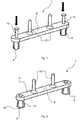
- FIGS. 7 and 8 each show in a schematic perspective view of another embodiment of a positioning device 7.
- the positioning device 7 according to the FIGS. 7 and 8 differs from the previously described embodiments of the positioning device 7 in that it comprises at least one actuating pin 16 which is adapted to deform the at least one engagement portion 8 so that it engages behind the opening 6.
- each engaging portion 8 has three or four engaging arms 12, 13, of which in the Fig. 8 only two are provided with a reference numeral.
- the engagement arms 12, 13 preferably have no insertion bevels, but are deformed by pressing the actuating pin 16 such that they engage behind the opening 6.
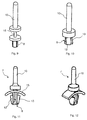
- FIGS. 9 and 10 each show in a schematic perspective view of another embodiment of a positioning device 7.
- the positioning device 7 according to the FIGS. 9 and 10 differs from the positioning device 7 according to the FIGS. 7 and 8 in that the positioning device 7 has no base section 9.
- an actuating pin 16 is provided on the underside, which is adapted to deform the engagement arms 12, 13 during depression of the retaining pin 10 so that they engage behind the opening 6 of the bottom pan 3.
- the Fig. 11 shows a schematic side view of another embodiment of a positioning device 7th Die
- Fig. 12 shows the positioning device 7 in a schematic perspective view.
- the positioning device according to the FIGS. 11 and 12 differs from the positioning device 7 according to the Fig. 1 and 2 merely in that the positioning device 7 has no base section 9.
- the positioning device 7 may be made at least partially of a metal material, such as an aluminum alloy.
- the Positioning device 7 can be found except in cooktops or herds in any home appliances application.
- the positioning device 7 can be designed in several parts.
Landscapes
- Engineering & Computer Science (AREA)
- Chemical & Material Sciences (AREA)
- Combustion & Propulsion (AREA)
- Mechanical Engineering (AREA)
- General Engineering & Computer Science (AREA)
- Combinations Of Kitchen Furniture (AREA)
- Baking, Grill, Roasting (AREA)
- Clamps And Clips (AREA)
Abstract
Description
- Die vorliegende Erfindung betrifft eine Positioniereinrichtung, eine Kochmulde und einen Herd.
- Bei der Montage eines Gasherds bzw. einer Gaskochmulde werden vor dem Auflegen einer Deckplatte bzw. eines Top Sheets der Gaskochmulde die Gasbrenner relativ zu in der Deckplatte vorgesehenen Ausschnitten positioniert. Dies kann beispielsweise mit Hilfe mit einer Bodenwanne der Gaskochmulde verschraubter Positioniereinrichtungen geschehen. Es ist daher wünschenswert, die Montage der Gasbrenner zu vereinfachen.
- Vor diesem Hintergrund besteht eine Aufgabe der vorliegenden Erfindung darin, eine verbesserte Positioniereinrichtung zur Verfügung zu stellen.
- Demgemäß wird eine Positioniereinrichtung zum Positionieren eines Gasbrenners in oder an einer Kochmulde mit mindestens einem Eingriffsabschnitt, der dazu eingerichtet ist, in einen Durchbruch einer Bodenwanne der Kochmulde formschlüssig einzugreifen, vorgeschlagen. Dabei ist die Positioniereinrichtung aus einem Kunststoffmaterial gefertigt.
- Dadurch, dass die Positioniereinrichtung dazu eingerichtet ist, in den Durchbruch der Bodenwanne formschlüssig einzugreifen, kann diese ohne zusätzliche Hilfsmittel wie beispielsweise Schrauben an der Bodenwanne befestigt werden. Die Fertigung der Positioniereinrichtung aus einem Kunststoffmaterial ermöglicht dessen kostengünstige Herstellung in großen Stückzahlen, z.B. in einem Kunststoffspritzgussverfahren. Beispielsweise ist die Positioniereinrichtung aus einem hitzebeständigen Kunststoffmaterial wie beispielsweise Polyetheretherketon gefertigt. Die Positioniereinrichtung kann aus einem faserverstärkten, insbesondere glasfaserverstärkten, Kunststoffmaterial gefertigt sein.
- Gemäß einer Ausführungsform weist die Positioniereinrichtung mindestens einen Haltestift auf, der dazu eingerichtet ist, in ein Brennergehäuse des Gasbrenners formschlüssig einzugreifen.
- An dem Brennergehäuse sind vorzugsweise Aufnahmeabschnitte vorgesehen, in die der Haltestift eingreift. Vorzugsweise weist die Positioniereinrichtung zwei voneinander beabstandet angeordnete Haltestifte auf.
- Gemäß einer weiteren Ausführungsform weist die Positioniereinrichtung einen Basisabschnitt auf, an dem der mindestens eine Eingriffsabschnitt und der mindestens eine Haltestift angeordnet sind.
- Der Basisabschnitt ist vorzugsweise leistenförmig. Der mindestens eine Eingriffsabschnitt und der mindestens eine Haltestift sind vorzugsweise an einander gegenüberliegenden Oberflächen des leistenförmigen Basisabschnitts positioniert.
- Gemäß einer weiteren Ausführungsform sind der Basisabschnitt, der mindestens eine Eingriffsabschnitt und der mindestens eine Haltestift materialeinstückig ausgebildet.
- Dies ermöglicht eine einfache und kostengünstige Herstellung der Positioniereinrichtung. Beispielsweise ist die Positioniereinrichtung in einem Kunststoffspritzgussverfahren herstellbar.
- Gemäß einer weiteren Ausführungsform weist der Eingriffsabschnitt zumindest einen elastisch verformbaren Eingriffsarm auf.
- Vorzugsweise weist der Eingriffsabschnitt zwei einander gegenüberliegend angeordnete elastisch verformbare Eingriffsarme auf. Die Eingriffsarme sind vorzugsweise als federelastisch verformbare Schnapphaken ausgebildet.
- Gemäß einer weiteren Ausführungsform ist an dem zumindest einen Eingriffsarm eine Einführschräge zum Einführen des zumindest einen Eingriffsarm in den Durchbruch vorgesehen.
- Insbesondere gleitet der Eingriffsarm beim Eindrücken des Eingriffsabschnitts in den Durchbruch der Bodenwanne mit der Einführschräge in den Durchbruch, wobei der Eingriffsarm federelastisch verformt wird. Der Eingriffsarm hinterschnappt den Durchbruch und fixiert so die Positioniereinrichtung an der Bodenwanne.
- Gemäß einer weiteren Ausführungsform weist die Positioniereinrichtung zumindest einen Betätigungsstift auf, der dazu eingerichtet ist, den zumindest einen Eingriffsarm so zu verformen, dass dieser den Durchbruch hintergreift.
- Der Betätigungsstift ist vorzugsweise in den zumindest einen Eingriffsabschnitt einführbar, um den zumindest einen Eingriffsarm zu verformen.
- Gemäß einer weiteren Ausführungsform weist die Positioniereinrichtung zumindest eine Federeinrichtung auf, die dazu eingerichtet ist, die Positioniereinrichtung gegen die Kochmuldenwanne vorzuspannen.
- Die Federeinrichtung kann materialeinstückig mit dem Eingriffsabschnitt ausgebildet sein. Die Federeinrichtung ist vorzugsweise eine Blattfeder.
- Weiterhin wird eine Kochmulde mit zumindest einer derartigen Positioniereinrichtung vorgeschlagen.
- Die Kochmulde umfasst insbesondere mehrere Gasbrenner bzw. ein Unterteil jedes Gasbrenners und eine mit jedem Gasbrennerunterteil zusammenwirkende Positioniereinrichtung. Die Kochmulde ist vorzugsweise eine Gaskochmulde. Die Kochmulde kann Teil eines Haushaltsgeräts sein. Insbesondere ist die Kochmulde Teil eines Herds.
- Weiterhin wird ein Herd mit zumindest einer derartigen Positioniereinrichtung und/oder einer derartigen Kochmulde vorgeschlagen.
- Der Herd ist vorzugsweise ein Haushaltsgerät. Insbesondere ist der Herd ein Gasherd.
- Weitere mögliche Implementierungen der Positioniereinrichtung, der Kochmulde und/oder des Herds umfassen auch nicht explizit genannte Kombinationen von zuvor oder im Folgenden bezüglich der Ausführungsbeispiele beschriebenen Merkmale oder Ausführungsformen. Dabei wird der Fachmann auch Einzelaspekte als Verbesserungen oder Ergänzungen zu der jeweiligen Grundform der Positioniereinrichtung, der Kochmulde und/oder des Herds hinzufügen.
- Weitere vorteilhafte Ausgestaltungen und Aspekte der Erfindung sind Gegenstand der Unteransprüche sowie der im Folgenden beschriebenen Ausführungsbeispiele der Positioniereinrichtung, der Kochmulde und/oder des Herds. Im Weiteren werden die Positioniereinrichtung, die Kochmulde und/oder der Herd anhand von bevorzugten Ausführungsformen unter Bezugnahme auf die beigelegten Figuren näher erläutert.
- Fig. 1
- zeigt eine schematische perspektivische Ansicht einer Ausführungsform eines Herds;
- Fig. 2
- zeigt eine weitere schematische perspektivische Ansicht des Herds gemäß der
Fig. 1 ; - Fig. 3
- zeigt eine schematische Seitenansicht einer Ausführungsform einer Positioniereinrichtung;
- Fig. 4
- zeigt eine schematische perspektivische Ansicht der Positioniereinrichtung gemäß der
Fig. 3 ; - Fig. 5
- zeigt eine schematische Seitenansicht einer weiteren Ausführungsform einer Positioniereinrichtung;
- Fig. 6
- zeigt eine schematische perspektivische Ansicht der Positioniereinrichtung gemäß der
Fig. 5 ; - Fig. 7
- zeigt eine schematische perspektivische Ansicht einer weiteren Ausführungsform einer Positioniereinrichtung;
- Fig. 8
- zeigt eine weitere schematische perspektivische Ansicht der Positioniereinrichtung gemäß der
Fig. 7 ; - Fig. 9
- zeigt eine schematische perspektivische Ansicht einer weiteren Ausführungsform einer Positioniereinrichtung;
- Fig. 10
- zeigt eine weitere schematische perspektivische Ansicht der Positioniereinrichtung gemäß der
Fig. 9 ; - Fig. 11
- zeigt eine schematische Seitenansicht einer weiteren Ausführungsform einer Positioniereinrichtung; und
- Fig. 12
- zeigt eine schematische perspektivische Ansicht der Positioniereinrichtung gemäß der
Fig. 11 . - In den Figuren sind gleiche oder funktionsgleiche Elemente mit denselben Bezugszeichen versehen worden, sofern nichts anderes angegeben ist.
- Die
Fig. 1 und2 zeigen jeweils eine schematische perspektivische Ansicht eines Herds 1. Der Herd 1 ist insbesondere ein Gasherd. Der Herd 1 umfasst eine Kochmulde 2, insbesondere eine Gaskochmulde. Die Kochmulde 2 weist eine Bodenwanne 3 auf. Die Bodenwanne 3 ist insbesondere ein wannenförmiges Bodenblech. In oder an der Bodenwanne 3 sind mehrere Gasbrenner 4 angeordnet. In denFig. 1 und2 ist jeweils lediglich ein Gasbrenner 4 gezeigt. Der Gasbrenner 4 weist ein Brennergehäuse 5 auf. Die Bodenwanne 3 weist mehrere Durchbrüche 6 auf, von denen in derFig. 1 lediglich zwei mit einem Bezugszeichen versehen sind. - Die Kochmulde 2 umfasst weiterhin eine Deckplatte oder ein sogenanntes Top Sheet. Der Gasbrenner 4 ist zumindest teilweise zwischen der Bodenwanne 3 und der Deckplatte angeordnet. Insbesondere ragt der Gasbrenner 4 über die Deckplatte hinaus. Hierzu ist an der Deckplatte ein entsprechender Durchbruch vorgesehen. Das Brennergehäuse 5 kann mit der Deckplatte verschraubt sein. Weiterhin ist in den
Fig. 1 und2 eine Positioniereinrichtung 7 zum Positionieren des Gasbrenners 4 in oder an der Kochmulde 2 gezeigt. Die Positioniereinrichtung 7 ist dazu eingerichtet den Gasbrenner 4 zum Montieren desselben in einer vorbestimmten Position zu fixieren. Beispielsweise ist die Positioniereinrichtung 7 dazu eingerichtet, den Gasbrenner 4 relativ zu dem in der Deckplatte vorgesehenen Durchbruch zu positionieren. Nach dem Montieren des Brennergehäuses 5 an der Deckplatte hat die Positioniereinrichtung 7 keine tragende Funktion mehr. - Die
Fig. 3 zeigt in einer schematischen Seitenansicht eine Ausführungsform der Positioniereinrichtung 7. DieFig. 4 zeigt eine schematische perspektivische Ansicht der Positioniereinrichtung 7. Die Positioniereinrichtung 7 weist mindestens einen Eingriffsabschnitt 8 auf, der dazu eingerichtet ist, in einen der Durchbrüche 6 der Bodenwanne 3 der Kochmulde 2 einzugreifen. Vorzugsweise weist die Positioniereinrichtung 7 zwei Eingriffsabschnitte 8 auf. Die Anzahl der Eingriffsabschnitte 8 ist beliebig. Die Positioniereinrichtung 7 ist aus einem Kunststoffmaterial gefertigt. Beispielsweise ist die Positioniereinrichtung 7 ein Kunststoffspritzgussbauteil. Wie dieFig. 1 bis 4 zeigen, weist die Positioniereinrichtung 7 einen leistenförmigen Basisabschnitt 9 auf, aus dem sich unterseitig die Eingriffsabschnitte 8 herauserstrecken. - Auf einer den Eingriffsabschnitten 8 abgewandten Seite des Basisabschnitts 9 ist zumindest ein Haltestift 10 vorgesehen, der dazu eingerichtet ist, in das Brennergehäuse 5 des Gasbrenners 4 formschlüssig einzugreifen. Beispielsweise weist die Positioniereinrichtung 7 zwei voneinander beabstandet angeordnete Haltestifte 10 auf. An dem Brennergehäuse 5 sind korrespondierende Aufnahmeabschnitte 11 zum Aufnehmen der Haltestifte 10 vorgesehen (
Fig. 1 ). Der Basisabschnitt 9, die Haltestifte 10 und die Eingriffsabschnitte 8 sind materialeinstückig ausgebildet. Die Haltestifte 10 greifen so in die Aufnahmeabschnitte 11 des Brennergehäuses 5 ein, dass das Brennergehäuse 5 relativ zu der Bodenwanne 3 nicht verkippen kann. - Jeder Eingriffsabschnitt 8 weist vorzugsweise zumindest einen elastisch verformbaren Eingriffsarm 12, 13 auf. Wie die
Fig. 3 und 4 zeigen, weist der Eingriffsabschnitt 8 beispielsweise zwei einander gegenüberliegend angeordnete elastisch verformbare Eingriffsarme 12, 13 auf. Die Eingriffsarme 12, 13 sind keilförmig ausgebildet. Insbesondere sind die Eingriffsarme 12, 13 als Schnapphaken ausgebildet. Beim Eindrücken des Eingriffsabschnitts 8 in den Durchbruch 6 der Bodenwanne 3 werden die Eingriffsarme 12, 13 elastisch verformt und schnappen hinter dem Durchbruch 6 ein. Insbesondere ist hierzu an den Eingriffsarmen 12, 13 jeweils eine Einführschräge 14 vorgesehen. - Wie die
Fig. 1 weiterhin zeigt, kann an jedem Eingriffsabschnitt 8 eine Federeinrichtung 15 vorgesehen sein, die vorzugsweise materialeinstückig mit dem Eingriffsabschnitt 8 ausgebildet ist. Die Federeinrichtung 15 ist beispielsweise als Blattfeder ausgebildet. Die Federeinrichtung 15 spannt die Positioniereinrichtung 7 gegen die Bodenwanne 3 vor. Hierdurch wird ein Verrutschen oder Wackeln der Positioniereinrichtung 7 verhindert. - Die
Fig. 5 zeigt eine schematische Seitenansicht einer weiteren Ausführungsform einer Positioniereinrichtung 7. DieFig. 6 zeigt die Positioniereinrichtung 7 in einer schematischen perspektivischen Ansicht. Die Ausführungsform der Positioniereinrichtung 7 gemäß derFig. 5 und 6 unterscheidet sich von der Ausführungsform der Positioniereinrichtung gemäß derFig. 3 und 4 dadurch, dass jeder Eingriffsabschnitt 8 lediglich einen federelastisch verformbaren Eingriffsarm 12 aufweist. - Die
Fig. 7 und 8 zeigen jeweils in einer schematischen perspektivischen Ansicht eine weitere Ausführungsform einer Positioniereinrichtung 7. Die Positioniereinrichtung 7 gemäß derFig. 7 und 8 unterscheidet sich von den zuvor beschriebenen Ausführungsformen der Positioniereinrichtung 7 dadurch, dass diese zumindest einen Betätigungsstift 16 aufweist, der dazu eingerichtet ist, den mindestens einen Eingriffsabschnitt 8 so zu verformen, dass dieser den Durchbruch 6 hintergreift. Beispielsweise weist jeder Eingriffsabschnitt 8 drei oder vier Eingriffsarme 12, 13 auf, von denen in derFig. 8 lediglich zwei mit einem Bezugszeichen versehen sind. Die Eingriffsarme 12, 13 weisen vorzugsweise keine Einführschrägen auf, sondern werden durch Eindrücken des Betätigungsstifts 16 derart verformt, dass diese den Durchbruch 6 hintergreifen. - Die
Fig. 9 und 10 zeigen jeweils in einer schematischen perspektivischen Ansicht eine weitere Ausführungsform einer Positioniereinrichtung 7. Die Positioniereinrichtung 7 gemäß derFig. 9 und 10 unterscheidet sich von der Positioniereinrichtung 7 gemäß derFig. 7 und 8 dadurch, dass die Positioniereinrichtung 7 keinen Basisabschnitt 9 aufweist. An dem Haltestift 10 ist unterseitig ein Betätigungsstift 16 vorgesehen, der dazu eingerichtet ist, die Eingriffsarme 12, 13 beim Herunterdrücken des Haltestifts 10 so zu verformen, dass diese den Durchbruch 6 der Bodenwanne 3 hintergreifen. - Die
Fig. 11 zeigt in einer schematischen Seitenansicht eine weitere Ausführungsform einer Positioniereinrichtung 7. DieFig. 12 zeigt die Positioniereinrichtung 7 in einer schematischen perspektivischen Ansicht. Die Positioniereinrichtung gemäß derFig. 11 und 12 unterscheidet sich von der Positioniereinrichtung 7 gemäß derFig. 1 und2 lediglich dadurch, dass die Positioniereinrichtung 7 keinen Basisabschnitt 9 aufweist. - Obwohl die vorliegende Erfindung anhand von Ausführungsbeispielen beschrieben wurde, ist sie vielfältig modifizierbar.
- Beispielsweise kann die Positioniereinrichtung 7 zumindest teilweise aus einem Metallwerkstoff, wie beispielsweise einer Aluminiumlegierung gefertigt sein. Die Positioniereinrichtung 7 kann außer bei Kochmulden oder Herden in beliebigen Haushaltsgeräten Anwendung finden. Die Positioniereinrichtung 7 kann mehrteilig ausgeführt sein.
-
- 1
- Herd
- 2
- Kochmulde
- 3
- Bodenwanne
- 4
- Gasbrenner
- 5
- Brennergehäuse
- 6
- Durchbruch
- 7
- Positioniereinrichtung
- 8
- Eingriffsabschnitt
- 9
- Basisabschnitt
- 10
- Haltestift
- 11
- Aufnahmeabschnitt
- 12
- Eingriffsarm
- 13
- Eingriffsarm
- 14
- Einführschräge
- 15
- Federeinrichtung
- 16
- Betätigungsstift
Claims (10)
- Positioniereinrichtung (7) zum Positionieren eines Gasbrenners (4) in oder an einer Kochmulde (2), mit mindestens einem Eingriffsabschnitt (8), der dazu eingerichtet ist, in einen Durchbruch (6) einer Bodenwanne (3) der Kochmulde (2) formschlüssig einzugreifen, wobei die Positioniereinrichtung (7) aus einem Kunststoffmaterial gefertigt ist.
- Positioniereinrichtung nach Anspruch 1, gekennzeichnet durch mindestens einen Haltestift (10), der dazu eingerichtet ist, in ein Brennergehäuse (5) des Gasbrenners (4) formschlüssig einzugreifen.
- Positioniereinrichtung nach Anspruch 2, gekennzeichnet durch einen Basisabschnitt (9), an dem der mindestens eine Eingriffsabschnitt (8) und der mindestens eine Haltestift (10) angeordnet sind.
- Positioniereinrichtung nach Anspruch 3, dadurch gekennzeichnet, dass der Basisabschnitt (9), der mindestens eine Eingriffsabschnitt (8) und der mindestens eine Haltestift (10) materialeinstückig ausgebildet sind.
- Positioniereinrichtung nach einem der Ansprüche 1 - 4, dadurch gekennzeichnet, dass der Eingriffsabschnitt (8) zumindest einen elastisch verformbaren Eingriffsarm (12, 13) aufweist.
- Positioniereinrichtung nach Anspruch 5, dadurch gekennzeichnet, dass an dem zumindest einem Eingriffsarm (12, 13) eine Einführschräge (14) zum Einführen des zumindest einen Eingriffsarms (12, 13) in den Durchbruch (6) vorgesehen ist.
- Positioniereinrichtung nach Anspruch 5 oder 6, gekennzeichnet durch zumindest einen Betätigungsstift (16), der dazu eingerichtet ist, den zumindest einen Eingriffsarm (12, 13) so zu verformen, dass dieser den Durchbruch (6) hintergreift.
- Positioniereinrichtung nach einem der Ansprüche 1 - 7, gekennzeichnet durch zumindest eine Federeinrichtung (15), die dazu eingerichtet ist, die Positioniereinrichtung (7) gegen die Bodenwanne (3) vorzuspannen.
- Kochmulde (2) mit zumindest einer Positioniereinrichtung (7) nach einem der Ansprüche 1 - 8.
- Herd (1) mit zumindest einer Positioniereinrichtung (7) nach einem der Ansprüche 1 - 8 und/oder einer Kochmulde (2) nach Anspruch 9.
Applications Claiming Priority (1)
| Application Number | Priority Date | Filing Date | Title |
|---|---|---|---|
| ES201430963A ES2555175B1 (es) | 2014-06-25 | 2014-06-25 | Dispositivo de posicionamiento, encimera de cocción y cocina |
Publications (2)
| Publication Number | Publication Date |
|---|---|
| EP2960581A1 true EP2960581A1 (de) | 2015-12-30 |
| EP2960581B1 EP2960581B1 (de) | 2019-09-11 |
Family
ID=53269338
Family Applications (1)
| Application Number | Title | Priority Date | Filing Date |
|---|---|---|---|
| EP15169758.8A Active EP2960581B1 (de) | 2014-06-25 | 2015-05-29 | Kochmulde |
Country Status (2)
| Country | Link |
|---|---|
| EP (1) | EP2960581B1 (de) |
| ES (1) | ES2555175B1 (de) |
Citations (7)
| Publication number | Priority date | Publication date | Assignee | Title |
|---|---|---|---|---|
| EP0536619A1 (de) * | 1991-10-09 | 1993-04-14 | Schott Glaswerke | Anordnung mindestens eines Gasbrenners in einem Fremdkörper aus sprödbrüchigem Material, beispielsweise für Kochmulden |
| US5266026A (en) * | 1990-10-17 | 1993-11-30 | Robertshaw Controls Company | Burner construction and method of making the same |
| US20030140918A1 (en) * | 2002-01-28 | 2003-07-31 | Martin Taplan | Kitchen gas cooking stove with a glass-ceramic, glass, or ceramic top, a gas cooktop with a glass-ceramic, glass, or ceramic top, and a glass-ceramic, glass, or ceramic top of a cooking stove or cooktop with a venting structure thereon |
| CN101413684A (zh) * | 2008-12-02 | 2009-04-22 | 曾文洲 | 炉灶 |
| EP2295868A2 (de) * | 2009-09-09 | 2011-03-16 | BSH Bosch und Siemens Hausgeräte GmbH | Gaskochfeld sowie Gasherd mit diesbezüglichem Gaskochfeld |
| EP2439454A1 (de) * | 2010-10-11 | 2012-04-11 | BSH Bosch und Siemens Hausgeräte GmbH | Gasbrenner für ein Gargerät |
| EP2607789A2 (de) * | 2011-12-22 | 2013-06-26 | Indesit Company S.p.A. | Kochplatte, insbesondere für den Haushaltsgebrauch |
Family Cites Families (4)
| Publication number | Priority date | Publication date | Assignee | Title |
|---|---|---|---|---|
| US5623917A (en) * | 1995-12-21 | 1997-04-29 | White Consolidated Industries, Inc. | Sealed burner assembly |
| DE10026023C2 (de) * | 2000-05-25 | 2003-12-24 | Schott Glas | Kochfeld |
| ITUD20020141A1 (it) * | 2002-06-25 | 2003-12-29 | Commital Sami Spa | Bruciatore a gas |
| ES2385408A1 (es) * | 2009-09-09 | 2012-07-24 | Bsh Electrodomésticos España, S.A. | Campo de cocción a gas y cocina de gas con un campo de cocción a gas de tal tipo. |
-
2014
- 2014-06-25 ES ES201430963A patent/ES2555175B1/es not_active Expired - Fee Related
-
2015
- 2015-05-29 EP EP15169758.8A patent/EP2960581B1/de active Active
Patent Citations (7)
| Publication number | Priority date | Publication date | Assignee | Title |
|---|---|---|---|---|
| US5266026A (en) * | 1990-10-17 | 1993-11-30 | Robertshaw Controls Company | Burner construction and method of making the same |
| EP0536619A1 (de) * | 1991-10-09 | 1993-04-14 | Schott Glaswerke | Anordnung mindestens eines Gasbrenners in einem Fremdkörper aus sprödbrüchigem Material, beispielsweise für Kochmulden |
| US20030140918A1 (en) * | 2002-01-28 | 2003-07-31 | Martin Taplan | Kitchen gas cooking stove with a glass-ceramic, glass, or ceramic top, a gas cooktop with a glass-ceramic, glass, or ceramic top, and a glass-ceramic, glass, or ceramic top of a cooking stove or cooktop with a venting structure thereon |
| CN101413684A (zh) * | 2008-12-02 | 2009-04-22 | 曾文洲 | 炉灶 |
| EP2295868A2 (de) * | 2009-09-09 | 2011-03-16 | BSH Bosch und Siemens Hausgeräte GmbH | Gaskochfeld sowie Gasherd mit diesbezüglichem Gaskochfeld |
| EP2439454A1 (de) * | 2010-10-11 | 2012-04-11 | BSH Bosch und Siemens Hausgeräte GmbH | Gasbrenner für ein Gargerät |
| EP2607789A2 (de) * | 2011-12-22 | 2013-06-26 | Indesit Company S.p.A. | Kochplatte, insbesondere für den Haushaltsgebrauch |
Also Published As
| Publication number | Publication date |
|---|---|
| ES2555175A1 (es) | 2015-12-29 |
| ES2555175B1 (es) | 2016-10-04 |
| EP2960581B1 (de) | 2019-09-11 |
Similar Documents
| Publication | Publication Date | Title |
|---|---|---|
| DE19505469C1 (de) | Anordnung für die Zuführung von Primärluft zu einem atmosphärischen Gasbrenner über einer Kochplatte aus Glaskeramik | |
| WO2006081967A1 (de) | Induktionsheizeinrichtung und kochfeldmulde mit einer solchen induktionsheizeinrichtung | |
| DE19527826A1 (de) | Strahlungs-Kochstelleneinheit | |
| DE102011086968A1 (de) | Beleuchtungsmodul für ein Hauhaltsgerät | |
| EP0757508B1 (de) | Kochmuldeneinheit mit mehreren unterhalb einer Platte angeordneten Kochstellen | |
| DE10306813B4 (de) | Kochfeld | |
| EP3012536B1 (de) | Gaskochmulde | |
| EP2960581B1 (de) | Kochmulde | |
| AT505358A1 (de) | Infrarotstrahler | |
| EP0005486A1 (de) | Kochmulde mit einer die Kochfläche bildenden Glaskeramikplatte | |
| WO2008138751A1 (de) | Kochfeld | |
| EP1929840B1 (de) | Halteanordnung für eine kochfeldplatte eines gargerätes | |
| DE19844551C2 (de) | Gaskochgerät | |
| EP2952817B1 (de) | Gasventil mit einer Hausgeräte-Bedienanordnung und Herd | |
| WO2007088090A2 (de) | Gargerät, insbesondere hocheinbau-gargerät, und verfahren zu dessen herstellung | |
| EP2860455A1 (de) | Positioniereinrichtung zum Positionieren eines Gasbrenners in oder an einer Kochmulde, Kochmulde und Gasherd | |
| EP3018409B1 (de) | Gaskochstelle mit brennerunterteil für einen gasbrenner | |
| EP3032370A2 (de) | Hausgeräte-bedienanordnung, gasventil und herd | |
| EP3161386B1 (de) | Gaskochstelle | |
| DE102013207787A1 (de) | Kochfeldvorrichtung | |
| DE202004008514U1 (de) | Induktionskochfeld | |
| EP2341291A2 (de) | Befestigungsblech für die Befestigung eines Gasventils am Gassammelrohr | |
| WO2014082756A2 (de) | Kochstelle eines gasherdes | |
| EP3936768B1 (de) | Gargerät mit einem garraum und verfahren zum betrieb eines gargeräts | |
| EP3215793A1 (de) | Gaskochmulde |
Legal Events
| Date | Code | Title | Description |
|---|---|---|---|
| PUAI | Public reference made under article 153(3) epc to a published international application that has entered the european phase |
Free format text: ORIGINAL CODE: 0009012 |
|
| AK | Designated contracting states |
Kind code of ref document: A1 Designated state(s): AL AT BE BG CH CY CZ DE DK EE ES FI FR GB GR HR HU IE IS IT LI LT LU LV MC MK MT NL NO PL PT RO RS SE SI SK SM TR |
|
| AX | Request for extension of the european patent |
Extension state: BA ME |
|
| 17P | Request for examination filed |
Effective date: 20160630 |
|
| RBV | Designated contracting states (corrected) |
Designated state(s): AL AT BE BG CH CY CZ DE DK EE ES FI FR GB GR HR HU IE IS IT LI LT LU LV MC MK MT NL NO PL PT RO RS SE SI SK SM TR |
|
| STAA | Information on the status of an ep patent application or granted ep patent |
Free format text: STATUS: EXAMINATION IS IN PROGRESS |
|
| 17Q | First examination report despatched |
Effective date: 20180719 |
|
| GRAP | Despatch of communication of intention to grant a patent |
Free format text: ORIGINAL CODE: EPIDOSNIGR1 |
|
| STAA | Information on the status of an ep patent application or granted ep patent |
Free format text: STATUS: GRANT OF PATENT IS INTENDED |
|
| INTG | Intention to grant announced |
Effective date: 20190425 |
|
| GRAS | Grant fee paid |
Free format text: ORIGINAL CODE: EPIDOSNIGR3 |
|
| GRAA | (expected) grant |
Free format text: ORIGINAL CODE: 0009210 |
|
| STAA | Information on the status of an ep patent application or granted ep patent |
Free format text: STATUS: THE PATENT HAS BEEN GRANTED |
|
| AK | Designated contracting states |
Kind code of ref document: B1 Designated state(s): AL AT BE BG CH CY CZ DE DK EE ES FI FR GB GR HR HU IE IS IT LI LT LU LV MC MK MT NL NO PL PT RO RS SE SI SK SM TR |
|
| REG | Reference to a national code |
Ref country code: GB Ref legal event code: FG4D Free format text: NOT ENGLISH |
|
| REG | Reference to a national code |
Ref country code: CH Ref legal event code: EP |
|
| REG | Reference to a national code |
Ref country code: AT Ref legal event code: REF Ref document number: 1178912 Country of ref document: AT Kind code of ref document: T Effective date: 20190915 |
|
| REG | Reference to a national code |
Ref country code: DE Ref legal event code: R096 Ref document number: 502015010294 Country of ref document: DE Ref country code: IE Ref legal event code: FG4D Free format text: LANGUAGE OF EP DOCUMENT: GERMAN |
|
| REG | Reference to a national code |
Ref country code: NL Ref legal event code: MP Effective date: 20190911 |
|
| REG | Reference to a national code |
Ref country code: LT Ref legal event code: MG4D |
|
| PG25 | Lapsed in a contracting state [announced via postgrant information from national office to epo] |
Ref country code: NO Free format text: LAPSE BECAUSE OF FAILURE TO SUBMIT A TRANSLATION OF THE DESCRIPTION OR TO PAY THE FEE WITHIN THE PRESCRIBED TIME-LIMIT Effective date: 20191211 Ref country code: SE Free format text: LAPSE BECAUSE OF FAILURE TO SUBMIT A TRANSLATION OF THE DESCRIPTION OR TO PAY THE FEE WITHIN THE PRESCRIBED TIME-LIMIT Effective date: 20190911 Ref country code: FI Free format text: LAPSE BECAUSE OF FAILURE TO SUBMIT A TRANSLATION OF THE DESCRIPTION OR TO PAY THE FEE WITHIN THE PRESCRIBED TIME-LIMIT Effective date: 20190911 Ref country code: LT Free format text: LAPSE BECAUSE OF FAILURE TO SUBMIT A TRANSLATION OF THE DESCRIPTION OR TO PAY THE FEE WITHIN THE PRESCRIBED TIME-LIMIT Effective date: 20190911 Ref country code: HR Free format text: LAPSE BECAUSE OF FAILURE TO SUBMIT A TRANSLATION OF THE DESCRIPTION OR TO PAY THE FEE WITHIN THE PRESCRIBED TIME-LIMIT Effective date: 20190911 Ref country code: BG Free format text: LAPSE BECAUSE OF FAILURE TO SUBMIT A TRANSLATION OF THE DESCRIPTION OR TO PAY THE FEE WITHIN THE PRESCRIBED TIME-LIMIT Effective date: 20191211 |
|
| PG25 | Lapsed in a contracting state [announced via postgrant information from national office to epo] |
Ref country code: ES Free format text: LAPSE BECAUSE OF FAILURE TO SUBMIT A TRANSLATION OF THE DESCRIPTION OR TO PAY THE FEE WITHIN THE PRESCRIBED TIME-LIMIT Effective date: 20190911 Ref country code: AL Free format text: LAPSE BECAUSE OF FAILURE TO SUBMIT A TRANSLATION OF THE DESCRIPTION OR TO PAY THE FEE WITHIN THE PRESCRIBED TIME-LIMIT Effective date: 20190911 Ref country code: LV Free format text: LAPSE BECAUSE OF FAILURE TO SUBMIT A TRANSLATION OF THE DESCRIPTION OR TO PAY THE FEE WITHIN THE PRESCRIBED TIME-LIMIT Effective date: 20190911 Ref country code: RS Free format text: LAPSE BECAUSE OF FAILURE TO SUBMIT A TRANSLATION OF THE DESCRIPTION OR TO PAY THE FEE WITHIN THE PRESCRIBED TIME-LIMIT Effective date: 20190911 Ref country code: GR Free format text: LAPSE BECAUSE OF FAILURE TO SUBMIT A TRANSLATION OF THE DESCRIPTION OR TO PAY THE FEE WITHIN THE PRESCRIBED TIME-LIMIT Effective date: 20191212 |
|
| PG25 | Lapsed in a contracting state [announced via postgrant information from national office to epo] |
Ref country code: RO Free format text: LAPSE BECAUSE OF FAILURE TO SUBMIT A TRANSLATION OF THE DESCRIPTION OR TO PAY THE FEE WITHIN THE PRESCRIBED TIME-LIMIT Effective date: 20190911 Ref country code: PT Free format text: LAPSE BECAUSE OF FAILURE TO SUBMIT A TRANSLATION OF THE DESCRIPTION OR TO PAY THE FEE WITHIN THE PRESCRIBED TIME-LIMIT Effective date: 20200113 Ref country code: PL Free format text: LAPSE BECAUSE OF FAILURE TO SUBMIT A TRANSLATION OF THE DESCRIPTION OR TO PAY THE FEE WITHIN THE PRESCRIBED TIME-LIMIT Effective date: 20190911 Ref country code: NL Free format text: LAPSE BECAUSE OF FAILURE TO SUBMIT A TRANSLATION OF THE DESCRIPTION OR TO PAY THE FEE WITHIN THE PRESCRIBED TIME-LIMIT Effective date: 20190911 Ref country code: EE Free format text: LAPSE BECAUSE OF FAILURE TO SUBMIT A TRANSLATION OF THE DESCRIPTION OR TO PAY THE FEE WITHIN THE PRESCRIBED TIME-LIMIT Effective date: 20190911 |
|
| PG25 | Lapsed in a contracting state [announced via postgrant information from national office to epo] |
Ref country code: IS Free format text: LAPSE BECAUSE OF FAILURE TO SUBMIT A TRANSLATION OF THE DESCRIPTION OR TO PAY THE FEE WITHIN THE PRESCRIBED TIME-LIMIT Effective date: 20200224 Ref country code: CZ Free format text: LAPSE BECAUSE OF FAILURE TO SUBMIT A TRANSLATION OF THE DESCRIPTION OR TO PAY THE FEE WITHIN THE PRESCRIBED TIME-LIMIT Effective date: 20190911 Ref country code: SM Free format text: LAPSE BECAUSE OF FAILURE TO SUBMIT A TRANSLATION OF THE DESCRIPTION OR TO PAY THE FEE WITHIN THE PRESCRIBED TIME-LIMIT Effective date: 20190911 Ref country code: SK Free format text: LAPSE BECAUSE OF FAILURE TO SUBMIT A TRANSLATION OF THE DESCRIPTION OR TO PAY THE FEE WITHIN THE PRESCRIBED TIME-LIMIT Effective date: 20190911 |
|
| REG | Reference to a national code |
Ref country code: DE Ref legal event code: R097 Ref document number: 502015010294 Country of ref document: DE |
|
| PLBE | No opposition filed within time limit |
Free format text: ORIGINAL CODE: 0009261 |
|
| STAA | Information on the status of an ep patent application or granted ep patent |
Free format text: STATUS: NO OPPOSITION FILED WITHIN TIME LIMIT |
|
| PG2D | Information on lapse in contracting state deleted |
Ref country code: IS |
|
| PG25 | Lapsed in a contracting state [announced via postgrant information from national office to epo] |
Ref country code: DK Free format text: LAPSE BECAUSE OF FAILURE TO SUBMIT A TRANSLATION OF THE DESCRIPTION OR TO PAY THE FEE WITHIN THE PRESCRIBED TIME-LIMIT Effective date: 20190911 Ref country code: IS Free format text: LAPSE BECAUSE OF FAILURE TO SUBMIT A TRANSLATION OF THE DESCRIPTION OR TO PAY THE FEE WITHIN THE PRESCRIBED TIME-LIMIT Effective date: 20200112 |
|
| 26N | No opposition filed |
Effective date: 20200615 |
|
| PG25 | Lapsed in a contracting state [announced via postgrant information from national office to epo] |
Ref country code: SI Free format text: LAPSE BECAUSE OF FAILURE TO SUBMIT A TRANSLATION OF THE DESCRIPTION OR TO PAY THE FEE WITHIN THE PRESCRIBED TIME-LIMIT Effective date: 20190911 |
|
| PG25 | Lapsed in a contracting state [announced via postgrant information from national office to epo] |
Ref country code: MC Free format text: LAPSE BECAUSE OF FAILURE TO SUBMIT A TRANSLATION OF THE DESCRIPTION OR TO PAY THE FEE WITHIN THE PRESCRIBED TIME-LIMIT Effective date: 20190911 Ref country code: LI Free format text: LAPSE BECAUSE OF NON-PAYMENT OF DUE FEES Effective date: 20200531 Ref country code: CH Free format text: LAPSE BECAUSE OF NON-PAYMENT OF DUE FEES Effective date: 20200531 |
|
| REG | Reference to a national code |
Ref country code: BE Ref legal event code: MM Effective date: 20200531 |
|
| GBPC | Gb: european patent ceased through non-payment of renewal fee |
Effective date: 20200529 |
|
| PG25 | Lapsed in a contracting state [announced via postgrant information from national office to epo] |
Ref country code: LU Free format text: LAPSE BECAUSE OF NON-PAYMENT OF DUE FEES Effective date: 20200529 |
|
| PG25 | Lapsed in a contracting state [announced via postgrant information from national office to epo] |
Ref country code: GB Free format text: LAPSE BECAUSE OF NON-PAYMENT OF DUE FEES Effective date: 20200529 Ref country code: IE Free format text: LAPSE BECAUSE OF NON-PAYMENT OF DUE FEES Effective date: 20200529 Ref country code: FR Free format text: LAPSE BECAUSE OF NON-PAYMENT OF DUE FEES Effective date: 20200531 |
|
| PG25 | Lapsed in a contracting state [announced via postgrant information from national office to epo] |
Ref country code: BE Free format text: LAPSE BECAUSE OF NON-PAYMENT OF DUE FEES Effective date: 20200531 |
|
| REG | Reference to a national code |
Ref country code: AT Ref legal event code: MM01 Ref document number: 1178912 Country of ref document: AT Kind code of ref document: T Effective date: 20200529 |
|
| PG25 | Lapsed in a contracting state [announced via postgrant information from national office to epo] |
Ref country code: AT Free format text: LAPSE BECAUSE OF NON-PAYMENT OF DUE FEES Effective date: 20200529 |
|
| PG25 | Lapsed in a contracting state [announced via postgrant information from national office to epo] |
Ref country code: TR Free format text: LAPSE BECAUSE OF FAILURE TO SUBMIT A TRANSLATION OF THE DESCRIPTION OR TO PAY THE FEE WITHIN THE PRESCRIBED TIME-LIMIT Effective date: 20190911 Ref country code: MT Free format text: LAPSE BECAUSE OF FAILURE TO SUBMIT A TRANSLATION OF THE DESCRIPTION OR TO PAY THE FEE WITHIN THE PRESCRIBED TIME-LIMIT Effective date: 20190911 Ref country code: CY Free format text: LAPSE BECAUSE OF FAILURE TO SUBMIT A TRANSLATION OF THE DESCRIPTION OR TO PAY THE FEE WITHIN THE PRESCRIBED TIME-LIMIT Effective date: 20190911 |
|
| PG25 | Lapsed in a contracting state [announced via postgrant information from national office to epo] |
Ref country code: MK Free format text: LAPSE BECAUSE OF FAILURE TO SUBMIT A TRANSLATION OF THE DESCRIPTION OR TO PAY THE FEE WITHIN THE PRESCRIBED TIME-LIMIT Effective date: 20190911 |
|
| PGFP | Annual fee paid to national office [announced via postgrant information from national office to epo] |
Ref country code: IT Payment date: 20230531 Year of fee payment: 9 Ref country code: DE Payment date: 20230531 Year of fee payment: 9 |
|
| REG | Reference to a national code |
Ref country code: DE Ref legal event code: R119 Ref document number: 502015010294 Country of ref document: DE |
|
| PG25 | Lapsed in a contracting state [announced via postgrant information from national office to epo] |
Ref country code: DE Free format text: LAPSE BECAUSE OF NON-PAYMENT OF DUE FEES Effective date: 20241203 |
|
| PG25 | Lapsed in a contracting state [announced via postgrant information from national office to epo] |
Ref country code: IT Free format text: LAPSE BECAUSE OF NON-PAYMENT OF DUE FEES Effective date: 20240529 |