EP2960552B1 - Composant de frein de stationnement - Google Patents
Composant de frein de stationnement Download PDFInfo
- Publication number
- EP2960552B1 EP2960552B1 EP15173928.1A EP15173928A EP2960552B1 EP 2960552 B1 EP2960552 B1 EP 2960552B1 EP 15173928 A EP15173928 A EP 15173928A EP 2960552 B1 EP2960552 B1 EP 2960552B1
- Authority
- EP
- European Patent Office
- Prior art keywords
- guide member
- receiving body
- park lock
- holding element
- lock unit
- Prior art date
- Legal status (The legal status is an assumption and is not a legal conclusion. Google has not performed a legal analysis and makes no representation as to the accuracy of the status listed.)
- Active
Links
Images


Classifications
-
- F—MECHANICAL ENGINEERING; LIGHTING; HEATING; WEAPONS; BLASTING
- F16—ENGINEERING ELEMENTS AND UNITS; GENERAL MEASURES FOR PRODUCING AND MAINTAINING EFFECTIVE FUNCTIONING OF MACHINES OR INSTALLATIONS; THERMAL INSULATION IN GENERAL
- F16H—GEARING
- F16H63/00—Control outputs from the control unit to change-speed- or reversing-gearings for conveying rotary motion or to other devices than the final output mechanism
- F16H63/02—Final output mechanisms therefor; Actuating means for the final output mechanisms
- F16H63/30—Constructional features of the final output mechanisms
- F16H63/34—Locking or disabling mechanisms
- F16H63/3416—Parking lock mechanisms or brakes in the transmission
Definitions
- the invention relates to a parking lock assembly according to the preamble of claim 1.
- Such a parking lock assembly serves in vehicles with automatic transmission as a mechanical transmission unit for inserting a locking element into a parking lock gear when the gear lever is moved to the park position.
- a parking lock assembly of the above-mentioned type is DE 697 07 779 T2 specified.
- a support section with a holding element is firmly attached to a front end portion of a straight, rod-like receiving body for actuating additional mechanical coupling elements in order to move the locking element into the desired position.
- the other end portion of the receiving body is provided with an engagement portion protruding from the receiving body at right angles to the longitudinal axis.
- the support section is axially displaceable on the receiving body over a limited travel against a spring force, while the engagement portion is coupled to the gearshift lever via additional, appropriately designed elements. Precise machining with the smallest possible tolerances is essential for reliable, exact actuation of the parking lock.
- the parking lock mechanism has a locking element which, in the locked state, locks a pawl engaged in a parking lock gear against being forced out.
- the locking element is arranged on a connecting rod, with a sleeve arranged between the connecting rod and the locking element.
- the sleeve has a stop or stop collar which is spring-loaded by a spring device provided on the connecting rod and is pressed towards the front end of the connecting rod facing the pawl.
- the locking element arranged on the outer diameter of the sleeve is not spring-loaded and is not preloaded and can rotate freely in order to prevent the locking cone or the locking element from jamming on the connecting rod.
- the object of the present invention is to provide a parking lock assembly of the type mentioned above which results in a precise structure and reliable function with the simplest possible manufacturing steps.
- the holding element is firmly connected to the guide member in its rear region, that the guide member is sleeve-shaped and is slidably mounted on the receiving body, wherein it surrounds a partial region of the front end section of the receiving body and is supported against the spring arranged on the receiving body, that the holding element is pushed onto the guide member by means of a receiving opening whose inner circumference is adapted to an outer circumference of the guide member and is immovably fixed relative to the guide member in such a way that a distance predetermined for a positionally correct coupling to the adjusting mechanism results between the holding element and the engagement section, wherein the guide member has two partial sections that merge into one another via a shoulder, and the rear partial section forms a partial section with an enlarged outer diameter, and the front partial section forms a sliding section onto which the holding element is pushed and immovably fixed, and that the enlarged partial section of the guide member is supported on the front part of the spring.
- the support section with the guide member provides advantageous manufacturing options for precise construction and reliable function.
- the guide member is sleeve-shaped and is slidably mounted on the receiving body, wherein it surrounds a partial area of the front end section and is supported against an axially extending spring arranged on the receiving body, and that the support section has a holding element which is firmly connected to the guide piece in its rear area and carries at least one support element in its front area, and precise adjustment options are obtained in that the holding element is connected by means of a with its inner circumference to an outer circumference
- the guide member is placed on the guide member through a receiving opening adapted to the guide member and fixed in the correct position for coupling to an actuating mechanism.
- the receiving opening allows the guide member to be easily positioned precisely, thus allowing the length between the engagement section and the support section to be precisely adjusted.
- the measures advantageous for reliable function include the guide member having two sections that merge into one another via a shoulder, the rear section forming a section with an enlarged outer diameter, and the front section forming a sliding section to which the support section is fastened.
- the shoulder between the two sections of the guide member provides an additional limitation for the support section, which, when the receiving opening of the holding element is adapted to the smaller outer diameter of the front section, can be pushed onto the front section at most up to the stop against the shoulder, thereby providing additional security for engaging a locking member in a parking lock gear.
- Another advantageous measure for precise manufacturing is welding the support section to the guide member.
- An alternative to this method of attaching the support section to the guide member is, for example, bonding. These connection methods allow for precise length adjustment of the parking lock assembly.
- the holding element is U-shaped with a U-web fastened to the guide member and two U-legs bent forwards from it, to the front area of which the at least one support element is attached.
- At least one support element is designed as at least one roller which is rotatably mounted on the holding element also contribute to an advantageous function.
- the measures that also contribute to an advantageous design and reliable function are that the guide member is pressed by means of the spring force in the rest position against a front abutment that is firmly attached to the receiving body in its front end area and can be pushed back to a limited extent against the spring force.
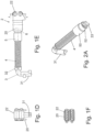
- the Fig. 1A shows a parking lock assembly 1 with a receiving body 3, a laterally projecting engagement portion 31 attached to the rear end portion thereof and a support portion 2 mounted on the front end portion by means of a guide member 5.
- the parking lock assembly 1 is installed between an adjusting mechanism, in particular a manually operated gearshift lever, and a parking lock gear in order to engage a locking member in the parking lock gear in the parking position and to disengage it outside the parking position.
- the front and rear abutments 33, 32 can be integrally formed on the receiving body 3, for example, by means of an embossing thereof.
- a holding element 20 of the support section 2 is immovably fixed relative to the guide member 5 at a front section of the guide member 5.
- the holding element 20 is U-shaped in plan view (axially to the engagement section 31) and is fastened by its U-web to the front section of the guide member 5, while the U-legs, which in plan view protrude symmetrically with respect to the longitudinal axis of the receiving body 3, carry support elements in the form of two cylinder-like rollers 22 between their front end regions, the axis of rotation of which runs perpendicular to the longitudinal axis of the receiving body 3, as can be seen from the Fig. 1B, 1C , 1D and 1E visible.
- the roller-shaped support elements actuate the respective coupling elements (not shown) for engaging and disengaging a locking element in the parking gear.
- the front section 52 of the guide member 5 merges via a shoulder 51 into a rear section of the guide member 5, which is designed as a section 50 with an expanded outer diameter compared to the front section and is supported against the front area of the spring 4.
- the front abutment 33 on which the front end face of the guide member 5 is supported, projects radially at most to the outer circumference of the front section 52 of the guide member 5.
- 3A and 3E show, simply pushed onto the receiving body 3 pre-assembled with the guide member 5 and the spring 4 from the front onto the front section 52 until it reaches a predetermined distance from the engagement section 31.
- This distance can be precisely adjusted, after which the holding element 20 on the front section 52, e.g. is fixed in the correct position by welding or gluing.
- the diameter of the receiving opening 23 is advantageously matched to the outer diameter of the front section 52, so that even if the fixation by means of the connecting means 6 should break, support against the shoulder 51 of the guide member 5 is achieved and a supporting function for actuating the parking lock is provided.
- the receiving body 3, the guide member 5 displaceably mounted thereon and the spring 4 are designed as cylindrical parts arranged coaxially to one another, whereby an exact coordination with one another and reliable function are achieved with a simple structure and easy assembly.
Landscapes
- Engineering & Computer Science (AREA)
- General Engineering & Computer Science (AREA)
- Mechanical Engineering (AREA)
- Braking Elements And Transmission Devices (AREA)
- Braking Arrangements (AREA)
- Gear-Shifting Mechanisms (AREA)
Claims (6)
- Unité structurale de verrou de stationnement apte à être installée entre un mécanisme de réglage, en particulier un levier de changement de vitesse actionné manuellement, et une roue de verrou de stationnement, afin d'enclencher un organe de verrouillage dans la roue de verrou de stationnement dans une position de stationnement et de le désenclencher hors de la position de stationnement, l'unité structurale de verrou de stationnement est pourvue d'un corps de réception (3) allongé, dont la section d'extrémité arrière détournée de la roue de verrou de stationnement dans l'état installé est pourvue d'une section de mise en prise (31) reliée rigidement au corps de réception (3), faisant saillie à partir du corps de réception (3) transversalement à l'axe longitudinal de celui-ci, et dont la section d'extrémité avant tournée vers la roue de verrou de stationnement dans l'état installé est pourvue d'une section de support (2) dépassant du côté de l'extrémité et présentant un élément de retenue (20), laquelle section de support, à l'aide d'un organe de guidage (5), est supportée de manière limitée à l'encontre de la force de ressort d'un ressort (4) disposé sur le corps de réception (3) et s'étendant axialement, et est montée mobile sur le corps de réception (3) et soutient dans sa région avant au moins un élément de support, lequel est apte à actionner des organes d'accouplement pour l'enclenchement et le désenclenchement de l'organe de verrouillage dans la roue de verrou de stationnement dans l'état installé, le ressort (4) étant supporté par sa partie arrière contre une butée (32) arrière attachée fixement au corps de réception (3), caractérisée en ce quel'élément de retenue (20) de la section de support (2) est relié fixement à l'organe de guidage (5) dans sa région arrière,que l'organe de guidage (5) est réalisé en forme de manchon et est monté de manière à glisser sur le corps de réception (3), ledit organe de guidage entourant une région partielle de la section d'extrémité avant du corps de réception (3) et étant supporté contre le ressort (4) disposé sur le corps de réception (3),que l'élément de retenue (20) est enfilé sur l'organe de guidage (5) à l'aide d'une ouverture de réception (23) adaptée par sa périphérie intérieure à une périphérie extérieure de l'organe de guidage (5) et est fixé de manière immobile par rapport à l'organe de guidage (5) de telle sorte qu'il en résulte, entre l'élément de retenue (20) et la section de mise en prise (31), une distance pré-définie pour un accouplement en position correcte au mécanisme de réglage,l'organe de guidage (5) présentant deux sections partielles se prolongeant l'une dans l'autre par l'intermédiaire d'un épaulement (51) et la section partielle arrière formant une section partielle (50) agrandie en diamètre extérieur et la section partielle avant formant une section de glissement (52) sur laquelle l'élément de retenue (20) est enfilé et fixé de manière immobile, etque la section partielle (50) agrandie de l'organe de guidage (5) est supportée sur la partie avant du ressort (4).
- Unité structurale de verrou de stationnement selon l'une des revendications précédentes, caractérisée en ce que
l'élément de retenue (20) est soudé sur l'organe de guidage (5). - Unité structurale de verrou de stationnement selon la revendication 1 ou 2, caractérisée en ce que
l'élément de retenue (20) est réalisé en forme de U avec une âme de U fixée à l'organe de guidage (5) et deux branches de U pliées vers l'avant à partir de celle-ci, branches à la région avant desquelles l'au moins un élément de support est attaché. - Unité structurale de verrou de stationnement selon l'une des revendications précédentes,
caractérisée en ce que
l'au moins un élément de support est réalisé sous la forme d'au moins un rouleau (22) qui est monté de manière à pouvoir tourner sur l'élément de retenue (20). - Unité structurale de verrou de stationnement selon l'une des revendications précédentes,
caractérisée en ce que
l'organe de guidage (5) est pressé à l'aide de la force de ressort dans une position de repos contre une butée (33) avant attachée fixement dans sa région d'extrémité avant au corps de réception (3) et peut être repoussé de manière limitée à l'encontre de la force de ressort. - Unité structurale de verrou de stationnement selon l'une des revendications précédentes,
caractérisée en ce que
la section de mise en prise est réalisée sous la forme d'une section courbée à partir du corps de réception (3).
Applications Claiming Priority (1)
| Application Number | Priority Date | Filing Date | Title |
|---|---|---|---|
| DE102014108866.2A DE102014108866B4 (de) | 2014-06-25 | 2014-06-25 | Parksperrenbaueinheit |
Publications (4)
| Publication Number | Publication Date |
|---|---|
| EP2960552A2 EP2960552A2 (fr) | 2015-12-30 |
| EP2960552A3 EP2960552A3 (fr) | 2016-03-09 |
| EP2960552B1 true EP2960552B1 (fr) | 2025-03-19 |
| EP2960552C0 EP2960552C0 (fr) | 2025-03-19 |
Family
ID=53498818
Family Applications (1)
| Application Number | Title | Priority Date | Filing Date |
|---|---|---|---|
| EP15173928.1A Active EP2960552B1 (fr) | 2014-06-25 | 2015-06-25 | Composant de frein de stationnement |
Country Status (2)
| Country | Link |
|---|---|
| EP (1) | EP2960552B1 (fr) |
| DE (1) | DE102014108866B4 (fr) |
Families Citing this family (6)
| Publication number | Priority date | Publication date | Assignee | Title |
|---|---|---|---|---|
| DE102016124391B4 (de) | 2016-12-14 | 2018-09-13 | Hugo Benzing Gmbh & Co. Kg | Auslenkmechanismus für eine Parksperre und Verfahren zur Herstellung eines solchen |
| DE202017102386U1 (de) | 2017-04-21 | 2018-04-24 | Hugo Benzing Gmbh & Co. Kg | Betätigungseinheit für eine Parksperre |
| DE102017122747A1 (de) | 2017-08-16 | 2018-08-16 | Schaeffler Technologies AG & Co. KG | Schlitteneinheit einer Parksperre eines Kraftfahrzeugs und Verfahren zum Herstellen einer solchen |
| EP3620690A1 (fr) * | 2018-09-07 | 2020-03-11 | DURA Automotive Holdings U.K., Ltd. | Système de blocage en stationnement pour une transmission d'une boîte de vitesses automatique, hybride, ou électrique d'un véhicule automobile |
| CA3117704A1 (fr) * | 2018-10-25 | 2020-04-30 | Linamar Corporation | Ensemble rouleau de verrouillage de stationnement |
| CN111173928A (zh) * | 2020-01-22 | 2020-05-19 | 海马汽车有限公司 | 一种驻车拉杆组件、驻车执行机构和驻车锁止总成 |
Family Cites Families (9)
| Publication number | Priority date | Publication date | Assignee | Title |
|---|---|---|---|---|
| US5685406A (en) * | 1996-08-05 | 1997-11-11 | General Motors Corporation | Park brake actuating mechanism for a power transmission |
| AT404703B (de) | 1997-05-06 | 1999-02-25 | Steyr Daimler Puch Ag | Parksperre für ein kraftfahrzeug |
| DE10144056B4 (de) * | 2001-09-07 | 2005-09-01 | Ina-Schaeffler Kg | Parksperre für ein Automatikgetriebe eines Kraftfahrzeuges |
| DE102005010211B4 (de) * | 2005-03-05 | 2017-06-22 | Zf Friedrichshafen Ag | Parksperrenmechanismus für ein Kraftfahrzeug, welches ein Automatgetriebe oder ein automatisiertes Handschaltgetriebe umfasst |
| DE102007007681A1 (de) | 2007-02-16 | 2008-08-21 | Audi Ag | Vorrichtung und Verfahren zum Abstellen eines Fahrzeugs mit einem automatischen Getriebe |
| DE102010028281B4 (de) * | 2010-04-28 | 2023-05-25 | Zf Friedrichshafen Ag | Parksperreneinrichtung für ein Kraftfahrzeug-Automatgetriebe |
| EP2410214B1 (fr) * | 2010-07-23 | 2013-09-04 | Magna Powertrain AG & Co. KG | Mécanisme de blocage |
| DE102010061171A1 (de) | 2010-12-10 | 2012-06-14 | Stiwa Holding Gmbh | Parksperre für ein Kraftfahrzeuggetriebe |
| DE102012012673A1 (de) | 2012-06-23 | 2013-12-24 | Daimler Ag | Kraftfahrzeugantriebsstrangvorrichtung mit einer Parksperre |
-
2014
- 2014-06-25 DE DE102014108866.2A patent/DE102014108866B4/de active Active
-
2015
- 2015-06-25 EP EP15173928.1A patent/EP2960552B1/fr active Active
Also Published As
| Publication number | Publication date |
|---|---|
| EP2960552A2 (fr) | 2015-12-30 |
| EP2960552C0 (fr) | 2025-03-19 |
| EP2960552A3 (fr) | 2016-03-09 |
| DE102014108866A1 (de) | 2015-12-31 |
| DE102014108866B4 (de) | 2017-04-06 |
Similar Documents
| Publication | Publication Date | Title |
|---|---|---|
| EP2960552B1 (fr) | Composant de frein de stationnement | |
| EP2495453B1 (fr) | Dispositif de fixation doté d'une égalisation de tolérance | |
| DE19820043C2 (de) | Schwenk- und Teleskopvorrichtung für eine Lenksäule | |
| DE102015116654B4 (de) | Parksperreneinheit | |
| EP1805427A1 (fr) | Barre de traction-compression | |
| DE202005009017U1 (de) | Toleranzausgleichsanordnung aus Kunststoff | |
| EP3601014B1 (fr) | Colonne de direction avec dispositif absorbeur d'énergie | |
| EP3304655B1 (fr) | Système de verrouillage pour un connecteur de charge | |
| DE68903549T2 (de) | Regelvorrichtung fuer eine sperrbare gasfeder. | |
| DE19919335A1 (de) | Führungshülse für die Stange einer Kopfstütze | |
| AT2249U1 (de) | Handstempel mit selbstfärbeeinrichtung | |
| DE1213170B (de) | Schnell loesbares Befestigungsglied | |
| DE112015002019T5 (de) | Lenksäule | |
| EP2816243B1 (fr) | Élément de fixation | |
| DE102016124391B4 (de) | Auslenkmechanismus für eine Parksperre und Verfahren zur Herstellung eines solchen | |
| DE202017102386U1 (de) | Betätigungseinheit für eine Parksperre | |
| EP2314914A1 (fr) | Dispositif de montage pour une lampe intégrée | |
| EP0248101B1 (fr) | Mécanisme d'alimentation des éléments de fixation montés sur une bande à un outil de pose de tels éléments | |
| DE102005057982B4 (de) | Vorrichtung zum Verriegeln eines Kofferraums von einem Fahrzeug | |
| EP3141677B1 (fr) | Systeme de manutention destine a l'entrainement d'une ferrure de bielle | |
| EP0672558A1 (fr) | Organe de verrouillage pour assembler de façon démontable deux éléments | |
| DE4010741A1 (de) | Einstellbare kabelverbindung | |
| EP1555151B1 (fr) | Store à enrouleur pour véhicule | |
| DE102018008392A1 (de) | Halterung zur Befestigung einer Gepäck-Tragvorrichtung | |
| DE3418185A1 (de) | Sicherheitsgurtaufroller |
Legal Events
| Date | Code | Title | Description |
|---|---|---|---|
| PUAI | Public reference made under article 153(3) epc to a published international application that has entered the european phase |
Free format text: ORIGINAL CODE: 0009012 |
|
| AK | Designated contracting states |
Kind code of ref document: A2 Designated state(s): AL AT BE BG CH CY CZ DE DK EE ES FI FR GB GR HR HU IE IS IT LI LT LU LV MC MK MT NL NO PL PT RO RS SE SI SK SM TR |
|
| AX | Request for extension of the european patent |
Extension state: BA ME |
|
| PUAL | Search report despatched |
Free format text: ORIGINAL CODE: 0009013 |
|
| AK | Designated contracting states |
Kind code of ref document: A3 Designated state(s): AL AT BE BG CH CY CZ DE DK EE ES FI FR GB GR HR HU IE IS IT LI LT LU LV MC MK MT NL NO PL PT RO RS SE SI SK SM TR |
|
| AX | Request for extension of the european patent |
Extension state: BA ME |
|
| RIC1 | Information provided on ipc code assigned before grant |
Ipc: F16H 63/34 20060101AFI20160203BHEP |
|
| 17P | Request for examination filed |
Effective date: 20160909 |
|
| RBV | Designated contracting states (corrected) |
Designated state(s): AL AT BE BG CH CY CZ DE DK EE ES FI FR GB GR HR HU IE IS IT LI LT LU LV MC MK MT NL NO PL PT RO RS SE SI SK SM TR |
|
| STAA | Information on the status of an ep patent application or granted ep patent |
Free format text: STATUS: EXAMINATION IS IN PROGRESS |
|
| 17Q | First examination report despatched |
Effective date: 20171004 |
|
| GRAP | Despatch of communication of intention to grant a patent |
Free format text: ORIGINAL CODE: EPIDOSNIGR1 |
|
| STAA | Information on the status of an ep patent application or granted ep patent |
Free format text: STATUS: GRANT OF PATENT IS INTENDED |
|
| INTG | Intention to grant announced |
Effective date: 20241028 |
|
| GRAS | Grant fee paid |
Free format text: ORIGINAL CODE: EPIDOSNIGR3 |
|
| GRAA | (expected) grant |
Free format text: ORIGINAL CODE: 0009210 |
|
| STAA | Information on the status of an ep patent application or granted ep patent |
Free format text: STATUS: THE PATENT HAS BEEN GRANTED |
|
| AK | Designated contracting states |
Kind code of ref document: B1 Designated state(s): AL AT BE BG CH CY CZ DE DK EE ES FI FR GB GR HR HU IE IS IT LI LT LU LV MC MK MT NL NO PL PT RO RS SE SI SK SM TR |
|
| REG | Reference to a national code |
Ref country code: GB Ref legal event code: FG4D Free format text: NOT ENGLISH |
|
| REG | Reference to a national code |
Ref country code: CH Ref legal event code: EP |
|
| REG | Reference to a national code |
Ref country code: DE Ref legal event code: R096 Ref document number: 502015017050 Country of ref document: DE |
|
| REG | Reference to a national code |
Ref country code: IE Ref legal event code: FG4D Free format text: LANGUAGE OF EP DOCUMENT: GERMAN |
|
| U01 | Request for unitary effect filed |
Effective date: 20250319 |
|
| U07 | Unitary effect registered |
Designated state(s): AT BE BG DE DK EE FI FR IT LT LU LV MT NL PT RO SE SI Effective date: 20250325 |
|
| PG25 | Lapsed in a contracting state [announced via postgrant information from national office to epo] |
Ref country code: RS Free format text: LAPSE BECAUSE OF FAILURE TO SUBMIT A TRANSLATION OF THE DESCRIPTION OR TO PAY THE FEE WITHIN THE PRESCRIBED TIME-LIMIT Effective date: 20250619 |
|
| PG25 | Lapsed in a contracting state [announced via postgrant information from national office to epo] |
Ref country code: NO Free format text: LAPSE BECAUSE OF FAILURE TO SUBMIT A TRANSLATION OF THE DESCRIPTION OR TO PAY THE FEE WITHIN THE PRESCRIBED TIME-LIMIT Effective date: 20250619 |
|
| PG25 | Lapsed in a contracting state [announced via postgrant information from national office to epo] |
Ref country code: HR Free format text: LAPSE BECAUSE OF FAILURE TO SUBMIT A TRANSLATION OF THE DESCRIPTION OR TO PAY THE FEE WITHIN THE PRESCRIBED TIME-LIMIT Effective date: 20250319 |
|
| PG25 | Lapsed in a contracting state [announced via postgrant information from national office to epo] |
Ref country code: GR Free format text: LAPSE BECAUSE OF FAILURE TO SUBMIT A TRANSLATION OF THE DESCRIPTION OR TO PAY THE FEE WITHIN THE PRESCRIBED TIME-LIMIT Effective date: 20250620 |
|
| U20 | Renewal fee for the european patent with unitary effect paid |
Year of fee payment: 11 Effective date: 20250630 |
|
| PG25 | Lapsed in a contracting state [announced via postgrant information from national office to epo] |
Ref country code: SM Free format text: LAPSE BECAUSE OF FAILURE TO SUBMIT A TRANSLATION OF THE DESCRIPTION OR TO PAY THE FEE WITHIN THE PRESCRIBED TIME-LIMIT Effective date: 20250319 |
|
| PG25 | Lapsed in a contracting state [announced via postgrant information from national office to epo] |
Ref country code: ES Free format text: LAPSE BECAUSE OF FAILURE TO SUBMIT A TRANSLATION OF THE DESCRIPTION OR TO PAY THE FEE WITHIN THE PRESCRIBED TIME-LIMIT Effective date: 20250319 |
|
| PG25 | Lapsed in a contracting state [announced via postgrant information from national office to epo] |
Ref country code: PL Free format text: LAPSE BECAUSE OF FAILURE TO SUBMIT A TRANSLATION OF THE DESCRIPTION OR TO PAY THE FEE WITHIN THE PRESCRIBED TIME-LIMIT Effective date: 20250319 |
|
| PG25 | Lapsed in a contracting state [announced via postgrant information from national office to epo] |
Ref country code: CZ Free format text: LAPSE BECAUSE OF FAILURE TO SUBMIT A TRANSLATION OF THE DESCRIPTION OR TO PAY THE FEE WITHIN THE PRESCRIBED TIME-LIMIT Effective date: 20250319 |
|
| PG25 | Lapsed in a contracting state [announced via postgrant information from national office to epo] |
Ref country code: SK Free format text: LAPSE BECAUSE OF FAILURE TO SUBMIT A TRANSLATION OF THE DESCRIPTION OR TO PAY THE FEE WITHIN THE PRESCRIBED TIME-LIMIT Effective date: 20250319 |
|
| PG25 | Lapsed in a contracting state [announced via postgrant information from national office to epo] |
Ref country code: IS Free format text: LAPSE BECAUSE OF FAILURE TO SUBMIT A TRANSLATION OF THE DESCRIPTION OR TO PAY THE FEE WITHIN THE PRESCRIBED TIME-LIMIT Effective date: 20250719 |
|
| PLBE | No opposition filed within time limit |
Free format text: ORIGINAL CODE: 0009261 |
|
| STAA | Information on the status of an ep patent application or granted ep patent |
Free format text: STATUS: NO OPPOSITION FILED WITHIN TIME LIMIT |
|
| REG | Reference to a national code |
Ref country code: CH Ref legal event code: H13 Free format text: ST27 STATUS EVENT CODE: U-0-0-H10-H13 (AS PROVIDED BY THE NATIONAL OFFICE) Effective date: 20260127 |
|
| REG | Reference to a national code |
Ref country code: CH Ref legal event code: L10 Free format text: ST27 STATUS EVENT CODE: U-0-0-L10-L00 (AS PROVIDED BY THE NATIONAL OFFICE) Effective date: 20260128 |
|
| PG25 | Lapsed in a contracting state [announced via postgrant information from national office to epo] |
Ref country code: MC Free format text: LAPSE BECAUSE OF FAILURE TO SUBMIT A TRANSLATION OF THE DESCRIPTION OR TO PAY THE FEE WITHIN THE PRESCRIBED TIME-LIMIT Effective date: 20250319 |
|
| 26N | No opposition filed |
Effective date: 20251222 |
|
| GBPC | Gb: european patent ceased through non-payment of renewal fee |
Effective date: 20250625 |
|
| PG25 | Lapsed in a contracting state [announced via postgrant information from national office to epo] |
Ref country code: GB Free format text: LAPSE BECAUSE OF NON-PAYMENT OF DUE FEES Effective date: 20250625 |
|
| PG25 | Lapsed in a contracting state [announced via postgrant information from national office to epo] |
Ref country code: IE Free format text: LAPSE BECAUSE OF NON-PAYMENT OF DUE FEES Effective date: 20250625 |
|
| PG25 | Lapsed in a contracting state [announced via postgrant information from national office to epo] |
Ref country code: CH Free format text: LAPSE BECAUSE OF NON-PAYMENT OF DUE FEES Effective date: 20250630 |