EP2959072B1 - Dachziegelsystem - Google Patents
Dachziegelsystem Download PDFInfo
- Publication number
- EP2959072B1 EP2959072B1 EP14709570.7A EP14709570A EP2959072B1 EP 2959072 B1 EP2959072 B1 EP 2959072B1 EP 14709570 A EP14709570 A EP 14709570A EP 2959072 B1 EP2959072 B1 EP 2959072B1
- Authority
- EP
- European Patent Office
- Prior art keywords
- tile
- roof
- roof tile
- tiles
- cassette
- Prior art date
- Legal status (The legal status is an assumption and is not a legal conclusion. Google has not performed a legal analysis and makes no representation as to the accuracy of the status listed.)
- Active
Links
Images


Classifications
-
- E—FIXED CONSTRUCTIONS
- E04—BUILDING
- E04D—ROOF COVERINGS; SKY-LIGHTS; GUTTERS; ROOF-WORKING TOOLS
- E04D1/00—Roof covering by making use of tiles, slates, shingles, or other small roofing elements
- E04D1/29—Means for connecting or fastening adjacent roofing elements
- E04D1/2907—Means for connecting or fastening adjacent roofing elements by interfitted sections
- E04D1/2914—Means for connecting or fastening adjacent roofing elements by interfitted sections having fastening means or anchors at juncture of adjacent roofing elements
- E04D1/2918—Means for connecting or fastening adjacent roofing elements by interfitted sections having fastening means or anchors at juncture of adjacent roofing elements the fastening means taking hold directly on adjacent elements of succeeding rows
-
- E—FIXED CONSTRUCTIONS
- E04—BUILDING
- E04D—ROOF COVERINGS; SKY-LIGHTS; GUTTERS; ROOF-WORKING TOOLS
- E04D1/00—Roof covering by making use of tiles, slates, shingles, or other small roofing elements
- E04D1/29—Means for connecting or fastening adjacent roofing elements
- E04D1/2907—Means for connecting or fastening adjacent roofing elements by interfitted sections
- E04D1/2914—Means for connecting or fastening adjacent roofing elements by interfitted sections having fastening means or anchors at juncture of adjacent roofing elements
- E04D1/2916—Means for connecting or fastening adjacent roofing elements by interfitted sections having fastening means or anchors at juncture of adjacent roofing elements the fastening means taking hold directly on adjacent elements of the same row
-
- E—FIXED CONSTRUCTIONS
- E04—BUILDING
- E04D—ROOF COVERINGS; SKY-LIGHTS; GUTTERS; ROOF-WORKING TOOLS
- E04D1/00—Roof covering by making use of tiles, slates, shingles, or other small roofing elements
- E04D1/30—Special roof-covering elements, e.g. ridge tiles, gutter tiles, gable tiles, ventilation tiles
-
- E—FIXED CONSTRUCTIONS
- E04—BUILDING
- E04D—ROOF COVERINGS; SKY-LIGHTS; GUTTERS; ROOF-WORKING TOOLS
- E04D1/00—Roof covering by making use of tiles, slates, shingles, or other small roofing elements
- E04D1/34—Fastenings for attaching roof-covering elements to the supporting elements
-
- E—FIXED CONSTRUCTIONS
- E04—BUILDING
- E04D—ROOF COVERINGS; SKY-LIGHTS; GUTTERS; ROOF-WORKING TOOLS
- E04D12/00—Non-structural supports for roofing materials, e.g. battens, boards
- E04D12/004—Battens
-
- F—MECHANICAL ENGINEERING; LIGHTING; HEATING; WEAPONS; BLASTING
- F24—HEATING; RANGES; VENTILATING
- F24S—SOLAR HEAT COLLECTORS; SOLAR HEAT SYSTEMS
- F24S20/00—Solar heat collectors specially adapted for particular uses or environments
- F24S20/60—Solar heat collectors integrated in fixed constructions, e.g. in buildings
- F24S20/69—Solar heat collectors integrated in fixed constructions, e.g. in buildings in the form of shingles or tiles
-
- E—FIXED CONSTRUCTIONS
- E04—BUILDING
- E04D—ROOF COVERINGS; SKY-LIGHTS; GUTTERS; ROOF-WORKING TOOLS
- E04D1/00—Roof covering by making use of tiles, slates, shingles, or other small roofing elements
- E04D1/12—Roofing elements shaped as plain tiles or shingles, i.e. with flat outer surface
-
- E—FIXED CONSTRUCTIONS
- E04—BUILDING
- E04D—ROOF COVERINGS; SKY-LIGHTS; GUTTERS; ROOF-WORKING TOOLS
- E04D1/00—Roof covering by making use of tiles, slates, shingles, or other small roofing elements
- E04D1/34—Fastenings for attaching roof-covering elements to the supporting elements
- E04D2001/3444—Fastenings for attaching roof-covering elements to the supporting elements characterised by the roof covering or structure with integral or premounted fastening means
- E04D2001/3447—Fastenings for attaching roof-covering elements to the supporting elements characterised by the roof covering or structure with integral or premounted fastening means the fastening means being integral or premounted to the roof covering
-
- E—FIXED CONSTRUCTIONS
- E04—BUILDING
- E04D—ROOF COVERINGS; SKY-LIGHTS; GUTTERS; ROOF-WORKING TOOLS
- E04D1/00—Roof covering by making use of tiles, slates, shingles, or other small roofing elements
- E04D1/34—Fastenings for attaching roof-covering elements to the supporting elements
- E04D2001/3452—Fastenings for attaching roof-covering elements to the supporting elements characterised by the location of the fastening means
- E04D2001/3455—Fastenings for attaching roof-covering elements to the supporting elements characterised by the location of the fastening means on the internal surface of the roof covering elements
-
- E—FIXED CONSTRUCTIONS
- E04—BUILDING
- E04D—ROOF COVERINGS; SKY-LIGHTS; GUTTERS; ROOF-WORKING TOOLS
- E04D1/00—Roof covering by making use of tiles, slates, shingles, or other small roofing elements
- E04D1/34—Fastenings for attaching roof-covering elements to the supporting elements
- E04D2001/3452—Fastenings for attaching roof-covering elements to the supporting elements characterised by the location of the fastening means
- E04D2001/3461—Fastenings for attaching roof-covering elements to the supporting elements characterised by the location of the fastening means on the lateral edges of the roof covering elements
-
- E—FIXED CONSTRUCTIONS
- E04—BUILDING
- E04D—ROOF COVERINGS; SKY-LIGHTS; GUTTERS; ROOF-WORKING TOOLS
- E04D1/00—Roof covering by making use of tiles, slates, shingles, or other small roofing elements
- E04D1/34—Fastenings for attaching roof-covering elements to the supporting elements
- E04D2001/3452—Fastenings for attaching roof-covering elements to the supporting elements characterised by the location of the fastening means
- E04D2001/3467—Fastenings for attaching roof-covering elements to the supporting elements characterised by the location of the fastening means through apertures, holes or slots
-
- E—FIXED CONSTRUCTIONS
- E04—BUILDING
- E04D—ROOF COVERINGS; SKY-LIGHTS; GUTTERS; ROOF-WORKING TOOLS
- E04D1/00—Roof covering by making use of tiles, slates, shingles, or other small roofing elements
- E04D1/34—Fastenings for attaching roof-covering elements to the supporting elements
- E04D2001/3488—Fastenings for attaching roof-covering elements to the supporting elements characterised by the type of roof covering elements being fastened
- E04D2001/3494—Fastenings for attaching roof-covering elements to the supporting elements characterised by the type of roof covering elements being fastened made of rigid material having a flat external surface
-
- Y—GENERAL TAGGING OF NEW TECHNOLOGICAL DEVELOPMENTS; GENERAL TAGGING OF CROSS-SECTIONAL TECHNOLOGIES SPANNING OVER SEVERAL SECTIONS OF THE IPC; TECHNICAL SUBJECTS COVERED BY FORMER USPC CROSS-REFERENCE ART COLLECTIONS [XRACs] AND DIGESTS
- Y02—TECHNOLOGIES OR APPLICATIONS FOR MITIGATION OR ADAPTATION AGAINST CLIMATE CHANGE
- Y02B—CLIMATE CHANGE MITIGATION TECHNOLOGIES RELATED TO BUILDINGS, e.g. HOUSING, HOUSE APPLIANCES OR RELATED END-USER APPLICATIONS
- Y02B10/00—Integration of renewable energy sources in buildings
- Y02B10/20—Solar thermal
-
- Y—GENERAL TAGGING OF NEW TECHNOLOGICAL DEVELOPMENTS; GENERAL TAGGING OF CROSS-SECTIONAL TECHNOLOGIES SPANNING OVER SEVERAL SECTIONS OF THE IPC; TECHNICAL SUBJECTS COVERED BY FORMER USPC CROSS-REFERENCE ART COLLECTIONS [XRACs] AND DIGESTS
- Y02—TECHNOLOGIES OR APPLICATIONS FOR MITIGATION OR ADAPTATION AGAINST CLIMATE CHANGE
- Y02E—REDUCTION OF GREENHOUSE GAS [GHG] EMISSIONS, RELATED TO ENERGY GENERATION, TRANSMISSION OR DISTRIBUTION
- Y02E10/00—Energy generation through renewable energy sources
- Y02E10/40—Solar thermal energy, e.g. solar towers
- Y02E10/44—Heat exchange systems
Definitions
- the present invention relates to a roof tile system, and a method of installing a roof tile system.
- Tiles are commonly used as a covering for pitched roofs, such as the roofs of houses. Tiles made from clay, concrete or slate are particularly common due to their durability, fire resistance, and their ability to shed water and resist the elements (wind). Many tile materials can be manufactured in a range of shapes to provide different appearances. For example, clay tiles are manufactured by baking plates of molded clay into a relatively lightweight tile and similarly, concrete tiles, which are heavier and more durable, can be poured into moulds. Other materials, such as slate, may also be chosen for their natural appearance.
- roof tiles are fixed to a roof by first installing an underlying waterproof membrane, installing metal flashing (where needed), and then fixing to battens.
- the battens are arranged horizontally and substantially parallel to each other and are typically fixed to the roof with nails.
- the battens provide a support structure onto which the tiles are supported and fixed.
- the tiles are laid onto the battens at the bottom edge of the roof and nailed to the battens via holes formed in the tiles during manufacture. Rows of tiles are then fixed to successive horizontal battens starting from the lower edge of the roof and working up such that the lower edge of one row of tiles overlaps the tiles of the row immediately below. Typically, the tiles of a given row will cover the nails holding the tiles of the row immediately below to the batten. Finally, when all the rows are fixed to the battens a ridge tile is fitted to the apex of the roof.
- the lower end of the tile may be fixed to the tile below with a nail or a mechanical clip.
- the lower end may not be fixed at all and the weight of the tile or, where each tile interlocks with adjacent tiles, the combined weight of a row of tiles, is used to resist wind-lift (that is, lifting of the tiles by the wind).
- GB2473447 describes a tile holding system in which conventional battens are replaced with a tile holding device that acts to hold the upper end of one row of tiles, and the lower end of an adjacent row of tiles, to the roof.
- DE1166993 describes a system in which a C shaped metal plate is used to fix a roof tile to a roof.
- EP2304122 describes an inter-lockable tile system.
- roof tiles that are easier to install, and easier to remove without causing damage to the tiles.
- a roof tile system according to claim 1.
- the roof tile system comprises a first roof tile and a tile-holding device.
- the roof tile comprises, at a first end portion, a first attaching means for attaching the first roof tile to a second roof tile when the first roof tile and the second roof tile are arranged together on a roof.
- the first roof tile further comprises a flange extending from a first end portion.
- the tile-holding device comprises a channel for receiving the flange so as to inhibit lifting of the first end portion away from the roof.
- each roof tile is fixed to the roof via only one tile holding device thereby avoiding certain problems in the prior art without the need to fix the roof tiles to a batten with nails or screws.
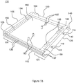
- FIGS 1a and 1b show an exemplary roof tile 100.
- the tile 100 has a planar front surface 102 that, in use, forms part of a tiled roof surface, and a back surface 104, that, in use is not visible.
- the tile 100 has a upper end 106 and a lower end 108, upper and lower ends referring to the relative heights of the ends of the tile, when the tile is installed.
- the tile also has a first, left, edge 110 and a second, right, edge 112 (as viewed looking in the plane of the page).
- the tile 100 is held in place on a roof by a tile-holding device, described in detail below, that is located at the upper end 106 of the tile.
- the lower end 108 of the tile sits on one or more tiles in a lower row, and mechanically couples to the tiles in the lower row, by tile interconnects that are also described in detail below.
- the recesses 116 are arranged to receive corresponding protrusions 118 located in a lower portion 120 of an adjacent tile.
- the protrusions 118 are described in detail below.
- the two recesses 116 of a tile 100 of, for example, a lower row of tiles may receive the two corresponding protrusions 118 of a tile of, for example, an upper row of tiles.
- the tiles of, for example, an upper row of tiles may be staggered by, for example, half a tile width with respect to, for example, a lower row of tiles.
- one of the two recesses 116 of a tile of the lower row of tiles may receive one of the two protrusions 118 of a first adjacent tile of the upper row of tiles
- the other one of the two recesses 116 of the tile of the lower row of tiles may receive one of the two protrusions 118 of a second adjacent tile of the upper row of tiles.
- the tile 100 is composed of a resin that binds together reconstituted slate-granules in a matrix.
- the granules and resin are mixed together with the resin in liquid form, and injected into a mould that acts as a cast for the roof tile.
- the resin may then be cured by the application of one or more of heat, pressure, and vibration.
- a hardener may added to aid solidification of the resin and hold the slate granules in a matrix.
- the mould is than opened and the rigid solidified tile is removed.
- the slate material comprises 80% of the mixture by weight.
- the slate granules may be formed from recycled slate such as damaged slate tiles and off cuts, or from waste quarried slate, thereby reducing the cost of the slate material and therefore the composite tile.
- the slate granules may be formed by grinding larger slate pieces to a power with granules in the diameter range 1 mm to 3 mm.
- the matrix tiles 100 can be cast or moulded into a variety of shapes and enables different profiles and textures to be formed on the planar surface of the tile, to provide different aesthetic appearances.
- embodiments described herein are described as planar tiles, it will be understood that embodiments of the invention may also comprise non-planar surfaces.
- left interlock recess 122 On the left edge 110 of the tile 100 there is a left interlock recess 122 in the front surface 102 running along the length of the left edge 110. In the left interlock recess 122, are a series of ridges 124 and valleys 126. On the right edge 112 of the tile 100 there is a right interlock recess 128 in the bottom surface 104 running along the length of the right edge 112. In the right interlock recess 128 are a series of ridges 130 and valleys 132.
- the ridges 130 of the right interlock recess 128 are arranged to fit in the valleys 126 of the left interlock recess 122, and the ridges 124 of the left interlock recess 122 are arranged to fit in the valleys 132 of the right interlock recess 128. Therefore, when two tiles are aligned next to each other (that is, in a row), the ridges 124, 130 interlock to prevent lateral movement of a given tile with respect to an adjacent tile (in that row).
- the left interlock recess 122 has deeper valleys 126 than the corresponding valleys 132 in the right interlock recess 128. In other words, there is always a gap between the ridges 130 of the right interlock recess 128 and the valleys 126 of the left interlock recess 122 even where there is otherwise a tight seal between adjacent tiles 100. In use, this results in the formation of channels running along the left interlock recess 122 of each tile that act to guide and drain water that collects between the tiles.
- the ridges 124, 130 and valleys 126, 132 may have any suitable cross-sectional profile. In some embodiments, the ridges 124, 130 and valleys 126, 132 have a square cross-sectional profile. In some embodiments, the ridges 124, 130 and valleys 126, 132 may be bevelled or chamfered for ease of moulding.
- the upper end 106 of the tile 100 has an upper recess 134 in the front surface 102 of the tile 100 running along the length of the upper end 106. As shown in figure 1b , in some embodiments, the upper recess 134 also protrudes beyond the plane of the bottom surface 104. In the upper recess 134, there are profile features 136 also running along the length of the tile. The profile features 136 of the upper recess form an engaging flange that is arranged to engage with a tile-holding device as described in detail below.
- the upper recess 134 includes a channel 138 that is arranged to provide a fluidic connection with the valleys 126 in the left interlock recess 122.
- the channel 138 carries water that would otherwise collect in the upper recess 134 toward the left edge 110 of the tile. This water is then drained by the valleys 126 formed in the left interlock recess 122 towards a tile 100 in the row below, and so on, until the water reaches the edge of the roof and can be drained by a conventional guttering system.
- the channel 138 is arranged to be to be closer to the upper end 106 of the tile 100 at the right edge 112 of the tile than at the left edge 110 of the tile 100.
- the channel 138 includes a ridge 139, as shown in the inset to figure 1a , which guides the water flowing along the channel 138 into valleys 126 formed in the left interlock recess 122.
- the valleys 126 in the left interlock recess 122 are deeper, with respect to the front surface 102, at the upper end 106 of the tile 100 than at the lower end 108 of the tile 100.
- the depth of the valleys 126 vary from ⁇ 5 mm at the upper end 106 to ⁇ 3 mm at the lower end 108. Varying the depth of the valleys 126 in this way ensures that there is sufficient depth in the valleys 126 at the upper end 106 of the tile 100 to allow any water caught in channel 138 in the upper recess 134 to be drained.
- the lower end 108 of the tile 100 has a lower recess 140 in the back surface 104 of the tile running along the length of the lower end 108.
- the depth of the lower recess 140 is arranged such that, in use, the lower recess 140 corresponds in depth with the upper recess 134 of a tile 100 in the row below.
- the lower recess 140 forms an overlaying portion of the tile 100 which overlays at least part of the front surface 102 of at least one of the tiles in the row below, such that the lower recess 140 acts to direct rain water that is driven under the tile 100 into the channel 138 of a tile 100 in the row below.
- the overlaying portion of the tile 100 therefore retains a thin slate-like profile on the roof when installed, reducing the thickness of the lower end 108 so as to minimise wind lift, while providing enough depth to the tile 100 to accommodate fluid cassettes as described below with reference to figure 5 .
- the protrusions 118 may be, for example, studs, which correspond in size and shape with the holes 116 in the upper portion 114 of the front surface 102 of the tile 100.
- the protrusions 118 of one tile 100 can be inserted into the holes 116 of another tile 100 to form an interference fit (i.e. fastening is achieved at least partly by friction after the parts are pushed together, alternatively referred to in the below as a compression fit) or a snap fit.
- an interference fit i.e. fastening is achieved at least partly by friction after the parts are pushed together, alternatively referred to in the below as a compression fit
- a snap fit i.e. fastening is achieved at least partly by friction after the parts are pushed together, alternatively referred to in the below as a compression fit
- the lower end 108 of one tile 100 is rigidly, but removably, held by the mating protrusions 118 and holes 116 to the upper end 106 of an adjacent tile 100.
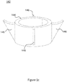
- the protrusions 118 include an expansion mechanism 142 that is compressed during fitting of the tile, and expands to provide a compression fitting thus preventing lifting of the lower end 108 of the tile 100 after fitting.
- Figure 1c shows an exemplary expansion mechanism 142.
- the expansion mechanism 142 shown is a collar 144 that, in use, is attached to each of the protrusions 118 on the lower surface of the tile 100.
- the collar 144 comprises flexible hooks 146 that enable the collar to be inserted into and through the holes 116 in the upper portion 114 of the front surface 102 of an adjacent tile 100.
- the hooks 146 enable the expansion mechanism 142 to be inserted in to the holes 116 relatively easily, but make removal of the expansion mechanism difficult, thereby, in use, holding the lower end 108 of one tile 100 in contact with the upper end 106 of a tile 100 in a row below.
- the expansion mechanism 142 may be formed with the protrusions 118 during manufacture. In some embodiments, the expansion mechanism 142 may be formed separately and attached to the protrusions 118 using an adhesive, or any other suitable fixing method, either during manufacture or during installation of the tiles 100.
- Figure Id shows a cross-sectional view of an exemplary engaging flange 150 formed towards the upper end 106 of the tile 100.
- the flange 150 extends in a direction away from the upper end of the front surface 102 of the tile 100.
- the flange 150 comprises an upper surface 152, and a lower surface 154.
- the flange 150 extends the profile of the upper surface 152 increases at a shallow angle to a peak 156 and then drops sharply to form a deep recess 158 and then rises again to the upper end 106 of the tile 100.
- the deep recess 158 can be engaged with a tile-holding device as described below.
- the flange 150 extends the profile of the lower surface 154 curves to a shallow recess 160 and then curves and rises to the upper end 106 of the tile 100.
- the profile of the lower surface 154 is arranged to correspond to the profile of a tile-holding device as described below and act as a surface on which the tile can be pivoted.
- the back surface 104 of the tile 100 comprises a cassette recess 180 arranged accommodate a fluid cassette that may form part of a solar energy capture system.
- cassette mounts 182 are cylindrical protrusions extending from the surface of the cassette recess 180 and have a diameter arranged to engage a fluid cassette as described below.
- 4 cassette mounts 182 are shown in figure 1b , it will be understood that other numbers of cassette mounts 182 may be used depending on the configuration of cassette that is to be received in the cassette recess 180.
- inlet channels 184 extending from the upper end of the cassette recess 180 in the back surface 104 through the flange 150 and toward the upper end 106 of the tile 100.
- Each inlet channel terminates with an inlet hole 186 passing through to the upper surface 152 of the flange 150.
- outlet channels 188 extending from the lower end of the cassette recess 180 in the back surface 104.
- the back surface 104 of the tile 100 comprises other recesses that are not arranged to receive any part such as the recesses 190 formed in the back surface 104 of the tile 100 shown in figure 1b .
- These other recesses reduce the weight of the tile, making installation easier and therefore quicker, and also reduce the amount of material needed to form the tile 100.
- FIG. 2 shows a tile-holding device 200 arranged to hold tiles 100 to a roof.
- the tile-holding device 200 comprises a base portion 202, a back portion 204 and an engagement portion 206.
- the base portion 202 is fixed to the joists of a roof with, for example, nails or screws.
- the base portion 202 comprises a raised central spine 208 and a raised lower spine 210.
- the central spine 208 is supported by two stiffening ribs 212 that extend from the bottom surface of the tile-holding device 200.
- the stiffening ribs 212 increase the rigidity of the tile-holding device 200 and support the central spine 208 when in use.
- the central spine 208 is arranged to interface with the shallow recess 160 in the lower surface 154 of the flange 150.
- the base portion 202 curves from the central spine 208 to the lower spine 210 with a curvature corresponding to the curvature of the lower surface 154 of the flange 150 such that the central and lower spines 208, 210 act to seat the flange 150 in the correct position, when the flange 150 is engaged with the tile-holding device 200.
- a shallow channel that may have a planar bottom that acts as a visual guide to position nails, screws or other fixing means used to fix the tile-holding device 200 to the roof as described in detail below.
- the base portion 202 is described with a particular profile it will be understood that other profiles may be used to achieve the same function. Indeed, in certain examples, the base portion 202 may be substantially planar.
- the back portion 204 extends at a substantially perpendicular angle from the base portion 202 and is arranged to support the engagement portion 206. It will be understood that the back portion 204 may extend from any suitable point on the base portion 202.
- the engagement portion 206 extends from the end of the back portion 204 at a substantially perpendicular angle. As the engagement portion 206 extends, it curves toward the base portion 202; the curve forms an upper arc and defines a channel between the engagement portion 206 and the base portion 202.
- the degree of curvature of the upper arc of the engagement portion 206, and the extent to which the engagement portion 206 extends from the back portion 204 are chosen such that the engaging flange 150 at the upper edge 106 of the tile 100 can be inserted between the engagement portion 206 and the base portion 202 when the plane of the tile 100 is orientated at an angle with respect to the plane of the base portion 202.
- the dimensions of the flange 150 and the engagement portion 206 are such that when the angle between the plane of the tile 100 and the plane of the base portion 202 is about 45 degrees, the flange 150 can fit between the engagement portion 206 and the base portion 202. At this angle, the flange 150 can be inserted into, and removed from, the channel between the engagement portion 206 and the base portion 202, and thereby the tile 100 can be engaged or disengaged with the tile-holding device 200.
- the flange 150 When the flange 150 is inserted in the channel between the engagement portion 206 and the base portion 202, if the tile 100 is orientated such that the plane of the tile 100 aligns substantially with the plane of the base portion 202 (that is, the plane of the front surface of the tile 100 lies substantially in the plane of the surface of the roof), then the end of the engagement portion 206 hooks into the deep recess 158 of the flange 150 such that the upper end 106 of the tile 100 hooks under the upper arc of the engagement portion 206 of the tile-holding device 200. The flange 150 then becomes trapped. In this way, the tile-holding device 200 holds the tile 100 such that the tile 100 cannot move with respect to the tile-holding device 200.
- the central and lower spines 208, 210 and the engagement portion 206 act to prevent the tile 100 from sliding down the roof and the engagement portion 206 further prevents the upper end 106 from being lifted away from the roof without the need for additional fixings such as nails or screws.
- the tile-holding device 200 is typically made of a resilient material such that as the plane of the tile 100 is brought in line with the plane of the base portion 202, the flange 150 acts to force a separation between the base portion 202 and the engagement portion 206, and a reactive force is thereby applied to the flange 150 further holding the flange 150 in place. In addition to the hooking action of the upper arc, this acts to inhibit lateral movement of the tile with respect to an axis defined by the length of the tile-holding device 100 further. This ensures that the tile 100 cannot easily be removed without raising the lower end 108 of the tile 100 to about 45 degrees. However, if necessary, the tile 100 can be removed more easily than conventional tiles can be, and without potentially damaging the tile 100.
- the tile holding device 200 is typically made from an extruded medium-density or high-density plastics material.
- the tile-holding device 200 may be made from one or more of polypropylene and HDPE.
- the tile holding device 200 may be made from a metal material; the tile holding device 200 may be made from extruded aluminium.
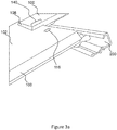
- Figure 3a shows a cross-section of two connected tiles 100.
- the extent of the recess from the lower end 108 of the tile 100 is arranged such that, when two tiles 100 are connected by the mating protrusions 118 and holes 116, the lower recess 140 of the higher placed tile 100 overlies the upper portion 114 of the front surface 102 of the higher placed tile 100.
- the holes 116 of the lower placed tile 100 are covered by the higher placed tile 100, such that the higher placed tile 100 prevents water from collecting in the holes 116 of the lower placed tile 100 and provides a roof surface with no apparent fixtures.
- the corresponding upper and lower recesses 134, 140 enable a lowered upper end 106 of a lower placed tile 100 and an overlying and lowered lower end 108 of a higher placed tile 100 such that the step between the front surfaces of the two tiles is minimised, thus reducing the edge on which wind can catch the lower end 108 of a given tile. This in turn reduces the effect of wind-lift (that is, uplifting of a tile by the wind).
- the lower surface 154 of the flange 150 may be formed to accommodate the head of a screw or nail that is used to secure the tile-holding device 200 to the roof.
- figure 3b shows an exemplary flange 150 in which the lower surface 154 of the flange 150 comprises a recess 155 large enough to accommodate a screw or nail head.
- protrusions 118 and holes 116 used to fix the lower end 108 of one tile 100 to the upper end 106 of an adjacent tile 100
- the holes 116 could be replaced with slots, or even a groove extending across the width of the front face 102 of the tile 100, with one or more corresponding protruding features in the lower recess 140.
- the tile-holding devices 200 are arranged substantially horizontally on the roof 400, typically perpendicular to the joists 402 of the roof.
- the tile-holding device 200 may be fixed to the roof joists using one or more of nails, screws, and adhesive.
- the tile-holding device 200 is fixed to the roof joists at the shallow channel between the central and lower spines 208, 210.
- the tile-holding device 200 may be fixed to every joist 402 or, for example, every other joist 402, or at whatever interval is appropriate for the weight of the tiles 100 and the method of fixing the tile-holding device 200 to the joist 400.
- the tile-holding devices 200 are spaced apart along the incline of the roof 400 by a predetermined distance that is dictated by the size of the roof tile 100.
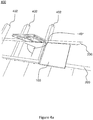
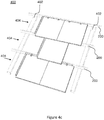
- the flange 150 of the tile is inserted into the channel between the engagement portion 206 and the base portion 202 of a tile-holding device 200, in a first orientation, at approximately 45 degrees to the plane of the roof 400 (and the plane of the base portion 202 of the tile-holding device 200), as shown in figure 4a .
- the tile 100 is then moved (as shown in figure 4b ) to a second orientation, such that the flange 150 engages with the tile-holding device 200 to form a locking fit.
- the tiles 100 are inserted in rows 404, starting with the lowest row 404 (that is, the row at the lowest edge of the roof 400).
- a first tile 100 is fitted to the tile-holding device 200 as described above with reference to figures 4a and 4b .
- installation begins at the right-most end of the roof 400 (from the perspective of the installer looking at the roof 400).
- a second tile 100 is fitted by aligning the right edge 112 of the second tile 100 with the left edge 110 of the first tile 100 such that the ridges 124, 130 and respective valleys 126, 132 in the respective interlocking recesses 122, 128 of the first and second tiles interlock appropriately.
- Subsequent tiles 100 are added in the same way until the first row 404 of tiles 100 is installed.
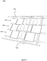
- first row 404 Once the first row 404 is installed, tiles 100 are inserted in the second row 404 as described above with reference to figure 4c .
- the tiles 100 in the second row 404 are aligned with the first row 404 such that the protrusions 118 of the second row tiles 100 align with the holes 116 in the front surface 102 of the first row tiles 100.
- the protrusions 118 near the lower edge 108 of the second row tiles 100 engage with the holes 116 in the upper portion 114 of the front surface 102 of the first row tiles 100, and lock (or at least hold) the lower end 108 of the second row tiles 100 to the upper end 106 of the first row tiles 100 (that is, friction prevents them from easily being lifted by wind).
- Subsequent rows 404 are installed by repeating the sequence described for the second row 404 until the roof 400 is covered by the tiles 100.
- a row of cap tiles (not shown), arranged to fit onto the apex of the roof 400, may be installed to provide a watertight roof 400.
- the tiles 100 may be arranged such that the left and right edges 110, 112 of tiles 100 in the first row 404 are in line with the left and right edges 110, 112 of tiles 100 installed in the second and subsequent rows 404.
- the tiles 100 in the second row 404 may be staggered by half a tile width, as shown in figure 4c .
- a third row 404 it may be staggered by half a tile width with respect to the second row 404, such that the left and right edges 110, 112 of the tiles 100 in the third row 404 are aligned with the left and right edges 110, 112 of the tiles 100 in the first row 404.
- each tile 100 in the main body of the roof is rigidly connected with four other tiles 100, which significantly increases the force required to remove any given tile 100, and thereby improves the resistance of the roof surface to, for example, wind-lift.
- Tiles 100 can be removed by applying a levering force to the lower end 108 of the tile 100 and disengaging the protrusions 118 of a higher placed tile 100 from the holes 116 in the upper end 106 of a lower placed tile 100. The lower end 108 can then be raised to disengage the flange 150 from the tile-holding device 200. Tiles 200 can thereby be removed without damaging the tile 100 and can be reused.
- the back surface 104 of the tile 100 comprises a recess 180 arranged accommodate a fluid cassette that forms part of a solar energy capture system.
- An exemplary fluid cassette 500 is shown in figure 5 . It will however be understood that other configurations of fluid cassette may be fitted to or included in the roof tile 100 of the present invention, which is not limited to the particular configuration of fluid cassette described.
- the fluid cassette 500 has a main reservoir 502, which is a hollow body arranged to contain a volume of fluid.
- the reservoir 502 is substantially cuboid.
- a reservoir inlet port 504 extending from which, away from the reservoir 502, is an inlet pipe 506.
- the inlet pipe 506 extends away from the reservoir inlet port 504 for a distance and then turns via a bend through 90 degrees.
- the end of the inlet pipe 506 terminates with an inlet opening 508.
- a reservoir outlet port 510 extending from which, away from the reservoir 502, is an outlet pipe 512.
- the outlet pipe 512 extends away from the reservoir outlet port 510 for a distance and then turns via a bend through 90 degrees, in an opposite direction to the inlet pipe 506.
- the end of the outlet pipe 512 terminates with an outlet opening 514.
- An external diameter of the outlet opening 514 corresponds approximately with the internal diameter of the inlet opening 508, such that the outlet pipe 512 of one cassette 500 can be connected in series with the inlet pipe 506 of another cassette 500 to provide a push-fit.
- the inlet pipes 506, outlet pipes 512 and reservoirs 502 of the respective cassettes 500 form a fluid path along which fluid can flow through each of the reservoirs 502 and on to the next cassette 500.
- the outlet pipe 512 and/or the inlet pipe 506 may be provided with ribs 515 to increase the seal provided by the push-fit between the inlet and outlet pipes 506, 512.
- the cassette 500 may be made from a plastics material and may be manufactured using, for example, a gas-assisted blow moulding process.
- the cassette 500 may be made from one or more of polypropylene, polyurethane, and HDPE, or from a similar plastics material.
- the cassette 500 may be made from a recycled plastics material.
- the thermal conductivity, coefficient of thermal expansion, resistance to temperature, and mechanical strength of the plastics material, are all considerations affecting the required thickness of the walls of the cassette 500.
- the cassette 500 is made of 3mm thick polyurethane.
- the cassettes 500 are filled with a glycol-based fluid, which can retain heat that is captured from the sun at the front surface 102 of the tile 100 and is transmitted to the back surface 104 of the tile 100 and subsequently to the cassette 500 by thermal conduction.
- the cassette 500 comprises a series of mounting holes 516 passing through the main body of the cassette reservoir 502, that are located to correspond with cassette mounts 182 located in a cassette recess 180 in the back surface 104 of the tile 100.
- the diameter of the mounting holes 516 is arranged such that when engaged with the cassette mounts 182 of the tile 100, the cassette mounts 182 hold the cassette in place by, for example, an interference fit.
- Figure 6 depicts a solar tile 600 comprising a tile 100 with a fluid cassette is mounted in the cassette recess 180.
- the tile 100 is arranged to receive two fluid cassettes 500 arranged side-by-side.
- only one cassette 500 may be received by the tile 100, or higher numbers of cassettes 500 may be received by the tile 100.
- the cassette recess 180 comprises cassette mounts 182.
- the cassette mounts 182 are arranged to engage with corresponding recesses in the cassette to hold the cassette in place in the recess.
- the dimensions of the cassette mounts 182 and the holes 516 may be such that the cassette 500 is held by an interference fit or a compression fit, or the cassette mounts 182 may form a snap fit.
- other mechanisms for fixing the cassette in place such as for example, gluing, or screwing the cassette 500 in place may be employed.
- the inlet pipe 506 of each received cassette 500 is located in the inlet channels 184 and inlet holes 186, and the outlet pipe 512 of each received cassette 500 is located in the outlet channels 188.
- cassette mounts 182 and holes 516 are shown to be cylindrical in shape, it will be understood that any shape, size and extent of mutually corresponding inter-lockable cassette mounts 182 and holes 516 could be used to provide the means to hold the cassette 500 in the cassette recess 180.
- the cassette recess 180, channels 184, 186 and holes 186 enable the tile to receive a cassette 500 capable of gathering solar thermal energy while maintaining the aesthetics of a conventional roof.
- the cassette recess 180, channels 184, 186 and holes 186 enable the exemplary cassettes described above with reference to figure 5 to be interconnected to form a solar thermal energy capture system 700.
- the outlet opening 514 of a cassette 500 fitted to a tile 100 in, for example, the second row 404 is inserted into a corresponding inlet opening 508 in a cassette 500 fitted to a tile 100 in the first row 404 to make a fluidic connection.
- the outlet opening 514 of a cassette 500 fitted to a tile 100 in the third row 404 is inserted into a corresponding inlet opening 508 in a cassette 500 fitted to a tile 100 in the second row 404 to make a fluidic connection, and so on.
- the outlet opening 514 of the cassette 500 fitted to tiles 100 in the first row 404 may be connected to a common drain 702, and the inlet openings 508 of cassettes 500 fitted to tiles 100 in the uppermost row 404 of tiles 100 can be connected to a common fluid supply 704.
- the common fluid supply 704 and common fluid drain 702 can then be connected to a heat exchange system (not shown) having a fluid pump (not shown) to complete a heat exchange circuit.
- the heat exchange circuit may be filled with fluid, such as a glycol-based fluid, which can be pumped by the fluid pump around the heat exchange circuit.
- the common fluid supply 704 may be mounted above the uppermost row 404 of tiles 100 in the roof 400. Fluid is pumped to the common supply 704 by the fluid pump and, because of the serial connections of interconnected cassettes 500 enabled by the configuration of roof tile 100 described, the fluid can then cascade from the highest row 400 of tiles 100, with the assistance of gravity, to successively lower rows 400 of tiles 100. The fluid can then absorb solar thermal energy as it cascades. The fluid can be drained to the common drain 702 from where it can flow to the heat exchanger to exchange the absorbed thermal energy.
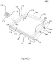
- the cassettes 500 may be fitted to the tiles 100 at the time of manufacture, or may be fitted during installation of the roof 400 as depicted in figure 8.
- Figure 8 shows the cassette 500 being installed in the cassette recess 180 after the flange 150 is inserted into the tile-holding device 200 but before the lower end 108 of the tile 100 is engaged with the upper end 106 of a tile 100 in the row 404 immediately below.
- the protrusions 118 enable the front ends 108 of the tiles 100 to be easily lifted after installation, as described above, it is possible to install the solar thermal cassettes 500 after installation of the roof 400 with relative ease.
- the above embodiments are to be understood as illustrative examples of the invention. Further embodiments of the invention are envisaged.
- the protrusions could instead be located in the upper portion of the front surface of the tile, and corresponding holes be located in the lower recess of the tile.
- the tiles may have different proportions to those described above.
- figure 9 shows a tile 900 is 1.5 times wider that the tile 100 described above.
- the tile 900 may be used in conjunction with standard tiles 100 when installing a roof. By providing both square tiles 100 and tiles 900 that are 1.5 times wider than the square tiles 100 the need to cut the square tiles 100 to fit hips and ridges in the roof and to cover the roof is reduced.
- FIG 10 shows a further embodiment, in which a tile 1000 is 3 times wider than the square tile 100.
- this tile 1000 may be provided with a photovoltaic panel 1002.
- any of the tiles described above could be provided with such a photovoltaic panel.
- FIG. 11a to 12c there are illustrated two variations of the tile 100 illustrated in Figures 1a and 1b .
- Features already described with respect to Figures 1a and 1b are given like reference numerals in Figures 11a to 12c and will not be described in detail again.
- the protrusions 118 are formed during the manufacturing of the tile by the material of the mix used to cast the tile 100.
- a plurality of protrusions 161 each comprising a rigid member 162, in this example a threaded flat headed screw 162, and an elongate compressible member 164.
- Each screw 162 is set in place during the manufacturing process of the tile 100', for example by encasing or moulding the head of a screw within the material of the tile 100' so that the threaded portion of the screw 162 extends from the tile 100' and an elongate compressible member 164 is fixed over the threaded portion to cover the screw 162.
- Each compressible member 164 comprises a tapered anchor portion 165 at its free end.
- each elongate compressible member 164 is a simple plaster board plug and is screwed onto its respective screw 162.
- each of the holes 116 on the upper surface 102 of a tile 100' extends all of the way through the tile 100', so as to form an aperture that is open at both ends.
- a first tile 1100 in a first row may be attached to a second tile 1101 in a second row in a similar fashion as previously described above with reference to the tiles 100 except that in this example a protrusion 161 of the first tile 1100 is pushed through a hole 116 of the second tile 1101 so as to form snap fit connection between the two.
- the flange (not shown in Figure 11b ) of the first tile 1100 is located in a tile-holding device (not shown in Figure 11b ) as previously described and the first tile 1100 is pivoted towards the second tile 1101 so that a protrusion 161 of the first tile 1100 is pushed through a hole 116 of the second tile 1101.
- the protrusion 161 is pushed into the hole 116 contact forces compress the tapered anchor portion 165 causing it to flex inwardly and so reduce its profile or diameter so that the it can freely pass through the hole 116.
- the anchor portion 165 When the anchor portion 165 has passed through the hole 116 and there is no longer a compressive force applied to it, the anchor portion 165 flexes outwardly (e.g. snaps back) to its non-compressed diameter or profile and abuts against the underside of second tile 1101 so that the first 1100 and second 1101 tiles are attached together. In this un-compressed state, the profile or diameter of the anchor portion 165 is larger than the diameter of the hole 116 so the protrusion 161 is resistive to be being pulled back through the hole 116.
- a collar 166 is provided around each hole 116 on the back surface 104 of a tile 100' to provide for better engagement with an anchor portion 165 that has been inserted through the hole 116.
- the tiles 100 in the second (lower) row of tiles 404 may be staggered by, for example, half a tile width with respect to the first (upper) row of tiles 404.
- one protrusion 161 of tile 100 may engage with a hole 116 of a first tile of a lower row of tiles, and the other protrusion 161 of tile 100 may engage with a hole 116 of a second tile of a lower row of tiles.
- the distance between protrusions 161 of a tile 100 needn't necessarily be the same distance as the distance between the holes 116 in the upper portion 114 of the front surface 102 of a tile 100.
- each of the protrusions 168 is a flexible hook 168, for example made of a suitable metal such as aluminium, stainless steel, or copper, or, for example, made of a suitable high density plastic.
- each hook 168 comprises a base section 178, a body section 176 extending substantially perpendicularly from the base section 178 and a hook section 174 extending downwardly from the top of the body section 176.
- a hook 168 may be formed of a single metal strip cut or bent into shape.
- Each hook 168 is set in place during the manufacturing process of the tile, for example, by placing its base section in a recess prior to curing which then encases the base section 178 within the material of the tile 100".
- each flexible hook 168 may be attached to the tile 100" by any suitable fixing means, for example using an adhesive to attach the base section 178 to a tile.
- each slit 170 there are a plurality of slits 170, each extending through the tile 100" so as to form an aperture open at both ends.
- a pair of spaced apart raised portions 172 straddle each slit 170 on the bottom surface 104 of the tile 100".
- a first tile in a first row may be attached to a second tile in a second row in a similar manner as described above with respect to the tile 100', by, as illustrated in the expanded section of Figure 12a , inserting a flexible hook 168 of the first tile through a slit 170 of the second tile to form a snap fit connection between the two.
- the flexible hook 168 As the flexible hook 168 is brought to a slit 170 in the upper portion 114 of the front surface 102 of the second tile so that the plane of the body section 176 is parallel with the plane of the slit 170, the flexible hook 168 is pushed into the slit 170 and, as a result, the hook portion 174 is compressed or flexes against the body section 176, reducing the profile of the flexible hook 168 so that the entire hook portion 174 may pass through the slit 170.
- the hook portion 174 flexes outwardly and so returns (or snaps) to substantially the same configuration as before compression, and hence the snap fit is achieved.
- the hook portion 174 may extend over and abut against a raised portion 172 to provide for a secure engagement.
- the structural specification of the flexible hook 168 (e.g. its thickness and the material from which it is made) may be selected so that the force required to flex the hook portion 174 enough so that the tiles can be detached is sufficiently large that it is unlikely to be achieved in normal use, for example by wind, but may be achieved by a person wishing to remove the tile, for example by hand or using a tool. Similar consideration may be given to the specification of other fixing elements in other exemplary embodiments of the present invention.
- either of the tiles 100' and 100" may be adapted to comprise a fluid cassette (not shown) that forms part of a solar energy capture system as described previously with respect to the tile 100.
Landscapes
- Engineering & Computer Science (AREA)
- Architecture (AREA)
- Civil Engineering (AREA)
- Structural Engineering (AREA)
- Mechanical Engineering (AREA)
- Life Sciences & Earth Sciences (AREA)
- Physics & Mathematics (AREA)
- Sustainable Development (AREA)
- Sustainable Energy (AREA)
- Thermal Sciences (AREA)
- Chemical & Material Sciences (AREA)
- Combustion & Propulsion (AREA)
- General Engineering & Computer Science (AREA)
- Roof Covering Using Slabs Or Stiff Sheets (AREA)
Claims (15)
- Dachziegelsystem, umfassend:einen ersten Dachziegel (100) und einen zweiten Dachziegel (100), wobei der erste und zweite Dachziegel (100) jeweils umfassen:ein erstes Befestigungsmittel, wobei das erste Befestigungsmittel zum Befestigen des ersten Dachziegels (100) mit einem zweiten Dachziegel (100) dient, wenn der erste Dachziegel (100) und der zweite Dachziegel (100) zusammen auf einem Dach angeordnet sind; undeinen Flansch (150), der sich von einem ersten Endabschnitt des entsprechenden ersten und zweiten Dachziegels (100) erstreckt, wobei der Flansch (150) eine obere Oberfläche und eine untere Oberfläche aufweist, wobei, so wie der Flansch (150) sich erstreckt, das Profil der oberen Oberfläche in einem flachen Winkel bis zu einer Spitze zunimmt und dann stark abfällt, um eine tiefe Aussparung (158) zu bilden, und dann wieder bis zum oberen Ende des Dachziegels (100) ansteigt; undeine Ziegelhalterung (200) zum Befestigen mit dem Dach, wobei die Ziegelhalterung (200) einen Basisabschnitt (202), einen Rückabschnitt (204) und einen Eingriffsabschnitt (206) umfasst, wobei der Basisabschnitt (202) und der Eingriffsabschnitt (206) sich von der gleichen Seite jedes Endes des Rückabschnitts (204) in im Wesentlichen senkrechten Winkel erstrecken, wobei, so wie sich der Eingriffsabschnitt (206) erstreckt, er in Richtung auf den Basisabschnitt (202) gebogen ist, wobei die Biegung einen oberen Bogen bildet und einen Kanal zwischen dem Eingriffsabschnitt (206) und dem Basisabschnitt (202) definiert,wobei die Ziegelhalterung (200) eingerichtet ist, Bewegungen des ersten Dachziegels (100) mit seinem Flansch (150) in Eingriff mit der Halterung (200) von einer ersten Orientierung in eine zweite Orientierung durch eine Schwenkbewegung um den Flansch (150) zu ermöglichen, und der Grad der Krümmung des oberen Bogens dem Eingriffsflansch (150) ermöglicht, zwischen den Eingriffsabschnitt (206) und den Basisabschnitt (202) eingefügt zu werden, wenn die Ebene des Ziegels (100) in der ersten Orientierung, bezogen auf die Ebene des Basisabschnitts (202), orientiert ist, und die tiefe Aussparung (158) mit dem Eingriffsabschnitt (206) in Eingriff bringbar ist, um ein Einfügen oder Entfernen des Flansches (150) zu verhindern, wenn der erste Dachziegel (100) in der zweiten Orientierung ist, um das Anheben des ersten Endabschnitts des ersten Dachziegels (100) vom Dach zu verhindern.
- Dachziegelsystem nach Anspruch 1, umfassend, an oder in Richtung auf den ersten Endabschnitt, ein zweites Befestigungsmittel, das eingerichtet ist, den ersten Dachziegel an einem dritten Dachziegel zu befestigen, wenn der erste Dachziegel und der dritte Dachziegel zusammen auf einem Dach angeordnet sind.
- Dachziegelsystem nach Anspruch 1 oder 2, wobei das erste Befestigungsmittel mindestens eine erste Formation zum Eingreifen in mindestens eine Formation des zweiten Dachziegels umfasst.
- Dachziegelsystem nach Anspruch 2, wobei das zweite Befestigungsmittel mindestens eine zweite Formation zum Eingreifen in mindestens eine Formation des dritten Dachziegels umfasst, wenn der erste Dachziegel und der dritte Dachziegel zusammen auf einem Dach angeordnet sind.
- Dachziegelsystem nach einem der vorhergehenden Ansprüche, wobei mindestens einer der ersten und zweiten Endabschnitte des ersten und zweiten Dachziegels (100) einen ausgesparten Abschnitt umfasst, der sich entlang mindestens eines Teils des jeweiligen Endabschnitts erstreckt.
- Dachziegelsystem nach einem der vorhergehenden Ansprüche, wobei der erste und zweite Dachziegel (100) aus einer Matrix aus Schiefergranulat gebildet sind, die durch ein Harz gebunden ist, und der Vorsprung des ersten und zweiten Dachziegels (100) in das Harz eingebettet ist.
- Dachziegelsystem nach Anspruch 2, wobei eines von dem ersten Befestigungsmittel und dem zweiten Befestigungsmittel mindestens einen Vorsprung umfasst, der sich von dem ersten Ziegel erstreckt, und das andere von dem ersten Befestigungsmittel und zweiten Befestigungsmittel einen Empfangsabschnitt umfasst, wobei der mindestens eine Vorsprung in dem Empfangsabschnitt von einem von dem zweiten Dachziegel und dem dritten Dachziegel empfangbar ist, und wobei der mindestens eine Empfangsabschnitt des ersten Ziegels zum Empfangen eines Vorsprungs des anderen von dem zweiten Dachziegel und dem dritten Dachziegel ist.
- Dachziegelsystem nach einem der Ansprüche 2 bis 7, wobei der erste Dachziegel (100) einen erhöhten Abschnitt (172), angrenzend an die Öffnung (170) auf der zweiten Seite des ersten Dachziegels (100), aufweist und über der ein Ankerabschnitt eines Vorsprungs (118, 161, 168) des anderen von dem zweiten Dachziegel und dem dritten Dachziegel (100) einhaken kann, wenn ein Vorsprung (118, 161, 168) des anderen von dem zweiten Dachziegel und dem dritten Dachziegel (100) in der Öffnung empfangen wird.
- Dachziegelsystem nach einem der vorhergehenden Ansprüche, wobei der erste Endabschnitt des ersten Dachziegels (100) einen ausgesparten Abschnitt umfasst und das erste Befestigungsmittel in dem ausgesparten Abschnitt angeordnet ist.
- Dachziegelsystem nach einem der vorhergehenden Ansprüche, wobei der erste Dachziegel (100) eine erste Oberfläche aufweist, die bei der Verwendung sichtbar ist, und eine zweite Oberfläche, die einen Kassettenvertiefungsabschnitt (180) aufweist, der eingerichtet ist, eine Kassette zum Beinhalten eines zu beheizenden Fluids aufzunehmen.
- Dachziegelsystem nach einem der vorhergehenden Ansprüche, umfassend, in der zweiten Oberfläche, Kanäle, die eingerichtet sind, Fluidverbindungen, die in der Kassette angeordnet sind, aufzunehmen, wobei die Kanäle zumindest einen Einlasskanal umfassen, der eingerichtet ist, eine Einlassfluidverbindung der Kassette aufzunehmen und mindestens einen Auslasskanal, der eingerichtet ist, eine Auslassfluidverbindung der Kassette aufzunehmen, wobei zumindest ein Teil des Eingangskanals sich von der zweiten Oberfläche zur ersten Oberfläche der ersten Dachziegel (100) erstreckt.
- Dachziegelsystem nach einem der vorhergehenden Ansprüche, wobei der erste Dachziegel (100) eine erste Kante und eine zweite Kante umfasst, wobei die erste Kante mindestens einen Grat aufweist, der sich entlang der ersten Kante auf der ersten Oberfläche erstreckt, und die zweite Kante mindestens ein Tal umfasst, das mit dem Grat korrespondiert, wobei das Tal sich entlang der zweiten Kante auf einer zweiten Oberfläche erstreckt, wobei die Tiefe des mindestens einen Tals von einer ersten Tiefe am ersten Endabschnitt bis zu einer zweiten Tiefe beim zweiten Endabschnitt variiert, wobei die erste Tiefe größer als die zweite Tiefe ist.
- Dachziegelsystem nach einem der vorhergehenden Ansprüche, wobei der Flansch des ersten Dachziegels (100) einen Kanal aufweist, der eingerichtet ist, Wasser zu einer Kante des Ziegels zu tragen.
- Dachziegelsystem nach einem der vorhergehenden Ansprüche, umfassend mehrere Dachziegel (100), wobei mindestens einige der Dachziegel (100) eine Kassette umfassen, und jede Kassette fluidisch mit mindestens einer anderen Kassette verbunden ist, wobei der Auslass von mindestens einer Kassette fluidisch mit dem Einlass einer benachbarten Kassette verbunden ist, sodass Fluid von der mindestens einen Kassette zur benachbarten Kassette übergehen kann.
- Verfahren zum Installieren eines Dachziegelsystems nach einem der vorhergehenden Ansprüche, wobei das Verfahren umfasst:Befestigen der Ziegelhalterung (200) auf einem Dach;Bringen des Flansches (150) des ersten Ziegels (100) in einer ersten Orientierung in Eingriff mit dem Kanal der Ziegelhalterung (200);Bewegen, durch eine Schwenkbewegung um den Flansch (150), des ersten Ziegels (100) von einer ersten Orientierung, bei der der Grad einer Krümmung des oberen Bogens dem Eingriffsflansch (150) ermöglicht, zwischen den Eingriffsabschnitt (206) und den Basisabschnitt (202) einzugreifen, in eine zweite Orientierung, in der der Grad der Krümmung des oberen Bogens ein Einfügen oder Entfernen des Flanschs (150) verhindert.
Applications Claiming Priority (2)
| Application Number | Priority Date | Filing Date | Title |
|---|---|---|---|
| GB1303111.7A GB2511070A (en) | 2013-02-21 | 2013-02-21 | Roof tile system |
| PCT/EP2014/053266 WO2014128183A1 (en) | 2013-02-21 | 2014-02-19 | Roof tile system |
Publications (2)
| Publication Number | Publication Date |
|---|---|
| EP2959072A1 EP2959072A1 (de) | 2015-12-30 |
| EP2959072B1 true EP2959072B1 (de) | 2019-10-09 |
Family
ID=48091891
Family Applications (1)
| Application Number | Title | Priority Date | Filing Date |
|---|---|---|---|
| EP14709570.7A Active EP2959072B1 (de) | 2013-02-21 | 2014-02-19 | Dachziegelsystem |
Country Status (4)
| Country | Link |
|---|---|
| US (1) | US10280624B2 (de) |
| EP (1) | EP2959072B1 (de) |
| GB (1) | GB2511070A (de) |
| WO (1) | WO2014128183A1 (de) |
Families Citing this family (20)
| Publication number | Priority date | Publication date | Assignee | Title |
|---|---|---|---|---|
| KR102419365B1 (ko) * | 2014-08-29 | 2022-07-11 | 유한회사 중앙강재 | 융설 기와 및 이를 포함하는 지붕 융설 시스템 |
| US10756669B2 (en) | 2014-12-04 | 2020-08-25 | Solarmass Energy Group Ltd. | Solar roof tile |
| CA3001144C (en) | 2015-10-06 | 2022-04-12 | Trac Group Holdings Ltd | Solar thermal collector |
| CN106760234A (zh) * | 2016-08-10 | 2017-05-31 | 周柯 | 一种新型屋面瓦固定构件 |
| US10508448B2 (en) | 2017-09-11 | 2019-12-17 | Lala Khajani | Tile and method of production |
| CN108954864B (zh) * | 2018-05-29 | 2020-04-28 | 西安航天神舟建筑设计院有限公司 | 砖瓦式太阳热能收集器 |
| US11384542B2 (en) * | 2019-03-28 | 2022-07-12 | Ply Gem Industries, Inc. | Roof shingle tile and method of installing the same |
| US10530292B1 (en) * | 2019-04-02 | 2020-01-07 | Solarmass Energy Group Ltd. | Solar roof tile with integrated cable management system |
| CA3151068A1 (en) * | 2019-09-16 | 2021-03-25 | John Humphreys | Method and apparatus for installing roofing shingles |
| FR3102196B1 (fr) * | 2019-10-18 | 2021-12-17 | Onduline Sa | Tuile photovoltaïque plate, procédé de pose et couverture obtenue |
| US11933049B1 (en) | 2020-05-07 | 2024-03-19 | Jason McSpadden Woodland | Roofing system |
| US12395116B2 (en) * | 2020-08-24 | 2025-08-19 | Colin Felton | Labor saving solar roofing shingle |
| GB2599921A (en) * | 2020-10-14 | 2022-04-20 | Hambleside Danelaw Ltd | A system for covering a roof and a mounting unit therefor |
| GB2600396B8 (en) * | 2020-10-21 | 2024-05-15 | Patterson And Rothwell Ltd | A roof tile |
| US12421732B2 (en) * | 2020-11-13 | 2025-09-23 | Certainteed Llc | Flat siding panel and panel siding system |
| NL2027258B1 (en) * | 2020-12-31 | 2022-07-21 | Exa Ip Bv | Integrated photovoltaic roof element |
| WO2023275629A1 (en) * | 2021-06-29 | 2023-01-05 | Arka Energy Inc. | System for mounting tiles over a surface |
| CN113530095B (zh) * | 2021-07-03 | 2022-09-02 | 广东中城建设集团有限公司 | 一种大坡度斜屋面瓦固定结构 |
| CN116065762A (zh) * | 2022-10-26 | 2023-05-05 | 天合光能股份有限公司 | 光伏瓦及具有坡度的光伏屋顶 |
| US12540474B2 (en) * | 2024-07-22 | 2026-02-03 | GAF Energy LLC | Electrically grounding metal roofing shingles with photovoltaic systems |
Citations (2)
| Publication number | Priority date | Publication date | Assignee | Title |
|---|---|---|---|---|
| US6052961A (en) * | 1996-07-30 | 2000-04-25 | Gibbs; Alden T. | Roof mounting assembly |
| EP2304122A1 (de) * | 2008-07-29 | 2011-04-06 | Green IP Box Limited | Vernetzbare ziegel |
Family Cites Families (17)
| Publication number | Priority date | Publication date | Assignee | Title |
|---|---|---|---|---|
| DE1166993B (de) * | 1960-04-25 | 1964-04-02 | Richard Kellerhoff | Dachlatte mit etwa C-foermigem Querschnitt |
| US4210122A (en) * | 1976-08-11 | 1980-07-01 | Artweger-Industrie-Gesellschaft M.B.H. | Energy conversion apparatus |
| GB2123050B (en) * | 1982-06-25 | 1986-01-29 | Marley Roof Tile | Roof ridge capping system |
| GB2202245A (en) * | 1987-03-18 | 1988-09-21 | Fastile | Tiling |
| AU1367392A (en) * | 1991-03-13 | 1992-10-21 | Philip David Sebastian Bainbridge | Cladding system for solar tiles |
| US5164020A (en) * | 1991-05-24 | 1992-11-17 | Solarex Corporation | Solar panel |
| ES2264988T3 (es) * | 2000-10-09 | 2007-02-01 | Peter Martin Broatch | Tejado termico solar. |
| JP2002317527A (ja) * | 2001-04-19 | 2002-10-31 | Minebea Co Ltd | 瓦及びそれを用いた融雪屋根 |
| US7748191B2 (en) * | 2001-04-26 | 2010-07-06 | B-Pods Holdings Pty Ltd. | Cladding apparatus and methods |
| WO2002090839A1 (en) * | 2001-05-08 | 2002-11-14 | Aljosa Pajk | Modular system for utilization of solar energy for heating of sanitary water |
| ITBZ20060033A1 (it) * | 2006-07-28 | 2008-01-29 | Alberto Volcan | Pannello solare, in particolare tegola. |
| AT505553B1 (de) * | 2007-08-02 | 2009-02-15 | Deutsch Wolfgang | Dachziegel |
| AT506959B1 (de) * | 2008-07-29 | 2010-01-15 | Deutsch Wolfgang | Dachziegel |
| GB2473447B (en) * | 2009-09-09 | 2011-09-21 | Meirion Gribble | Tile and tile holding device |
| GB0916384D0 (en) | 2009-09-18 | 2009-10-28 | Vale Mill Rochdale Ltd | Ironing board |
| NZ592562A (en) * | 2011-04-29 | 2013-11-29 | Edward Lawrence Noton | An Improved Roof Tile |
| DE102013006332A1 (de) * | 2013-04-12 | 2014-10-16 | Fraunhofer-Gesellschaft zur Förderung der angewandten Forschung e.V. | Solarmodulträger für die Belegung von schrägen Objektflächen mit homogener Flächenbedeckung |
-
2013
- 2013-02-21 GB GB1303111.7A patent/GB2511070A/en not_active Withdrawn
-
2014
- 2014-02-19 WO PCT/EP2014/053266 patent/WO2014128183A1/en not_active Ceased
- 2014-02-19 EP EP14709570.7A patent/EP2959072B1/de active Active
-
2015
- 2015-08-18 US US14/829,528 patent/US10280624B2/en active Active
Patent Citations (2)
| Publication number | Priority date | Publication date | Assignee | Title |
|---|---|---|---|---|
| US6052961A (en) * | 1996-07-30 | 2000-04-25 | Gibbs; Alden T. | Roof mounting assembly |
| EP2304122A1 (de) * | 2008-07-29 | 2011-04-06 | Green IP Box Limited | Vernetzbare ziegel |
Also Published As
| Publication number | Publication date |
|---|---|
| US10280624B2 (en) | 2019-05-07 |
| EP2959072A1 (de) | 2015-12-30 |
| GB201303111D0 (en) | 2013-04-10 |
| WO2014128183A1 (en) | 2014-08-28 |
| GB2511070A (en) | 2014-08-27 |
| US20150354217A1 (en) | 2015-12-10 |
Similar Documents
| Publication | Publication Date | Title |
|---|---|---|
| EP2959072B1 (de) | Dachziegelsystem | |
| EP2729638B1 (de) | Befestigungssystem | |
| DK2784241T3 (en) | Roofing for solar energy utilization | |
| EP3227507B1 (de) | Dachdeck-, verkleidungs- oder aussenverkleidungsvorrichtung | |
| US6212837B1 (en) | Rain water diverter system for deck structures | |
| WO2010128375A2 (en) | Profiled joint for connecting solar panels | |
| CN108291741B (zh) | 太阳能集热器 | |
| JP5396109B2 (ja) | 屋根上パネル設置用屋根瓦及び屋根上パネルの設置方法 | |
| EP3319228B1 (de) | Integriertes solarpaneel auf einem ziegeldach | |
| US20100308181A1 (en) | Pipe support base | |
| KR20120008812A (ko) | 건축물 내외장용 금속패널 및 시공방법 | |
| US20250253632A1 (en) | Exterior junction boxes | |
| CN217268411U (zh) | 一种节能环保型女儿墙防渗水结构 | |
| JP2005268260A (ja) | 太陽光発電システム | |
| JP7212406B2 (ja) | 表層部分が水下側へ延出する突出部を備える断熱材を用いる横葺き外装材 | |
| US20110078972A1 (en) | Siding Installation Spacer and Method of Installing Siding Using A Siding Installation Spacer | |
| EP2738822A1 (de) | Montagesystem zur Installation von Paneelen, beispielsweise von photovoltaischen Paneelen, an einem Gebäude | |
| JP5601923B2 (ja) | 屋根外設材の取付方法 | |
| JP2929458B2 (ja) | 屋根材及びその施工法 | |
| EP3172388B1 (de) | Halteklammer für ein bedachungssystem mit windsogschutz | |
| JP2005240387A (ja) | 太陽光発電システム | |
| JP6116057B2 (ja) | 屋根構造 | |
| CA3264011A1 (en) | Exterior junction boxes | |
| JP2005281996A (ja) | 太陽光発電システム | |
| JP2020117915A (ja) | 外設部材の取付構造、及びその施工方法 |
Legal Events
| Date | Code | Title | Description |
|---|---|---|---|
| PUAI | Public reference made under article 153(3) epc to a published international application that has entered the european phase |
Free format text: ORIGINAL CODE: 0009012 |
|
| 17P | Request for examination filed |
Effective date: 20150921 |
|
| AK | Designated contracting states |
Kind code of ref document: A1 Designated state(s): AL AT BE BG CH CY CZ DE DK EE ES FI FR GB GR HR HU IE IS IT LI LT LU LV MC MK MT NL NO PL PT RO RS SE SI SK SM TR |
|
| AX | Request for extension of the european patent |
Extension state: BA ME |
|
| DAX | Request for extension of the european patent (deleted) | ||
| STAA | Information on the status of an ep patent application or granted ep patent |
Free format text: STATUS: EXAMINATION IS IN PROGRESS |
|
| 17Q | First examination report despatched |
Effective date: 20161221 |
|
| GRAP | Despatch of communication of intention to grant a patent |
Free format text: ORIGINAL CODE: EPIDOSNIGR1 |
|
| STAA | Information on the status of an ep patent application or granted ep patent |
Free format text: STATUS: GRANT OF PATENT IS INTENDED |
|
| RIC1 | Information provided on ipc code assigned before grant |
Ipc: E04D 12/00 20060101ALI20190212BHEP Ipc: E04D 1/30 20060101AFI20190212BHEP Ipc: F24S 20/69 20180101ALI20190212BHEP Ipc: E04D 13/00 20060101ALI20190212BHEP Ipc: E04D 1/12 20060101ALI20190212BHEP Ipc: E04D 1/34 20060101ALI20190212BHEP |
|
| INTG | Intention to grant announced |
Effective date: 20190301 |
|
| GRAS | Grant fee paid |
Free format text: ORIGINAL CODE: EPIDOSNIGR3 |
|
| GRAA | (expected) grant |
Free format text: ORIGINAL CODE: 0009210 |
|
| STAA | Information on the status of an ep patent application or granted ep patent |
Free format text: STATUS: THE PATENT HAS BEEN GRANTED |
|
| AK | Designated contracting states |
Kind code of ref document: B1 Designated state(s): AL AT BE BG CH CY CZ DE DK EE ES FI FR GB GR HR HU IE IS IT LI LT LU LV MC MK MT NL NO PL PT RO RS SE SI SK SM TR |
|
| REG | Reference to a national code |
Ref country code: GB Ref legal event code: FG4D |
|
| REG | Reference to a national code |
Ref country code: CH Ref legal event code: EP |
|
| REG | Reference to a national code |
Ref country code: IE Ref legal event code: FG4D |
|
| REG | Reference to a national code |
Ref country code: DE Ref legal event code: R096 Ref document number: 602014054846 Country of ref document: DE |
|
| REG | Reference to a national code |
Ref country code: AT Ref legal event code: REF Ref document number: 1188971 Country of ref document: AT Kind code of ref document: T Effective date: 20191115 |
|
| REG | Reference to a national code |
Ref country code: NL Ref legal event code: MP Effective date: 20191009 |
|
| REG | Reference to a national code |
Ref country code: LT Ref legal event code: MG4D |
|
| REG | Reference to a national code |
Ref country code: AT Ref legal event code: MK05 Ref document number: 1188971 Country of ref document: AT Kind code of ref document: T Effective date: 20191009 |
|
| PG25 | Lapsed in a contracting state [announced via postgrant information from national office to epo] |
Ref country code: PT Free format text: LAPSE BECAUSE OF FAILURE TO SUBMIT A TRANSLATION OF THE DESCRIPTION OR TO PAY THE FEE WITHIN THE PRESCRIBED TIME-LIMIT Effective date: 20200210 Ref country code: SE Free format text: LAPSE BECAUSE OF FAILURE TO SUBMIT A TRANSLATION OF THE DESCRIPTION OR TO PAY THE FEE WITHIN THE PRESCRIBED TIME-LIMIT Effective date: 20191009 Ref country code: AT Free format text: LAPSE BECAUSE OF FAILURE TO SUBMIT A TRANSLATION OF THE DESCRIPTION OR TO PAY THE FEE WITHIN THE PRESCRIBED TIME-LIMIT Effective date: 20191009 Ref country code: LV Free format text: LAPSE BECAUSE OF FAILURE TO SUBMIT A TRANSLATION OF THE DESCRIPTION OR TO PAY THE FEE WITHIN THE PRESCRIBED TIME-LIMIT Effective date: 20191009 Ref country code: GR Free format text: LAPSE BECAUSE OF FAILURE TO SUBMIT A TRANSLATION OF THE DESCRIPTION OR TO PAY THE FEE WITHIN THE PRESCRIBED TIME-LIMIT Effective date: 20200110 Ref country code: BG Free format text: LAPSE BECAUSE OF FAILURE TO SUBMIT A TRANSLATION OF THE DESCRIPTION OR TO PAY THE FEE WITHIN THE PRESCRIBED TIME-LIMIT Effective date: 20200109 Ref country code: FI Free format text: LAPSE BECAUSE OF FAILURE TO SUBMIT A TRANSLATION OF THE DESCRIPTION OR TO PAY THE FEE WITHIN THE PRESCRIBED TIME-LIMIT Effective date: 20191009 Ref country code: NO Free format text: LAPSE BECAUSE OF FAILURE TO SUBMIT A TRANSLATION OF THE DESCRIPTION OR TO PAY THE FEE WITHIN THE PRESCRIBED TIME-LIMIT Effective date: 20200109 Ref country code: LT Free format text: LAPSE BECAUSE OF FAILURE TO SUBMIT A TRANSLATION OF THE DESCRIPTION OR TO PAY THE FEE WITHIN THE PRESCRIBED TIME-LIMIT Effective date: 20191009 Ref country code: PL Free format text: LAPSE BECAUSE OF FAILURE TO SUBMIT A TRANSLATION OF THE DESCRIPTION OR TO PAY THE FEE WITHIN THE PRESCRIBED TIME-LIMIT Effective date: 20191009 Ref country code: NL Free format text: LAPSE BECAUSE OF FAILURE TO SUBMIT A TRANSLATION OF THE DESCRIPTION OR TO PAY THE FEE WITHIN THE PRESCRIBED TIME-LIMIT Effective date: 20191009 Ref country code: ES Free format text: LAPSE BECAUSE OF FAILURE TO SUBMIT A TRANSLATION OF THE DESCRIPTION OR TO PAY THE FEE WITHIN THE PRESCRIBED TIME-LIMIT Effective date: 20191009 |
|
| PG25 | Lapsed in a contracting state [announced via postgrant information from national office to epo] |
Ref country code: RS Free format text: LAPSE BECAUSE OF FAILURE TO SUBMIT A TRANSLATION OF THE DESCRIPTION OR TO PAY THE FEE WITHIN THE PRESCRIBED TIME-LIMIT Effective date: 20191009 Ref country code: HR Free format text: LAPSE BECAUSE OF FAILURE TO SUBMIT A TRANSLATION OF THE DESCRIPTION OR TO PAY THE FEE WITHIN THE PRESCRIBED TIME-LIMIT Effective date: 20191009 Ref country code: IS Free format text: LAPSE BECAUSE OF FAILURE TO SUBMIT A TRANSLATION OF THE DESCRIPTION OR TO PAY THE FEE WITHIN THE PRESCRIBED TIME-LIMIT Effective date: 20200224 |
|
| PG25 | Lapsed in a contracting state [announced via postgrant information from national office to epo] |
Ref country code: AL Free format text: LAPSE BECAUSE OF FAILURE TO SUBMIT A TRANSLATION OF THE DESCRIPTION OR TO PAY THE FEE WITHIN THE PRESCRIBED TIME-LIMIT Effective date: 20191009 |
|
| REG | Reference to a national code |
Ref country code: DE Ref legal event code: R097 Ref document number: 602014054846 Country of ref document: DE |
|
| PG2D | Information on lapse in contracting state deleted |
Ref country code: IS |
|
| PG25 | Lapsed in a contracting state [announced via postgrant information from national office to epo] |
Ref country code: RO Free format text: LAPSE BECAUSE OF FAILURE TO SUBMIT A TRANSLATION OF THE DESCRIPTION OR TO PAY THE FEE WITHIN THE PRESCRIBED TIME-LIMIT Effective date: 20191009 Ref country code: CZ Free format text: LAPSE BECAUSE OF FAILURE TO SUBMIT A TRANSLATION OF THE DESCRIPTION OR TO PAY THE FEE WITHIN THE PRESCRIBED TIME-LIMIT Effective date: 20191009 Ref country code: DK Free format text: LAPSE BECAUSE OF FAILURE TO SUBMIT A TRANSLATION OF THE DESCRIPTION OR TO PAY THE FEE WITHIN THE PRESCRIBED TIME-LIMIT Effective date: 20191009 Ref country code: EE Free format text: LAPSE BECAUSE OF FAILURE TO SUBMIT A TRANSLATION OF THE DESCRIPTION OR TO PAY THE FEE WITHIN THE PRESCRIBED TIME-LIMIT Effective date: 20191009 Ref country code: IS Free format text: LAPSE BECAUSE OF FAILURE TO SUBMIT A TRANSLATION OF THE DESCRIPTION OR TO PAY THE FEE WITHIN THE PRESCRIBED TIME-LIMIT Effective date: 20200209 |
|
| PLBE | No opposition filed within time limit |
Free format text: ORIGINAL CODE: 0009261 |
|
| STAA | Information on the status of an ep patent application or granted ep patent |
Free format text: STATUS: NO OPPOSITION FILED WITHIN TIME LIMIT |
|
| PG25 | Lapsed in a contracting state [announced via postgrant information from national office to epo] |
Ref country code: SK Free format text: LAPSE BECAUSE OF FAILURE TO SUBMIT A TRANSLATION OF THE DESCRIPTION OR TO PAY THE FEE WITHIN THE PRESCRIBED TIME-LIMIT Effective date: 20191009 Ref country code: SM Free format text: LAPSE BECAUSE OF FAILURE TO SUBMIT A TRANSLATION OF THE DESCRIPTION OR TO PAY THE FEE WITHIN THE PRESCRIBED TIME-LIMIT Effective date: 20191009 Ref country code: IT Free format text: LAPSE BECAUSE OF FAILURE TO SUBMIT A TRANSLATION OF THE DESCRIPTION OR TO PAY THE FEE WITHIN THE PRESCRIBED TIME-LIMIT Effective date: 20191009 |
|
| 26N | No opposition filed |
Effective date: 20200710 |
|
| REG | Reference to a national code |
Ref country code: CH Ref legal event code: PL |
|
| PG25 | Lapsed in a contracting state [announced via postgrant information from national office to epo] |
Ref country code: MC Free format text: LAPSE BECAUSE OF FAILURE TO SUBMIT A TRANSLATION OF THE DESCRIPTION OR TO PAY THE FEE WITHIN THE PRESCRIBED TIME-LIMIT Effective date: 20191009 Ref country code: LU Free format text: LAPSE BECAUSE OF NON-PAYMENT OF DUE FEES Effective date: 20200219 |
|
| PGFP | Annual fee paid to national office [announced via postgrant information from national office to epo] |
Ref country code: IE Payment date: 20200826 Year of fee payment: 7 Ref country code: FR Payment date: 20200824 Year of fee payment: 7 Ref country code: DE Payment date: 20200827 Year of fee payment: 7 |
|
| PG25 | Lapsed in a contracting state [announced via postgrant information from national office to epo] |
Ref country code: SI Free format text: LAPSE BECAUSE OF FAILURE TO SUBMIT A TRANSLATION OF THE DESCRIPTION OR TO PAY THE FEE WITHIN THE PRESCRIBED TIME-LIMIT Effective date: 20191009 Ref country code: LI Free format text: LAPSE BECAUSE OF NON-PAYMENT OF DUE FEES Effective date: 20200229 Ref country code: CH Free format text: LAPSE BECAUSE OF NON-PAYMENT OF DUE FEES Effective date: 20200229 |
|
| PGFP | Annual fee paid to national office [announced via postgrant information from national office to epo] |
Ref country code: BE Payment date: 20200825 Year of fee payment: 7 |
|
| REG | Reference to a national code |
Ref country code: DE Ref legal event code: R119 Ref document number: 602014054846 Country of ref document: DE |
|
| REG | Reference to a national code |
Ref country code: BE Ref legal event code: MM Effective date: 20210228 |
|
| PG25 | Lapsed in a contracting state [announced via postgrant information from national office to epo] |
Ref country code: IE Free format text: LAPSE BECAUSE OF NON-PAYMENT OF DUE FEES Effective date: 20210219 Ref country code: FR Free format text: LAPSE BECAUSE OF NON-PAYMENT OF DUE FEES Effective date: 20210228 Ref country code: DE Free format text: LAPSE BECAUSE OF NON-PAYMENT OF DUE FEES Effective date: 20210901 |
|
| PG25 | Lapsed in a contracting state [announced via postgrant information from national office to epo] |
Ref country code: TR Free format text: LAPSE BECAUSE OF FAILURE TO SUBMIT A TRANSLATION OF THE DESCRIPTION OR TO PAY THE FEE WITHIN THE PRESCRIBED TIME-LIMIT Effective date: 20191009 Ref country code: MT Free format text: LAPSE BECAUSE OF FAILURE TO SUBMIT A TRANSLATION OF THE DESCRIPTION OR TO PAY THE FEE WITHIN THE PRESCRIBED TIME-LIMIT Effective date: 20191009 Ref country code: CY Free format text: LAPSE BECAUSE OF FAILURE TO SUBMIT A TRANSLATION OF THE DESCRIPTION OR TO PAY THE FEE WITHIN THE PRESCRIBED TIME-LIMIT Effective date: 20191009 |
|
| PG25 | Lapsed in a contracting state [announced via postgrant information from national office to epo] |
Ref country code: MK Free format text: LAPSE BECAUSE OF FAILURE TO SUBMIT A TRANSLATION OF THE DESCRIPTION OR TO PAY THE FEE WITHIN THE PRESCRIBED TIME-LIMIT Effective date: 20191009 |
|
| PG25 | Lapsed in a contracting state [announced via postgrant information from national office to epo] |
Ref country code: BE Free format text: LAPSE BECAUSE OF NON-PAYMENT OF DUE FEES Effective date: 20210228 |
|
| PGFP | Annual fee paid to national office [announced via postgrant information from national office to epo] |
Ref country code: GB Payment date: 20250829 Year of fee payment: 12 |