EP2957705B1 - Actionneur électromécanique et installation domotique comprenant un tel actionneur - Google Patents
Actionneur électromécanique et installation domotique comprenant un tel actionneur Download PDFInfo
- Publication number
- EP2957705B1 EP2957705B1 EP15172240.2A EP15172240A EP2957705B1 EP 2957705 B1 EP2957705 B1 EP 2957705B1 EP 15172240 A EP15172240 A EP 15172240A EP 2957705 B1 EP2957705 B1 EP 2957705B1
- Authority
- EP
- European Patent Office
- Prior art keywords
- drum
- housing
- input member
- ring
- electromechanical actuator
- Prior art date
- Legal status (The legal status is an assumption and is not a legal conclusion. Google has not performed a legal analysis and makes no representation as to the accuracy of the status listed.)
- Active
Links
Images


Classifications
-
- H—ELECTRICITY
- H02—GENERATION; CONVERSION OR DISTRIBUTION OF ELECTRIC POWER
- H02K—DYNAMO-ELECTRIC MACHINES
- H02K7/00—Arrangements for handling mechanical energy structurally associated with dynamo-electric machines, e.g. structural association with mechanical driving motors or auxiliary dynamo-electric machines
- H02K7/10—Structural association with clutches, brakes, gears, pulleys or mechanical starters
- H02K7/102—Structural association with clutches, brakes, gears, pulleys or mechanical starters with friction brakes
-
- E—FIXED CONSTRUCTIONS
- E06—DOORS, WINDOWS, SHUTTERS, OR ROLLER BLINDS IN GENERAL; LADDERS
- E06B—FIXED OR MOVABLE CLOSURES FOR OPENINGS IN BUILDINGS, VEHICLES, FENCES OR LIKE ENCLOSURES IN GENERAL, e.g. DOORS, WINDOWS, BLINDS, GATES
- E06B9/00—Screening or protective devices for wall or similar openings, with or without operating or securing mechanisms; Closures of similar construction
- E06B9/24—Screens or other constructions affording protection against light, especially against sunshine; Similar screens for privacy or appearance; Slat blinds
- E06B9/26—Lamellar or like blinds, e.g. venetian blinds
- E06B9/28—Lamellar or like blinds, e.g. venetian blinds with horizontal lamellae, e.g. non-liftable
- E06B9/30—Lamellar or like blinds, e.g. venetian blinds with horizontal lamellae, e.g. non-liftable liftable
- E06B9/32—Operating, guiding, or securing devices therefor
- E06B9/322—Details of operating devices, e.g. pulleys, brakes, spring drums, drives
-
- E—FIXED CONSTRUCTIONS
- E06—DOORS, WINDOWS, SHUTTERS, OR ROLLER BLINDS IN GENERAL; LADDERS
- E06B—FIXED OR MOVABLE CLOSURES FOR OPENINGS IN BUILDINGS, VEHICLES, FENCES OR LIKE ENCLOSURES IN GENERAL, e.g. DOORS, WINDOWS, BLINDS, GATES
- E06B9/00—Screening or protective devices for wall or similar openings, with or without operating or securing mechanisms; Closures of similar construction
- E06B9/56—Operating, guiding or securing devices or arrangements for roll-type closures; Spring drums; Tape drums; Counterweighting arrangements therefor
- E06B9/68—Operating devices or mechanisms, e.g. with electric drive
-
- E—FIXED CONSTRUCTIONS
- E06—DOORS, WINDOWS, SHUTTERS, OR ROLLER BLINDS IN GENERAL; LADDERS
- E06B—FIXED OR MOVABLE CLOSURES FOR OPENINGS IN BUILDINGS, VEHICLES, FENCES OR LIKE ENCLOSURES IN GENERAL, e.g. DOORS, WINDOWS, BLINDS, GATES
- E06B9/00—Screening or protective devices for wall or similar openings, with or without operating or securing mechanisms; Closures of similar construction
- E06B9/56—Operating, guiding or securing devices or arrangements for roll-type closures; Spring drums; Tape drums; Counterweighting arrangements therefor
- E06B9/68—Operating devices or mechanisms, e.g. with electric drive
- E06B9/72—Operating devices or mechanisms, e.g. with electric drive comprising an electric motor positioned inside the roller
-
- E—FIXED CONSTRUCTIONS
- E06—DOORS, WINDOWS, SHUTTERS, OR ROLLER BLINDS IN GENERAL; LADDERS
- E06B—FIXED OR MOVABLE CLOSURES FOR OPENINGS IN BUILDINGS, VEHICLES, FENCES OR LIKE ENCLOSURES IN GENERAL, e.g. DOORS, WINDOWS, BLINDS, GATES
- E06B9/00—Screening or protective devices for wall or similar openings, with or without operating or securing mechanisms; Closures of similar construction
- E06B9/56—Operating, guiding or securing devices or arrangements for roll-type closures; Spring drums; Tape drums; Counterweighting arrangements therefor
- E06B9/80—Safety measures against dropping or unauthorised opening; Braking or immobilising devices; Devices for limiting unrolling
- E06B9/82—Safety measures against dropping or unauthorised opening; Braking or immobilising devices; Devices for limiting unrolling automatic
- E06B9/88—Safety measures against dropping or unauthorised opening; Braking or immobilising devices; Devices for limiting unrolling automatic for limiting unrolling
-
- E—FIXED CONSTRUCTIONS
- E06—DOORS, WINDOWS, SHUTTERS, OR ROLLER BLINDS IN GENERAL; LADDERS
- E06B—FIXED OR MOVABLE CLOSURES FOR OPENINGS IN BUILDINGS, VEHICLES, FENCES OR LIKE ENCLOSURES IN GENERAL, e.g. DOORS, WINDOWS, BLINDS, GATES
- E06B9/00—Screening or protective devices for wall or similar openings, with or without operating or securing mechanisms; Closures of similar construction
- E06B9/56—Operating, guiding or securing devices or arrangements for roll-type closures; Spring drums; Tape drums; Counterweighting arrangements therefor
- E06B9/80—Safety measures against dropping or unauthorised opening; Braking or immobilising devices; Devices for limiting unrolling
- E06B9/82—Safety measures against dropping or unauthorised opening; Braking or immobilising devices; Devices for limiting unrolling automatic
- E06B9/90—Safety measures against dropping or unauthorised opening; Braking or immobilising devices; Devices for limiting unrolling automatic for immobilising the closure member in various chosen positions
-
- H—ELECTRICITY
- H02—GENERATION; CONVERSION OR DISTRIBUTION OF ELECTRIC POWER
- H02K—DYNAMO-ELECTRIC MACHINES
- H02K7/00—Arrangements for handling mechanical energy structurally associated with dynamo-electric machines, e.g. structural association with mechanical driving motors or auxiliary dynamo-electric machines
- H02K7/10—Structural association with clutches, brakes, gears, pulleys or mechanical starters
- H02K7/116—Structural association with clutches, brakes, gears, pulleys or mechanical starters with gears
-
- E—FIXED CONSTRUCTIONS
- E06—DOORS, WINDOWS, SHUTTERS, OR ROLLER BLINDS IN GENERAL; LADDERS
- E06B—FIXED OR MOVABLE CLOSURES FOR OPENINGS IN BUILDINGS, VEHICLES, FENCES OR LIKE ENCLOSURES IN GENERAL, e.g. DOORS, WINDOWS, BLINDS, GATES
- E06B9/00—Screening or protective devices for wall or similar openings, with or without operating or securing mechanisms; Closures of similar construction
- E06B9/56—Operating, guiding or securing devices or arrangements for roll-type closures; Spring drums; Tape drums; Counterweighting arrangements therefor
- E06B9/68—Operating devices or mechanisms, e.g. with electric drive
- E06B9/72—Operating devices or mechanisms, e.g. with electric drive comprising an electric motor positioned inside the roller
- E06B2009/725—Operating devices or mechanisms, e.g. with electric drive comprising an electric motor positioned inside the roller with epicyclic or planetary gear train
-
- E—FIXED CONSTRUCTIONS
- E06—DOORS, WINDOWS, SHUTTERS, OR ROLLER BLINDS IN GENERAL; LADDERS
- E06B—FIXED OR MOVABLE CLOSURES FOR OPENINGS IN BUILDINGS, VEHICLES, FENCES OR LIKE ENCLOSURES IN GENERAL, e.g. DOORS, WINDOWS, BLINDS, GATES
- E06B9/00—Screening or protective devices for wall or similar openings, with or without operating or securing mechanisms; Closures of similar construction
- E06B9/56—Operating, guiding or securing devices or arrangements for roll-type closures; Spring drums; Tape drums; Counterweighting arrangements therefor
- E06B9/80—Safety measures against dropping or unauthorised opening; Braking or immobilising devices; Devices for limiting unrolling
- E06B9/82—Safety measures against dropping or unauthorised opening; Braking or immobilising devices; Devices for limiting unrolling automatic
- E06B9/90—Safety measures against dropping or unauthorised opening; Braking or immobilising devices; Devices for limiting unrolling automatic for immobilising the closure member in various chosen positions
- E06B2009/905—Safety measures against dropping or unauthorised opening; Braking or immobilising devices; Devices for limiting unrolling automatic for immobilising the closure member in various chosen positions using wrap spring clutches
Definitions
- the present invention relates to an electromechanical actuator.
- the electromechanical actuator includes a spring brake. This type of spring brake is more particularly suitable for a so-called tubular electromechanical actuator.
- the present invention also relates to a home automation closure or sun protection system comprising a windable screen on a winding tube rotated by such an electromechanical actuator.
- the present invention relates to the field of occultation devices comprising a motorized drive device moving a screen between at least a first position and a second position.
- a motorized drive device comprises an electromechanical actuator of a movable closure, concealment or sun protection element such as a shutter, a door, a grating, a blind, or any other equivalent material, hereafter called screen.
- the spring brake comprises a coil spring, a drum, an input member and an output member.
- Each end of the coil spring forms a tab extending radially relative to an axis of rotation of the spring brake.
- the drum has a cylindrical housing. And an internal friction surface of the drum housing cooperates with at least one coil of the coil spring. In this way, at least one coil of the coil spring is radially constrained by the drum housing.
- the input member is rotated by the electric motor.
- the input member cooperates with one of the lugs of the coil spring, so as to rotate the helical spring around the axis of rotation of the spring brake in a first direction of rotation.
- Such a movement releases the spring brake.
- the friction force between the turns of the coil spring and the internal friction surface of the drum housing is decreased during the rotational drive of the coil spring in the first direction of rotation. In other words, this movement tends to decrease the diameter of the outer casing of the coil spring and thus to reduce the radial stress between the coil spring and the internal friction surface of the drum housing.
- the output member cooperates with one of the lugs of the helical spring, so as to rotate the helical spring around the axis of rotation of the spring brake in a second direction of rotation, the second direction of rotation being opposite. in the first direction of rotation.
- Such a movement activates the spring brake.
- the frictional force between the turns of the coil spring and the internal friction surface of the drum housing is increased during the rotational drive of the coil spring in the second direction of rotation. In other words, this movement tends to increase the diameter of the outer shell of the coil spring and thus to increase the radial stress between the coil spring and the internal friction surface of the drum housing.
- this electromechanical actuator has the disadvantage of generating operating noise related to the friction of an outer surface of the input member and / or the output member against the internal friction surface of the drum housing.
- Undesired friction between the external surface of the input member and / or the output member and the internal friction surface of the drum housing during the rotational drive of the input member and or the member that is left inside the drum housing are caused by a misalignment of the input member and / or the output member with respect to the rotation axis of the spring brake .
- the friction between the external surface of the input member and / or the output member and the internal friction surface of the drum housing are generated by a contact of the metal constituting the input member and the body output, in particular zamac (acronym for the names of the metals that compose it: zinc, aluminum, magnesium and copper), with the metal constituting the drum, in particular a sintered steel.
- zamac acronym for the names of the metals that compose it: zinc, aluminum, magnesium and copper
- the present invention aims to solve the aforementioned drawbacks and to propose an electromechanical actuator provided with a spring brake for reducing the operating noise of the spring brake during the rotary drive of the input member and or the output member inside the drum housing.
- the spring brake also comprises at least one ring disposed between an outer surface of the input member and / or the output member and the internal friction surface of the drum housing.
- said at least one ring disposed between the outer surface of the input member and / or the output member and the internal friction surface of the drum housing reduces the operating noise of the spring brake when the rotational drive of the input member and / or the output member within the drum housing.
- said at least one ring makes it possible to dispense with operating noise of the spring brake associated with the friction of the external surface of the input member and / or of the output member against the internal surface of the spring. friction of the drum housing since the input member and / or the output member can no longer be in direct contact with the internal friction surface of the drum housing.
- said at least one ring disposed between the outer surface of the input member and / or the output member and the internal friction surface of the drum housing allows the sliding without direct contact of the body member. input and / or output member against the housing of the drum, during the rotational drive of the input member and / or the output member relative to the housing of the drum.
- said at least one ring disposed between the outer surface of the input member and / or the output member and the internal friction surface of the drum housing serves as a bearing between the input member. and / or the output member and the housing of the drum.
- said at least one ring disposed between the outer surface of the input member and / or the output member and the internal friction surface of the drum housing makes it possible to make up for misalignments of the input member and / or the output member relative to the axis of rotation of the spring brake, so as to avoid contacting the input member and the output member with the internal surface of friction of the drum housing that can generate operating noise of the spring brake.
- said at least one ring is made of plastic.
- the input member and / or the output member comprises a housing, and said at least one ring is disposed at said housing.
- the housing of the input member and / or the output member is a shoulder, and said at least one ring is held in position along the axis of rotation of the spring brake between the shoulder of the input member and / or the output member and a shoulder of the drum.
- said at least one ring has a thickness greater than the depth of the housing formed in the input member and / or in the output member, and one of the lateral faces of the the ring cooperates with the shoulder of the drum.
- the drum, the input member and the output member are parts of revolution, and the outer diameter of said at least one ring is greater than the external diameters of the organ. input and output device.
- the input member and the output member are made of zamac and the drum is made of steel, in particular sintered steel.
- the internal diameter of the drum housing at the internal friction surface of the drum housing is greater than the outer diameter of said at least one ring.
- the present invention aims, according to a second aspect, a home automation system for closing or sun protection comprising a windable screen on a winding tube rotated by an electromechanical actuator according to the invention.
- This home automation system has features and advantages similar to those described above in connection with the electromechanical actuator as mentioned above.
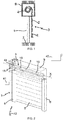
- a home automation system according to the invention and installed in a building having an opening 1, window or door, equipped with a screen 2 belonging to a concealment device 3, in particular a motorized roller shutter.
- the occulting device 3 may be a rolling shutter, as illustrated in the Figures 1 and 2 , a blind in canvas or with adjustable blades, or a rolling gate.
- the present invention applies to all types of occulting device.
- the screen 2 of the concealment device 3 is wound on a winding tube 4 driven by a motorized drive mechanism 5 and movable between a wound position, particularly high, and a unwound position, particularly low.
- the motorized drive mechanism 5 comprises an electromechanical actuator 11, in particular of the tubular type, making it possible to rotate the winding tube 4 of the concealment device 3 so as to unroll or wind up the screen 2 of the device. occultation 3.
- the electromechanical actuator 11 is inserted into the winding tube 4.
- the electromechanical actuator 11 comprises a housing 13, preferably of cylindrical shape.
- a shutter 3 comprises an apron comprising horizontal blades articulated to each other, forming the screen 2 of the shutter 3, and guided by two lateral rails 6. These blades are contiguous when the apron 2 of the shutter 3 reaches its low position unrolled.
- the wound up position corresponds to the support of a final L-shaped end plate 8 of the deck 2 of the shutter 3 against an edge of a box 9 of the shutter 3
- the lowered low position corresponds to the support of the final end blade 8 of the deck 2 of the shutter 3 against a threshold 7 of the opening 1.
- the first blade of the shutter 3, opposite to the end plate, is connected to the winding tube 4 by means of at least one hinge 10.
- the winding tube 4 is disposed inside the trunk 9 of the roller shutter 3.
- the apron 2 of the roller shutter 3 winds and unwinds around the winding tube 4 and is housed at least in part at the inside the trunk 9.
- the motorized drive mechanism 5 is controlled by a control unit.
- the control unit may be, for example, a local control unit 41, where the local control unit 41 may be wired or wirelessly connected to a central control unit 42.
- the central control unit 42 controls the control unit 41.
- local control unit 41 as well as other similar local control units distributed throughout the building.
- the central control unit 42 may be in communication with a remote weather station outside the building, including in particular one or more sensors that can be configured to determine, for example, a temperature, a brightness, or a wind speed .
- a remote control 43 which may be a type of local control unit, and provided with a control keyboard, which comprises selection and display means, also allows a user to intervene on the electromechanical actuator 11. , the local control unit 41 and / or the central control unit 42.
- the motorized drive mechanism 5 is preferably configured to execute the unwinding or winding commands of the screen 2 of the concealment device 3, which can be transmitted in particular by the remote control 43.
- Control means of the electromechanical actuator 11 according to the invention, allowing the displacement of the screen 2 of the occulting device 3, are constituted by at least one electronic control unit 44.
- This electronic control unit 44 is adapted to operate an electric motor 12 of the electromechanical actuator 11, and in particular to allow the electric power supply of the electric motor 12.
- the electronic control unit 44 controls, in particular, the electric motor 12, so as to open or close the screen 2, as described above.
- the electronic control unit 44 also comprises an order receiving module, in particular radio orders issued by a command transmitter, such as the remote control 43 intended to control the electromechanical actuator 11.
- the order receiving module can also allow the reception of orders transmitted by wire means.
- the electronic control unit 44 is disposed inside the casing 13 of the electromechanical actuator 11.
- the control means of the electromechanical actuator 11 comprise hardware and / or software means.
- the hardware means may comprise at least one microcontroller.
- the electromechanical actuator 11 is supplied with electrical energy by the power supply network of the sector, or by means of a battery, which can be recharged for example by a photovoltaic panel.
- the electromechanical actuator 11 makes it possible to move the screen 2 of the occulting device 3.
- the movable screen 2 of the concealment device 3 is a closure, concealment and / or sun protection screen, winding on the winding tube 4 whose inner diameter is substantially equivalent to the outer diameter of the electromechanical actuator 11, so that the electromechanical actuator 11 can be inserted into the winding tube 4 during assembly of the occulting device 3.
- the electromechanical actuator 11 is intended to be placed in a U-shaped rail.
- the winding tube 4 is rotated about an axis of rotation X and the casing 13 of the electromechanical actuator 11 supported by means of two pivot links.
- the first pivot connection is made at a first end of the winding tube 4 by means of a ring 18 inserted around and at one end 13a of the housing 13 of the electromechanical actuator 11.
- the ring 18 thus makes it possible to achieve a step.
- the second pivot link is performed at a second end of the winding tube 4.
- the electromechanical actuator 11 comprises a torque support 19.
- the torque support 19 protrudes at one end 13a of the housing 13 of the electromechanical actuator 11, in particular the end 13a of the housing 13 receiving the ring gear 18.
- the torque support 19 of the electromechanical actuator 11 thus makes it possible to fix the electromechanical actuator 11 on a frame 20, in particular to a cheek of the box 9.
- the torque support 19 of the electromechanical actuator 11 can make it possible to close the end 13a of the casing 13.
- the torque support 19 of the electromechanical actuator 11 can support the electronic control unit 44.
- the electronic control unit 44 can be supplied with electrical energy by means of a connected power supply cable 21 electrically to the power supply mains, or to a battery.
- the electromechanical actuator 11 comprises an electric motor 12.
- the motor 12 comprises a rotor and a stator positioned coaxially around the axis of rotation X.
- the electromechanical actuator 11 comprises a gearbox 14.
- the gearbox 14 comprises at least one reduction stage. Said at least one reduction stage may be an epicyclic gear train.
- the electromechanical actuator 11 comprises an output shaft 16. An end of the output shaft 16 protrudes with respect to the housing 13 of the electromechanical actuator 11, in particular with respect to an end 13b of the housing 13 being opposed to the end 13a of the housing 13.
- the output shaft 16 of the electromechanical actuator 11 rotates a connecting element 17 connected to the winding tube 4.
- the connecting element 17 is in the form of a wheel.
- the electromechanical actuator 11 comprises a spring brake 15.
- the electric motor 12, the gearbox 14 and the spring brake 15 are mounted inside the housing 13 of the electromechanical actuator 11.
- the spring brake 15 is arranged between the electric motor 12 and the gearbox 14, that is to say at the output of the electric motor 12.
- the spring brake 15 is arranged between two reduction stages of the gearbox 14.
- the spring brake 15 is arranged at the outlet of the gearbox 14.
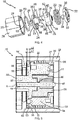
- the spring brake 15 comprises at least one helical spring 22, a drum 23, an input member 24 and an output member 25.
- the drum 23 is held in position in the housing 13 of the electromechanical actuator 11, in particular by means of ribs 28 formed on the outer periphery of the drum 23 cooperating with tongues (not shown) of a housing of the gearbox 14. And the housing of the gearbox 14 is held in position in the casing 13 of the electromechanical actuator 11.
- the drum 23 has a housing 26.
- the housing 26 of the drum 23 is cylindrical.
- the coil spring 22, the input member 24 and the output member 25 are disposed inside the housing 26 of the drum 23.
- the output member 25 is disposed opposite the body entry 24.
- the coil spring 22 has a plurality of turns.
- the turns of the coil spring 22 are centered on an axis coinciding with the axis of rotation X when the spring brake 15 is assembled and then mounted in the electromechanical actuator 11.
- the input member 24 and the body 25 are centered on an axis coincident with the axis of rotation X when the spring brake 15 is assembled and then mounted in the electromechanical actuator 11.
- An internal friction surface 27 of the housing 26 of the drum 23 cooperates with at least one coil of the coil spring 22. In this way, at least one coil of the coil spring 22 is radially constrained by the housing 26 of the drum 23.
- the coil spring 22 is mounted tightly within the housing 26 of the drum 23, so as to frictionally secure the coil spring 22 and the drum 23 when the coil spring 22 is at rest.
- Each end of the coil spring 22 forms a tab 29 extending radially or axially with respect to the axis of rotation X of the spring brake 15.
- the coil spring 22 has two lugs 29, only one of which is visible at figure 4 .
- the lugs 29 of the coil spring 22 extend radially with respect to the axis of rotation X of the spring brake 15 and towards the inside of the coil spring 22, in particular from the turns of the coil spring 22 towards the central axis of the coil spring 22.
- the input member 24 is rotated by the electric motor 12.
- the input member 24 comprises a shaft 37.
- the shaft 37 of the input member 24 can receive and transmit a torque from the electric motor 12.
- the input member 24 comprises a drive tooth 31.
- the drive tooth 31 of the input member 24 is inserted inside the coil spring, 22, when the spring brake 15 is assembled .
- the input member 24 also comprises a first plate 30.
- the first plate 30 includes the drive tooth 31.
- the drive tooth 31 of the input member 24 is disposed between the two lugs 29 of the coil spring 22 and cooperates with one or the other of the lugs 29 of the coil spring, 22, in the direction of rotation. drive generated by the electric motor 12.
- the drive tooth 31 of the input member 24 comprises two drive faces 38. Each drive face 38 of the drive tooth 31 cooperates with a tab 29 of the coil spring 22.
- the second plate 32 of the cover 33 comprises a spacer 34, arranged diametrically opposite the drive tooth 31 of the first plate 30 relative to the axis of rotation X when the spring brake 15 is assembled.
- the spacer 34 of the second plate 32 of the cover 33 thus makes it possible to maintain an axial spacing between the first and second plates 30, 32.
- the first plate 30 of the input member 24 may comprise the spacer 34.
- first and second plates 30, 32 each comprise a peripheral flange 35, 36.
- the two peripheral flanges 35, 36 are arranged facing each other along the axis of rotation X of the brake. spring 15.
- the first and second plates 30, 32 are integral in rotation around the axis of rotation X of the spring brake 15.
- first and second plates 30, 32 can be held integral in rotation around the axis of rotation X of the spring brake 15 by simple interlocking.
- first and second trays 30, 32 can be held integral in rotation around the axis of rotation X of the spring brake 15 by fixing by means of a fastening element, such as a screw of fixation.
- the output member 25 is connected to the screen 2 of the occulting device 3.
- the output member 25 comprises two lugs 39.
- the lugs 39 of the output member 25 are inserted inside the coil spring 22, when the spring brake 15 is assembled.
- the lugs 39 of the output member 25 respectively comprise a recess 40.
- the recess 40 of each of the lugs 39 of the output member 25 cooperates with one of the lugs 29 of the coil spring 22.
- the lugs 39 of the output member 25 further comprise respectively a projecting element 45.
- the projecting element 45 of each of the lugs 39 of the output member 25 extends along the axis of rotation X of the spring brake 15, and in particular towards the input member 24 when the spring brake 15 is assembled.
- the projecting element 45 of each of the lugs 39 of the output member 25 cooperates with a light 46 of the input member 24, when the spring brake 15 is assembled.
- the peripheral face of the projecting element 45 of one of the ears 39 of the output member 25 can be brought into contact with the contour of the corresponding light 46 of the input member. 24 when one of the drive faces 38 of the drive tooth 31 of the input member 24 is in contact with the face of the corresponding lug 39 of the output member 25.
- the outlet member 25 is centered with respect to the input member 24 by means of an axis 47.
- the axis 47 is inserted firstly in a bore 48 of the outlet member 25 and in a bore 49 of the input member 24.
- the input member 24, in particular the drive tooth 31, cooperates with at least one of the lugs 29 of the coil spring 22 so as to rotate the helical spring 22 around the axis of rotation X of the spring brake 15 in a first direction of rotation.
- this movement tends to reduce the diameter of the outer casing of the coil spring 22 and thus to reduce the radial stress between the coil spring 22 and the internal friction surface 27 of the housing 26 of the drum 23.
- the movement generated by the electric motor 12 can be transmitted from the input member 24 to the output member 25.
- the outer casing of the coil spring 22 is defined by the external generatrices of the turns of the coil spring 22.
- the output member 25, in particular one of the lugs 39, cooperates with at least one of the lugs 29 of the helical spring 22 so as to rotate the helical spring 22 around the axis of rotation X of the brake spring 15 in a second direction of rotation.
- Such a movement activates the spring brake 15, that is to say, tends to block or to slow the rotation of the coil spring 22 inside the housing 26 of the rotary drum 23.
- this movement tends to increase the diameter of the outer casing of the coil spring 22, in particular by bringing the tabs 29 of the coil spring 22 closer together, and thus to increase the radial stress between the coil spring 22 and the inner surface of the coil spring 22. friction 27 of the housing 26 of the drum 23.
- the spring brake 15 also comprises a ring 50 disposed between an outer surface 51 of the input member 24 and the internal friction surface 27 of the housing 26 of the drum 23.
- the ring 50 disposed between the outer surface 51 of the input member 24 and the internal friction surface 27 of the housing 26 of the drum 23 reduces the operating noise of the spring brake 15 during the drive. rotation of the input member 24 and / or the output member 25 inside the housing 26 of the drum 23.
- the ring 50 makes it possible to overcome the operating noise of the spring brake 15 linked to the friction of the outer surface 51 of the input member 24 against the internal friction surface 27 of the housing 26 of the drum 23. since the input member 24 can no longer be in direct contact with the internal friction surface 27 of the housing 26 of the drum 23, in a radial direction.
- the ring 50 disposed between the outer surface 51 of the input member 24 and the internal friction surface 27 of the housing 26 of the drum 23 allows the sliding without direct contact of the input member 24 against the housing 26 of the drum 23, during the rotational drive of the input member 24 relative to the housing 26 of the drum 23.
- the ring 50 disposed between the outer surface 51 of the input member 24 and the internal friction surface 27 of the housing 26 of the drum 23 serves as a bearing between the input member 24 and the housing 26 of the drum 23.
- the ring 50 disposed between the outer surface 51 of the input member 24 and the internal friction surface 27 of the housing 26 of the drum 23 makes it possible to make up for the misalignment of the input member 24 and or the output member 25 with respect to the axis of rotation X of the spring brake 15, so as to avoid contact between the input member 24 and the output member 25 with the internal friction surface 27 of the housing 26 of the drum 23 which can generate operating noise of the spring brake 15.
- the spring brake 15 comprises a ring 50 disposed between an outer surface 52 of the outlet member 25 and the internal friction surface 27 of the housing 26 of the drum 23 to replace the ring 50 disposed between the outer surface 51 of the input member 24 and the internal friction surface 27 of the housing 26 of the drum 23.
- the ring 50 disposed between the outer surface 52 of the outlet member 25 and the internal friction surface 27 of the housing 26 of the drum 23 makes it possible to reduce the operating noise of the spring brake 15 during the rotary drive of FIG. the input member 24 and / or the output member 25 inside the housing 26 of the drum 23.
- the ring 50 disposed between the outer surface 52 of the outlet member 25 and the internal friction surface 27 of the housing 26 of the drum 23 makes it possible to make up for the misalignment of the output member 25 and / or the input member 24 with respect to the axis of rotation X of the spring brake 15, so as to avoid contact between the input member 24 and the output member 25 with the internal friction surface 27 of the housing 26 of the drum 23 which can generate operating noise of the spring brake 15.
- the spring brake 15 comprises a first ring 50 disposed between an outer surface 51 of the input member 24 and the internal friction surface 27 of the housing 26 of the drum 23, and a second ring 50 disposed between an outer surface 52 of the outlet member 25 and the internal friction surface 27 of the housing 26 of the drum 23.
- the ring 50 is made of plastic.
- the ring 50 disposed between the outer surface 51, 52 of the input member 24 and / or the output member 25 and the internal friction surface 27 of the housing 26 of the drum 23 allows for a bearing, so as to ensure the sliding between the input member 24 and / or the output member 25 and the drum 23 without direct contact, during the rotational drive of the input member 24 and / or the outlet member 25 relative to the housing 26 of the drum 23.
- the plastic material of the ring 50 may be polyoxymethylene or "POM".
- the input member 24 and the output member 25 are made of zamac (acronym for the names of the metals that compose it: zinc, aluminum, magnesium and copper) and the drum 23 is made of steel , especially sintered steel.
- the use of the zamac to achieve the input member 24 and the output member 25 ensures a good accuracy of the dimensions of these parts during their manufacture.
- the use of sintered steel to produce the drum 23 makes it possible to reduce the resistance to friction against the internal friction surface 27 of the housing 26 of the drum 23.
- the input member 24 comprises a housing 53, where the ring 50 is disposed at the housing 53.
- the ring 50 is positioned axially with respect to the input member 24 by means of the housing 53 along the axis of rotation X of the spring brake 15.
- the output 25 comprises a housing not shown, where the ring 50 is disposed at the housing.
- the housing 53 or equivalent of the input member 24 and / or the output member 25 is a shoulder.
- the ring 50 is held in position along the axis of rotation X of the spring brake 15 between the shoulder 53 of the input member 24 and a shoulder 54 of the drum 23.
- the ring 50 is held in position along the axis of rotation X of the spring brake 15 between a first shoulder 53 of the input member 24 and a second shoulder 54 of the drum 23.
- the spring brake 15 comprises a ring 50 disposed between the outer surface 52 of the outlet member 25 and the internal friction surface 27 of the housing 26 of the drum 23, the ring 50 is maintained in position along the axis of rotation X of the spring brake 15 between the shoulder of the outlet member 25 and a shoulder of the drum 23.
- the ring 50 has a thickness L1 greater than the depth L2 of the housing 53 formed in the input member 24, along the axis of rotation X of the spring brake 15.
- one of the lateral faces of the ring 50 cooperates with the shoulder 54 of the drum 23, in particular with a lateral face of the shoulder 54 of the drum 23, the lateral face of the shoulder 54 of the drum 23 being orthogonal to the axis of rotation X of the spring brake 15.
- the ring 50 makes it possible to overcome the operating noise of the spring brake 15 linked to the friction of the outer surface of the first plate 30 of the input member 24 against the shoulder 54 of the drum 23 since input member 24 can no longer be in direct contact with the shoulder 54 of the drum 23, in an axial direction.
- the ring 50 disposed between the outer surface of the first plate 30 of the input member 24 and the shoulder 54 of the drum 23 also allows the sliding without direct contact of the input member 24 against the housing 26 of the drum 23, during the rotational drive of the input member 24 relative to the housing 26 of the drum 23.
- the spring brake 15 comprises a ring 50 disposed between the outer surface 52 of the outlet member 25 and the inner friction surface 27 of the housing 26 of the drum 23, the ring 50 presents a thickness greater than the depth of the housing formed in the outlet member 25, along the axis of rotation X of the spring brake 15.
- one of the lateral faces of the ring 50 cooperates with the shoulder of the drum 23, in particular with a lateral face of the shoulder of the drum 23, the lateral face of the shoulder of the drum 23 being orthogonal to the axis of rotation X of the spring brake 15.
- the ring 50 comprises a rotational locking element 55.
- the rotational locking element 55 of the ring 50 cooperates with an opening 56 formed in the input member 24.
- the anti-rotation device of the ring 50 relative to the input member 24 prevents premature wear of the ring 50 due to friction of the ring 50 on the outer surface 51 of the body 24, in particular when the input member 24 is made of a material such as Zamac.
- the rotational locking element 55 of the ring 50 is a tab extending from the ring constituting the ring 50 towards the center of the ring 50.
- the opening 56 formed in the input member 24, in particular in the first plate 30, cooperates with the tongue forming the rotational locking element 55 of the ring 50.
- the spring brake 15 comprises a ring 50 disposed between the outer surface 52 of the outlet member 25 and the internal friction surface 27 of the housing 26 of the drum 23, the ring 50 comprises a rotational locking element, not shown.
- the locking element in rotation of the ring 50 cooperates with an opening in the input member 25.
- the drum 23, the input member 24 and the output member 25 are parts of revolution.
- the outer diameter of the ring or rings 50 is greater than the external diameter of the inlet member 24 and the outer diameter of the outlet member 25.
- the one or more rings 50 disposed between the outer surface 51 of the input member 24 and the internal friction surface 27 of the housing 26 of the drum 23 and / or between the outer surface 52 of the outlet member 25 and the internal friction surface 27 of the housing 26 of the drum 23 make it possible to avoid direct contact between the input member 24 and the housing 26 of the drum 23 and between the output member 25 and the housing 26 of the drum 23. interposing the ring or rings 50 between them.
- the pivot connection between the input member 24 and the housing 26 of the drum 23 and between the output member 25 and the housing 26 of the drum 23 is implemented via the one or more rings 50, so as to guarantee a sliding limiting the operating noise of the spring brake 15 during the rotational drive of the input member 24 and / or the output member 25 inside the housing 26 of the drum 23.
- the inside diameter of the housing 26 of the drum 23 at the internal friction surface 27 of the housing 26 of the drum 23 is greater than the outside diameter of the ring or rings 50.
- the ring or rings 50 can be mounted with a free fit inside the housing 26 of the drum 23.
- the internal diameter of the housing 26 of the drum 23 at the internal friction surface 27 of the housing 26 of the drum 23 is smaller than the external diameter of the ring or rings 50.
- the ring or rings 50 can be mounted with a tight fit inside the housing 26 of the drum 23.
- the one or more rings 50 may be pre-mounted inside the housing 26 of the drum 23 so as to avoid the withdrawal of the ring 50 in the direction of the axis of rotation X of the spring brake 15.
- the ring or rings disposed between the outer surface of the input member and / or the output member and the internal friction surface of the drum housing can reduce the noise of operation of the brake on springs during the rotational drive of the input member and / or the output member within the drum housing.
- the ring can be attached to or be an integral part of the input member and / or the output member, in particular in the case of an electromechanical actuator having an electric motor providing a low torque.
- the ring and the input member and / or the output member form a single subassembly or a single piece, for example plastic.
Landscapes
- Engineering & Computer Science (AREA)
- Structural Engineering (AREA)
- Architecture (AREA)
- Civil Engineering (AREA)
- Power Engineering (AREA)
- Braking Arrangements (AREA)
- Operating, Guiding And Securing Of Roll- Type Closing Members (AREA)
Priority Applications (1)
| Application Number | Priority Date | Filing Date | Title |
|---|---|---|---|
| PL15172240T PL2957705T3 (pl) | 2014-06-17 | 2015-06-16 | Elektromechaniczny człon wykonawczy oraz instalacja dla budynku zawierająca taki człon wykonawczy |
Applications Claiming Priority (1)
| Application Number | Priority Date | Filing Date | Title |
|---|---|---|---|
| FR1455553A FR3022289B1 (fr) | 2014-06-17 | 2014-06-17 | Actionneur electromecanique et installation domotique comprenant un tel actionneur |
Publications (2)
| Publication Number | Publication Date |
|---|---|
| EP2957705A1 EP2957705A1 (fr) | 2015-12-23 |
| EP2957705B1 true EP2957705B1 (fr) | 2016-12-28 |
Family
ID=51726639
Family Applications (1)
| Application Number | Title | Priority Date | Filing Date |
|---|---|---|---|
| EP15172240.2A Active EP2957705B1 (fr) | 2014-06-17 | 2015-06-16 | Actionneur électromécanique et installation domotique comprenant un tel actionneur |
Country Status (5)
| Country | Link |
|---|---|
| US (1) | US20150364969A1 (pl) |
| EP (1) | EP2957705B1 (pl) |
| CN (1) | CN105178836B (pl) |
| FR (1) | FR3022289B1 (pl) |
| PL (1) | PL2957705T3 (pl) |
Families Citing this family (14)
| Publication number | Priority date | Publication date | Assignee | Title |
|---|---|---|---|---|
| CN105489123A (zh) * | 2016-01-04 | 2016-04-13 | 京东方科技集团股份有限公司 | 一种显示装置 |
| EP3443192B1 (en) * | 2016-04-14 | 2020-11-11 | Dimon Systems AB | Apparatus for vertically closing an opening and method for identifying a service need and/or a safety issue for the same |
| USD797060S1 (en) * | 2016-09-28 | 2017-09-12 | AXIS Labs, Inc. | Lift-control device for window coverings |
| TWI759419B (zh) | 2017-02-06 | 2022-04-01 | 美商漢特道格拉斯股份有限公司 | 用於減小馬達總成中之雜訊之方法及設備 |
| FR3065250B1 (fr) * | 2017-04-14 | 2019-07-05 | Somfy Sas | Procedes de fabrication d'un tambour et d'un frein a ressort d'un actionneur electromecanique, actionneur electromecanique et installation domotique associes |
| FR3072116B1 (fr) * | 2017-10-10 | 2019-11-08 | Somfy Activites Sa | Actionneur electromecanique tubulaire et installation domotique comprenant un tel actionneur |
| FR3074516B1 (fr) | 2017-12-01 | 2019-11-22 | Somfy Activites Sa | Actionneur electromecanique et installation domotique comprenant un tel actionneur |
| FR3084690B1 (fr) * | 2018-08-01 | 2020-10-23 | Somfy Activites Sa | Module mecanique de filtrage de vibrations, actionneur electromecanique comprenant un tel module mecanique de filtrage de vibrations et installation de fermeture, d'occultation ou de protection solaire comprenant un tel actionneur electromecanique |
| FR3086688B1 (fr) * | 2018-09-28 | 2020-11-06 | Somfy Activites Sa | Actionneur electromecanique comprenant un module de filtrage de vibrations et installation de fermeture, d'occultation ou de protection solaire comprenant un tel actionneur electromecanique |
| FR3087817B1 (fr) * | 2018-10-26 | 2020-11-13 | Somfy Activites Sa | Actionneur electromecanique et installation domotique comprenant un tel actionneur |
| JP7244010B2 (ja) * | 2019-05-14 | 2023-03-22 | 立川ブラインド工業株式会社 | 電動ブラインドの駆動装置、および、電動ブラインド |
| FR3111155B1 (fr) * | 2020-06-09 | 2022-10-14 | Somfy Activites Sa | Actionneur électromécanique d’un dispositif d’occultation et dispositif d’occultation comprenant un tel actionneur électromécanique |
| FR3152163B1 (fr) | 2023-08-14 | 2025-08-22 | Somfy Activites Sa | Actionneur électromécanique et dispositif d’occultation comprenant un tel actionneur électromécanique |
| FR3152164B1 (fr) * | 2023-08-14 | 2025-08-22 | Somfy Activites Sa | Actionneur électromécanique et dispositif d’occultation comprenant un tel actionneur électromécanique |
Family Cites Families (10)
| Publication number | Priority date | Publication date | Assignee | Title |
|---|---|---|---|---|
| US2673730A (en) * | 1948-10-28 | 1954-03-30 | Hupp Arleigh Glynn | Spring for spring clutches |
| US4579201A (en) * | 1983-05-16 | 1986-04-01 | Curtiss Wright Flight Systems, Inc. | Bidirectional, torque-limiting, no-back clutch mechanism |
| FR2610668B1 (fr) * | 1987-02-09 | 1990-10-26 | Feller Samuel | Reducteur-frein notamment pour la manoeuvre de volets roulants et similaires |
| CN2151241Y (zh) * | 1992-09-11 | 1993-12-29 | 黄狮 | 电动卷门制动装置 |
| FR2749361B1 (fr) * | 1996-05-28 | 1998-08-07 | Somfy | Reducteur avec accouplement de holdam |
| CN2642980Y (zh) * | 2003-08-30 | 2004-09-22 | 朱明龙 | 一种电动卷帘门传动装置 |
| US7863791B2 (en) * | 2007-10-26 | 2011-01-04 | The Bergquist Torrington Company | Device and method for assembling electric motor |
| FR2946997B1 (fr) * | 2009-06-23 | 2011-07-08 | Somfy Sas | Actionneur electrique d'entrainement d'un ecran domotique |
| CN202280414U (zh) * | 2011-10-18 | 2012-06-20 | 添成金属股份有限公司 | 电动卷门机的煞车改良装置 |
| FR2995001B1 (fr) * | 2012-09-05 | 2014-09-26 | Somfy Sas | Actionneur electromecanique d'entrainement d'un ecran domotique |
-
2014
- 2014-06-17 FR FR1455553A patent/FR3022289B1/fr active Active
-
2015
- 2015-06-15 US US14/739,001 patent/US20150364969A1/en not_active Abandoned
- 2015-06-16 EP EP15172240.2A patent/EP2957705B1/fr active Active
- 2015-06-16 CN CN201510331059.3A patent/CN105178836B/zh active Active
- 2015-06-16 PL PL15172240T patent/PL2957705T3/pl unknown
Non-Patent Citations (1)
| Title |
|---|
| None * |
Also Published As
| Publication number | Publication date |
|---|---|
| FR3022289B1 (fr) | 2016-06-03 |
| CN105178836B (zh) | 2018-07-03 |
| US20150364969A1 (en) | 2015-12-17 |
| FR3022289A1 (fr) | 2015-12-18 |
| EP2957705A1 (fr) | 2015-12-23 |
| CN105178836A (zh) | 2015-12-23 |
| PL2957705T3 (pl) | 2017-07-31 |
Similar Documents
| Publication | Publication Date | Title |
|---|---|---|
| EP2957705B1 (fr) | Actionneur électromécanique et installation domotique comprenant un tel actionneur | |
| EP3717728B1 (fr) | Actionneur électromécanique et installation domotique comprenant un tel actionneur | |
| EP3803021B1 (fr) | Dispositif d'occultation pour une installation domotique de fermeture ou de protection solaire d'un batiment et installation domotique associee | |
| EP2886785B1 (fr) | Dispositif d'entraînement motorisé d'un tube d'enroulement pour un écran appartenant à un dispositif d'occultation | |
| EP3830374B1 (fr) | Module mécanique de filtrage de vibrations, actionneur électromécanique comprenant un tel module mécanique de filtrage de vibrations et installation de fermeture, d'occultation ou de protection solaire comprenant un tel actionneur électromécanique | |
| EP3528310B1 (fr) | Dispositif de stockage d'énergie électrique, dispositif d'entraînement motorisé et installation domotique associés | |
| EP3504393B1 (fr) | Dispositif d'entraînement motorisé pour une installation domotique de fermeture ou de protection solaire et installation domotique associée | |
| EP3695087B1 (fr) | Actionneur électromécanique tubulaire, installation domotique comprenant un tel actionneur et procédé d'assemblage d'un tel actionneur | |
| WO2019072839A1 (fr) | Actionneur électromécanique tubulaire, installation domotique comprenant un tel actionneur et procédé d'assemblage d'un tel actionneur | |
| EP2922183B1 (fr) | Actionneur électromécanique, installation domotique associée et procédé de fabrication d'un tel actionneur | |
| WO2019072841A1 (fr) | Actionneur électromécanique tubulaire et installation domotique comprenant un tel actionneur | |
| EP3857014B1 (fr) | Actionneur électromécanique comprenant un module de filtrage de vibrations et installation de fermeture, d'occultation ou de protection solaire comprenant un tel actionneur électromécanique | |
| EP3610119B1 (fr) | Procédés de fabrication d'un tambour et d'un frein à ressort d'un actionneur électromécanique, actionneur électromécanique et installation domotique associés | |
| EP3870796B1 (fr) | Actionneur électromécanique et installation domotique comprenant un tel actionneur | |
| EP2937505B1 (fr) | Installation domotique comprenant un dispositif de fixation d'un mécanisme d'entraînement motorisé d'un tube d'enroulement d'un écran dans un coffre | |
| EP3020910B1 (fr) | Dispositif d'enroulement pour un écran enroulable d'une installation domotique de fermeture ou de protection solaire | |
| EP4086423B1 (fr) | Dispositif d'entrainement motorisé d'un dispositif d'occultation et dispositif d'occultation associé | |
| EP3135852B1 (fr) | Bouchon avec un système guide-câble d'un actionneur électromécanique tubulaire pour un arbre d'enroulement | |
| FR3144185A1 (fr) | Dispositif d’entraînement motorisé, son procédé d’assemblage et dispositif d’occultation comprenant un tel dispositif d’entraînement motorisé |
Legal Events
| Date | Code | Title | Description |
|---|---|---|---|
| PUAI | Public reference made under article 153(3) epc to a published international application that has entered the european phase |
Free format text: ORIGINAL CODE: 0009012 |
|
| AK | Designated contracting states |
Kind code of ref document: A1 Designated state(s): AL AT BE BG CH CY CZ DE DK EE ES FI FR GB GR HR HU IE IS IT LI LT LU LV MC MK MT NL NO PL PT RO RS SE SI SK SM TR |
|
| AX | Request for extension of the european patent |
Extension state: BA ME |
|
| 17P | Request for examination filed |
Effective date: 20160606 |
|
| RBV | Designated contracting states (corrected) |
Designated state(s): AL AT BE BG CH CY CZ DE DK EE ES FI FR GB GR HR HU IE IS IT LI LT LU LV MC MK MT NL NO PL PT RO RS SE SI SK SM TR |
|
| GRAP | Despatch of communication of intention to grant a patent |
Free format text: ORIGINAL CODE: EPIDOSNIGR1 |
|
| INTG | Intention to grant announced |
Effective date: 20160728 |
|
| GRAS | Grant fee paid |
Free format text: ORIGINAL CODE: EPIDOSNIGR3 |
|
| GRAA | (expected) grant |
Free format text: ORIGINAL CODE: 0009210 |
|
| AK | Designated contracting states |
Kind code of ref document: B1 Designated state(s): AL AT BE BG CH CY CZ DE DK EE ES FI FR GB GR HR HU IE IS IT LI LT LU LV MC MK MT NL NO PL PT RO RS SE SI SK SM TR |
|
| REG | Reference to a national code |
Ref country code: GB Ref legal event code: FG4D Free format text: NOT ENGLISH |
|
| REG | Reference to a national code |
Ref country code: CH Ref legal event code: EP |
|
| REG | Reference to a national code |
Ref country code: AT Ref legal event code: REF Ref document number: 857468 Country of ref document: AT Kind code of ref document: T Effective date: 20170115 |
|
| REG | Reference to a national code |
Ref country code: IE Ref legal event code: FG4D Free format text: LANGUAGE OF EP DOCUMENT: FRENCH |
|
| REG | Reference to a national code |
Ref country code: DE Ref legal event code: R096 Ref document number: 602015001124 Country of ref document: DE |
|
| PG25 | Lapsed in a contracting state [announced via postgrant information from national office to epo] |
Ref country code: LV Free format text: LAPSE BECAUSE OF FAILURE TO SUBMIT A TRANSLATION OF THE DESCRIPTION OR TO PAY THE FEE WITHIN THE PRESCRIBED TIME-LIMIT Effective date: 20161228 |
|
| REG | Reference to a national code |
Ref country code: LT Ref legal event code: MG4D |
|
| PG25 | Lapsed in a contracting state [announced via postgrant information from national office to epo] |
Ref country code: NO Free format text: LAPSE BECAUSE OF FAILURE TO SUBMIT A TRANSLATION OF THE DESCRIPTION OR TO PAY THE FEE WITHIN THE PRESCRIBED TIME-LIMIT Effective date: 20170328 Ref country code: GR Free format text: LAPSE BECAUSE OF FAILURE TO SUBMIT A TRANSLATION OF THE DESCRIPTION OR TO PAY THE FEE WITHIN THE PRESCRIBED TIME-LIMIT Effective date: 20170329 Ref country code: LT Free format text: LAPSE BECAUSE OF FAILURE TO SUBMIT A TRANSLATION OF THE DESCRIPTION OR TO PAY THE FEE WITHIN THE PRESCRIBED TIME-LIMIT Effective date: 20161228 Ref country code: SE Free format text: LAPSE BECAUSE OF FAILURE TO SUBMIT A TRANSLATION OF THE DESCRIPTION OR TO PAY THE FEE WITHIN THE PRESCRIBED TIME-LIMIT Effective date: 20161228 |
|
| REG | Reference to a national code |
Ref country code: NL Ref legal event code: MP Effective date: 20161228 |
|
| REG | Reference to a national code |
Ref country code: AT Ref legal event code: MK05 Ref document number: 857468 Country of ref document: AT Kind code of ref document: T Effective date: 20161228 |
|
| REG | Reference to a national code |
Ref country code: FR Ref legal event code: PLFP Year of fee payment: 3 |
|
| PG25 | Lapsed in a contracting state [announced via postgrant information from national office to epo] |
Ref country code: HR Free format text: LAPSE BECAUSE OF FAILURE TO SUBMIT A TRANSLATION OF THE DESCRIPTION OR TO PAY THE FEE WITHIN THE PRESCRIBED TIME-LIMIT Effective date: 20161228 Ref country code: FI Free format text: LAPSE BECAUSE OF FAILURE TO SUBMIT A TRANSLATION OF THE DESCRIPTION OR TO PAY THE FEE WITHIN THE PRESCRIBED TIME-LIMIT Effective date: 20161228 Ref country code: RS Free format text: LAPSE BECAUSE OF FAILURE TO SUBMIT A TRANSLATION OF THE DESCRIPTION OR TO PAY THE FEE WITHIN THE PRESCRIBED TIME-LIMIT Effective date: 20161228 |
|
| PG25 | Lapsed in a contracting state [announced via postgrant information from national office to epo] |
Ref country code: NL Free format text: LAPSE BECAUSE OF FAILURE TO SUBMIT A TRANSLATION OF THE DESCRIPTION OR TO PAY THE FEE WITHIN THE PRESCRIBED TIME-LIMIT Effective date: 20161228 |
|
| PG25 | Lapsed in a contracting state [announced via postgrant information from national office to epo] |
Ref country code: IS Free format text: LAPSE BECAUSE OF FAILURE TO SUBMIT A TRANSLATION OF THE DESCRIPTION OR TO PAY THE FEE WITHIN THE PRESCRIBED TIME-LIMIT Effective date: 20170428 Ref country code: SK Free format text: LAPSE BECAUSE OF FAILURE TO SUBMIT A TRANSLATION OF THE DESCRIPTION OR TO PAY THE FEE WITHIN THE PRESCRIBED TIME-LIMIT Effective date: 20161228 Ref country code: RO Free format text: LAPSE BECAUSE OF FAILURE TO SUBMIT A TRANSLATION OF THE DESCRIPTION OR TO PAY THE FEE WITHIN THE PRESCRIBED TIME-LIMIT Effective date: 20161228 Ref country code: EE Free format text: LAPSE BECAUSE OF FAILURE TO SUBMIT A TRANSLATION OF THE DESCRIPTION OR TO PAY THE FEE WITHIN THE PRESCRIBED TIME-LIMIT Effective date: 20161228 Ref country code: CZ Free format text: LAPSE BECAUSE OF FAILURE TO SUBMIT A TRANSLATION OF THE DESCRIPTION OR TO PAY THE FEE WITHIN THE PRESCRIBED TIME-LIMIT Effective date: 20161228 |
|
| PG25 | Lapsed in a contracting state [announced via postgrant information from national office to epo] |
Ref country code: SM Free format text: LAPSE BECAUSE OF FAILURE TO SUBMIT A TRANSLATION OF THE DESCRIPTION OR TO PAY THE FEE WITHIN THE PRESCRIBED TIME-LIMIT Effective date: 20161228 Ref country code: ES Free format text: LAPSE BECAUSE OF FAILURE TO SUBMIT A TRANSLATION OF THE DESCRIPTION OR TO PAY THE FEE WITHIN THE PRESCRIBED TIME-LIMIT Effective date: 20161228 Ref country code: BG Free format text: LAPSE BECAUSE OF FAILURE TO SUBMIT A TRANSLATION OF THE DESCRIPTION OR TO PAY THE FEE WITHIN THE PRESCRIBED TIME-LIMIT Effective date: 20170328 Ref country code: PT Free format text: LAPSE BECAUSE OF FAILURE TO SUBMIT A TRANSLATION OF THE DESCRIPTION OR TO PAY THE FEE WITHIN THE PRESCRIBED TIME-LIMIT Effective date: 20170428 Ref country code: AT Free format text: LAPSE BECAUSE OF FAILURE TO SUBMIT A TRANSLATION OF THE DESCRIPTION OR TO PAY THE FEE WITHIN THE PRESCRIBED TIME-LIMIT Effective date: 20161228 |
|
| REG | Reference to a national code |
Ref country code: DE Ref legal event code: R097 Ref document number: 602015001124 Country of ref document: DE |
|
| PLBE | No opposition filed within time limit |
Free format text: ORIGINAL CODE: 0009261 |
|
| STAA | Information on the status of an ep patent application or granted ep patent |
Free format text: STATUS: NO OPPOSITION FILED WITHIN TIME LIMIT |
|
| PG25 | Lapsed in a contracting state [announced via postgrant information from national office to epo] |
Ref country code: DK Free format text: LAPSE BECAUSE OF FAILURE TO SUBMIT A TRANSLATION OF THE DESCRIPTION OR TO PAY THE FEE WITHIN THE PRESCRIBED TIME-LIMIT Effective date: 20161228 |
|
| 26N | No opposition filed |
Effective date: 20170929 |
|
| PG25 | Lapsed in a contracting state [announced via postgrant information from national office to epo] |
Ref country code: MC Free format text: LAPSE BECAUSE OF FAILURE TO SUBMIT A TRANSLATION OF THE DESCRIPTION OR TO PAY THE FEE WITHIN THE PRESCRIBED TIME-LIMIT Effective date: 20161228 |
|
| PG25 | Lapsed in a contracting state [announced via postgrant information from national office to epo] |
Ref country code: SI Free format text: LAPSE BECAUSE OF FAILURE TO SUBMIT A TRANSLATION OF THE DESCRIPTION OR TO PAY THE FEE WITHIN THE PRESCRIBED TIME-LIMIT Effective date: 20161228 |
|
| REG | Reference to a national code |
Ref country code: IE Ref legal event code: MM4A |
|
| PG25 | Lapsed in a contracting state [announced via postgrant information from national office to epo] |
Ref country code: IE Free format text: LAPSE BECAUSE OF NON-PAYMENT OF DUE FEES Effective date: 20170616 Ref country code: LU Free format text: LAPSE BECAUSE OF NON-PAYMENT OF DUE FEES Effective date: 20170616 |
|
| REG | Reference to a national code |
Ref country code: BE Ref legal event code: MM Effective date: 20170630 |
|
| REG | Reference to a national code |
Ref country code: FR Ref legal event code: PLFP Year of fee payment: 4 |
|
| PG25 | Lapsed in a contracting state [announced via postgrant information from national office to epo] |
Ref country code: BE Free format text: LAPSE BECAUSE OF NON-PAYMENT OF DUE FEES Effective date: 20170630 |
|
| PG25 | Lapsed in a contracting state [announced via postgrant information from national office to epo] |
Ref country code: MT Free format text: LAPSE BECAUSE OF FAILURE TO SUBMIT A TRANSLATION OF THE DESCRIPTION OR TO PAY THE FEE WITHIN THE PRESCRIBED TIME-LIMIT Effective date: 20161228 |
|
| REG | Reference to a national code |
Ref country code: CH Ref legal event code: PL |
|
| PG25 | Lapsed in a contracting state [announced via postgrant information from national office to epo] |
Ref country code: LI Free format text: LAPSE BECAUSE OF NON-PAYMENT OF DUE FEES Effective date: 20180630 Ref country code: CH Free format text: LAPSE BECAUSE OF NON-PAYMENT OF DUE FEES Effective date: 20180630 |
|
| PG25 | Lapsed in a contracting state [announced via postgrant information from national office to epo] |
Ref country code: HU Free format text: LAPSE BECAUSE OF FAILURE TO SUBMIT A TRANSLATION OF THE DESCRIPTION OR TO PAY THE FEE WITHIN THE PRESCRIBED TIME-LIMIT; INVALID AB INITIO Effective date: 20150616 |
|
| PG25 | Lapsed in a contracting state [announced via postgrant information from national office to epo] |
Ref country code: CY Free format text: LAPSE BECAUSE OF FAILURE TO SUBMIT A TRANSLATION OF THE DESCRIPTION OR TO PAY THE FEE WITHIN THE PRESCRIBED TIME-LIMIT Effective date: 20161228 |
|
| PG25 | Lapsed in a contracting state [announced via postgrant information from national office to epo] |
Ref country code: MK Free format text: LAPSE BECAUSE OF FAILURE TO SUBMIT A TRANSLATION OF THE DESCRIPTION OR TO PAY THE FEE WITHIN THE PRESCRIBED TIME-LIMIT Effective date: 20161228 |
|
| GBPC | Gb: european patent ceased through non-payment of renewal fee |
Effective date: 20190616 |
|
| PG25 | Lapsed in a contracting state [announced via postgrant information from national office to epo] |
Ref country code: TR Free format text: LAPSE BECAUSE OF FAILURE TO SUBMIT A TRANSLATION OF THE DESCRIPTION OR TO PAY THE FEE WITHIN THE PRESCRIBED TIME-LIMIT Effective date: 20161228 |
|
| PG25 | Lapsed in a contracting state [announced via postgrant information from national office to epo] |
Ref country code: GB Free format text: LAPSE BECAUSE OF NON-PAYMENT OF DUE FEES Effective date: 20190616 |
|
| PG25 | Lapsed in a contracting state [announced via postgrant information from national office to epo] |
Ref country code: AL Free format text: LAPSE BECAUSE OF FAILURE TO SUBMIT A TRANSLATION OF THE DESCRIPTION OR TO PAY THE FEE WITHIN THE PRESCRIBED TIME-LIMIT Effective date: 20161228 |
|
| REG | Reference to a national code |
Ref country code: DE Ref legal event code: R082 Ref document number: 602015001124 Country of ref document: DE Representative=s name: LAVOIX MUNICH, DE Ref country code: DE Ref legal event code: R081 Ref document number: 602015001124 Country of ref document: DE Owner name: SOMFY ACTIVITIES SA, FR Free format text: FORMER OWNER: SOMFY SAS, CLUSES, FR Ref country code: DE Ref legal event code: R081 Ref document number: 602015001124 Country of ref document: DE Owner name: SOMFY ACTIVITES SA, FR Free format text: FORMER OWNER: SOMFY SAS, CLUSES, FR |
|
| REG | Reference to a national code |
Ref country code: DE Ref legal event code: R082 Ref document number: 602015001124 Country of ref document: DE Representative=s name: LAVOIX MUNICH, DE Ref country code: DE Ref legal event code: R081 Ref document number: 602015001124 Country of ref document: DE Owner name: SOMFY ACTIVITES SA, FR Free format text: FORMER OWNER: SOMFY ACTIVITIES SA, CLUSES, FR |
|
| PGFP | Annual fee paid to national office [announced via postgrant information from national office to epo] |
Ref country code: PL Payment date: 20250526 Year of fee payment: 11 Ref country code: DE Payment date: 20250617 Year of fee payment: 11 |
|
| PGFP | Annual fee paid to national office [announced via postgrant information from national office to epo] |
Ref country code: FR Payment date: 20250425 Year of fee payment: 11 |
|
| PGFP | Annual fee paid to national office [announced via postgrant information from national office to epo] |
Ref country code: IT Payment date: 20250606 Year of fee payment: 11 |