EP2957484A2 - Kotflügel für ein fahrzeug, vorzugsweise nutzfahrzeug - Google Patents
Kotflügel für ein fahrzeug, vorzugsweise nutzfahrzeug Download PDFInfo
- Publication number
- EP2957484A2 EP2957484A2 EP15001572.5A EP15001572A EP2957484A2 EP 2957484 A2 EP2957484 A2 EP 2957484A2 EP 15001572 A EP15001572 A EP 15001572A EP 2957484 A2 EP2957484 A2 EP 2957484A2
- Authority
- EP
- European Patent Office
- Prior art keywords
- fender
- mudguard
- recess
- vehicle
- wheel
- Prior art date
- Legal status (The legal status is an assumption and is not a legal conclusion. Google has not performed a legal analysis and makes no representation as to the accuracy of the status listed.)
- Granted
Links
Images



Classifications
-
- B—PERFORMING OPERATIONS; TRANSPORTING
- B62—LAND VEHICLES FOR TRAVELLING OTHERWISE THAN ON RAILS
- B62D—MOTOR VEHICLES; TRAILERS
- B62D25/00—Superstructure or monocoque structure sub-units; Parts or details thereof not otherwise provided for
- B62D25/08—Front or rear portions
- B62D25/16—Mud-guards or wings; Wheel cover panels
- B62D25/168—Mud guards for utility vehicles
Definitions
- the invention relates to a mudguard for a commercial vehicle, which ends with a curvature adapted to the tire shape, in downwardly directed to the roadway legs, as well as a commercial vehicle, for.
- a bus or a truck which is equipped with at least one fender invention.
- the object of the invention is in particular to create a mounting location on the vehicle on which a chock can be arranged by default regardless of the size and features while taking up as little space as possible.
- wheel arch is used in the context of the present invention instead of the term “mudguard”. Both terms are to be regarded as synonymous in the context of the present invention.
- a fender for a vehicle preferably a commercial vehicle, which ends with a shape adapted to the curvature in downwardly directed to the road legs, the curvature having a recess, hereinafter referred to as a recess in which the Radunterlegkeil is detachably halterbar and / or is held.
- the wheel chock is thus integrated in the fender or the wheel arch of the vehicle.
- the integration can take place via a component integration, such that the wheel chock in the salient state forms a functional part of the mudguard, z. B. by the chock forms a part of the tire facing wall of the fender.
- the wheel chock is integrated into a part of the fender itself and z. B. rests on a part of the tire facing wall of the fender.
- a particular advantage of the invention is therefore that the chocks always have a firmly defined mounting space on the vehicle and also take no additional space elsewhere on the vehicle.
- the integration in the fender also has the advantage that a chock is mounted directly in the vicinity of the tire, which facilitates handling for the driver.
- Another advantage is that such supported chocks can fit nicely and unobtrusively into the design and overall appearance of the vehicle.
- a holding device for supporting the fender may be provided, which extends in the horizontal direction in the recess, and the Radunterlegkeil may have a through hole, which is executed, the holding device at least partially take.
- the recess is provided in the region of a fender carrier or a fender support, wherein the fender support also serves as the holding device.
- the fender carrier may be designed as a cylindrical retaining bolt which is fixed to a vehicle frame side member of a commercial vehicle and extending in the horizontal direction.
- the wheel chock is integrated in the fender or the wheel arch of the vehicle and in this case can form a functional part of the fender.
- the wheel chock may, in the exception held state form a part of the inner and / or outer surface of the fender and / or be formed as an integral functional component portion of the fender.
- the chock together with a tire facing inner surface of the fender form a tire cover.
- a wheel chock in use with the mudguard according to the invention can thus fulfill a dual function:
- the wheel chock can be arranged on the wheel to serve as a conventional wheel rolling protection and take over a mudguard protection function in the retained state. This reduces the cost of materials for the fender and the required space on the vehicle.
- a particularly compact arrangement can be realized when the Radunterlegkeil formed in the exception held state a portion of one of the downwardly directed to the road leg, wherein a tire facing inner surface of the fender is partially formed of a wheel support surface of Radunterlegkeils.
- the inner surface of the mudguard or of the wheel well is thus composed of the inner surface of the curvature and the wheel support surface of the wheel chock in the retained state of the wheel chock, wherein the wheel support surface of the wheel chock closes the recess in the inner surface in a puzzle-like manner.
- the wheel chock can be integrated in the installation space of the fender or wheel arch of the vehicle.
- a tire facing the Be formed inside surface of the fender in the region of the recess as a support surface for a wheel support surface of Radunterlegkeils.
- This variant offers the advantage that the inner surface of the curvature is designed without gaps and at the same time serves as a support for the retained wheel chock.
- a width of the recess of the curvature substantially corresponds to a width of Radunterlegkeils and / or that a first part of a back of the Radunterlegkeils is pushed in the salaried state under the curvature and a second part, comprising a handle , exposed.
- the chock can be arranged so that his back is facing up.
- the lock is formed as a retaining lug or latching lug, which is designed to be able to engage around a handle of the wheel chock in the retained state of the Radunterlegkeils.
- the invention is not limited to a particular axis with respect to the vehicle axle.
- the fender according to the invention can be provided on any axis (front axle, rear axle, leading and trailing axle).
- the number of provided chocks is variable.
- One or more fenders according to the invention may be provided with one wheel chock per vehicle.
- the right side or the left side of the vehicle can be selected as the installation side, with the driver side being preferred for quick access.
- the invention also relates to a motor vehicle, preferably a utility vehicle, in particular a bus or a truck, with a fender or wheel arch as disclosed herein.
- a motor vehicle preferably a utility vehicle, in particular a bus or a truck, with a fender or wheel arch as disclosed herein.
- FIG. 1 shows a schematic view of a mudguard 10 with retained chock 1 according to an embodiment of the invention.
- the fender 10 can be arranged on a vehicle axle (not shown) which is designed as a front, rear, forward or trailing axle.
- the mudguard 10, which ends with a curvature adapted to the tire shape 14 in downwardly directed to the roadway legs 11 a, 11 b, is fixed to the frame on a vehicle frame side member 7 of the vehicle body via cylindrical fender supports 13 (see also FIG. 2 ) attached.
- the legs For attachment to the fender props, the legs have horizontally extending slots 18, which are adapted to the diameter of the fender props 13.
- the Radunterlegkeil 1 is substantially triangular in shape, with a straight bottom surface 2, a back 4 and a curved wheel support surface 3, the curvature of which is adapted to the curvature of the inner surface 17 of the bulge 14 in the region of the front leg 11a.
- the curvature 14 has a recess 15 in which the Radunterlegkeil 1 is detachably supported.
- the recess 15 is in the illustration of FIG. 2 better to see.
- the chock 1 is removed from the fender 10 and arranged in a wheel-roll-protection position on the wheel 8.
- the front leg 11a is compared to the rear leg 11 b with a smaller width (extension in the horizontal direction) executed.
- the contour of the chock 1 is in through the recess 15 predetermined space fitted.
- the width of the recess 15 of the curvature 14 corresponds for example substantially to the width of Radunterlegkeils first
- a through hole 6 is introduced in the form of a slot in its central region, which extends transversely to the direction of travel F.
- a through hole 6 is introduced in the form of a slot in its central region, which extends transversely to the direction of travel F.
- the wheel support surface 3 of the wheel chock 1 together with a tire 8 facing inner surface 17 of the fender 10 forms a tire overlap.
- the Radunterlegkeil 1 formed in the state held in the exception 15 with its bottom surface 2 forms a portion of the front leg portion of the curvature 14 from.
- the wheel chock 1 has with its bottom surface 2 in the direction of travel F forward.
- the back 4 points upward.
- the wheel chock 1 thus forms a part of the inner and / or outer surface 16, 17 of the fender 10 in the retained state in the exception 15 and is designed as an integral functional component portion of the fender 10 in terms of component integration.
- the wheel chock 1 also assumes the wheel protection functions of a fender when driving, for example, the wheel support surface 3 serves as a splash guard surface.
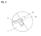
- a retaining lug 12 which is designed to be able to embrace the handle 5 of the Radunterlegkeils in the retained state of the Radunterlegkeils 1 and secure in a form-fitting manner. This is in FIG. 3 shown in a detailed view.
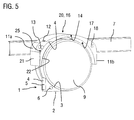
- FIGS. 4 and 5 illustrate another embodiment of the invention.
- components with the same reference numerals correspond to the components of FIGS. 1 and 2 and will not be described separately.
- the peculiarity of this embodiment lies in the fact that the wheel chock is integrated in a part of the fender 20 itself in the sense of a space integration.
- the curvature 14 in turn in the region of the front leg 11a has a recess 25 which is adapted to the contour of the wheel chock 1 and in the Radunterlegkeil 1 according to FIG. 4 is detachably held.
- the convex-curved inner surface 17 has no recess, but extends substantially semicircularly from the rear leg 11 b to the front leg 11a. In the region of the recess 25, this serves as a support surface for a wheel support surface 3 of Radunterlegkeils 1. Further, a holding plate 21 is attached to the front leg 11a, which serves as a support and support plate for the bottom surface 2 of the content hindered wheel chock 1. The width of the plate 21 corresponds to the width of the rear leg 11 b and thus covers the front of the front leg 11 a and the bottom surface 2 of the wheel chock the first
Landscapes
- Engineering & Computer Science (AREA)
- Chemical & Material Sciences (AREA)
- Combustion & Propulsion (AREA)
- Transportation (AREA)
- Mechanical Engineering (AREA)
- Body Structure For Vehicles (AREA)
- Arrangement Or Mounting Of Propulsion Units For Vehicles (AREA)
Abstract
Description
- Die Erfindung betrifft einen Kotflügel für ein Nutzfahrzeug, der mit einer der Reifenform angepassten Wölbung, in nach unten zur Fahrbahn gerichteten Schenkeln endet, sowie ein Nutzfahrzeug, z. B. einen Omnibus oder einen Lastkraftwagen, das mit wenigstens einem erfindungsgemäßen Kotflügel ausgerüstet ist.
- Üblicherweise werden Radunterlegkeile, nachfolgend auch als Unterlegkeile bezeichnet, als lose Einzelteile in einer Halterung am Rahmen von Nutzfahrzeugen mitgeführt. Der Halter befindet sich für unterschiedliche Nutzfahrzeuge jedoch immer wieder an unterschiedlichen Einbauorten am Rahmen, abhängig von Größe und Ausstattung der Fahrzeuge und je nachdem, wo jeweils Fahrzeugtyp-spezifisch ausreichend Platz zur Anbringung des Radunterlegkeils ist. In der
DE 102 09 162 A1 wird beispielsweise vorgeschlagen, eine Außenflanke eines Längsträgers von Sattelanhänger-Fahrgestellrahmen, insbesondere deren Kröpfungsbereich, als Anbringungsort für einen Radunterlegkeil zu verwenden. Nachteilig ist daher, dass Fahrer von Nutzfahrzeugen in Gefahrensituationen den Anbringungsort des Unterlegkeils erst ausfindig machen müssen, um durch Unterlegen des Unterlegkeils ein mögliches Wegrollen des Nutzfahrzeugs zu verhindern. - Ferner ist aus der
DE 10 2010 024 409 A1 ein gattungsgemäßer Kotflügel für ein Nutzfahrzeug bekannt, an dessen Außenseite der Kotflügelwölbung ein zur Aufnahme eines Unterlegkeils bestimmter Stauraum mit einer Öffnung angeordnet ist. Die Anbringung des Unterlegkeils in direkter Nähe des Reifens erleichtert die Handhabung für den Fahrer. Nachteilig hierbei ist jedoch, dass an der Außenseite des Kotflügels zusätzlicher Bauraum beansprucht wird. - Es ist somit eine Aufgabe der Erfindung, eine verbesserte Anbringmöglichkeit an Fahrzeugen für einen Unterlegkeil bereitzustellen, mit dem Nachteile herkömmlicher Anbringungstechniken vermieden werden können. Die Aufgabe der Erfindung ist es insbesondere, einen Anbringungsort am Fahrzeug schaffen, an dem ein Unterlegkeil unabhängig von der Größe und Ausstattung standardmäßig angeordnet werden kann und dabei möglichst wenig Bauraum beansprucht.
- Diese Aufgaben werden durch einen Kotflügel bzw. einem Radkasten eines Fahrzeugs mit den Merkmalen des Hauptanspruchs gelöst. Vorteilhafte Ausführungsformen und Anwendungen der Erfindung sind Gegenstand der abhängigen Ansprüche und werden in der folgenden Beschreibung unter teilweiser Bezugnahme auf die Figuren näher erläutert.
- Gegebenenfalls wird im Rahmen der vorliegenden Erfindung statt des Begriffs "Kotflügel" auch der Begriff "Radkasten" verwendet. Beide Begriffe sind im Rahmen der vorliegenden Erfindung als gleichbedeutend anzusehen.
- Erfindungsgemäß wird ein Kotflügel für ein Fahrzeug, vorzugsweise Nutzfahrzeug, vorgeschlagen, der mit einer der Reifenform angepassten Wölbung in nach unten zur Fahrbahn gerichteten Schenkeln endet, wobei die Wölbung eine Ausnehmung aufweist, nachfolgend auch als Aussparung bezeichnet, in der der Radunterlegkeil abnehmbar halterbar ist und/oder gehaltert ist.
- Gemäß allgemeinen Gesichtspunkten der Erfindung ist der Unterlegkeil somit in den Kotflügel bzw. den Radkasten des Fahrzeugs integriert. Hierbei kann die Integration über eine Bauteilintegration erfolgen, derart, dass der Unterlegkeil im gehalterten Zustand einen funktionalen Teil des Kotflügels ausbildet, z. B., indem der Unterlegkeil einen Teil der dem Reifen zugewandten Wandung des Kotflügels ausbildet. Alternativ besteht auch die Möglichkeit einer Bauraumintegration, wobei der Unterlegkeil in einen Teil des Kotflügels selbst integriert ist und z. B. auf einem Teil der dem Reifen zugewandten Wandung des Kotflügels aufliegt.
- Ein besonderer Vorzug der Erfindung liegt somit darin, dass die Unterlegkeile immer einen fest definierten Anbringungsplatz am Fahrzeug haben und ferner keinen zusätzlichen Bauraum anderweitig am Fahrzeug in Anspruch nehmen. Die Integration in den Kotflügel bietet ferner den Vorteil, dass ein Unterlegkeil direkt in Nähe des Reifens angebracht ist, was die Handhabung für den Fahrer erleichtert. Ein weiterer Vorteil ist, dass sich derart gehalterte Unterlegkeile ansprechend und unauffällig in das Design und die Gesamterscheinung des Fahrzeugs einfügen können.
- Besonders vorteilhaft ist, wenn die Kontur des Unterlegkeils in den durch die Ausnehmung vorgegebenen Bauraum eingepasst ist, was eine besonders kompakte Ausführung ermöglicht.
- Ferner kann eine Halteeinrichtung zur Halterung des Kotflügels vorgesehen sein, die sich in Horizontalrichtung in die Ausnehmung erstreckt, und der Radunterlegkeil kann eine Durchgangsöffnung aufweisen, die ausgeführt ist, die Halteeinrichtung zumindest bereichsweise aufzunehmen. Dadurch kann ein einfach zu handhabender und platzsparender Halterungsmechanismus bereitgestellt werden.
- Bei einer vorteilhaften Variante dieser Ausgestaltungsform ist die Ausnehmung im Bereich eines Kotflügelträgers bzw. einer Kotflügelstütze vorgesehen, wobei die Kotflügelstütze gleichzeitig als die Halteeinrichtung dient. Dies bieten den Vorteil, dass keine separate Halteeinrichtung vorgesehen werden muss, sondern der bestehende am Fahrzeugrahmen befestigte Kotflügelträger zusätzlich zur Halterung des Unterlegkeils genutzt werden kann.
- Der Kotflügelträger kann als zylinderförmiger Haltebolzen ausgeführt sein, der an einem Fahrzeugrahmenlängsträger eines Nutzfahrzeugs befestigt ist und sich in Horizontalrichtung erstreckt.
- Es wurde vorstehend bereits erwähnt, dass der Unterlegkeil in den Kotflügel bzw. den Radkasten des Fahrzeugs integriert ist und hierbei einen funktionalen Teil des Kotflügels ausbilden kann. Gemäß dieser Variante kann der Radunterlegkeil im in der Ausnahme gehalterten Zustand einen Teil der Innen- und/oder Außenfläche des Kotflügels ausbilden und/oder als integraler funktionaler Bauteilbereich des Kotflügels ausgebildet sein. Beispielsweise kann der Unterlegkeil zusammen mit einer dem Reifen zugewandten Innenfläche des Kotflügels eine Reifenüberdeckung ausbilden. Ein Unterlegkeil in Verwendung mit dem erfindungsgemäßen Kotflügel kann somit eine Doppelfunktion ausfüllen: Der Unterlegkeil kann am Rad angeordnet als herkömmlicher Rad-Wegrollschutz dienen und im gehalterten Zustand eine Kotflügelschutzfunktion übernehmen. Dies reduziert den Materialaufwand für den Kotflügel und den benötigten Bauraum am Fahrzeug.
- Eine besonders kompakte Anordnung ist realisierbar, wenn der Radunterlegkeil im in der Ausnahme gehalterten Zustand einen Teilabschnitt einer der nach unten zur Fahrbahn gerichteten Schenkel ausbildet, wobei eine dem Reifen zugewandte Innenfläche des Kotflügels teilweise aus einer Rad-Stützfläche des Radunterlegkeils gebildet wird. Die Innenfläche des Kotflügels bzw. des Radkastens setzt sich im gehalterten Zustand des Unterlegkeils somit aus der Innenfläche der Wölbung und der Rad-Stützfläche des Unterlegkeils zusammen, wobei die Rad-Stützfläche des Unterlegkeils die durch die Ausnehmung entstehende Aussparung in der Innenfläche puzzleartig schließt.
- Es wurde vorstehend bereits erwähnt, dass der Unterlegkeil in den Bauraum des Kotflügels bzw. des Radkastens des Fahrzeugs integriert sein kann. Hierbei kann eine dem Reifen zugewandte Innenfläche des Kotflügels im Bereich der Ausnehmung als Auflagefläche für eine Rad-Stützfläche des Radunterlegkeils ausgebildet sein. Diese Variante bietet den Vorteil, dass die Innenfläche der Wölbung spaltfrei ausgeführt ist und gleichzeitig als Abstützung für den gehalterten Unterlegkeil dient.
- Für eine optimale Bauraumausnutzung ist es ferner möglich, dass eine Breite der Ausnehmung der Wölbung im Wesentlichen einer Breite des Radunterlegkeils entspricht und/oder dass ein erster Teil eines Rückens des Radunterlegkeils im gehalterten Zustand unter die Wölbung geschoben ist und ein zweiter Teil, aufweisend einen Handgriff, freiliegt. Der Unterlegkeil kann dabei so angeordnet sein, dass sein Rücken nach oben weist.
- Eine Möglichkeit der erfindungsgemäßen Realisierung sieht ferner vor, dass an einem Rand der Ausnehmung eine Arretierung für den gehalterten Radunterlegkeil vorgesehen ist. Damit kann der gehalterte Unterlegkeil für den Fahrbetrieb sicher fixiert werden. Bei einer vorteilhaften Variante dieser Ausgestaltungsform ist die Arretierung als Haltenase bzw. Rastnase ausgebildet ist, die ausgeführt ist, im gehalterten Zustand des Radunterlegkeils einen Handgriff des Radunterlegkeils einrastbar umgreifen zu können.
- Die Erfindung ist hinsichtlich der Fahrzeugachse nicht auf eine bestimmte Achse beschränkt. Der erfindungsgemäße Kotflügel kann an einer beliebigen Achse (Vorderachse, Hinterachse, Vor- und Nachlaufachse) vorgesehen sein. Ferner ist die Anzahl der vorgesehenen Unterlegkeile variabel. Es können ein oder mehrere erfindungsgemäße Kotflügel mit einem Unterlegkeil pro Fahrzeug vorgesehen sein. Ferner kann als Einbauseite die rechte oder die linke Fahrzeugseite gewählt werden, wobei für den schnellen Zugriff die Fahrerseite bevorzugt ist.
- Die Erfindung betrifft ebenso ein Kraftfahrzeug, vorzugsweise ein Nutzfahrzeug, insbesondere einen Omnibus oder einen Lastkraftwagen, mit einem Kotflügel bzw. Radkasten wie hierin offenbart.
- Die zuvor beschriebenen bevorzugten Ausführungsformen und Merkmale der Erfindung sind beliebig miteinander kombinierbar. Weitere Einzelheiten und Vorteile der Erfindung werden im Folgenden unter Bezug auf die beigefügten Zeichnungen beschrieben. Es zeigen:
- Figur 1
- eine schematische Ansicht eines Kotflügels mit einem gehalterten Unterlegkeil gemäß einer Ausführungsform der Erfindung;
- Figur 2
- eine schematische Ansicht des Kotflügels aus
Figur 1 mit dem Unterlegkeil in einer Rad-Wegroll-Schutz-Stellung; - Figur 3
- eine Detailansicht der Haltenase;
- Figur 4
- eine schematische Ansicht eines Kotflügels mit einem gehalterten Unterlegkeil gemäß einer weiteren Ausführungsform der Erfindung; und
- Figur 5
- eine schematische Ansicht des Kotflügels aus
Figur 4 mit dem Unterlegkeil in einer Rad-Wegroll-Schutz-Stellung. - Gleiche oder funktional äquivalente Elemente sind in allen Figuren mit denselben Bezugszeichen bezeichnet.
-
Figur 1 zeigt eine schematische Ansicht eines Kotflügels 10 mit gehaltertem Unterlegkeil 1 gemäß einer Ausführungsform der Erfindung. Der Kotflügel 10 kann an einer als Vorder-, Hinter, Vorlauf- oder Nachlaufachse ausgebildeten Fahrzeugachse (nicht gezeigt) angeordnet sein. Der Kotflügel 10, der mit einer der Reifenform angepassten Wölbung 14 in nach unten zur Fahrbahn gerichteten Schenkeln 11 a, 11 b endet, ist rahmenfest an einem Fahrzeugrahmenlängsträger 7 des Fahrzeugaufbaus über zylinderförmige Kotflügelstützen 13 (siehe auchFigur 2 ) befestigt. Zur Befestigung an den Kotflügelstützen weisen die Schenkel sich horizontal erstreckende Langlöcher 18 auf, die an den Durchmesser der Kotflügelstützen 13 angepasst sind. - Der Radunterlegkeil 1 ist im Wesentlichen dreiecksförmig ausgebildet, mit einer gerade Bodenfläche 2, einem Rücken 4 und einer gekrümmten Rad-Stützfläche 3, deren Krümmung an die Krümmung der Innenfläche 17 der Wölbung 14 im Bereich des vorderen Schenkels 11a angepasst ist.
- Die Wölbung 14 weist eine Ausnehmung 15 auf, in der der Radunterlegkeil 1 abnehmbar gehaltert ist. Die Ausnehmung 15 ist in der Darstellung der
Figur 2 besser zu sehen. In dieser Darstellung ist der Unterlegkeil 1 vom Kotflügel 10 abgenommen und in einer Rad-Wegroll-Schutz-Stellung am Rad 8 angeordnet. Durch die Ausnehmung "fehlt" somit ein Teil des Kotflügels 10 bzw. der Wölbung 14 an vorderen Endbereich. Hierbei ist der vordere Schenkel 11a im Vergleich zum hinteren Schenkel 11 b mit geringerer Breite (Erstreckung in Horizontalrichtung) ausgeführt. Die Kontur des Unterlegkeils 1 ist in den durch die Ausnehmung 15 vorgegebenen Bauraum eingepasst. Die Breite der Ausnehmung 15 der Wölbung 14 entspricht beispielsweise im Wesentlichen der Breite des Radunterlegkeils 1. - In den Unterlegkeil 1 ist in seinem Mittenbereich eine Durchgangsöffnung 6 im Form eines Langlochs eingebracht, die quer zur Fahrtrichtung F verläuft. Zur Anbringung des Unterlegkeils 1 an dem Kotflügel 10 wird der Unterlegkeil mittels der Durchgangsöffnung 6 auf den Endbereich der Kotflügelstütze 13 aufgesteckt. In dem gehalterten Zustand ist ein erster Teil des Rückens 4 des Radunterlegkeils 1 unter die Wölbung 14 geschoben, die mit einem die Ausnehmung 15 begrenzenden Randbereich flächig auf diesem ersten Teil des Rückens 4 aufliegt. Ein zweiter Teil des Rücken liegt frei. An diesem Teil ist ein Handgriff 5 befestigt.
- Im gehalterten Zustand bildet die Rad-Stützfläche 3 des Unterlegkeils 1 zusammen mit einer dem Reifen 8 zugewandte Innenfläche 17 des Kotflügels 10 eine Reifenüberdeckung aus. Ferner bildet der Radunterlegkeil 1 im in der Ausnahme 15 gehalterten Zustand mit seiner Bodenfläche 2 einen Teilabschnitt des vorderen Schenkelbereichs der Wölbung 14 aus. Der Unterlegkeil 1 weist dabei mit seiner Bodenfläche 2 in Fahrtrichtung F nach vorne. Der Rücken 4 weist nach oben.
- Der Radunterlegkeil 1 bildet somit in dem in der Ausnahme 15 gehalterten Zustand einen Teil der Innen- und/oder Außenfläche 16, 17 des Kotflügels 10 aus und ist im Sinne einer Bauteilintegration als integraler funktionaler Bauteilbereich des Kotflügels 10 ausgeführt. Somit übernimmt der Unterlegkeil 1 im Fahrbetrieb ebenfalls die Radschutzfunktionen eines Kotflügels, beispielsweise dient die Rad-Stützfläche 3 als Spritzschutzfläche.
- Zur verliersicheren Befestigung ist der Unterlegkeil 11 zusätzlich über eine Haltenase 12 gesichert, die ausgeführt ist, im gehalterten Zustand des Radunterlegkeils 1 den Handgriff 5 des Radunterlegkeils umgreifen zu können und formschlüssig zu sichern. Dies ist in
Figur 3 in einer Detailansicht dargestellt. - Die
Figuren 4 und5 illustrieren eine weitere Ausführungsform der Erfindung. Hierbei entsprechen Komponenten mit gleichen Bezugszeichen den Komponenten derFiguren 1 und2 und werden nicht gesondert beschrieben. Die Besonderheit dieser Ausführungsform liegt darin, dass der Unterlegkeil im Sinne einer Bauraumintegration in einen Teil des Kotflügels 20 selbst integriert ist. - Hierzu weist die Wölbung 14 wiederum im Bereich des vorderen Schenkels 11a eine Aussparung 25 auf, die an die Kontur des Unterlegkeils 1 angepasst ist und in der der Radunterlegkeil 1 gemäß
Figur 4 abnehmbar gehaltert ist. - Im Unterschied zum Kotflügel 10 der
Figuren 1 und2 weist die konvex-gewölbte Innenfläche 17 keine Aussparung auf, sondern verläuft im Wesentlichen halbkreisförmig durchgehend vom hinteren Schenkel 11 b zum vorderen Schenkel 11a. In dem Bereich der Ausnehmung 25 dient diese als Auflagefläche für eine Rad-Stützfläche 3 des Radunterlegkeils 1. Ferner ist am vorderen Schenkel 11a eine Halteplatte 21 befestigt, die als Halte- und Stützplatte für die Bodenfläche 2 des gehalterten Unterlegkeils 1 dient. Die Breite der Platte 21 entspricht der Breite des hinteren Schenkels 11 b und überdeckt somit die Vorderseite des vorderen Schenkels 11a sowie die Bodenfläche 2 des Unterlegkeils 1. - Die Erfindung ist nicht auf die oben beschriebenen bevorzugten Ausführungsformen beschränkt. Vielmehr ist eine Vielzahl von Varianten und Abwandlungen möglich, die ebenfalls von dem Erfindungsgedanken Gebrauch machen und deshalb in den Schutzbereich fallen. Darüber hinaus beansprucht die Erfindung auch Schutz für den Gegenstand und die Merkmale der Unteransprüche unabhängig von den in Bezug genommenen Merkmalen und Ansprüchen.
-
- 1
- Radunterlegkeil
- 2
- Bodenfläche
- 3
- Rad-Stützfläche
- 4
- Rücken
- 5
- Handgriff
- 6
- Durchgangsöffnung
- 7
- Rahmenlängsträger
- 8
- Reifen
- 10
- Kotflügel
- 11 a
- Vorderer Schenkel
- 11 b
- Hinterer Schenkel
- 12
- Haltenase
- 13
- Kotflügelstütze
- 14
- Wölbung
- 15
- Ausnehmung
- 16
- Außenseite
- 17
- Innenseite
- 18
- Durchgangsöffnung
- 20
- Kotflügel
- 21
- Halteplatte
- 22
- Auflagefläche
- 25
- Ausnehmung
- F
- Fahrtrichtung
Claims (10)
- Kotflügel (10; 20) für ein Fahrzeug, vorzugsweise Nutzfahrzeug, der mit einer der Reifenform angepassten Wölbung (14) in nach unten zur Fahrbahn gerichteten Schenkeln (11a, 11b) endet, wobei die Wölbung (14) eine Ausnehmung (15; 25) aufweist, in der der Radunterlegkeil (1) abnehmbar halterbar ist und/oder gehaltert ist.
- Kotflügel (10; 20) nach Anspruch 1, dadurch gekennzeichnet, dass sich eine Halteeinrichtung zur Halterung des Kotflügels in Horizontalrichtung in die Ausnehmung erstreckt und der Radunterlegkeil (1) eine Durchgangsöffnung (6) aufweist, die ausgeführt ist, die Halteeinrichtung zumindest bereichsweise aufzunehmen.
- Kotflügel (10; 20) nach Anspruch 2, dadurch gekennzeichnet, dass die Ausnehmung (15; 25) im Bereich einer Kotflügelstütze (13) vorgesehen ist, die gleichzeitig als die Halteeinrichtung dient.
- Kotflügel (10) nach einem der vorhergehenden Ansprüche, dadurch gekennzeichnet, dass der Radunterlegkeil (1) im in der Ausnahme (15) gehalterten Zustand(a) einen Teil der Innen- und/oder Außenfläche (16, 17) des Kotflügels (10) ausbildet; und/oder(b) als integraler funktionaler Bauteilbereich des Kotflügels (10) ausgebildet ist; und/oder(c) zusammen mit einer dem Reifen (8) zugewandte Innenfläche (17) des Kotflügels (10) eine Reifenüberdeckung ausbildet
- Kotflügel (10) nach einem der vorhergehenden Ansprüche, dadurch gekennzeichnet, dass der Radunterlegkeil (1) im in der Ausnahme (15) gehalterten Zustand einen Teilabschnitt (2) einer der nach unten zur Fahrbahn gerichteten Schenkel (11a) ausbildet, wobei eine dem Reifen (8) zugewandte Innenfläche (17) des Kotflügels (10) teilweise aus einer Rad-Stützfläche (3) des Radunterlegkeils (1) gebildet wird.
- Kotflügel (20) nach einem der Ansprüche 1 bis 3, dadurch gekennzeichnet, dass eine dem Reifen (8) zugewandte Innenfläche (17) des Kotflügels (20) im Bereich der Ausnehmung (25) als Auflagefläche (22) für eine Rad-Stützfläche (3) des Radunterlegkeils (1) ausgebildet ist.
- Kotflügel (10; 20) nach einem der vorhergehenden Ansprüche, dadurch gekennzeichnet,(a) dass eine Breite der Ausnehmung (15; 25) der Wölbung (14) im Wesentlichen einer Breite des Radunterlegkeils entspricht; und/oder(b) dass ein erster Teil eines Rückens (4) des Radunterlegkeils im gehalterten Zustand unter die Wölbung (14) geschoben ist und ein zweiter Teil, aufweisend einen Handgriff (5), freiliegt.
- Kotflügel (10; 20) nach einem der vorhergehenden Ansprüche, dadurch gekennzeichnet, dass an einem Rand der Ausnehmung (15; 25) eine Arretierung für den gehalterten Radunterlegkeil (1) vorgesehen ist.
- Kotflügel (10; 20) nach Anspruch 8, dadurch gekennzeichnet, dass die Arretierung als Haltenase (12) ausgebildet ist, die ausgeführt ist, im gehalterten Zustand des Radunterlegkeils (1) einen Handgriff (5) des Radunterlegkeils umgreifen zu können.
- Kraftfahrzeug, vorzugsweise Nutzfahrzeug, mit einem Kotflügel nach einem der Ansprüche 1 bis 9.
Applications Claiming Priority (1)
| Application Number | Priority Date | Filing Date | Title |
|---|---|---|---|
| DE102014009055.8A DE102014009055A1 (de) | 2014-06-18 | 2014-06-18 | Kotflügel für ein Fahrzeug, vorzugsweise Nutzfahrzeug |
Publications (3)
| Publication Number | Publication Date |
|---|---|
| EP2957484A2 true EP2957484A2 (de) | 2015-12-23 |
| EP2957484A3 EP2957484A3 (de) | 2016-01-13 |
| EP2957484B1 EP2957484B1 (de) | 2017-03-15 |
Family
ID=53365697
Family Applications (1)
| Application Number | Title | Priority Date | Filing Date |
|---|---|---|---|
| EP15001572.5A Active EP2957484B1 (de) | 2014-06-18 | 2015-05-23 | Kotflügel für ein fahrzeug, vorzugsweise nutzfahrzeug |
Country Status (5)
| Country | Link |
|---|---|
| EP (1) | EP2957484B1 (de) |
| CN (1) | CN105313987B (de) |
| BR (1) | BR102015013302B1 (de) |
| DE (1) | DE102014009055A1 (de) |
| RU (1) | RU2675731C2 (de) |
Cited By (1)
| Publication number | Priority date | Publication date | Assignee | Title |
|---|---|---|---|---|
| EP3272594A1 (de) * | 2016-07-23 | 2018-01-24 | MAN Truck & Bus AG | Kraftfahrzeug mit einem radunterlegkeil und einer halterung für den radunterlegkeil |
Families Citing this family (1)
| Publication number | Priority date | Publication date | Assignee | Title |
|---|---|---|---|---|
| AU2021204152B2 (en) | 2021-06-21 | 2023-04-06 | Caterpillar Inc. | Wheel chock mounting assembly |
Citations (2)
| Publication number | Priority date | Publication date | Assignee | Title |
|---|---|---|---|---|
| DE10209162A1 (de) | 2002-03-01 | 2003-09-18 | Schmitz Cargobull Ag | Längsträger mit Befestigungsvorrichtung |
| DE102010024409A1 (de) | 2010-06-19 | 2011-12-22 | Man Truck & Bus Ag | Kotflügel für ein Nutzfahrzeug |
Family Cites Families (6)
| Publication number | Priority date | Publication date | Assignee | Title |
|---|---|---|---|---|
| JPS59153663A (ja) * | 1983-02-21 | 1984-09-01 | Mazda Motor Corp | 自動車のタイヤカバ−装置 |
| SU1158417A1 (ru) * | 1983-12-30 | 1985-05-30 | Lavrentyuk Vladimir V | Противооткатное устройство транспортного средства |
| DE3939937A1 (de) * | 1989-12-02 | 1991-02-28 | Daimler Benz Ag | Vorrichtung zum fangen und ableiten des von einem fahrzeugrad hochgeschleuderten spritzwassers |
| DE4118385A1 (de) * | 1991-06-05 | 1992-12-10 | Aerodynamische Autoteile Aav | Kraftfahrzeugkotfluegel mit spritzwasserablenkeinrichtungen |
| DE29713006U1 (de) * | 1997-07-22 | 1997-09-25 | Sauermann, Franz, 86558 Hohenwart | Kotflügel zur Abdeckung eines Fahrzeugrads |
| DE10133425A1 (de) * | 2001-07-10 | 2003-01-30 | Hp Chem Pelzer Res & Dev Ltd | Fahrzeug-Radhausauskleidung |
-
2014
- 2014-06-18 DE DE102014009055.8A patent/DE102014009055A1/de not_active Withdrawn
-
2015
- 2015-05-23 EP EP15001572.5A patent/EP2957484B1/de active Active
- 2015-06-08 BR BR102015013302-2A patent/BR102015013302B1/pt active IP Right Grant
- 2015-06-17 RU RU2015123472A patent/RU2675731C2/ru active
- 2015-06-18 CN CN201510339586.9A patent/CN105313987B/zh active Active
Patent Citations (2)
| Publication number | Priority date | Publication date | Assignee | Title |
|---|---|---|---|---|
| DE10209162A1 (de) | 2002-03-01 | 2003-09-18 | Schmitz Cargobull Ag | Längsträger mit Befestigungsvorrichtung |
| DE102010024409A1 (de) | 2010-06-19 | 2011-12-22 | Man Truck & Bus Ag | Kotflügel für ein Nutzfahrzeug |
Cited By (1)
| Publication number | Priority date | Publication date | Assignee | Title |
|---|---|---|---|---|
| EP3272594A1 (de) * | 2016-07-23 | 2018-01-24 | MAN Truck & Bus AG | Kraftfahrzeug mit einem radunterlegkeil und einer halterung für den radunterlegkeil |
Also Published As
| Publication number | Publication date |
|---|---|
| EP2957484A3 (de) | 2016-01-13 |
| EP2957484B1 (de) | 2017-03-15 |
| RU2675731C2 (ru) | 2018-12-24 |
| RU2015123472A3 (de) | 2018-11-22 |
| BR102015013302A2 (pt) | 2016-06-21 |
| RU2015123472A (ru) | 2017-01-10 |
| CN105313987B (zh) | 2019-09-20 |
| CN105313987A (zh) | 2016-02-10 |
| BR102015013302A8 (pt) | 2021-09-08 |
| DE102014009055A1 (de) | 2015-12-24 |
| BR102015013302B1 (pt) | 2022-07-12 |
Similar Documents
| Publication | Publication Date | Title |
|---|---|---|
| DE102013107366B4 (de) | Heckspoiler-Anordnung für Fahrzeuge, insbesondere Kraftfahrzeuge | |
| DE102016212297A1 (de) | Kraftfahrzeug | |
| DE102009050495A1 (de) | Hilfsrahmen | |
| DE102015112509A1 (de) | Abstützeinrichtung für ein Fahrzeugrad eines Kraftfahrzeugs | |
| DE102011050707A1 (de) | Lagerung eines elektrischen oder elektronischen Bauteils in einem Motorraum eines Kraftfahrzeugs | |
| DE102016115667A1 (de) | Vorrichtung zur Befestigung eines Fangnetzes in einem Fahrzeug | |
| EP2397392B1 (de) | Kotflügel für ein Nutzfahrzeug | |
| EP2957484B1 (de) | Kotflügel für ein fahrzeug, vorzugsweise nutzfahrzeug | |
| DE202013011014U1 (de) | Kraftfahrzeug mit Fixierungseinrichtung für ein Fahrrad | |
| DE102010025260A1 (de) | Traggestell zur seitlichen Befestigung von Anbauteilen an einem Längsträger einer Nutzfahrzeug-Tragstruktur | |
| EP2404814B1 (de) | Kotflügel für ein Nutzfahrzeug | |
| DE10336491B4 (de) | Halterungsanordnung zum Festlegen eines kompakten Reserverads und eines Rads mit Normalgrösse | |
| DE102016115691A1 (de) | Hintere Fahrzeugbodenstruktur | |
| EP1566309B1 (de) | Transportbehälter für Fahrzeuge für den sitzlehnen- oder kofferraumwandseitigen Einbau in Personenkraftwagen | |
| DE102020124599A1 (de) | Karosserie eines elektrisch oder teilelektrisch antreibbaren Kraftfahrzeugs | |
| EP3398810A1 (de) | Kompaktheck an nutzfahrzeugen mit ausfahrbarem heck | |
| DE19731372C2 (de) | Kraftfahrzeug | |
| DE102004014668B4 (de) | Verstrebung für einen Laderaumboden | |
| EP3130528B1 (de) | Seitenverkleidungseinrichtung für ein nutzfahrzeug | |
| DE102012020864A1 (de) | Einsteighilfe für Tiere in ein Kraftfahrzeug | |
| DE102014006718A1 (de) | Bodenstruktur für eine Personenkraftwagenkarosserie | |
| EP2368766B1 (de) | Transportbox | |
| DE202019101978U1 (de) | Trageinrichtung | |
| DE102011109462A1 (de) | Halterung für einen radkeil | |
| DE102009012237A1 (de) | Karosserie für ein Kraftfahrzeug |
Legal Events
| Date | Code | Title | Description |
|---|---|---|---|
| PUAL | Search report despatched |
Free format text: ORIGINAL CODE: 0009013 |
|
| PUAI | Public reference made under article 153(3) epc to a published international application that has entered the european phase |
Free format text: ORIGINAL CODE: 0009012 |
|
| AK | Designated contracting states |
Kind code of ref document: A2 Designated state(s): AL AT BE BG CH CY CZ DE DK EE ES FI FR GB GR HR HU IE IS IT LI LT LU LV MC MK MT NL NO PL PT RO RS SE SI SK SM TR |
|
| AX | Request for extension of the european patent |
Extension state: BA ME |
|
| AK | Designated contracting states |
Kind code of ref document: A3 Designated state(s): AL AT BE BG CH CY CZ DE DK EE ES FI FR GB GR HR HU IE IS IT LI LT LU LV MC MK MT NL NO PL PT RO RS SE SI SK SM TR |
|
| AX | Request for extension of the european patent |
Extension state: BA ME |
|
| RIC1 | Information provided on ipc code assigned before grant |
Ipc: B62D 25/16 20060101AFI20151204BHEP Ipc: B60P 3/077 20060101ALI20151204BHEP |
|
| 17P | Request for examination filed |
Effective date: 20160608 |
|
| GRAP | Despatch of communication of intention to grant a patent |
Free format text: ORIGINAL CODE: EPIDOSNIGR1 |
|
| STAA | Information on the status of an ep patent application or granted ep patent |
Free format text: STATUS: GRANT OF PATENT IS INTENDED |
|
| GRAJ | Information related to disapproval of communication of intention to grant by the applicant or resumption of examination proceedings by the epo deleted |
Free format text: ORIGINAL CODE: EPIDOSDIGR1 |
|
| GRAP | Despatch of communication of intention to grant a patent |
Free format text: ORIGINAL CODE: EPIDOSNIGR1 |
|
| INTG | Intention to grant announced |
Effective date: 20161108 |
|
| INTG | Intention to grant announced |
Effective date: 20161129 |
|
| GRAS | Grant fee paid |
Free format text: ORIGINAL CODE: EPIDOSNIGR3 |
|
| GRAA | (expected) grant |
Free format text: ORIGINAL CODE: 0009210 |
|
| STAA | Information on the status of an ep patent application or granted ep patent |
Free format text: STATUS: THE PATENT HAS BEEN GRANTED |
|
| AK | Designated contracting states |
Kind code of ref document: B1 Designated state(s): AL AT BE BG CH CY CZ DE DK EE ES FI FR GB GR HR HU IE IS IT LI LT LU LV MC MK MT NL NO PL PT RO RS SE SI SK SM TR |
|
| REG | Reference to a national code |
Ref country code: CH Ref legal event code: EP Ref country code: GB Ref legal event code: FG4D Free format text: NOT ENGLISH |
|
| REG | Reference to a national code |
Ref country code: IE Ref legal event code: FG4D Free format text: LANGUAGE OF EP DOCUMENT: GERMAN |
|
| REG | Reference to a national code |
Ref country code: AT Ref legal event code: REF Ref document number: 875219 Country of ref document: AT Kind code of ref document: T Effective date: 20170415 |
|
| REG | Reference to a national code |
Ref country code: NL Ref legal event code: FP |
|
| REG | Reference to a national code |
Ref country code: DE Ref legal event code: R096 Ref document number: 502015000693 Country of ref document: DE |
|
| REG | Reference to a national code |
Ref country code: FR Ref legal event code: PLFP Year of fee payment: 3 |
|
| REG | Reference to a national code |
Ref country code: SE Ref legal event code: TRGR |
|
| REG | Reference to a national code |
Ref country code: LT Ref legal event code: MG4D |
|
| PG25 | Lapsed in a contracting state [announced via postgrant information from national office to epo] |
Ref country code: FI Free format text: LAPSE BECAUSE OF FAILURE TO SUBMIT A TRANSLATION OF THE DESCRIPTION OR TO PAY THE FEE WITHIN THE PRESCRIBED TIME-LIMIT Effective date: 20170315 Ref country code: HR Free format text: LAPSE BECAUSE OF FAILURE TO SUBMIT A TRANSLATION OF THE DESCRIPTION OR TO PAY THE FEE WITHIN THE PRESCRIBED TIME-LIMIT Effective date: 20170315 Ref country code: GR Free format text: LAPSE BECAUSE OF FAILURE TO SUBMIT A TRANSLATION OF THE DESCRIPTION OR TO PAY THE FEE WITHIN THE PRESCRIBED TIME-LIMIT Effective date: 20170616 Ref country code: NO Free format text: LAPSE BECAUSE OF FAILURE TO SUBMIT A TRANSLATION OF THE DESCRIPTION OR TO PAY THE FEE WITHIN THE PRESCRIBED TIME-LIMIT Effective date: 20170615 Ref country code: LT Free format text: LAPSE BECAUSE OF FAILURE TO SUBMIT A TRANSLATION OF THE DESCRIPTION OR TO PAY THE FEE WITHIN THE PRESCRIBED TIME-LIMIT Effective date: 20170315 |
|
| PG25 | Lapsed in a contracting state [announced via postgrant information from national office to epo] |
Ref country code: LV Free format text: LAPSE BECAUSE OF FAILURE TO SUBMIT A TRANSLATION OF THE DESCRIPTION OR TO PAY THE FEE WITHIN THE PRESCRIBED TIME-LIMIT Effective date: 20170315 Ref country code: LU Free format text: LAPSE BECAUSE OF NON-PAYMENT OF DUE FEES Effective date: 20170531 Ref country code: BG Free format text: LAPSE BECAUSE OF FAILURE TO SUBMIT A TRANSLATION OF THE DESCRIPTION OR TO PAY THE FEE WITHIN THE PRESCRIBED TIME-LIMIT Effective date: 20170615 Ref country code: RS Free format text: LAPSE BECAUSE OF FAILURE TO SUBMIT A TRANSLATION OF THE DESCRIPTION OR TO PAY THE FEE WITHIN THE PRESCRIBED TIME-LIMIT Effective date: 20170315 |
|
| PG25 | Lapsed in a contracting state [announced via postgrant information from national office to epo] |
Ref country code: EE Free format text: LAPSE BECAUSE OF FAILURE TO SUBMIT A TRANSLATION OF THE DESCRIPTION OR TO PAY THE FEE WITHIN THE PRESCRIBED TIME-LIMIT Effective date: 20170315 Ref country code: SK Free format text: LAPSE BECAUSE OF FAILURE TO SUBMIT A TRANSLATION OF THE DESCRIPTION OR TO PAY THE FEE WITHIN THE PRESCRIBED TIME-LIMIT Effective date: 20170315 Ref country code: RO Free format text: LAPSE BECAUSE OF FAILURE TO SUBMIT A TRANSLATION OF THE DESCRIPTION OR TO PAY THE FEE WITHIN THE PRESCRIBED TIME-LIMIT Effective date: 20170315 Ref country code: ES Free format text: LAPSE BECAUSE OF FAILURE TO SUBMIT A TRANSLATION OF THE DESCRIPTION OR TO PAY THE FEE WITHIN THE PRESCRIBED TIME-LIMIT Effective date: 20170315 Ref country code: CZ Free format text: LAPSE BECAUSE OF FAILURE TO SUBMIT A TRANSLATION OF THE DESCRIPTION OR TO PAY THE FEE WITHIN THE PRESCRIBED TIME-LIMIT Effective date: 20170315 |
|
| PG25 | Lapsed in a contracting state [announced via postgrant information from national office to epo] |
Ref country code: SM Free format text: LAPSE BECAUSE OF FAILURE TO SUBMIT A TRANSLATION OF THE DESCRIPTION OR TO PAY THE FEE WITHIN THE PRESCRIBED TIME-LIMIT Effective date: 20170315 Ref country code: IS Free format text: LAPSE BECAUSE OF FAILURE TO SUBMIT A TRANSLATION OF THE DESCRIPTION OR TO PAY THE FEE WITHIN THE PRESCRIBED TIME-LIMIT Effective date: 20170715 Ref country code: PT Free format text: LAPSE BECAUSE OF FAILURE TO SUBMIT A TRANSLATION OF THE DESCRIPTION OR TO PAY THE FEE WITHIN THE PRESCRIBED TIME-LIMIT Effective date: 20170717 Ref country code: PL Free format text: LAPSE BECAUSE OF FAILURE TO SUBMIT A TRANSLATION OF THE DESCRIPTION OR TO PAY THE FEE WITHIN THE PRESCRIBED TIME-LIMIT Effective date: 20170315 |
|
| REG | Reference to a national code |
Ref country code: DE Ref legal event code: R097 Ref document number: 502015000693 Country of ref document: DE |
|
| PLBE | No opposition filed within time limit |
Free format text: ORIGINAL CODE: 0009261 |
|
| STAA | Information on the status of an ep patent application or granted ep patent |
Free format text: STATUS: NO OPPOSITION FILED WITHIN TIME LIMIT |
|
| PG25 | Lapsed in a contracting state [announced via postgrant information from national office to epo] |
Ref country code: DK Free format text: LAPSE BECAUSE OF FAILURE TO SUBMIT A TRANSLATION OF THE DESCRIPTION OR TO PAY THE FEE WITHIN THE PRESCRIBED TIME-LIMIT Effective date: 20170315 Ref country code: MC Free format text: LAPSE BECAUSE OF FAILURE TO SUBMIT A TRANSLATION OF THE DESCRIPTION OR TO PAY THE FEE WITHIN THE PRESCRIBED TIME-LIMIT Effective date: 20170315 |
|
| 26N | No opposition filed |
Effective date: 20171218 |
|
| REG | Reference to a national code |
Ref country code: IE Ref legal event code: MM4A |
|
| PG25 | Lapsed in a contracting state [announced via postgrant information from national office to epo] |
Ref country code: SI Free format text: LAPSE BECAUSE OF FAILURE TO SUBMIT A TRANSLATION OF THE DESCRIPTION OR TO PAY THE FEE WITHIN THE PRESCRIBED TIME-LIMIT Effective date: 20170315 |
|
| PG25 | Lapsed in a contracting state [announced via postgrant information from national office to epo] |
Ref country code: LU Free format text: LAPSE BECAUSE OF NON-PAYMENT OF DUE FEES Effective date: 20170523 |
|
| REG | Reference to a national code |
Ref country code: BE Ref legal event code: MM Effective date: 20170531 |
|
| PG25 | Lapsed in a contracting state [announced via postgrant information from national office to epo] |
Ref country code: IE Free format text: LAPSE BECAUSE OF NON-PAYMENT OF DUE FEES Effective date: 20170523 |
|
| REG | Reference to a national code |
Ref country code: FR Ref legal event code: PLFP Year of fee payment: 4 |
|
| PG25 | Lapsed in a contracting state [announced via postgrant information from national office to epo] |
Ref country code: BE Free format text: LAPSE BECAUSE OF NON-PAYMENT OF DUE FEES Effective date: 20170531 |
|
| PG25 | Lapsed in a contracting state [announced via postgrant information from national office to epo] |
Ref country code: MT Free format text: LAPSE BECAUSE OF FAILURE TO SUBMIT A TRANSLATION OF THE DESCRIPTION OR TO PAY THE FEE WITHIN THE PRESCRIBED TIME-LIMIT Effective date: 20170315 |
|
| REG | Reference to a national code |
Ref country code: CH Ref legal event code: PL |
|
| PG25 | Lapsed in a contracting state [announced via postgrant information from national office to epo] |
Ref country code: CH Free format text: LAPSE BECAUSE OF NON-PAYMENT OF DUE FEES Effective date: 20180531 Ref country code: LI Free format text: LAPSE BECAUSE OF NON-PAYMENT OF DUE FEES Effective date: 20180531 |
|
| PG25 | Lapsed in a contracting state [announced via postgrant information from national office to epo] |
Ref country code: HU Free format text: LAPSE BECAUSE OF FAILURE TO SUBMIT A TRANSLATION OF THE DESCRIPTION OR TO PAY THE FEE WITHIN THE PRESCRIBED TIME-LIMIT; INVALID AB INITIO Effective date: 20150523 |
|
| REG | Reference to a national code |
Ref country code: DE Ref legal event code: R081 Ref document number: 502015000693 Country of ref document: DE Owner name: MAN TRUCK & BUS SE, DE Free format text: FORMER OWNER: MAN TRUCK & BUS AG, 80995 MUENCHEN, DE |
|
| PG25 | Lapsed in a contracting state [announced via postgrant information from national office to epo] |
Ref country code: CY Free format text: LAPSE BECAUSE OF FAILURE TO SUBMIT A TRANSLATION OF THE DESCRIPTION OR TO PAY THE FEE WITHIN THE PRESCRIBED TIME-LIMIT Effective date: 20170315 |
|
| PG25 | Lapsed in a contracting state [announced via postgrant information from national office to epo] |
Ref country code: MK Free format text: LAPSE BECAUSE OF FAILURE TO SUBMIT A TRANSLATION OF THE DESCRIPTION OR TO PAY THE FEE WITHIN THE PRESCRIBED TIME-LIMIT Effective date: 20170315 |
|
| GBPC | Gb: european patent ceased through non-payment of renewal fee |
Effective date: 20190523 |
|
| PG25 | Lapsed in a contracting state [announced via postgrant information from national office to epo] |
Ref country code: TR Free format text: LAPSE BECAUSE OF FAILURE TO SUBMIT A TRANSLATION OF THE DESCRIPTION OR TO PAY THE FEE WITHIN THE PRESCRIBED TIME-LIMIT Effective date: 20170315 |
|
| PG25 | Lapsed in a contracting state [announced via postgrant information from national office to epo] |
Ref country code: GB Free format text: LAPSE BECAUSE OF NON-PAYMENT OF DUE FEES Effective date: 20190523 |
|
| PG25 | Lapsed in a contracting state [announced via postgrant information from national office to epo] |
Ref country code: AL Free format text: LAPSE BECAUSE OF FAILURE TO SUBMIT A TRANSLATION OF THE DESCRIPTION OR TO PAY THE FEE WITHIN THE PRESCRIBED TIME-LIMIT Effective date: 20170315 |
|
| REG | Reference to a national code |
Ref country code: AT Ref legal event code: MM01 Ref document number: 875219 Country of ref document: AT Kind code of ref document: T Effective date: 20200523 |
|
| PG25 | Lapsed in a contracting state [announced via postgrant information from national office to epo] |
Ref country code: AT Free format text: LAPSE BECAUSE OF NON-PAYMENT OF DUE FEES Effective date: 20200523 |
|
| PGFP | Annual fee paid to national office [announced via postgrant information from national office to epo] |
Ref country code: NL Payment date: 20250526 Year of fee payment: 11 |
|
| PGFP | Annual fee paid to national office [announced via postgrant information from national office to epo] |
Ref country code: DE Payment date: 20250528 Year of fee payment: 11 |
|
| PGFP | Annual fee paid to national office [announced via postgrant information from national office to epo] |
Ref country code: IT Payment date: 20250522 Year of fee payment: 11 |
|
| PGFP | Annual fee paid to national office [announced via postgrant information from national office to epo] |
Ref country code: FR Payment date: 20250526 Year of fee payment: 11 |
|
| PGFP | Annual fee paid to national office [announced via postgrant information from national office to epo] |
Ref country code: SE Payment date: 20250526 Year of fee payment: 11 |