EP2956993B1 - Federklemmkontakt und verbindungsklemme für elektrische leiter - Google Patents
Federklemmkontakt und verbindungsklemme für elektrische leiter Download PDFInfo
- Publication number
- EP2956993B1 EP2956993B1 EP14704143.8A EP14704143A EP2956993B1 EP 2956993 B1 EP2956993 B1 EP 2956993B1 EP 14704143 A EP14704143 A EP 14704143A EP 2956993 B1 EP2956993 B1 EP 2956993B1
- Authority
- EP
- European Patent Office
- Prior art keywords
- clamping
- section
- resilient
- contact
- spring
- Prior art date
- Legal status (The legal status is an assumption and is not a legal conclusion. Google has not performed a legal analysis and makes no representation as to the accuracy of the status listed.)
- Active
Links
- 239000004020 conductor Substances 0.000 title claims description 59
- 239000011810 insulating material Substances 0.000 claims description 12
- 238000003780 insertion Methods 0.000 description 7
- 230000037431 insertion Effects 0.000 description 7
- 230000001154 acute effect Effects 0.000 description 3
- 229910000639 Spring steel Inorganic materials 0.000 description 2
- 230000007704 transition Effects 0.000 description 2
- RYGMFSIKBFXOCR-UHFFFAOYSA-N Copper Chemical compound [Cu] RYGMFSIKBFXOCR-UHFFFAOYSA-N 0.000 description 1
- 229910052802 copper Inorganic materials 0.000 description 1
- 239000010949 copper Substances 0.000 description 1
- 239000000463 material Substances 0.000 description 1
- 239000002184 metal Substances 0.000 description 1
- 229910052751 metal Inorganic materials 0.000 description 1
- 239000007769 metal material Substances 0.000 description 1
- 238000004080 punching Methods 0.000 description 1
- 210000002105 tongue Anatomy 0.000 description 1
Images


Classifications
-
- H—ELECTRICITY
- H01—ELECTRIC ELEMENTS
- H01R—ELECTRICALLY-CONDUCTIVE CONNECTIONS; STRUCTURAL ASSOCIATIONS OF A PLURALITY OF MUTUALLY-INSULATED ELECTRICAL CONNECTING ELEMENTS; COUPLING DEVICES; CURRENT COLLECTORS
- H01R4/00—Electrically-conductive connections between two or more conductive members in direct contact, i.e. touching one another; Means for effecting or maintaining such contact; Electrically-conductive connections having two or more spaced connecting locations for conductors and using contact members penetrating insulation
- H01R4/28—Clamped connections, spring connections
- H01R4/48—Clamped connections, spring connections utilising a spring, clip, or other resilient member
- H01R4/4809—Clamped connections, spring connections utilising a spring, clip, or other resilient member using a leaf spring to bias the conductor toward the busbar
- H01R4/48185—Clamped connections, spring connections utilising a spring, clip, or other resilient member using a leaf spring to bias the conductor toward the busbar adapted for axial insertion of a wire end
- H01R4/4819—Clamped connections, spring connections utilising a spring, clip, or other resilient member using a leaf spring to bias the conductor toward the busbar adapted for axial insertion of a wire end the spring shape allowing insertion of the conductor end when the spring is unbiased
- H01R4/4821—Single-blade spring
-
- H—ELECTRICITY
- H01—ELECTRIC ELEMENTS
- H01R—ELECTRICALLY-CONDUCTIVE CONNECTIONS; STRUCTURAL ASSOCIATIONS OF A PLURALITY OF MUTUALLY-INSULATED ELECTRICAL CONNECTING ELEMENTS; COUPLING DEVICES; CURRENT COLLECTORS
- H01R4/00—Electrically-conductive connections between two or more conductive members in direct contact, i.e. touching one another; Means for effecting or maintaining such contact; Electrically-conductive connections having two or more spaced connecting locations for conductors and using contact members penetrating insulation
- H01R4/28—Clamped connections, spring connections
- H01R4/48—Clamped connections, spring connections utilising a spring, clip, or other resilient member
- H01R4/4809—Clamped connections, spring connections utilising a spring, clip, or other resilient member using a leaf spring to bias the conductor toward the busbar
- H01R4/4846—Busbar details
- H01R4/485—Single busbar common to multiple springs
-
- H—ELECTRICITY
- H01—ELECTRIC ELEMENTS
- H01R—ELECTRICALLY-CONDUCTIVE CONNECTIONS; STRUCTURAL ASSOCIATIONS OF A PLURALITY OF MUTUALLY-INSULATED ELECTRICAL CONNECTING ELEMENTS; COUPLING DEVICES; CURRENT COLLECTORS
- H01R4/00—Electrically-conductive connections between two or more conductive members in direct contact, i.e. touching one another; Means for effecting or maintaining such contact; Electrically-conductive connections having two or more spaced connecting locations for conductors and using contact members penetrating insulation
- H01R4/28—Clamped connections, spring connections
- H01R4/48—Clamped connections, spring connections utilising a spring, clip, or other resilient member
- H01R4/4809—Clamped connections, spring connections utilising a spring, clip, or other resilient member using a leaf spring to bias the conductor toward the busbar
- H01R4/4828—Spring-activating arrangements mounted on or integrally formed with the spring housing
- H01R4/483—Pivoting arrangements, e.g. lever pushing on the spring
-
- H—ELECTRICITY
- H01—ELECTRIC ELEMENTS
- H01R—ELECTRICALLY-CONDUCTIVE CONNECTIONS; STRUCTURAL ASSOCIATIONS OF A PLURALITY OF MUTUALLY-INSULATED ELECTRICAL CONNECTING ELEMENTS; COUPLING DEVICES; CURRENT COLLECTORS
- H01R4/00—Electrically-conductive connections between two or more conductive members in direct contact, i.e. touching one another; Means for effecting or maintaining such contact; Electrically-conductive connections having two or more spaced connecting locations for conductors and using contact members penetrating insulation
- H01R4/28—Clamped connections, spring connections
- H01R4/48—Clamped connections, spring connections utilising a spring, clip, or other resilient member
- H01R4/4809—Clamped connections, spring connections utilising a spring, clip, or other resilient member using a leaf spring to bias the conductor toward the busbar
- H01R4/4846—Busbar details
- H01R4/4852—Means for improving the contact with the conductor, e.g. uneven wire-receiving surface
Definitions
- the invention relates to a spring clamp contact according to the preamble of claim 1.
- the invention further relates to a connecting terminal for electrical conductors with an insulating material housing and with at least one such spring clamp contact.
- Such spring clamp contacts are used in connection terminals, in particular in box terminals for the electrically conductive connection of several electrical conductors to one another, in circuit board connectors, other connectors and terminal blocks or other electrical devices.
- a lever-operated connecting terminal in which a cage tension spring rests with its contact leg on a busbar piece which protrudes through a conductor lead-through opening of the cage tension spring.
- the lever acts on an actuating section of the cage tension spring from above, the clamping section having the conductor lead-through opening being bent away from the actuating section transversely to the busbar piece.
- the clamping spring also has a clamping section which is formed for clamping an electrical conductor against the busbar section and an actuating section protruding therefrom, which extends away from the direction of the spring force of the clamping spring acting on the clamping section and which is oriented towards being acted upon by an actuating element in such a way that the actuating element can be exercised a tensile force acting on the actuating section when the actuating element is displaced against the spring force for opening the clamping spring can be brought into engagement with the actuating section.
- the object of the present invention is to provide an improved spring clamping contact for contacting electrical conductors as well to provide an improved connector for electrical conductors.
- the at least two frame parts for the at least two clamping springs are spaced apart from one another with an intermediate space between two adjacent side bars.
- the distance between two adjacent side bars of frame parts arranged side by side creates a free space in which an actuating element, such as an actuating lever pivoted in an insulating material housing and / or a housing wall section can preferably be arranged.
- an actuating element such as an actuating lever pivoted in an insulating material housing and / or a housing wall section can preferably be arranged.
- the frame parts are molded in one piece with the busbar.
- conductor bushing openings are punched out of a busbar sheet to form side bars and a cross bar and before or after the punching step, the side bars together with the cross bar connecting them, ie the frame parts, are bent away from a terminal contact surface of the bus bar at an acute or obtuse angle.
- the angle between the busbar plane on which the clamping point is formed and the frame parts is preferably about 60 to 120 degrees.
- the frame parts are formed on a frame element separate from the busbar, the frame element being suspended in the busbar.
- the frame element is held on the busbar by the force of the clamping springs acting between the transverse web and the frame parts of the frame element and the busbar, in that the frame element preferably engages under the busbar.
- retaining elements in the form of retaining lugs can be provided on the busbar, which transverse webs of the frame element engage under.
- the busbar has latching openings or latching recesses into which the latching fingers of the frame element engage in order to (detachably) connect the frame element to the busbar.
- the clamping section of a clamping spring is preferably bent or kinked away from the section of the clamping leg adjoining the spring arch in the direction of the busbar.
- the clamping section has a smaller width than the remaining section of the clamping leg. This is particularly advantageous because the at least one laterally protruding area of the section of the clamping leg which is wider in relation to the clamping section can be opened as an actuating section for opening a clamping point for an electrical conductor formed between the clamping section of the clamping spring and the busbar with an actuating element. which cooperates with the actuating section and protrudes into the space between two frame parts.
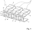
- Figure 1 shows a perspective view of a first embodiment of a spring clamp contact 1 which is essentially formed from a busbar 2 and several, for example three clamp springs 3 as shown.
- the busbar 2 is formed from a material with good electrical conductivity, such as, for example, from a copper sheet. It extends transversely to the direction of extension of the clamping springs 3 and in the rowing direction of the several clamping springs 3. In this way, the electrical conductor clamped to one clamping point of the busbar 2 with a clamping spring 3 can then be clamped to another clamp spring 3 of the spring clamp contact 1 in an electrically conductive manner electrical conductors are connected.
- the clamping springs 3 each have a contact leg 4, a spring bow 5 adjoining the contact leg 4 and a clamping leg 6 adjoining the spring bow 5.
- the clamping legs 6 each have a clamping section 7 at the free end on which a clamping edge is formed.
- associated frame parts 8 are formed for each clamping spring 3, each having two spaced-apart side webs 9a, 9b and an upper cross web 10 connecting the side webs 9a, 9b to one another at the free end.
- the transverse busbar 2 forms a further lower transverse web 11.
- the side webs 9a, 9b and the opposing cross webs 10, 11 create a conductor feed-through opening 12 for the passage of an electrical conductor which is attached to the clamping edge of the clamping section 7 of the associated clamping spring 3 and the contact edge 13 formed on the lower transverse web 11 of the busbar 2 is clamped.
- the clamping edge of the clamping section 7 of the clamping spring 3 and the contact edge 13 of the busbar 2 thus form a clamping point for the electrical conductor to be clamped.
- the frame parts 8 for the clamping springs 3 arranged next to one another are spaced apart from one another, forming an intermediate space 14 between frame parts 8 arranged next to one another.
- the adjacent side webs 9a, 9b of the frame parts 8 lying next to one another are spaced apart from one another.
- a section of an actuating element (not shown) for at least one associated clamping spring 3 can be introduced into this intermediate space 14, so that the space between the clamping springs 3 and in particular the space between the frame parts 8 can be used through the intermediate space 14 to accommodate sections of an actuating lever . This allows a very compact connecting terminal to be built.
- the clamping section 7 of the clamping spring 3 has a smaller width than the adjoining further section of the clamping leg 6 and the spring bow 5.
- the axis of rotation of this actuating lever is then located below the clamping leg 6 and the spring bow 5 in the space between the clamping leg 6 and busbar 2.
- the free end of the contact limb 4 also has a smaller width than the section of the contact limb 4 and the spring bow 5 adjoining the spring bow 5.
- This The reduced width of the contact leg 4 is adapted to the width of the conductor lead-through opening 12 of the frame part 8 in order to enable the contact leg 4 to be hooked into the conductor lead-through opening 2 for contact with the upper transverse web 10.
- Figure 2 omits a side view of the spring clamping contact 1 Figure 1 detect. It becomes clear that the rear free end of the contact leg 4 protrudes through the conductor lead-through opening 12 of the frame part 8 and is hooked into the frame part 8. It can also be seen that the frame part 8 is integrally formed in one piece with the busbar 2 from the same sheet metal part and is bent over from the plane of the busbar adjoining the clamping edge of the clamping spring 3 in the direction of the contact leg 4 of the clamping spring 3 at an angle of approximately 90 ° to 120 ° .
- the clamping leg 6 is bent at an internal angle of approximately 70 ° to 120 ° in the direction of the plane of the busbar 2 on which the clamping edge of the clamping section 7 rests in the illustrated idle state and is almost (+/- 20 °) is perpendicular to this plane. From this strongly bent section standing transversely to the conductor insertion direction, the clamping section 7 is then bent back to the free end to form a clamping edge and is at an acute angle to the aforementioned plane of the busbar 2 electrical conductor can be prevented without prior opening of the terminal point by shifting the clamping leg 6 upwards in the direction of the contact leg 4. Such direct insertion of a multi-wire electrical conductor without prior actuation could lead to the multiple wires of the electrical conductor being fanned out, which are then located in the connection space in an uncontrolled manner.
- Figure 3 omits a side sectional view through the first embodiment of the spring clamp contact Figure 1 and 2 detect. It becomes clear that the contact leg 4 is passed through the conductor lead-through opening 12 with a bent end section 15 and is in contact with the upper transverse web 10. The clamping spring 3 is thus suspended in a stable position in the busbar 2. The opposite end of the U-shaped bent clamping spring 3, ie the clamping section 7 of the clamping leg 4 is bent in the direction of the section of the busbar 2 which extends transversely to the number of clamping springs 3 and adjoins the frame parts 8, the free end of the Clamping section is at an acute angle to this transverse section of the busbar 2.
- An adjoining section of the clamping leg 6 that is approximately transversely to the conductor insertion direction L and the section of the busbar 2 is, however, aligned at an obtuse angle to the transverse section of the busbar 2 in order to prevent a multi-wire electrical conductor from being plugged in directly without prior actuation of the clamping spring 3 .
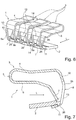
- Figure 4 shows a cross-sectional view of a connecting terminal 16 with an insulating material housing 17.
- the insulating housing 17 is made in two parts and has a main housing part 18 made of insulating material, which is closed with a cover part 20 after an actuating lever 19 and the spring terminal contact 1 have been inserted.
- the main housing part 18 and cover part 20 are locked together in order to mount the actuating lever 19 with a pivot bearing section 21, which has a part-circular periphery, on this part-circular periphery with matching part-circular bearing contours 22 in the insulating material housing 17.
- the pivot bearing section 21 can also be supported on the busbar 2.
- the pivot bearing section 21 has an actuating contour 23 in the form of a V-shaped cutout, which merges into the outer circumference via a curved path.
- the clamping leg 6 of the associated clamping spring 3 rests with a lateral area on this actuating contour 23, so that the clamping leg 6 is displaced away from the transverse section of the busbar 2 in the illustrated open position of the actuating lever 9.
- An electrical conductor can then be introduced via a conductor entry opening 24 in the insulating material housing 17, which is open at the end and opens into the connection space of the spring clamp contact 1. This is then passed over the inclined section of the busbar 2 extending transversely to the clamping springs 3 through the conductor lead-through opening 12 of the associated frame part 8 of the spring clamp contact 1. The free stripped end of an electrical conductor then arrives in a conductor receiving pocket 25, which is located behind the conductor feed-through opening 12 of the frame part 8 in the conductor guide direction L, i.e. in the direction of extension of the conductor insertion opening 24.
- Figure 5 omits the connecting terminal 16 Figure 4 detect when closed.
- the actuating lever 19 is folded down in the direction of the insulating housing 17.
- the actuating contour 23 has rotated here by pivoting the pivot bearing section 21 by approximately 90 °. This makes it possible for the clamping leg 6 to move away from the contact leg 4 downward in the direction of the busbar 2 by the force of the clamping spring 3. In the illustrated closed end position, the clamping leg 6 no longer rests on the actuating section 23, so that the clamping spring 3 can move unimpaired by the actuating lever 19.
- FIG. 6 shows a perspective view of a second embodiment of a spring clamp contact 1 not according to the invention.
- a busbar 2 extends transversely to the direction in which several clamping springs 3 are arranged.
- a retaining lug 26 protrudes from the busbar 2 from the side edge of the busbar 2 in the conductor insertion direction L, that is, in the direction of extension of the contact leg 4 and the clamping leg 6 of the clamping springs 3 .
- a clamping point for clamping an electrical conductor is provided by a clamping edge on the free end of the clamping section 7 of the clamping spring 3 and a contact edge 13 on the associated retaining lug 26.
- An electrical conductor to be clamped is thus pressed by the force of the clamping spring 3 with the clamping edge on the clamping section 7 of the clamping spring 3 against the contact edge 13 on the opposite retaining lug 26.
- the force of the clamping spring 3 is concentrated on a defined, reduced contact area and the surface pressure is thus optimized.
- the frame parts 8 are now integrally formed in one piece with the associated clamping spring 3.
- the frame parts 8 are formed as an extension of the contact leg 4 and are bent from the contact leg 4 in the direction of the opposite, transverse section of the busbar 2.
- the frame parts 8 in turn have side webs 9a, 9b and at the free end a transverse web 11 which connects the side webs 9a, 9b to one another and which engages under the busbar 2.
- the clamping spring 3 is hooked into the busbar 2 and held on the busbar 2 by the force of the clamping spring via the clamping leg 6.
- an upper transverse web 10 is provided for connecting the frame parts 8, so that the transverse webs 10, 11 and the side webs 9a, 9b form a conductor feed-through opening 12 for passing an electrical conductor through.
- Figure 7 omits a side sectional view through the spring terminal contact 1 Figure 6 detect. It becomes clear that the transverse web 11 is folded or bent over at the free end of the frame part 8 and lies under the transverse section of the busbar 2.
- the retaining lug 26 is displaced downward out of the plane of the busbar 2, for example by pressing, in order to form a stop for the lower transverse web 11. In this way, the clamping spring 3 is locked on the busbar 2.
- a contact edge 13 for clamping an electrical conductor is created on the top of the busbar 2, on which the clamping force of the clamping spring 3 is concentrated.
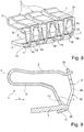
- Figure 8 leaves a perspective view and Figure 9 a side sectional view of a third embodiment of a spring terminal contact 1 can be seen.
- several clamping springs 3 are lined up next to one another and hooked into a busbar 2.
- separate frame parts 8 are provided from the busbar 2 and the clamping spring 3, which frame parts are preferably formed from a sheet metal material.
- the task of the busbar 2 is comparable to the first embodiment.
- the retaining lug 26 is displaced downward relative to the underside of the busbar 2 in order to form a stop for the lower transverse web 11 of the frame part 8.
- no free space with a shoulder for forming a clamping edge 13 is provided.
- the busbar runs obliquely from the upper level, so that a clamping edge 13 is formed in the transition between the upper level of the busbar 2 and the obliquely tapering end.
- the busbar 2 it is also conceivable to use the busbar 2 from the second exemplary embodiment in the present solution.
- the first and second embodiment are combined in such a way that, with the help of the separate frame parts 8, the contact leg 4 of the associated clamping spring 3 is hooked into the upper crossbar 10 and the busbar 2 is hooked into the lower crossbar 11 with the help of the retaining lug 26.
- the frame parts 8 have two spaced-apart side webs 9a, 9b and at the two opposite ends cross webs 10, 11 that connect the side webs 9a, 9b to one another, in order to create a circumferentially closed frame with a conductor opening 12 formed in between.
- the frame parts 8 are arranged at a distance from one another on the busbar 2 with an intermediate space 14. It is irrelevant whether the frame parts are formed in one piece, integrally with the busbar 2 or with an associated clamping spring 3, or are designed as a separate component from the busbar 2 and the clamping springs 3.
- the spring clamp contact 1 and a connecting terminal 16 equipped with such a spring clamp contact 1 can also be designed in two rows. Two parallel conductor connection planes spaced apart from one another are provided in that frame parts 8 extend in opposite directions to one another.
- a double-layer busbar 2 can be provided which has integrally formed frame parts 8 extending in opposite directions.
- separate frame parts can also be accommodated in a space between the double-layer busbar. It is also conceivable, however, for conductor connections to be lined up next to one another with frame parts 8 alternately oriented in opposite directions on a busbar 2.
- a two-row connecting terminal 16 can also be created by having at least one clamping spring 3 above and below the busbar with an orientation rotated by 180 ° to each other and, on the one hand, in the space above and on the other hand in the space below the busbar 2, frame parts 8 on opposite outer edges the busbar 2 are provided.
Landscapes
- Installation Of Bus-Bars (AREA)
- Connections Arranged To Contact A Plurality Of Conductors (AREA)
- Railway Tracks (AREA)
Priority Applications (1)
| Application Number | Priority Date | Filing Date | Title |
|---|---|---|---|
| PL14704143T PL2956993T3 (pl) | 2013-02-13 | 2014-02-12 | Złączka z zaciskiem sprężynowym i zacisk przyłączeniowy dla przewodów elektrycznych |
Applications Claiming Priority (2)
| Application Number | Priority Date | Filing Date | Title |
|---|---|---|---|
| DE202013100635U DE202013100635U1 (de) | 2013-02-13 | 2013-02-13 | Federklemmkontakt und Verbindungsklemme für elektrische Leiter |
| PCT/EP2014/052719 WO2014124961A1 (de) | 2013-02-13 | 2014-02-12 | Federklemmkontakt und verbindungsklemme für elektrische leiter |
Publications (2)
| Publication Number | Publication Date |
|---|---|
| EP2956993A1 EP2956993A1 (de) | 2015-12-23 |
| EP2956993B1 true EP2956993B1 (de) | 2021-04-07 |
Family
ID=48051756
Family Applications (1)
| Application Number | Title | Priority Date | Filing Date |
|---|---|---|---|
| EP14704143.8A Active EP2956993B1 (de) | 2013-02-13 | 2014-02-12 | Federklemmkontakt und verbindungsklemme für elektrische leiter |
Country Status (10)
| Country | Link |
|---|---|
| US (1) | US9502790B2 (ja) |
| EP (1) | EP2956993B1 (ja) |
| JP (1) | JP6400607B2 (ja) |
| KR (1) | KR102145876B1 (ja) |
| CN (1) | CN104995798B (ja) |
| DE (1) | DE202013100635U1 (ja) |
| ES (1) | ES2871850T3 (ja) |
| PL (1) | PL2956993T3 (ja) |
| RU (1) | RU2597003C1 (ja) |
| WO (1) | WO2014124961A1 (ja) |
Cited By (1)
| Publication number | Priority date | Publication date | Assignee | Title |
|---|---|---|---|---|
| DE202023101520U1 (de) | 2023-03-27 | 2024-07-01 | WAGO Verwaltungsgesellschaft mit beschränkter Haftung | Leiteranschlussklemme mit mehreren Federkraftklemmanschlüssen |
Families Citing this family (27)
| Publication number | Priority date | Publication date | Assignee | Title |
|---|---|---|---|---|
| DE102014102517B4 (de) * | 2014-02-26 | 2021-06-10 | Wago Verwaltungsgesellschaft Mbh | Verbindungsklemme und Federkraftklemmkontakt hierzu |
| DE102014103638B4 (de) * | 2014-03-17 | 2016-05-19 | Phoenix Contact Gmbh & Co. Kg | Elektrische Anschlussklemme |
| CN104051869B (zh) | 2014-06-17 | 2016-07-06 | 江门市创艺电器有限公司 | 一种插接式接线端子 |
| DE102015100823B4 (de) * | 2015-01-21 | 2021-12-09 | Phoenix Contact Gmbh & Co. Kg | Elektrische Anschlussklemme |
| CN204558667U (zh) * | 2015-04-11 | 2015-08-12 | 江门市创艺电器有限公司 | 一种接线端子连接器 |
| DE202015105023U1 (de) * | 2015-09-22 | 2016-12-23 | Weidmüller Interface GmbH & Co. KG | Anschlussvorrichtung für Leiter |
| DE102015120002B4 (de) * | 2015-11-18 | 2017-10-19 | Lisa Dräxlmaier GmbH | Verbindungsvorrichtung und Verbindungsverfahren |
| JP2017183023A (ja) * | 2016-03-29 | 2017-10-05 | パナソニックIpマネジメント株式会社 | 端子装置及びそれを備えた配線器具 |
| DE102016111536A1 (de) | 2016-06-23 | 2017-12-28 | Wago Verwaltungsgesellschaft Mbh | Kontakteinsatz einer Federkraftanschlussklemme sowie damit ausgebildete Federkraftanschlussklemme |
| DE102016111627A1 (de) * | 2016-06-24 | 2017-12-28 | Wago Verwaltungsgesellschaft Mbh | Leiteranschlussklemme |
| DE102016116966A1 (de) | 2016-09-09 | 2018-03-15 | Wago Verwaltungsgesellschaft Mbh | Federkraftklemmanschluss sowie Leiteranschlussklemme |
| DE102016122238A1 (de) * | 2016-11-18 | 2018-05-24 | Wago Verwaltungsgesellschaft Mbh | Federklemmkontakt zur Kontaktierung elektrischer Leiter, Leiteranschlussklemme und Verfahren zur Herstellung eines Federklemmkontakts |
| CN113422227A (zh) | 2017-01-06 | 2021-09-21 | 哈勃股份有限公司 | 电插座、电源线连接器、电源线插头和电气布线装置 |
| JP6527905B2 (ja) * | 2017-05-17 | 2019-06-05 | 矢崎総業株式会社 | グリス塗布用接触バネ保持治具 |
| CN107799914B (zh) * | 2017-10-12 | 2023-11-07 | 东莞市美金兴能源有限公司 | 一种线夹 |
| CN108429042A (zh) * | 2018-03-20 | 2018-08-21 | 苏州惠华电子科技有限公司 | 一种紧凑型快速接线连接器 |
| BE1026171B1 (de) * | 2018-04-03 | 2019-10-30 | Phoenix Contact Gmbh & Co Kg | Anschlusseinrichtung zum Anschließen eines Schirmleiters einer elektrischen Leitung an einen Erdungsabschnitt |
| FR3079890B1 (fr) * | 2018-04-04 | 2020-04-03 | A. Raymond Et Cie | Agrafe de fixation pour chassis photovoltaique a montage par insertion puis coulissement dans une fente d’une paroi de support |
| CN108899664A (zh) * | 2018-07-30 | 2018-11-27 | 浙江京红电器有限公司 | 电线接线夹 |
| DE102019108291A1 (de) | 2019-03-29 | 2020-10-01 | Wago Verwaltungsgesellschaft Mbh | Leiteranschlussklemme |
| US11495895B2 (en) | 2019-05-01 | 2022-11-08 | Hubbell Incorporated | Terminations for electrical wiring devices |
| DE202019105009U1 (de) | 2019-09-11 | 2020-12-14 | Wago Verwaltungsgesellschaft Mbh | Leiteranschlussklemme |
| DE102019131653B4 (de) * | 2019-11-22 | 2024-01-18 | Wago Verwaltungsgesellschaft Mbh | Leiteranschlussklemme |
| DE102020104077A1 (de) * | 2020-02-17 | 2021-08-19 | WAGO Verwaltungsgesellschaft mit beschränkter Haftung | Federkraftklemmanschluss |
| USD988266S1 (en) * | 2020-07-23 | 2023-06-06 | Electro Terminal Gmbh & Co Kg | Clamp |
| US11791573B2 (en) | 2021-04-15 | 2023-10-17 | Leviton Manufacturing Co., Inc. | Wire terminals and method of uses |
| KR102649866B1 (ko) * | 2022-08-11 | 2024-03-21 | 주식회사 원익큐엔씨 | 탄성 단자 모듈 및 이를 포함하는 자외선 램프 구조체 |
Citations (1)
| Publication number | Priority date | Publication date | Assignee | Title |
|---|---|---|---|---|
| DE19654611A1 (de) * | 1996-12-20 | 1998-06-25 | Wago Verwaltungs Gmbh | Verbindungsklemme für ein- oder mehrdrähtige elektr. Leiter |
Family Cites Families (47)
| Publication number | Priority date | Publication date | Assignee | Title |
|---|---|---|---|---|
| US3528050A (en) * | 1969-05-02 | 1970-09-08 | Holub Ind Inc | Push-on type grounding clip |
| JPS478986U (ja) * | 1971-02-23 | 1972-10-03 | ||
| JPS60163673U (ja) * | 1984-04-06 | 1985-10-30 | 日本鋼管株式会社 | 電気導体の接続端子 |
| US5046965A (en) * | 1990-05-04 | 1991-09-10 | Utah Medical Products, Inc. | Disposable electrical connector for fetal scalp electrode |
| GB9013869D0 (en) * | 1990-06-21 | 1990-08-15 | Toby Lane Limited | Improvements in or relating to electrical connectors |
| JP3794514B2 (ja) * | 1996-07-31 | 2006-07-05 | ザ ウィタカー コーポレーション | 電気コネクタ |
| DE19641206C2 (de) * | 1996-09-25 | 1999-12-23 | Wago Verwaltungs Gmbh | Anschlußklemme für elektrische Leiter |
| JPH11307146A (ja) * | 1998-04-14 | 1999-11-05 | Whitaker Corp:The | 電気コネクタ |
| DE29915512U1 (de) * | 1999-09-03 | 2001-01-18 | Weidmüller Interface GmbH & Co., 32760 Detmold | Federklemme zum Anschließen elektrischer Leiter |
| ATE217123T1 (de) * | 2000-12-11 | 2002-05-15 | Hager Electro | Verbinder mit einer in einem käfig befindlichen klemmfeder und einer auf die klemmfeder bezogenen platte |
| JP4208130B2 (ja) * | 2002-06-20 | 2009-01-14 | タイコ エレクトロニクス アンプ ゲゼルシャフト ミット ベシュレンクテル ハウツンク | プラグ型電気コネクタ |
| DE10237701B4 (de) | 2002-08-16 | 2010-09-16 | Wago Verwaltungsgesellschaft Mbh | Verbindungsklemme für ein-, mehrdrähtige, insbesondere feindrähtige, elektrische Leiter |
| DE10239273A1 (de) * | 2002-08-22 | 2004-03-04 | Wago Verwaltungsgesellschaft Mbh | Federkraftklemmanschluß für einen elektrischen Leiter |
| RU27744U1 (ru) * | 2002-10-18 | 2003-02-10 | Закрытое акционерное общество "Дальневосточная технология" | Соединительный элемент |
| DE20313855U1 (de) | 2003-09-06 | 2005-01-05 | Weidmüller Interface GmbH & Co. KG | Anschlußvorrichtung zum Direktsteckanschluß von Leiterenden |
| US6893286B2 (en) | 2003-09-06 | 2005-05-17 | Weidmüller Interface GmbH & Co. KG | Connector apparatus adapted for the direct plug-in connection of conductors |
| JP4089578B2 (ja) * | 2003-09-25 | 2008-05-28 | 松下電工株式会社 | 配線器具 |
| DE102004008447A1 (de) * | 2004-02-19 | 2005-09-08 | Abb Patent Gmbh | Federkraftklemme |
| JP2005235711A (ja) * | 2004-02-23 | 2005-09-02 | Nichifu Co Ltd | 電線接続器 |
| DE102004046471B3 (de) * | 2004-09-23 | 2006-02-09 | Phoenix Contact Gmbh & Co. Kg | Elektrische Anschluß- oder Verbindungsklemme |
| FR2876226B1 (fr) * | 2004-10-01 | 2007-01-19 | Abb Entrelec Soc Par Actions S | Organe de connexion electrique et mecanique d'un organe de raccordement electrique |
| DE102005045596B3 (de) * | 2005-09-23 | 2007-06-21 | Siemens Ag | Feder-Steckklemme |
| DE102006019150B4 (de) * | 2006-04-21 | 2011-06-09 | Wago Verwaltungsgesellschaft Mbh | Elektrische Verbindungsklemme |
| DE102007017593B4 (de) | 2006-04-28 | 2011-07-21 | WAGO Verwaltungsgesellschaft mbH, 32423 | Elektrische Anschluß- und Verbindungsklemme |
| DE102007024690B4 (de) * | 2007-05-25 | 2009-06-04 | Phoenix Contact Gmbh & Co. Kg | Elektrische Anschluß- oder Verbindungsklemme |
| US7507106B2 (en) * | 2007-06-14 | 2009-03-24 | Ideal Industries, Inc. | Push-in wire connector with improved busbar |
| PT2096714E (pt) * | 2008-01-31 | 2010-05-21 | Bticino Spa | Dispositivo de ligação eléctrica com mola de contacto comandada por uma alavanca que possui uma abertura de entrada para o terminal de um cabo eléctrico |
| DE102008024366B4 (de) * | 2008-05-20 | 2010-11-25 | Phoenix Contact Gmbh & Co. Kg | Durchführungsklemme |
| US7618279B1 (en) * | 2008-06-26 | 2009-11-17 | Thomas & Betts International, Inc. | One-piece push-in electrical contact terminal |
| DE102009004513A1 (de) | 2009-01-09 | 2010-07-22 | Phoenix Contact Gmbh & Co. Kg | Klemmfeder für eine Federkraftklemme |
| CN102598421B (zh) * | 2009-09-29 | 2015-06-24 | 理想工业公司 | 单件式导电夹 |
| CN201639002U (zh) * | 2009-12-23 | 2010-11-17 | 富士康(昆山)电脑接插件有限公司 | 电连接器及其端子 |
| CN201655989U (zh) * | 2010-04-12 | 2010-11-24 | 上海航天科工电器研究院有限公司 | 导线快速锁紧结构 |
| DE102010024809B4 (de) | 2010-06-23 | 2013-07-18 | Wago Verwaltungsgesellschaft Mbh | Anschlussklemme |
| DE102010025930B4 (de) | 2010-07-02 | 2019-10-17 | Phoenix Contact Gmbh & Co. Kg | Anschlussklemme |
| DE102010051899B4 (de) * | 2010-11-22 | 2015-03-26 | Wago Verwaltungsgesellschaft Mbh | Elektrisches Klemmenbauelement |
| US8353716B2 (en) * | 2010-12-14 | 2013-01-15 | Ideal Industries, Inc. | Terminal structures for wiring devices |
| DE102011011080B4 (de) * | 2011-02-11 | 2013-04-11 | Wago Verwaltungsgesellschaft Mbh | Federklemmanschluss und Leiteranschlusseinheit |
| RU2467437C1 (ru) * | 2011-05-04 | 2012-11-20 | Федеральное государственное образовательное учреждение высшего профессионального образования "Кубанский государственный аграрный университет" | Соединительный зажим для электрических проводников |
| DE102011108828B4 (de) * | 2011-07-29 | 2013-06-27 | Phoenix Contact Gmbh & Co. Kg | Elektrische Anschlussvorrichtung |
| DE202011104318U1 (de) | 2011-08-15 | 2012-08-17 | Hellermanntyton Gmbh | Verbindungsklemme |
| DE102011054425A1 (de) | 2011-10-12 | 2013-04-18 | Phoenix Contact Gmbh & Co. Kg | Federkörper einer Federkraftklemme und Federkraftklemmanordnung |
| DE102011056410B4 (de) | 2011-12-14 | 2013-06-27 | Wago Verwaltungsgesellschaft Mbh | Anschlussklemme |
| CN202474257U (zh) * | 2011-12-22 | 2012-10-03 | 泰科电子(上海)有限公司 | 弹性夹持件、接触轨组件及具有该组件的光伏组件接线盒 |
| DE102012005465B3 (de) | 2012-03-20 | 2013-05-08 | Wieland Electric Gmbh | Federklemme |
| CN102832465B (zh) * | 2012-08-21 | 2016-04-20 | 江门市创艺电器有限公司 | 一种led用一体式连接器 |
| DE102013101409B4 (de) * | 2013-02-13 | 2022-01-20 | Wago Verwaltungsgesellschaft Mbh | Leiteranschlussklemme |
-
2013
- 2013-02-13 DE DE202013100635U patent/DE202013100635U1/de not_active Expired - Lifetime
-
2014
- 2014-02-12 KR KR1020157021752A patent/KR102145876B1/ko active IP Right Grant
- 2014-02-12 JP JP2015557409A patent/JP6400607B2/ja active Active
- 2014-02-12 PL PL14704143T patent/PL2956993T3/pl unknown
- 2014-02-12 WO PCT/EP2014/052719 patent/WO2014124961A1/de active Application Filing
- 2014-02-12 CN CN201480008490.8A patent/CN104995798B/zh active Active
- 2014-02-12 RU RU2015133914/07A patent/RU2597003C1/ru active
- 2014-02-12 ES ES14704143T patent/ES2871850T3/es active Active
- 2014-02-12 US US14/767,719 patent/US9502790B2/en active Active
- 2014-02-12 EP EP14704143.8A patent/EP2956993B1/de active Active
Patent Citations (2)
| Publication number | Priority date | Publication date | Assignee | Title |
|---|---|---|---|---|
| DE19654611A1 (de) * | 1996-12-20 | 1998-06-25 | Wago Verwaltungs Gmbh | Verbindungsklemme für ein- oder mehrdrähtige elektr. Leiter |
| US5975940A (en) * | 1996-12-20 | 1999-11-02 | Wago Verwaltungsgesellschaft Mbh | Self-clamping connectors for single-wired and multi-wire conductors |
Cited By (1)
| Publication number | Priority date | Publication date | Assignee | Title |
|---|---|---|---|---|
| DE202023101520U1 (de) | 2023-03-27 | 2024-07-01 | WAGO Verwaltungsgesellschaft mit beschränkter Haftung | Leiteranschlussklemme mit mehreren Federkraftklemmanschlüssen |
Also Published As
| Publication number | Publication date |
|---|---|
| JP6400607B2 (ja) | 2018-10-03 |
| WO2014124961A1 (de) | 2014-08-21 |
| CN104995798B (zh) | 2017-11-14 |
| EP2956993A1 (de) | 2015-12-23 |
| JP2016507147A (ja) | 2016-03-07 |
| KR102145876B1 (ko) | 2020-08-20 |
| RU2597003C1 (ru) | 2016-09-10 |
| KR20150116853A (ko) | 2015-10-16 |
| DE202013100635U1 (de) | 2013-03-04 |
| PL2956993T3 (pl) | 2021-10-11 |
| CN104995798A (zh) | 2015-10-21 |
| US9502790B2 (en) | 2016-11-22 |
| US20150372402A1 (en) | 2015-12-24 |
| ES2871850T3 (es) | 2021-11-02 |
Similar Documents
| Publication | Publication Date | Title |
|---|---|---|
| EP2956993B1 (de) | Federklemmkontakt und verbindungsklemme für elektrische leiter | |
| EP3324490B1 (de) | Federklemmkontakt zur kontaktierung elektrischer leiter, leiteranschlussklemme und verfahren zur herstellung eines federklemmkontakts | |
| EP3298659B1 (de) | Leiteranschlussklemme | |
| EP3111513B1 (de) | Verbindungsklemme und federkraftklemmkontakt hierzu | |
| EP2917971B1 (de) | Federkraftklemmanschluss und elektrisches gerät hiermit | |
| EP2956992B1 (de) | Leiteranschlussklemme | |
| EP3125372B2 (de) | Anschlussklemme | |
| EP2956990B1 (de) | Federkraftklemmelement und verbindungsklemme | |
| DE102018117508B4 (de) | Leiteranschlussklemme | |
| EP3787121A1 (de) | Leiteranschlussklemme | |
| EP3507866B1 (de) | Leiteranschlussklemme | |
| DE102011056043B4 (de) | Stromschienenabgriffelement | |
| DE102015118032B4 (de) | Leiteranschlussklemme | |
| DE102013104394A1 (de) | Leiteranschlussklemme | |
| EP3145031B1 (de) | Leiteranschlussklemme | |
| DE202016100798U1 (de) | Federanschlussklemme | |
| DE102015112433B4 (de) | Leiteranschlussklemme | |
| EP3038213B1 (de) | Leiteranschlussklemme zum anklemmen wenigstens eines elektrischen leiters | |
| WO2020259926A1 (de) | Elektrische anschlussklemme | |
| EP3849018B1 (de) | Leiteranschlussklemme | |
| EP4320688A1 (de) | Verbindungsklemme zum verbinden wenigstens zweier elektrischer leiter | |
| EP3888190B1 (de) | Anschlusselement | |
| EP4331057A1 (de) | Elektrisches leiteranschlusselement mit kontaktfeder |
Legal Events
| Date | Code | Title | Description |
|---|---|---|---|
| PUAI | Public reference made under article 153(3) epc to a published international application that has entered the european phase |
Free format text: ORIGINAL CODE: 0009012 |
|
| 17P | Request for examination filed |
Effective date: 20150909 |
|
| AK | Designated contracting states |
Kind code of ref document: A1 Designated state(s): AL AT BE BG CH CY CZ DE DK EE ES FI FR GB GR HR HU IE IS IT LI LT LU LV MC MK MT NL NO PL PT RO RS SE SI SK SM TR |
|
| AX | Request for extension of the european patent |
Extension state: BA ME |
|
| DAX | Request for extension of the european patent (deleted) | ||
| STAA | Information on the status of an ep patent application or granted ep patent |
Free format text: STATUS: EXAMINATION IS IN PROGRESS |
|
| 17Q | First examination report despatched |
Effective date: 20170315 |
|
| GRAP | Despatch of communication of intention to grant a patent |
Free format text: ORIGINAL CODE: EPIDOSNIGR1 |
|
| STAA | Information on the status of an ep patent application or granted ep patent |
Free format text: STATUS: GRANT OF PATENT IS INTENDED |
|
| INTG | Intention to grant announced |
Effective date: 20201029 |
|
| GRAS | Grant fee paid |
Free format text: ORIGINAL CODE: EPIDOSNIGR3 |
|
| GRAA | (expected) grant |
Free format text: ORIGINAL CODE: 0009210 |
|
| STAA | Information on the status of an ep patent application or granted ep patent |
Free format text: STATUS: THE PATENT HAS BEEN GRANTED |
|
| AK | Designated contracting states |
Kind code of ref document: B1 Designated state(s): AL AT BE BG CH CY CZ DE DK EE ES FI FR GB GR HR HU IE IS IT LI LT LU LV MC MK MT NL NO PL PT RO RS SE SI SK SM TR |
|
| REG | Reference to a national code |
Ref country code: GB Ref legal event code: FG4D Free format text: NOT ENGLISH |
|
| REG | Reference to a national code |
Ref country code: AT Ref legal event code: REF Ref document number: 1380885 Country of ref document: AT Kind code of ref document: T Effective date: 20210415 Ref country code: CH Ref legal event code: EP |
|
| REG | Reference to a national code |
Ref country code: DE Ref legal event code: R096 Ref document number: 502014015459 Country of ref document: DE |
|
| REG | Reference to a national code |
Ref country code: IE Ref legal event code: FG4D Free format text: LANGUAGE OF EP DOCUMENT: GERMAN |
|
| REG | Reference to a national code |
Ref country code: LT Ref legal event code: MG9D |
|
| REG | Reference to a national code |
Ref country code: NL Ref legal event code: MP Effective date: 20210407 |
|
| PG25 | Lapsed in a contracting state [announced via postgrant information from national office to epo] |
Ref country code: HR Free format text: LAPSE BECAUSE OF FAILURE TO SUBMIT A TRANSLATION OF THE DESCRIPTION OR TO PAY THE FEE WITHIN THE PRESCRIBED TIME-LIMIT Effective date: 20210407 Ref country code: BG Free format text: LAPSE BECAUSE OF FAILURE TO SUBMIT A TRANSLATION OF THE DESCRIPTION OR TO PAY THE FEE WITHIN THE PRESCRIBED TIME-LIMIT Effective date: 20210707 Ref country code: FI Free format text: LAPSE BECAUSE OF FAILURE TO SUBMIT A TRANSLATION OF THE DESCRIPTION OR TO PAY THE FEE WITHIN THE PRESCRIBED TIME-LIMIT Effective date: 20210407 Ref country code: NL Free format text: LAPSE BECAUSE OF FAILURE TO SUBMIT A TRANSLATION OF THE DESCRIPTION OR TO PAY THE FEE WITHIN THE PRESCRIBED TIME-LIMIT Effective date: 20210407 Ref country code: LT Free format text: LAPSE BECAUSE OF FAILURE TO SUBMIT A TRANSLATION OF THE DESCRIPTION OR TO PAY THE FEE WITHIN THE PRESCRIBED TIME-LIMIT Effective date: 20210407 |
|
| REG | Reference to a national code |
Ref country code: ES Ref legal event code: FG2A Ref document number: 2871850 Country of ref document: ES Kind code of ref document: T3 Effective date: 20211102 |
|
| PG25 | Lapsed in a contracting state [announced via postgrant information from national office to epo] |
Ref country code: GR Free format text: LAPSE BECAUSE OF FAILURE TO SUBMIT A TRANSLATION OF THE DESCRIPTION OR TO PAY THE FEE WITHIN THE PRESCRIBED TIME-LIMIT Effective date: 20210708 Ref country code: IS Free format text: LAPSE BECAUSE OF FAILURE TO SUBMIT A TRANSLATION OF THE DESCRIPTION OR TO PAY THE FEE WITHIN THE PRESCRIBED TIME-LIMIT Effective date: 20210807 Ref country code: LV Free format text: LAPSE BECAUSE OF FAILURE TO SUBMIT A TRANSLATION OF THE DESCRIPTION OR TO PAY THE FEE WITHIN THE PRESCRIBED TIME-LIMIT Effective date: 20210407 Ref country code: PT Free format text: LAPSE BECAUSE OF FAILURE TO SUBMIT A TRANSLATION OF THE DESCRIPTION OR TO PAY THE FEE WITHIN THE PRESCRIBED TIME-LIMIT Effective date: 20210809 Ref country code: NO Free format text: LAPSE BECAUSE OF FAILURE TO SUBMIT A TRANSLATION OF THE DESCRIPTION OR TO PAY THE FEE WITHIN THE PRESCRIBED TIME-LIMIT Effective date: 20210707 Ref country code: SE Free format text: LAPSE BECAUSE OF FAILURE TO SUBMIT A TRANSLATION OF THE DESCRIPTION OR TO PAY THE FEE WITHIN THE PRESCRIBED TIME-LIMIT Effective date: 20210407 Ref country code: RS Free format text: LAPSE BECAUSE OF FAILURE TO SUBMIT A TRANSLATION OF THE DESCRIPTION OR TO PAY THE FEE WITHIN THE PRESCRIBED TIME-LIMIT Effective date: 20210407 |
|
| REG | Reference to a national code |
Ref country code: DE Ref legal event code: R097 Ref document number: 502014015459 Country of ref document: DE |
|
| PG25 | Lapsed in a contracting state [announced via postgrant information from national office to epo] |
Ref country code: DK Free format text: LAPSE BECAUSE OF FAILURE TO SUBMIT A TRANSLATION OF THE DESCRIPTION OR TO PAY THE FEE WITHIN THE PRESCRIBED TIME-LIMIT Effective date: 20210407 Ref country code: CZ Free format text: LAPSE BECAUSE OF FAILURE TO SUBMIT A TRANSLATION OF THE DESCRIPTION OR TO PAY THE FEE WITHIN THE PRESCRIBED TIME-LIMIT Effective date: 20210407 Ref country code: EE Free format text: LAPSE BECAUSE OF FAILURE TO SUBMIT A TRANSLATION OF THE DESCRIPTION OR TO PAY THE FEE WITHIN THE PRESCRIBED TIME-LIMIT Effective date: 20210407 Ref country code: SK Free format text: LAPSE BECAUSE OF FAILURE TO SUBMIT A TRANSLATION OF THE DESCRIPTION OR TO PAY THE FEE WITHIN THE PRESCRIBED TIME-LIMIT Effective date: 20210407 Ref country code: SM Free format text: LAPSE BECAUSE OF FAILURE TO SUBMIT A TRANSLATION OF THE DESCRIPTION OR TO PAY THE FEE WITHIN THE PRESCRIBED TIME-LIMIT Effective date: 20210407 Ref country code: RO Free format text: LAPSE BECAUSE OF FAILURE TO SUBMIT A TRANSLATION OF THE DESCRIPTION OR TO PAY THE FEE WITHIN THE PRESCRIBED TIME-LIMIT Effective date: 20210407 |
|
| PLBE | No opposition filed within time limit |
Free format text: ORIGINAL CODE: 0009261 |
|
| STAA | Information on the status of an ep patent application or granted ep patent |
Free format text: STATUS: NO OPPOSITION FILED WITHIN TIME LIMIT |
|
| 26N | No opposition filed |
Effective date: 20220110 |
|
| PG25 | Lapsed in a contracting state [announced via postgrant information from national office to epo] |
Ref country code: IS Free format text: LAPSE BECAUSE OF FAILURE TO SUBMIT A TRANSLATION OF THE DESCRIPTION OR TO PAY THE FEE WITHIN THE PRESCRIBED TIME-LIMIT Effective date: 20210807 Ref country code: AL Free format text: LAPSE BECAUSE OF FAILURE TO SUBMIT A TRANSLATION OF THE DESCRIPTION OR TO PAY THE FEE WITHIN THE PRESCRIBED TIME-LIMIT Effective date: 20210407 |
|
| PG25 | Lapsed in a contracting state [announced via postgrant information from national office to epo] |
Ref country code: MC Free format text: LAPSE BECAUSE OF FAILURE TO SUBMIT A TRANSLATION OF THE DESCRIPTION OR TO PAY THE FEE WITHIN THE PRESCRIBED TIME-LIMIT Effective date: 20210407 |
|
| REG | Reference to a national code |
Ref country code: BE Ref legal event code: MM Effective date: 20220228 |
|
| PG25 | Lapsed in a contracting state [announced via postgrant information from national office to epo] |
Ref country code: LU Free format text: LAPSE BECAUSE OF NON-PAYMENT OF DUE FEES Effective date: 20220212 |
|
| PG25 | Lapsed in a contracting state [announced via postgrant information from national office to epo] |
Ref country code: IE Free format text: LAPSE BECAUSE OF NON-PAYMENT OF DUE FEES Effective date: 20220212 |
|
| PG25 | Lapsed in a contracting state [announced via postgrant information from national office to epo] |
Ref country code: BE Free format text: LAPSE BECAUSE OF NON-PAYMENT OF DUE FEES Effective date: 20220228 |
|
| REG | Reference to a national code |
Ref country code: DE Ref legal event code: R082 Ref document number: 502014015459 Country of ref document: DE Representative=s name: MEISSNER BOLTE PATENTANWAELTE RECHTSANWAELTE P, DE |
|
| P01 | Opt-out of the competence of the unified patent court (upc) registered |
Effective date: 20230516 |
|
| PG25 | Lapsed in a contracting state [announced via postgrant information from national office to epo] |
Ref country code: HU Free format text: LAPSE BECAUSE OF FAILURE TO SUBMIT A TRANSLATION OF THE DESCRIPTION OR TO PAY THE FEE WITHIN THE PRESCRIBED TIME-LIMIT; INVALID AB INITIO Effective date: 20140212 |
|
| PGFP | Annual fee paid to national office [announced via postgrant information from national office to epo] |
Ref country code: ES Payment date: 20240308 Year of fee payment: 11 |
|
| PGFP | Annual fee paid to national office [announced via postgrant information from national office to epo] |
Ref country code: AT Payment date: 20240220 Year of fee payment: 11 |
|
| PG25 | Lapsed in a contracting state [announced via postgrant information from national office to epo] |
Ref country code: MK Free format text: LAPSE BECAUSE OF FAILURE TO SUBMIT A TRANSLATION OF THE DESCRIPTION OR TO PAY THE FEE WITHIN THE PRESCRIBED TIME-LIMIT Effective date: 20210407 Ref country code: CY Free format text: LAPSE BECAUSE OF FAILURE TO SUBMIT A TRANSLATION OF THE DESCRIPTION OR TO PAY THE FEE WITHIN THE PRESCRIBED TIME-LIMIT Effective date: 20210407 |
|
| PGFP | Annual fee paid to national office [announced via postgrant information from national office to epo] |
Ref country code: DE Payment date: 20240228 Year of fee payment: 11 Ref country code: GB Payment date: 20240220 Year of fee payment: 11 Ref country code: CH Payment date: 20240301 Year of fee payment: 11 |
|
| PGFP | Annual fee paid to national office [announced via postgrant information from national office to epo] |
Ref country code: PL Payment date: 20240201 Year of fee payment: 11 Ref country code: IT Payment date: 20240222 Year of fee payment: 11 Ref country code: FR Payment date: 20240226 Year of fee payment: 11 |
|
| PG25 | Lapsed in a contracting state [announced via postgrant information from national office to epo] |
Ref country code: TR Free format text: LAPSE BECAUSE OF FAILURE TO SUBMIT A TRANSLATION OF THE DESCRIPTION OR TO PAY THE FEE WITHIN THE PRESCRIBED TIME-LIMIT Effective date: 20210407 |