EP2956277B1 - Device for guiding at least one line of a joint arm robot, and joint arm robot - Google Patents
Device for guiding at least one line of a joint arm robot, and joint arm robot Download PDFInfo
- Publication number
- EP2956277B1 EP2956277B1 EP14704756.7A EP14704756A EP2956277B1 EP 2956277 B1 EP2956277 B1 EP 2956277B1 EP 14704756 A EP14704756 A EP 14704756A EP 2956277 B1 EP2956277 B1 EP 2956277B1
- Authority
- EP
- European Patent Office
- Prior art keywords
- guiding
- fixing
- return
- housing
- line
- Prior art date
- Legal status (The legal status is an assumption and is not a legal conclusion. Google has not performed a legal analysis and makes no representation as to the accuracy of the status listed.)
- Active
Links
- 230000007246 mechanism Effects 0.000 claims description 29
- 238000006073 displacement reaction Methods 0.000 description 4
- 230000001681 protective effect Effects 0.000 description 4
- 238000005096 rolling process Methods 0.000 description 3
- 238000003466 welding Methods 0.000 description 3
- 230000005540 biological transmission Effects 0.000 description 2
- 238000003754 machining Methods 0.000 description 2
- 238000000926 separation method Methods 0.000 description 2
- 230000005483 Hooke's law Effects 0.000 description 1
- 230000002411 adverse Effects 0.000 description 1
- 230000005611 electricity Effects 0.000 description 1
- 238000005516 engineering process Methods 0.000 description 1
- 230000007613 environmental effect Effects 0.000 description 1
- 239000012530 fluid Substances 0.000 description 1
- 239000007789 gas Substances 0.000 description 1
- 239000007788 liquid Substances 0.000 description 1
- 230000036316 preload Effects 0.000 description 1
Images


Classifications
-
- B—PERFORMING OPERATIONS; TRANSPORTING
- B25—HAND TOOLS; PORTABLE POWER-DRIVEN TOOLS; MANIPULATORS
- B25J—MANIPULATORS; CHAMBERS PROVIDED WITH MANIPULATION DEVICES
- B25J19/00—Accessories fitted to manipulators, e.g. for monitoring, for viewing; Safety devices combined with or specially adapted for use in connection with manipulators
- B25J19/0025—Means for supplying energy to the end effector
-
- H—ELECTRICITY
- H02—GENERATION; CONVERSION OR DISTRIBUTION OF ELECTRIC POWER
- H02G—INSTALLATION OF ELECTRIC CABLES OR LINES, OR OF COMBINED OPTICAL AND ELECTRIC CABLES OR LINES
- H02G11/00—Arrangements of electric cables or lines between relatively-movable parts
- H02G11/003—Arrangements of electric cables or lines between relatively-movable parts using gravity-loaded or spring-loaded loop
-
- H—ELECTRICITY
- H02—GENERATION; CONVERSION OR DISTRIBUTION OF ELECTRIC POWER
- H02G—INSTALLATION OF ELECTRIC CABLES OR LINES, OR OF COMBINED OPTICAL AND ELECTRIC CABLES OR LINES
- H02G3/00—Installations of electric cables or lines or protective tubing therefor in or on buildings, equivalent structures or vehicles
- H02G3/30—Installations of cables or lines on walls, floors or ceilings
- H02G3/32—Installations of cables or lines on walls, floors or ceilings using mounting clamps
-
- Y—GENERAL TAGGING OF NEW TECHNOLOGICAL DEVELOPMENTS; GENERAL TAGGING OF CROSS-SECTIONAL TECHNOLOGIES SPANNING OVER SEVERAL SECTIONS OF THE IPC; TECHNICAL SUBJECTS COVERED BY FORMER USPC CROSS-REFERENCE ART COLLECTIONS [XRACs] AND DIGESTS
- Y10—TECHNICAL SUBJECTS COVERED BY FORMER USPC
- Y10T—TECHNICAL SUBJECTS COVERED BY FORMER US CLASSIFICATION
- Y10T74/00—Machine element or mechanism
- Y10T74/20—Control lever and linkage systems
- Y10T74/20207—Multiple controlling elements for single controlled element
- Y10T74/20305—Robotic arm
- Y10T74/20311—Robotic arm including power cable or connector
Definitions
- the invention relates to a device for guiding at least one line of a Gelenkarmroboters, in particular for guiding a hose assembly of an industrial robot with the features of the preamble of claim 1.
- the invention further relates to a Gelenkarmroboter with such a device.
- Such a device is for example from the JP 2012 161903 A refer to.
- a plurality of individual lines for supplying a tool arranged on the robot hand, for example a welding tool, are fed to the foremost robotic arm, also referred to as a robotic hand.
- the individual cables are, for example, electrical supply cables, electrical control cables, data cables and media guides for gases or liquids.
- These individual cables are combined in a so-called hose package and are held in a tubular protective jacket.
- Such a hose package is on the one hand because of the relative movements of the robot arms to each other and in particular because of the often adverse environmental conditions (high temperatures, aggressive media, such as welding spatter, etc.) exposed to high loads.
- a line guide device is usually used, which is designed such that a compensating movement of the hose assembly is made possible in a relative movement between two robot arms.
- a routing device in an industrial robot is for example from the DE 201 13 742 U1 refer to.
- a device which has a guide unit and a slide element, which is mounted relative to the guide unit at this longitudinally displaceable by means of rods between a first and a second position. Furthermore, designed as a helical spring elastic return unit is provided, which exerts an elastic restoring force on the sliding element.
- From the JP 2012 161903 A is to take a device in which within a support member a longitudinally displaceable on a guide rail held slide element is arranged. On the slider element, a clamp is attached, which protrudes through an upper slot-shaped longitudinal opening of the support member and holds a hose package. The entire device is also rotatably arranged around a robot arm, so that both a rotational movement and a longitudinal movement is possible.
- the present invention seeks to provide an improved device for guiding at least one line of a Gelenkarmroboters, in particular a hose assembly of an industrial robot and such Gelenkarmroboter, especially industrial robots.
- the object is achieved by a device having the features of claim 1.
- the device has a housed in a housing return mechanism for exerting an elastic restoring force on at least one line.
- the housing has two opposing slot-shaped openings, via which a fastening element for fastening the at least one line, in particular a hose package, is connected to a slide element arranged within the housing.
- the fastening element has a bracket with two opposite bracket arms, each of which extends into the housing via the two openings, wherein the fastening element is displaceable on or within these openings.
- the housing comprises as a bottom floor plate and a housing cover, which completely covers the mounted on the bottom plate return mechanism. The entire return mechanism is therefore covered by the housing cover.
- the bracket preferably engages over the housing cover in the manner of a U- or C-arm, wherein in its center, that is on top of the housing cover, expediently a clamp for fixing the at least one line, in particular the hose package is arranged.
- the return mechanism preferably has a guide unit and a slide element, which is held on the guide unit displaceable between a first and a second position. With the slider element in particular the fastening element for fixing the line is connected. Furthermore, a particular elastic restoring unit is arranged, which is arranged between the guide unit and the slider element acting, that exerts a restoring force on the slider element.
- the elastic return unit comprises a deflecting element, which is preferably held on the guide unit, and a bendable, strand-shaped connecting element, which is guided around the deflecting element and connected to the slide element. About this bendable, strand-shaped connecting element, the elastic restoring force is exerted on the slider element.
- Biegeflexibles, strand-shaped connecting element are initially understood to mean all elements which allow a deflection around the deflecting element, in particular by 180 °, and which are also suitable for transmitting the required forces in an industrial robot.
- This strand-shaped connecting element is in particular rope, belt or belt-like elements.
- elastic return unit is meant a unit or assembly which exerts an elastic restoring force on the slider element.
- Under slide element is generally understood a guide or sliding element which guides the fastener for the line along a predetermined path and with the return unit for transmitting the restoring force is connected to the fastener.
- the slider element is designed in particular in the manner of a guided carriage.
- the restoring force is - depending on the application - preferably in the range of 40N to 250N and is preferably at least approximately constant over the entire adjustment.
- the connecting element itself is elastic and exerts the elastic restoring force.
- the connecting element is thus elastically extensible overall. It is designed, for example, in the manner of a rubber band. In particular, it has a linear voltage characteristic, that is, the restoring force exerted increases in proportion to the elongation.
- the deflecting element is preferably a deflection roller which is mounted in order to keep the frictional forces for the deflection of the connecting element as low as possible.
- At least one further deflection element in particular likewise a deflection roller, is arranged, wherein the connection element is guided around the plurality of deflection elements. Due to the multiple deflection, the transmission ratio between the adjustment of the at least one line and the adjustment of the connecting element is further increased.
- another bendable, strand-shaped connecting element is arranged parallel to the first connecting element. This measure also serves to improve the adjustment of the restoring force.
- the two connecting elements are preferably arranged on both sides of the slide element, so that a uniform, torque-free transmission of the restoring force is realized on the slide element.
- the slider element itself is expediently mounted longitudinally displaceably in a guide rail.
- the guide rail is part of the guide unit and connected thereto or formed on this.
- the slider element is mounted on a rolling bearing unit.
- This has expediently a cage with rolling bearings, wherein the cage is guided longitudinally displaceable within the guide rail and the slide element is in turn guided longitudinally displaceable in or on the cage.
- the guide rail is arranged in particular centrally on the guide unit, and there are exactly two connecting elements arranged, which extend parallel to the central guide rail. Each connecting element is assigned at least one deflection roller.
- the connecting element is generally fastened at one end to a fixing point, in particular to the guide unit.
- a fixing point in particular to the guide unit.
- the fixing point is expediently adjustable for adjusting the bias of the elastic return unit.
- different mounting options for the fixing element are expediently prepared on the guide unit, for example in the form of a plurality of individual boreholes or in the form of a slot, within which the fixing element is adjustable etc.
- the guide unit further expediently has a base plate to which the guide rail is fastened.
- the bottom plate is further preferably designed as a mounting plate for mounting on a robot arm. As such, it expediently has boreholes, via which a fastening is made possible indirectly or else directly on a robot arm.
- a guide clamp is attached to the guide unit expediently, in comparison to the slide element stationary. By this guide clamp the line, so the hose package, guided in the mounted state slidably.
- the connecting element is connected to an elastic return element, via which the restoring force is exerted.
- This restoring element is preferably a spiral spring unit. Also in this case is extended by the extended path of the connecting element of the adjustment of this coil spring unit in a suitable manner.
- the connecting element itself in this case has no or only a slight stretchability. It is for example designed as a rope.
- a non-circular or eccentrically mounted rotary element is arranged, around which the connecting element is guided and fastened therewith, so that upon a movement of the connecting element this leads to a rotary movement of the rotary element.
- this leads to a change in a lever arm between a point of engagement of the connecting element and a rotational axis of the rotary member.
- the change is set such that a restoring force acting on the slide element is at least substantially constant, regardless of the current position of the slide element.
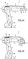
- the industrial robot 1 To supply the machining tool 6 with electricity and / or fluids and / or data signals, the industrial robot 1 has a supply line package 7, which is guided along the robot arm 2 and from there to the base 8. In the area of the robot arm 2, the supply line package 7 is guided in a protective tube.
- the supply line package 7 together with the protective tube is also referred to below as a tube package 9.
- a separation point for the supply line package 7 is arranged in the region of the second articulated connection and the hose assembly 9 is guided as an exchangeable wear unit up to this separation point.
- a pulling movement is exerted on the hose package in a rotational movement about the third hinge axis R3.
- the hose package In the reverse movement back to the starting position according to the Fig. 1 the hose package must be pulled back to its original position.
- a device 10 for guiding and retrieving the hose assembly 9 is fastened on the robot arm 2 in the region of the second articulated connection R2.
- this device 10 is a mounting bracket 14 belonging, in which the hose assembly 9 is held, in particular form-fitting, so that a force exerted by the device restoring force is transmitted to the hose assembly 9.
- the robot hand 3 oriented end of the hose assembly 9 is additionally fixed by a further mounting bracket 15, so that the hose assembly 9 is held taut between the two mounting clamps 14,15.
- the hose package 9 extends between these two mounting clamps 14,15, so ends at this.
- the single ones Lines or the supply line package 7 exits at these positions from the protective tube.
- a first embodiment of the device 10 is in the Fig. 2 to 6 shown.
- the device 10 comprises a housing 16, which has a housing cover 18 and a bottom plate 20.
- the housing 16 has in the exemplary embodiment two opposite longitudinal slots 22 which extend in the longitudinal direction z of the device.
- the longitudinal direction z at the same time also corresponds to the longitudinal direction of the hose package 9.
- the mounting bracket 14 is mounted on an approximately U- or C-arm-shaped bracket 24, the bracket 24 extends along the top of the housing cover 18 and has two bracket arms 26 which are connected in the embodiment with laterally projecting side flanges of a slider element 28. As will be explained in more detail later, the bracket 24 is slidably mounted together with the fastening point 14 along the longitudinal slots 22. The bracket 24 forms in the embodiment together with the mounting clamp 14, a fastener on which the hose assembly 9 is held.
- a guide clamp 30 is arranged, with a guide insert 32 which widens approximately trumpet-shaped in both directions. Within this guide insert 32, the hose assembly 9 is slidably guided in the mounted state. In contrast, the hose package 9 is fixed in place in the mounting clamp 14, in particular by a positive connection.
- the mounting clamp 14 is formed in particular with an inner annular groove into which a corresponding annular web of the hose assembly 9 engages.
- the mounting clamp 14 and / or the guide clamp 30 are formed in a manner not shown here in such a way that the hose pack 9 can perform a tilting movement relative to the longitudinal direction 23. Both clamps 14, 30 are as shown in the figures of two via connecting elements (screws) interconnected Half shells formed. As a result, a simple replacement of the hose package 9 is possible.
- a return mechanism 40 which comprises the already mentioned slide element 28, a guide rail 42, first guide rollers 44 and an elastic, cable-like connecting element 46.
- the connecting element 46 is, for example, an elastic cable, an elastic band or another elastic, flexurally flexible element.
- the one end of the connecting element 46 is fastened to a fixing element 48, which is held fixedly on the bottom plate 20, which is also part of the return mechanism 40.
- the other end of the connecting element 46 is fastened to the slide element 28.
- the connecting element 46 is previously guided around the first guide roller 44, which is fastened to the base plate 20 substantially at the opposite end.
- a total of two connecting elements 46 are arranged, which are each arranged and formed symmetrically with respect to a central longitudinal axis of the device 10, so that a uniform force on the slider element 28 results.
- the ends of the two connecting elements 46 engage on laterally projecting arms of the slide element 28.
- the two connecting elements 46 extend on both sides of the centrally arranged guide rail 42.
- the slider element 28 is mounted within the guide rail 42 by means of a sliding element 50, in particular ball-bearing.
- the sliding member 50 is slidably disposed within a cage 52, wherein the cage 52 a plurality of rolling elements, in particular balls 54, receives.
- the cage 52 itself together with the balls 54 is in turn displaceably mounted within the guide rail 42.
- the cage 52 extends approximately over half the length of the guide rail 42.
- the manner of a Nutsteins trained sliding element 50 is part of the slider element 28.
- the slider element 28 is plate-shaped. The sliding element 50 is preferably fastened to this plate via a plurality of screws.
- the mounting plate 20 laterally downwardly bent tabs, which form approximately a step, with end tabs 56 to which the bracket 24 is attached.
- the tabs 26 are guided down approximately at the level of the bottom plate 20 and are guided through the longitudinal slots 22 to the outside.
- the longitudinal slots 22 are formed by recesses in the bottom plate 20.
- the guide clamp 30 is connected to the bottom plate 20 in the end region of the bottom plate 20, in which the fixing element 48 is fixed.
- the bottom plate 20 a plurality of mounting holes 58 are formed, via which an attachment of the entire device 10 takes place on the industrial robot 1. Due to the multiplicity of fastening holes 58, the device 10 can be adapted to different industrial robots 1 with different hole patterns or arranged at different positions.
- the bottom plate 20 therefore also defines a mounting plate.
- Fig. 7 shows an alternative embodiment of the return mechanism 40, which is similar to the functional principle of the first embodiment variant.
- a second guide roller 60 is fixed to the bottom plate 20, so that the two guide rollers 44, 60 are disposed at opposite ends of the bottom plate 20 and the elastic connecting member 46 is deflected twice.
- the central placement of two edge-side guide rails 42 are now formed so that the bottom plate 20 together with these guide rails 42 in cross-section form an approximately U-shaped guide unit.
- the slide element 28 is mounted on both sides in the two guide rails 42.
- Fig. 8 shows, in particular, a storage by means of rollers 62, which run in the guide rail 42 along.
- the guide rail 42 is in this case formed approximately as a C-profile and there are a total of three rollers 62 are arranged, which are supported on the one hand upwards and downwards to the C-profile.
- the longitudinal direction corresponds to the z-direction shown in the figure.
- the mounting clamps 14 of all embodiments described here are preferably tilted slightly in the x and / or y direction.
- Fig. 9 is a modified embodiment of the return mechanism 40 according to the Fig. 7 shown.
- the bottom plate 20 In contrast to the embodiment according to the Fig. 7 is now the bottom plate 20 and thus formed the guide unit formed from the bottom plate 20 with the guide rails 42 curved, so that therefore a displacement of the mounting clamp 14 along a curved path runs.
- the pulleys 44, 60 are for example hinged to the bottom plate 20.
- FIG. 10 Yet another embodiment of the return mechanism 40 shown. Again, this shows again edge-arranged guide rails 42 with the mounted on the rollers 62 slide element 28. While in the previous embodiments, the connecting element 46 itself was designed to be elastic, it is now formed as a non-elastic, non-stretchable connecting element 64.
- the one end of the connecting element 64 is attached to an elastic return element 66.
- the restoring element 66 also comprises a rotatably mounted rotary element 70, which is rotatable about an eccentric axis 72.
- the eccentric shaft 72 defines at the same time the central axis of the coil spring 68.
- the connecting element 64 is guided around the rotary member 70 in a corresponding groove and fixed to the rotary member 70.
- a lever arm is formed so far, so that via the connecting element 64, a torque is transmitted to the coil spring 68.
- the spiral spring 68 is attached at its one end to the axis 72 and at its other end to the rotary member 70.
- the configuration of the rotary member 70 is formed such that upon a displacement of the slide member 28, the restoring force exerted on this and thus on the mounting clamp 14 remains constant. An increase in the elastic restoring force of the spiral spring 68 is therefore compensated by a reduction of, for example, the lever arm via the rotary member 70. Conveniently, therefore, over the entire displacement of the mounting clamp 14, the restoring force acting on these constant.
- the return mechanism with the two outer guide rails 42 is also a variant similar to the in Fig. 2 with the housing 16 allows.
- the return mechanisms 40 of all embodiments can therefore be integrated into a housing 16. It can also be further return mechanisms 40, for example, without deflecting elements 44, 60 and, for example, arranged with coil springs.
- the longitudinal slot 22 would not be arranged laterally but on the upper side of the housing cover 18, so that the fastening clip 14 extends above the housing cover 18.
- the length and thus the force of the bias voltage can be readily adjusted, without this being determined by the dimensions of the device 10.
- Fig. 11 This situation will be in Fig. 11 represented, in which the restoring force F against an extension in the longitudinal direction z shown for different situations is.
- the position z 0 (crossing point of the two axes of the coordinate system) defines a biasing force F 2 .
- the restoring force of the elastic return unit is linear, so that with increasing expansion in the longitudinal direction z, the force F linear increases in accordance with a predetermined by the elastic return unit spring rate.
- the maximum extension length is in the Fig. 11 Denoted, so the extension length between the retracted and the extended position. In the extended position, a restoring force F 1 is achieved.
- the length adjustment for in particular the connecting element 46, 66 is shown, which is given by the deflection rollers 44, 60 and an adjustment of the fixing element 48.
- the length of the connecting element 46, 66 in the non-extended basic position is in the Fig. 5 shown as bias length I.
- bias length I With only a small pretensioning length I ', a comparatively high spring rate, ie a high pitch, is required in order to achieve the desired pretensioning F 2 .
- the connecting element 46, 66 can be adjusted in a suitable manner, a defined bias with a biasing force F 2 even with a short overall length of the device 10.
- the Connecting element 46 is formed in particular itself as an elastic element for exerting the restoring force.
Description
Die Erfindung betrifft eine Vorrichtung zur Führung von zumindest einer Leitung eines Gelenkarmroboters, insbesondere zur Führung eines Schlauchpaketes eines Industrieroboters mit den Merkmalen des Oberbegriffs des Anspruchs 1. Die Erfindung betrifft weiterhin einen Gelenkarmroboter mit einer solchen Vorrichtung.The invention relates to a device for guiding at least one line of a Gelenkarmroboters, in particular for guiding a hose assembly of an industrial robot with the features of the preamble of claim 1. The invention further relates to a Gelenkarmroboter with such a device.
Eine solche Vorrichtung ist beispielsweise aus der
Bei den heute üblicherweise eingesetzten mehrachsigen Industrierobotern werden dem vordersten, auch als Roboterhand bezeichneten Roboterarm mehrere Einzelleitungen zur Versorgung eines an der Roboterhand angeordneten Werkzeugs, beispielsweise ein Schweißwerkzeug, zugeführt. Die Einzelleitungen sind beispielsweise elektrische Versorgungskabel, elektrische Steuerkabel, Datenkabel sowie Medienführungen für Gase oder Flüssigkeiten. Diese Einzelleitungen werden in einem so genannten Schlauchpaket zusammengefasst und sind in einem schlauchförmigen Schutzmantel gehalten. Ein derartiges Schlauchpaket ist zum einen wegen der Relativbewegungen der Roboterarme zueinander und insbesondere auch wegen der oftmals widrigen Umgebungsbedingungen (hohe Temperaturen, aggressive Medien, wie Schweißspritzer, etc.) hohen Belastungen ausgesetzt.In the multiaxis industrial robots commonly used today, a plurality of individual lines for supplying a tool arranged on the robot hand, for example a welding tool, are fed to the foremost robotic arm, also referred to as a robotic hand. The individual cables are, for example, electrical supply cables, electrical control cables, data cables and media guides for gases or liquids. These individual cables are combined in a so-called hose package and are held in a tubular protective jacket. Such a hose package is on the one hand because of the relative movements of the robot arms to each other and in particular because of the often adverse environmental conditions (high temperatures, aggressive media, such as welding spatter, etc.) exposed to high loads.
Um eine zuverlässige Führung des Schlauchpakets zu ermöglichen, wird üblicherweise eine Leitungsführungseinrichtung eingesetzt, welche derart beschaffen ist, dass eine Ausgleichsbewegung des Schlauchpakets bei einer Relativbewegung zwischen zwei Roboterarmen ermöglicht ist. Eine Leitungsführungseinrichtung bei einem Industrieroboter ist beispielsweise aus der
In der
Bei derartigen Vorrichtungen wird häufig aus Platzgründen eine möglichst kleinbauende Ausgestaltung angestrebt, gleichzeitig sollen jedoch möglichst große Ausgleichslängen verwirklicht werden. Um diese zunächst gegenläufigen Anforderungen zu verwirklichen, ist beispielsweise aus der
Bei kleinbauenden Vorrichtungen besteht weiterhin das Problem, dass eine ausreichend hohe Rückstellkraft insbesondere auch in der eingefahrenen Endposition ausgeübt werden muss, um ein sicheres Zurückholen des Schlauchpaktes in diese eingefahrene Endposition zu gewährleisten. Dies bedeutet, dass die elastische Rückstelleinheit mit einer vergleichsweise großen Vorspannung eingestellt werden muss, welche die Rückstellkraft an der eingefahrenen Position bestimmt. Die elastischen Rückstelleinheiten, wie beispielsweise Schraubenfedern, unterliegen dabei typischerweise dem Hookeschen Gesetz, die Rückstellkraft steigt daher linear mit dem Weg. Bei kurzen Baulängen und einer erforderlichen hohen Rückstellkraft an der eingefahrenen Position bedeutet dies, dass eine vergleichsweise hohe Federhärte erforderlich ist, was dazu führt, dass die Kraft beim Ausfahren in unerwünschter Weise sehr stark zunimmt. Aus der
Ausgehend hiervon liegt der Erfindung die Aufgabe zugrunde, eine verbesserte Vorrichtung zur Führung von zumindest einer Leitung eines Gelenkarmroboters, insbesondere eines Schlauchpakets eines Industrieroboters sowie einen solchen Gelenkarmroboter, insbesondere Industrieroboter, anzugeben.
Die Aufgabe wird erfindungsgemäß gelöst durch eine Vorrichtung mit den Merkmalen des Anspruchs 1.Proceeding from this, the present invention seeks to provide an improved device for guiding at least one line of a Gelenkarmroboters, in particular a hose assembly of an industrial robot and such Gelenkarmroboter, especially industrial robots.
The object is achieved by a device having the features of claim 1.
Die Vorrichtung weist eine in einem Gehäuse eingehauste Rückstellmechanik zur Ausübung einer elastischen Rückstellkraft auf zumindest eine Leitung auf. Das Gehäuse weist dabei zwei gegenüberliegende schlitzförmige Öffnungen auf, über die ein Befestigungselement zur Befestigung der zumindest einen Leitung, insbesondere eines Schlauchpakets, mit einem innerhalb des Gehäuses angeordneten Schieberelement verbunden ist. Das Befestigungselement weist einen Bügel mit zwei gegenüberliegenden Bügelarmen auf, die jeweils über die beiden Öffnungen in das Gehäuse hinein reichen, wobei das Befestigungselement an oder innerhalb dieser Öffnungen verschieblich ist.The device has a housed in a housing return mechanism for exerting an elastic restoring force on at least one line. The housing has two opposing slot-shaped openings, via which a fastening element for fastening the at least one line, in particular a hose package, is connected to a slide element arranged within the housing. The fastening element has a bracket with two opposite bracket arms, each of which extends into the housing via the two openings, wherein the fastening element is displaceable on or within these openings.
Dadurch ist insgesamt eine sehr kompakte Ausgestaltung ermöglicht bei gleichzeitigem Schutz der Rückstellmechanik.As a result, a very compact overall design is possible with simultaneous protection of the return mechanism.
Zudem wird eine zuverlässige Führung des Schlauchpakets erzielt, insbesondere ohne dass Verkippmomente in die Rückstellmechanik eingeleitet werden.In addition, a reliable guidance of the hose package is achieved, in particular without tilting moments are introduced into the return mechanism.
Im Unterschied zu den Ausführungsvarianten wie sie beispielsweise aus der
Zweckdienlicherweise umfasst das Gehäuse als Boden eine Bodenplatte sowie einen Gehäusedeckel, welcher die auf der Bodenplatte angebrachte Rückstellmechanik vollständig überdeckt. Die gesamte Rückstellmechanik ist daher von dem Gehäusedeckel überdeckt.Conveniently, the housing comprises as a bottom floor plate and a housing cover, which completely covers the mounted on the bottom plate return mechanism. The entire return mechanism is therefore covered by the housing cover.
Der Bügel übergreift dabei vorzugsweise den Gehäusedeckel in etwa nach Art eines U- oder C-Arms, wobei in seiner Mitte, also oben auf dem Gehäusedeckel, zweckdienlicherweise eine Schelle zur Fixierung der zumindest einen Leitung, insbesondere des Schlauchpakets angeordnet ist.The bracket preferably engages over the housing cover in the manner of a U- or C-arm, wherein in its center, that is on top of the housing cover, expediently a clamp for fixing the at least one line, in particular the hose package is arranged.
Die Rückstellmechanik weist vorzugsweise eine Führungseinheit und ein Schieberelement auf, das an der Führungseinheit verschieblich zwischen einer ersten und einer zweiten Position gehalten ist. Mit dem Schieberelement ist insbesondere das Befestigungselement zur Fixierung der Leitung verbunden. Weiterhin ist eine insbesondere elastische Rückstelleinheit angeordnet, die zwischen der Führungseinheit und dem Schieberelement wirkend angeordnet ist, also eine Rückstellkraft auf das Schieberelement ausübt. Die elastische Rückstelleinheit umfasst ein vorzugsweise an der Führungseinheit gehaltenes Umlenkelement sowie ein biegeflexibles, strangförmiges Verbindungselement, welches um das Umlenkelement geführt und mit dem Schieberelement verbunden ist. Über dieses biegeflexible, strangförmige Verbindungselement wird die elastische Rückstellkraft auf das Schieberelement ausgeübt.The return mechanism preferably has a guide unit and a slide element, which is held on the guide unit displaceable between a first and a second position. With the slider element in particular the fastening element for fixing the line is connected. Furthermore, a particular elastic restoring unit is arranged, which is arranged between the guide unit and the slider element acting, that exerts a restoring force on the slider element. The elastic return unit comprises a deflecting element, which is preferably held on the guide unit, and a bendable, strand-shaped connecting element, which is guided around the deflecting element and connected to the slide element. About this bendable, strand-shaped connecting element, the elastic restoring force is exerted on the slider element.
Unter biegeflexibles, strangförmiges Verbindungselement werden zunächst alle Elemente verstanden, die ein Umlenken um das Umlenkelement, insbesondere um 180°, erlauben und die zudem zur Übertragung der erforderlichen Kräfte bei einem Industrieroboter geeignet sind. Bei diesem strangförmigen Verbindungselement handelt es sich dabei insbesondere um seil-, band- oder auch riemenartige Elemente. Unter elastische Rückstelleinheit wird eine Einheit oder Baugruppe verstanden, welche eine elastische Rückstellkraft auf das Schieberelement ausübt. Unter Schieberelement wird allgemein ein Führungs- oder Gleitelement verstanden, welches das Befestigungselement für die Leitung entlang einer vorgegebenen Bahn führt und mit der Rückstelleinheit zur Übertragung der Rückstellkraft auf das Befestigungselement verbunden ist. Das Schieberelement ist insbesondere nach Art eines geführten Schlittens ausgebildet.Biegeflexibles, strand-shaped connecting element are initially understood to mean all elements which allow a deflection around the deflecting element, in particular by 180 °, and which are also suitable for transmitting the required forces in an industrial robot. This strand-shaped connecting element is in particular rope, belt or belt-like elements. By elastic return unit is meant a unit or assembly which exerts an elastic restoring force on the slider element. Under slide element is generally understood a guide or sliding element which guides the fastener for the line along a predetermined path and with the return unit for transmitting the restoring force is connected to the fastener. The slider element is designed in particular in the manner of a guided carriage.
Aufgrund der Anordnung des biegeflexiblen, strangförmigen Verbindungselements und dessen Umlenkung wird bei kompakter Bauweise eine geeignete Einstellung der Rückstellkraft ermöglicht. Aufgrund der Umlenkung wird der Verstellweg für die elastische Rückstelleinheit insgesamt vergrößert, sodass also eine Art Übersetzung verwirklicht ist, zwischen der tatsächlichen Verstellbewegung des Schlauchpakets und der Verstellbewegung des elastischen Rückstellelements. Hierdurch wird die Einstellung einer ausreichenden Rückstellkraft einerseits in der zurückgezogenen Position und gleichzeitig eine nicht zu hohe Rückstellkraft in der ausgezogenen Position problemlos ermöglicht. Es kann daher eine geeignete Federhärte der elastischen Rückstelleinheit ausgewählt werden. Diese ist im Vergleich zu einer übersetzungsfreien Ausführungsvariante daher insgesamt geringer. Die Rückstellkraft liegt dabei - je nach Anwendungsfall - bevorzugt im Bereich von 40N bis 250N und ist über den gesamten Verstellweg vorzugsweise zumindest annähernd konstant.Due to the arrangement of the flexurally flexible, strand-shaped connecting element and its deflection, a suitable adjustment of the restoring force is made possible in a compact design. Due to the deflection of the adjustment for the elastic return unit is increased overall, so so a kind of translation is realized between the actual adjustment of the hose assembly and the adjustment of the elastic return element. As a result, the setting of a sufficient restoring force on the one hand in the retracted position and at the same time a not too high restoring force in the extended position easily possible. Therefore, a suitable spring hardness of the elastic return unit can be selected. This is therefore lower overall compared to a translation-free variant. The restoring force is - depending on the application - preferably in the range of 40N to 250N and is preferably at least approximately constant over the entire adjustment.
In zweckdienlicher Weiterbildung ist das Verbindungselement selbst elastisch und übt die elastische Rückstellkraft aus. Das Verbindungselement ist also insgesamt elastisch dehnbar. Es ist dabei beispielsweise nach Art eines Gummibandes ausgebildet. Es weist insbesondere eine lineare Spannungscharakteristik auf, das heißt die ausgeübte Rückstellkraft nimmt proportional zur Dehnung zu.In an expedient development, the connecting element itself is elastic and exerts the elastic restoring force. The connecting element is thus elastically extensible overall. It is designed, for example, in the manner of a rubber band. In particular, it has a linear voltage characteristic, that is, the restoring force exerted increases in proportion to the elongation.
Bei dem Umlenkelement handelt es sich dabei vorzugsweise um eine Umlenkrolle, welche gelagert ist, um die Reibungskräfte für die Umlenkung des Verbindungselements möglichst gering zu halten.The deflecting element is preferably a deflection roller which is mounted in order to keep the frictional forces for the deflection of the connecting element as low as possible.
In bevorzugter Weiterbildung ist zumindest ein weiteres Umlenkelement, insbesondere ebenfalls eine Umlenkrolle, angeordnet, wobei das Verbindungselement um die mehreren Umlenkelemente geführt ist. Durch die mehrfache Umlenkung wird das Übersetzungsverhältnis zwischen dem Verstellweg der zumindest einen Leitung und dem Verstellweg des Verbindungselements weiter erhöht.In a preferred development, at least one further deflection element, in particular likewise a deflection roller, is arranged, wherein the connection element is guided around the plurality of deflection elements. Due to the multiple deflection, the transmission ratio between the adjustment of the at least one line and the adjustment of the connecting element is further increased.
Zweckdienlicherweise ist ein weiteres biegeflexibles, strangförmiges Verbindungselement parallel zum ersten Verbindungselement angeordnet. Auch diese Maßnahme dient für eine verbesserte Anpassung der Rückstellkraft. Bei einer zentralen Führung des Schieberelements sind die beiden Verbindungselemente vorzugsweise beidseitig zum Schieberelement angeordnet, sodass eine gleichmäßige, drehmomentfreie Übertragung der Rückstellkraft auf das Schieberelement verwirklicht ist.Conveniently, another bendable, strand-shaped connecting element is arranged parallel to the first connecting element. This measure also serves to improve the adjustment of the restoring force. In a central guide of the slide element, the two connecting elements are preferably arranged on both sides of the slide element, so that a uniform, torque-free transmission of the restoring force is realized on the slide element.
Das Schieberelement selbst ist zweckdienlicherweise in einer Führungsschiene längsverschieblich gelagert. Die Führungsschiene ist dabei ein Teil der Führungseinheit und mit dieser verbunden oder an dieser ausgeformt. Für eine möglichst reibungsarme Führung ist das Schieberelement dabei über eine Wälzlagereinheit gelagert. Diese weist hierzu zweckdienlicherweise einen Käfig mit Wälzlagern auf, wobei der Käfig innerhalb der Führungsschiene längsverschieblich geführt ist und das Schieberelement wiederum im oder am Käfig längsverschieblich geführt ist. Die Führungsschiene ist dabei insbesondere mittig auf der Führungseinheit angeordnet, und es sind genau zwei Verbindungselemente angeordnet, die parallel zu der mittigen Führungsschiene verlaufen. Jedem Verbindungselement ist dabei zumindest eine Umlenkrolle zugeordnet.The slider element itself is expediently mounted longitudinally displaceably in a guide rail. The guide rail is part of the guide unit and connected thereto or formed on this. For a possible low-friction guidance, the slider element is mounted on a rolling bearing unit. This has expediently a cage with rolling bearings, wherein the cage is guided longitudinally displaceable within the guide rail and the slide element is in turn guided longitudinally displaceable in or on the cage. The guide rail is arranged in particular centrally on the guide unit, and there are exactly two connecting elements arranged, which extend parallel to the central guide rail. Each connecting element is assigned at least one deflection roller.
Das Verbindungselement ist generell mit einem Ende an einem Fixierpunkt, insbesondere an der Führungseinheit, befestigt. Über die Positionierung des Fixierpunktes und/oder der Wahl der Federrate der elastischen Rückstelleinheit lässt sich die Vorspannung geeignet für den jeweiligen Anwendungsfall einstellen. Der Fixierpunkt ist dabei zweckdienlicherweise zur Einstellung der Vorspannung der elastischen Rückstelleinheit verstellbar. Dadurch besteht die Möglichkeit vor Ort, also bei der Montage am Industrieroboter, eine bestmögliche Einstellung zu erzielen. Hierzu sind zweckdienlicherweise an der Führungseinheit unterschiedliche Befestigungsmöglichkeiten für das Fixierelement vorbereitet, beispielsweise in Form von mehreren einzelnen Bohrlöchern oder in Form eines Langlochs, innerhalb dessen das Fixierelement verstellbar ist etc.The connecting element is generally fastened at one end to a fixing point, in particular to the guide unit. About the positioning of the fixing point and / or the choice of the spring rate of the elastic return unit, the bias can be suitably set for the particular application. The fixing point is expediently adjustable for adjusting the bias of the elastic return unit. As a result, it is possible to achieve the best possible setting on site, ie during assembly on the industrial robot. For this purpose, different mounting options for the fixing element are expediently prepared on the guide unit, for example in the form of a plurality of individual boreholes or in the form of a slot, within which the fixing element is adjustable etc.
Die Führungseinheit weist weiterhin zweckdienlicherweise eine Bodenplatte auf, an der die Führungsschiene befestigt ist. Die Bodenplatte ist weiterhin vorzugsweise als Montageplatte zur Montage auf einem Roboterarm ausgebildet ist. Als solche weist sie zweckdienlicherweise Bohrlöcher auf, über die eine Befestigung mittelbar oder auch unmittelbar an einem Roboterarm ermöglicht ist.The guide unit further expediently has a base plate to which the guide rail is fastened. The bottom plate is further preferably designed as a mounting plate for mounting on a robot arm. As such, it expediently has boreholes, via which a fastening is made possible indirectly or else directly on a robot arm.
Weiterhin ist an der Führungseinheit zweckdienlicherweise eine Führungsschelle befestigt, und zwar im Vergleich zu dem Schieberelement ortsfest. Durch diese Führungsschelle ist die Leitung, also das Schlauchpaket, im montierten Zustand gleitverschieblich geführt.Furthermore, a guide clamp is attached to the guide unit expediently, in comparison to the slide element stationary. By this guide clamp the line, so the hose package, guided in the mounted state slidably.
Gemäß einer alternativen Ausführungsvariante ist das Verbindungselement mit einem elastischen Rückstellelement verbunden, über welches die Rückstellkraft ausgeübt wird. Bei diesem Rückstellelement handelt es sich vorzugsweise um eine Spiralfedereinheit. Auch in diesem Fall wird durch den verlängerten Weg des Verbindungselements der Verstellweg dieser Spiralfedereinheit in geeigneter Weise verlängert. Das Verbindungselement selbst weist in diesem Fall keine oder nur eine geringfügige Dehnbarkeit auf. Es ist beispielsweise als ein Seil ausgebildet.According to an alternative embodiment, the connecting element is connected to an elastic return element, via which the restoring force is exerted. This restoring element is preferably a spiral spring unit. Also in this case is extended by the extended path of the connecting element of the adjustment of this coil spring unit in a suitable manner. The connecting element itself in this case has no or only a slight stretchability. It is for example designed as a rope.
In zweckdienlicher Weiterbildung ist ein unrundes oder exzentrisch gelagertes Drehelement angeordnet, um das das Verbindungselement geführt und mit diesem befestigt ist, sodass bei einer Bewegung des Verbindungselements dies zu einer Drehbewegung des Drehelements führt. Durch dessen unrunde Ausführung oder durch seine exzentrische Lagerung führt dies zu einer Veränderung eines Hebelarms zwischen einem Angriffspunkt des Verbindungselements und einer Drehachse des Drehelements. Die Veränderung ist dabei derart eingestellt, dass eine auf das Schieberelement wirkende Rückstellkraft zumindest weitgehend konstant ist, unabhängig von der aktuellen Position des Schieberelements.In an expedient development, a non-circular or eccentrically mounted rotary element is arranged, around which the connecting element is guided and fastened therewith, so that upon a movement of the connecting element this leads to a rotary movement of the rotary element. By its non-circular design or by its eccentric bearing, this leads to a change in a lever arm between a point of engagement of the connecting element and a rotational axis of the rotary member. The change is set such that a restoring force acting on the slide element is at least substantially constant, regardless of the current position of the slide element.
Gemäß einer bevorzugten Ausgestaltung ist die Führungseinheit weiterhin gekrümmt ausgebildet. Das gesamte Schlauchpaket wird daher mithilfe der Vorrichtung entlang einer vorgegebenen gekrümmten Bewegungsbahn entlang geführt. Dies ist in einigen Anwendungsgebieten beispielsweise in der Medizintechnik von besonderem Vorteil, bei denen das Schlauchpaket in definierter Weise entlang einer gekrümmten Bahn geführt werden soll.
Insbesondere bei einer derartigen Ausgestaltung ist das Umlenkelement gelenkig beispielsweise über ein Kugelgelenk an der Führungseinheit gelagert. Dadurch stellt sich das Umlenkelement mit seiner Orientierung optimal auf die jeweiligen Gegebenheiten der Führung des Verbindungselements ein.
Die Aufgabe wird weiterhin gelöst durch einen Gelenkarmroboter mit einer derartigen Vorrichtung. Die Vorrichtung ist dabei bei einem mehrachsigen Industrieroboter insbesondere auf einem Roboterarm nachfolgend zu der so genannten Achse 3 in Richtung zu einer Roboterhand befestigt und zweckdienlicherweise im hinteren Bereich des Roboterarms, also nahe an der Achse 3.
Ausführungsbeispiele der Erfindung werden nachfolgend anhand der Figuren näher erläutert. Diese zeigen:
- Fig. 1A
- in schematischer Darstellung einen Industrieroboter mit einer Vorrichtung zur Führung eines Schlauchpakets, wobei sich das Schlauchpaket in einer zurückgefahrenen Ausgangsposition befindet,
- Fig. 1B
- eine schematische Darstellung des Industrieroboters gemäß
Fig. 1a , wobei sich das Schlauchpaket in einer vollständig ausgefahrenen Position befindet, - Fig. 2
- eine perspektivische Darstellung einer Vorrichtung zur Führung eines Schlauchpakets gemäß eines Ausführungsbeispiels der Erfindung,
- Fig. 3
- eine erste Ausführungsvariante einer in perspektivischer Darstellung der in
Fig. 2 dargestellten Vorrichtung, - Fig. 4
- eine Seitenansicht der in
Fig. 3 dargestellten Rückstellmechanik, - Fig. 5
- eine Aufsicht auf die in
Fig. 2 dargestellte Rückstellmechanik, - Fig. 6
- eine Aufsicht auf eine Führungsschiene der Rückstellmechanik,
- Fig. 7
- eine perspektivische Aufsicht auf eine zweite Ausführungsvariante einer Rückstellmechanik,
- Fig. 8
- eine ausschnittsweise Darstellung einer Ausführungsvariante einer Führungsschiene der Rückstellmechanik,
- Fig. 9
- eine dritte Ausführungsvariante einer Rückstellmechanik in perspektivischer Darstellung,
- Fig. 10
- eine vierte Ausführungsvariante einer Rückstellmechanik sowie
- Fig. 11
- eine Grafik zur Illustration des Verlaufs der Rückstellkraft.
In den
In particular, in such an embodiment, the deflecting element is articulated, for example via a ball joint mounted on the guide unit. As a result, the deflection element optimally adjusts with its orientation to the particular conditions of the guidance of the connecting element.
The object is further achieved by a Gelenkarmroboter with such a device. In the case of a multiaxial industrial robot, in particular on a robot arm, the device is fastened subsequently to the so-called
Embodiments of the invention will be explained in more detail with reference to FIGS. These show:
- Fig. 1A
- a schematic representation of an industrial robot with a device for guiding a hose package, wherein the hose package is in a retracted starting position,
- Fig. 1B
- a schematic representation of the industrial robot according to
Fig. 1a with the hose package in a fully extended position, - Fig. 2
- a perspective view of an apparatus for guiding a hose package according to an embodiment of the invention,
- Fig. 3
- a first embodiment of a perspective view of the in
Fig. 2 illustrated device, - Fig. 4
- a side view of in
Fig. 3 shown return mechanism, - Fig. 5
- a supervision of the in
Fig. 2 shown return mechanism, - Fig. 6
- a view of a guide rail of the return mechanism,
- Fig. 7
- a perspective view of a second embodiment of a return mechanism,
- Fig. 8
- a fragmentary view of a variant of a guide rail of the return mechanism,
- Fig. 9
- a third embodiment of a return mechanism in perspective,
- Fig. 10
- a fourth embodiment of a return mechanism and
- Fig. 11
- a graphic illustrating the course of the restoring force.
In the
Zur Versorgung des Bearbeitungswerkzeugs 6 mit Elektrizität und/oder Fluiden und/oder Datensignalen weist der Industrieroboter 1 ein Versorgungsleitungspaket 7 auf, welches am Roboterarm 2 entlanggeführt und von dort mit der Basis 8 verbunden ist. Im Bereich des Roboterarms 2 ist das Versorgungsleitungspaket 7 in einem Schutzschlauch geführt. Das Versorgungsleitungspaket 7 gemeinsam mit dem Schutzschlauch wird nachfolgend auch als Schlauchpaket 9 bezeichnet. Häufig ist im Bereich der zweiten Gelenkverbindung eine Trennstelle für das Versorgungsleitungspaket 7 angeordnet und das Schlauchpaket 9 ist als austauschbare Verschleißeinheit bis zu dieser Trennstelle geführt.To supply the
Wie man der
Hierzu ist im Bereich der zweiten Gelenkverbindung R2 auf dem Roboterarm 2 eine Vorrichtung 10 zur Führung und zur Zurückholung des Schlauchpakets 9 befestigt. In den
An seinem vorderen, zur Roboterhand 3 orientierten Ende ist das Schlauchpaket 9 zusätzlich über eine weitere Befestigungsschelle 15 fixiert, so dass das Schlauchpaket 9 zwischen den beiden Befestigungsschellen 14,15 gespannt gehalten ist. Im Ausführungsbeispiel erstreckt sich das Schlauchpaket 9 zwischen diese beiden Befestigungsschellen 14,15, endet also an diesen. Die einzelnen Leitungen bzw. das Versorgungsleitungspaket 7 tritt an diesen Positionen aus dem Schutzschlauch aus.At its front, the
Eine erste Ausführungsvariante der Vorrichtung 10 ist in den
Die Vorrichtung 10 umfasst eine Gehäuse 16, welches einen Gehäusedeckel 18 sowie eine Bodenplatte 20 aufweist. Das Gehäuse 16 weist im Ausführungsbeispiel zwei gegenüberliegende Längsschlitze 22 auf, die sich in Längsrichtung z der Vorrichtung erstrecken. Die Längsrichtung z entspricht zugleich auch der Längsrichtung des Schlauchpakets 9.The
Die Befestigungsschelle 14 ist auf einem etwa U- oder C-armförmigen Bügel 24 befestigt, der Bügel 24 verläuft dabei entlang der Oberseite des Gehäusedeckels 18 und weist zwei Bügelarme 26 auf, die im Ausführungsbeispiel mit seitlich hervorstehenden Seitenflanschen eines Schieberelements 28 verbunden sind. Wie später noch näher erläutert wird, ist der Bügel 24 zusammen mit der Befestigungsstelle 14 entlang der Längsschlitze 22 verschieblich gelagert. Der Bügel 24 bildet im Ausführungsbeispiel zusammen mit der Befestigungsschelle 14 ein Befestigungselement, an dem das Schlauchpaket 9 gehalten ist.The mounting
Am der Befestigungsschelle 14 gegenüberliegenden Ende der Vorrichtung 10 ist eine Führungsschelle 30 angeordnet, mit einem Führungseinsatz 32, der sich in beide Richtungen etwa trompetenförmig erweitert. Innerhalb dieses Führungseinsatzes 32 ist im montierten Zustand das Schlauchpaket 9 gleitverschieblich geführt. Demgegenüber ist das Schlauchpaket 9 in der Befestigungsschelle 14 ortsfest fixiert, insbesondere durch einen Formschluss. Hierzu ist die Befestigungsschelle 14 insbesondere mit einer inneren Ringnut ausgebildet, in die ein entsprechender Ringsteg des Schlauchpakets 9 eingreift. Die Befestigungsschelle 14 und/oder die Führungsschelle 30 sind in hier nicht näher dargestellter Variante derart ausgebildet, dass das Schlauchpaket 9 eine Verkippbewegung relativ zur Längsrichtung 23 ausführen kann. Beide Schellen 14, 30 sind wie aus den Figuren ersichtlich aus zwei über Verbindungselemente (Schrauben) miteinander verbundene Halbschalen ausgebildet. Hierdurch ist ein einfaches Austauschen des Schlauchpakets 9 ermöglicht.At the end of the
Im Inneren des Gehäuses 16 ist eine Rückstellmechanik 40 ausgebildet, welche das bereits erwähnte Schieberelement 28, eine Führungsschiene 42, erste Umlenkrollen 44 sowie ein elastisches, seilartiges Verbindungselement 46 umfasst. Durch die Führungsschiene 42 zusammen mit der Bodenplatte 20 ist eine Führungseinheit zur Führung des Schlauchpakets 9 gebildet. Diese Führungseinheit ist am Industrieroboter 1 im montierten Zustand fixiert, beispielsweise angeschraubt. Bei dem Verbindungselement 46 handelt es sich beispielsweise um ein elastisches Seil, ein elastisches Band oder ein sonstiges elastisches, biegeflexibles Element. Das eine Ende des Verbindungselements 46 ist an einem Fixierelement 48 befestigt, welches ortsfest an der Bodenplatte 20 gehalten ist, die ebenfalls Teil der Rückstellmechanik 40 ist. Das andere Ende des Verbindungselements 46 ist am Schieberelement 28 befestigt. Das Verbindungselement 46 wird zuvor jedoch um die erste Umlenkrolle 44 geführt, die im Wesentlichen am gegenüberliegenden Ende der Bodenplatte 20 an dieser befestigt ist.In the interior of the
Im Ausführungsbeispiel sind insgesamt zwei Verbindungselemente 46 angeordnet, die jeweils symmetrisch zueinander bezüglich einer Mittenlängsachse der Vorrichtung 10 angeordnet und ausgebildet sind, sodass sich eine gleichmäßige Krafteinwirkung auf das Schieberelement 28 ergibt. Die Enden der beiden Verbindungselemente 46 greifen an seitlich abstehenden Armen des Schieberelements 28 an. Die beiden Verbindungselemente 46 verlaufen dabei beidseits der mittig angeordneten Führungsschiene 42.In the exemplary embodiment, a total of two connecting
Das Schieberelement 28 ist innerhalb der Führungsschiene 42 mithilfe eines Gleitelements 50 gelagert, insbesondere kugelgelagert. Wie insbesondere aus der
Wie insbesondere aus der
Wie weiterhin aus der
Die
In
Schließlich ist in
Das eine Ende des Verbindungselements 64 ist dabei an einem elastischen Rückstellelement 66 befestigt. Dieses umfasst zur Ausübung der elastischen Rückstellkraft ein Federelement, welches insbesondere als Spiralfeder 68 ausgebildet ist. Ergänzend umfasst das Rückstellelement 66 noch ein drehbar gelagertes Drehelement 70, welches um eine exzentrische Achse 72 drehbar ist. Die exzentrische Achse 72 definiert zugleich die Zentralachse der Spiralfeder 68. Das Verbindungselement 64 ist um das Drehelement 70 in einer entsprechenden Nut herumgeführt und am Drehelement 70 befestigt.The one end of the connecting
Zwischen dem Befestigungspunkt des Verbindungselements am Drehelement 70 und der Achse 72 ist insofern ein Hebelarm ausgebildet, sodass über das Verbindungselement 64 ein Drehmoment auf die Spiralfeder 68 übertragen wird. Die Spiralfeder 68 ist mit ihrem einen Ende an der Achse 72 und mit ihrem anderen Ende am Drehelement 70 befestigt. Zweckdienlicherweise ist die Ausgestaltung des Drehelements 70 derart ausgebildet, dass bei einer Verschiebung des Schieberelements 28 die auf dieses und damit auf die Befestigungsschelle 14 ausgeübte Rückstellkraft konstant bleibt. Eine Zunahme der elastischen Rückstellkraft der Spiralfeder 68 wird daher durch eine Verringerung beispielsweise des Hebelarms über das Drehelement 70 kompensiert. Zweckdienlicherweise ist daher über den gesamten Verstellweg der Befestigungsklemme 14 die auf diese einwirkende Rückstellkraft konstant.Between the attachment point of the connecting element on the
Bei den in den
Bei allen Ausführungsvarianten handelt es sich bei den Rückstellmechaniken 40 um vorgespannte Rückstellmechaniken, die also bereits in der Grundstellung, also bei einer Position z=0 eine Rückstellkraft F ausüben (vgl. Koordinatensystem in
Aufgrund der Umlenkung des Verbindungselements 46, 66 und insbesondere des elastischen Verbindungselements 46 lässt sich die Länge und damit die Kraft der Vorspannung ohne Weiteres einstellen, ohne dass diese durch die Dimensionen der Vorrichtung 10 festgelegt ist.Due to the deflection of the connecting
Diese Situation wird in
Wird demgegenüber eine längere Vorspannlänge I eingestellt, so wird die gleiche Vorspannung F2 bereits bei deutlich geringerer Steigung und damit geringerer Federrate erzielt, sodass die Kraftzunahme ΔF=F1-F2 über den Verstellweg d hinweg deutlich geringer ist und am Ende die gewünschte Rückstellkraft F1 erreicht ist.To the contrary, a longer lead length I is set, the same bias voltage F 2 is already at a significantly lower slope, and thus achieves a lower spring rate so that the increase in force .DELTA.F = F 1 -F 2 over the displacement d of time is significantly lower and at the end of the desired restoring force F 1 is reached.
Insgesamt lässt sich daher durch diese Maßnahme, also der Einstellung der Vorspannlänge I, in geeigneter Weise die Vorspannkraft F2 sowie auch die Rückstellkraft F1 am Ende des Verfahrwegs d in geeigneter Weise einstellen. Auch wird hierüber das Verhältnis der Vorspannkraft F2 zur Rückstellkraft F1 und damit die Kraftzunahme ΔF eingestellt. Durch die Umlenkung des Verbindungselements 46, 66 lässt sich in geeigneter Weise eine definierte Vorspannung mit einer Vorspannkraft F2 auch bei kurzer Baulänge der Vorrichtung 10 einstellen. Das Verbindungselement 46 ist insbesondere selbst als elastisches Element zur Ausübung der Rückstellkraft ausgebildet.
Claims (15)
- Device (10) for guiding at least one line of an articulated-arm robot, having a return mechanism (40) housed in a housing (16) for exerting an elastic return force on the line and a fixing element (14, 24) for fixing the line, wherein the housing (16) has two opposing slot-shaped openings (22) that extend in the longitudinal direction (2), and wherein the fixing element (14, 24) comprises a bracket (24) having two opposing bracket arms (26) that are connected to a slide element (28) of the return mechanism (40) in the housing (16) via the two openings (22).
- Device (10) according to the preceding claim,
characterised in that
the housing (16) has a base plate (20) and a housing cover (18) that completely covers said base plate (20) with the return mechanism (40) mounted thereon. - Device (10) according to one of the two preceding claims,
characterised in that
the bracket (24) overlaps the housing cover (18) in the manner of a U- or C-arm, wherein a clamp for fixing the at least one line is arranged in the middle thereof. - Device (10) according to one of the preceding claims,
characterised in that
the fixing element (14, 24) has a fixing clamp (14) arranged outside the housing (16) for fixing the line. - Device (10) according to one of the preceding claims, wherein the return mechanism (40) has a guiding unit (42, 20) and a slide element (28) that is moveably held on the guiding unit (42, 20) between a first and a second position, and having a return unit that is operatively arranged between the guide unit (42, 20) and the slide element (28) in order to exert a return force on the slide element (28), and wherein the return unit has at least one deflection element (44) and a flexible, strand-shaped connection element (46) which is guided around the deflection element (44) and is connected to the slide element (28).
- Device (10) according to the preceding claim,
characterised in that
the connection element (46) is elastic and exerts the return force. - Device (10) according to one of the two preceding claims,
characterised in that
at least one further deflection element (60) is arranged and the connection element (46, 64) is guided around the several deflection elements (44, 60). - Device (10) according to one of claims 5 to 7,
characterised in that
a further flexible and strand-shaped connection element (46, 64) is guided in parallel to the first connection element (46). - Device (10) according to one of claims 5 to 8,
characterised in that
the connection element (46) is fixed to an end on a fixing element (48) that is adjustable for setting a pretension. - Device (10) according to one of claims 5 to 9,
characterised in that
the guiding unit (42, 20) has a guiding rail (42) on which the slide element (28) is mounted to be longitudinally slidable. - Device (10) according to the preceding claim,
characterised in that
the guiding unit (42,20) has a base plate (20) on which the guiding rail (42) is fixed and is formed as a mounting plate for mounting on a robot arm (2). - Device (10) according to one of claims 5 to 11,
characterised in that
a guiding clamp (30) is immovably fixed on the guiding unit (42, 20), by means of which guiding clamp (30) the line is slidably guided in the mounted state. - Device (10) according to one of claims 5 to 12,
characterised in that
the strand-shaped connection element (64) is connected to an elastic return element (66). - Device (10) according to claim 13,
characterised in that
the strand-shaped connection element (64) is guided around a non-round or excentrically mounted rotation element (70) and is fixed on this in such a way that, when the connection element (64) moves, this leads to a rotation movement of the rotation element (70) and, as a result of its non-round shape or excentric mounting, to a change of a lever arm. - Articulated-arm robot (1) having a device according to one of the preceding claims.
Priority Applications (2)
| Application Number | Priority Date | Filing Date | Title |
|---|---|---|---|
| EP16178914.4A EP3112098B1 (en) | 2013-01-18 | 2014-01-17 | Device for guiding at least one line of an articulated arm robot and articulated arm robot |
| PL14704756T PL2956277T3 (en) | 2013-01-18 | 2014-01-17 | Device for guiding at least one line of a joint arm robot, and joint arm robot |
Applications Claiming Priority (3)
| Application Number | Priority Date | Filing Date | Title |
|---|---|---|---|
| US201361754214P | 2013-01-18 | 2013-01-18 | |
| FR1350467A FR3001176B1 (en) | 2013-01-18 | 2013-01-18 | GUIDING AND RECALL DEVICE |
| PCT/EP2014/050869 WO2014111500A1 (en) | 2013-01-18 | 2014-01-17 | Device for guiding at least one line of a joint arm robot, and joint arm robot |
Related Child Applications (2)
| Application Number | Title | Priority Date | Filing Date |
|---|---|---|---|
| EP16178914.4A Division EP3112098B1 (en) | 2013-01-18 | 2014-01-17 | Device for guiding at least one line of an articulated arm robot and articulated arm robot |
| EP16178914.4A Division-Into EP3112098B1 (en) | 2013-01-18 | 2014-01-17 | Device for guiding at least one line of an articulated arm robot and articulated arm robot |
Publications (2)
| Publication Number | Publication Date |
|---|---|
| EP2956277A1 EP2956277A1 (en) | 2015-12-23 |
| EP2956277B1 true EP2956277B1 (en) | 2017-09-27 |
Family
ID=48521139
Family Applications (2)
| Application Number | Title | Priority Date | Filing Date |
|---|---|---|---|
| EP14704756.7A Active EP2956277B1 (en) | 2013-01-18 | 2014-01-17 | Device for guiding at least one line of a joint arm robot, and joint arm robot |
| EP16178914.4A Active EP3112098B1 (en) | 2013-01-18 | 2014-01-17 | Device for guiding at least one line of an articulated arm robot and articulated arm robot |
Family Applications After (1)
| Application Number | Title | Priority Date | Filing Date |
|---|---|---|---|
| EP16178914.4A Active EP3112098B1 (en) | 2013-01-18 | 2014-01-17 | Device for guiding at least one line of an articulated arm robot and articulated arm robot |
Country Status (10)
| Country | Link |
|---|---|
| US (1) | US10059011B2 (en) |
| EP (2) | EP2956277B1 (en) |
| JP (1) | JP6423364B2 (en) |
| CN (1) | CN105189054B (en) |
| DE (1) | DE202014010423U1 (en) |
| ES (1) | ES2651104T3 (en) |
| FR (1) | FR3001176B1 (en) |
| PL (1) | PL2956277T3 (en) |
| PT (1) | PT2956277T (en) |
| WO (1) | WO2014111500A1 (en) |
Cited By (1)
| Publication number | Priority date | Publication date | Assignee | Title |
|---|---|---|---|---|
| US11897124B2 (en) | 2018-03-19 | 2024-02-13 | Leoni Protec Cable Systems Gmbh | Method for monitoring a supply system of a robot |
Families Citing this family (17)
| Publication number | Priority date | Publication date | Assignee | Title |
|---|---|---|---|---|
| DE202014101590U1 (en) * | 2014-04-03 | 2014-04-29 | Igus Gmbh | Guidance system for supply lines and robots with guidance system |
| DE102014209684B4 (en) * | 2014-05-21 | 2023-06-29 | Siemens Healthcare Gmbh | Medical examination and/or treatment device |
| DE102015226066B4 (en) | 2015-12-18 | 2022-02-03 | Leoni Kabel Gmbh | Device for guiding at least one line of an industrial robot and industrial robot |
| JP6539233B2 (en) * | 2016-07-12 | 2019-07-03 | ヤマハファインテック株式会社 | Turning mechanism and positioning device |
| DE102016118460A1 (en) * | 2016-09-29 | 2018-03-29 | Jungheinrich Aktiengesellschaft | Truck with a control lever and method for operating such a truck |
| JP6693546B2 (en) * | 2018-09-14 | 2020-05-13 | 株式会社安川電機 | Outfitting equipment and robots |
| DE102019102164B4 (en) * | 2019-01-29 | 2020-08-06 | Lisa Dräxlmaier GmbH | Device for inserting a flexible line |
| DE102019112399A1 (en) * | 2019-05-13 | 2020-11-19 | Sumcab Specialcable Gmbh | Line retraction system |
| US11938620B2 (en) * | 2020-03-26 | 2024-03-26 | Fanuc Corporation | Robot cable-assembly management structure |
| US11806866B2 (en) | 2020-04-03 | 2023-11-07 | Mujin, Inc. | Robotic systems with routing stability mechanisms |
| KR102252577B1 (en) * | 2020-06-30 | 2021-05-17 | 한국과학기술원 | Buckling prevention apparatus for overtube of endoscope |
| US11835165B2 (en) * | 2020-12-28 | 2023-12-05 | Sti Co., Ltd. | Male connector holder for automatic chemical supply apparatus |
| KR102516372B1 (en) * | 2021-01-20 | 2023-03-31 | (주)에스티아이 | Male connector holding unit of chemical automatic supply apparatus |
| EP4046763A1 (en) | 2021-02-22 | 2022-08-24 | BECKER GmbH | Line guiding device for guiding at least one line package or a line to a robot |
| ES2833118B2 (en) * | 2021-05-03 | 2021-10-13 | Coleiro Javier Alvarez | ROBOT EXTERNAL AXIS FOR MOVING THE ENERGY PACKAGE |
| US11707833B1 (en) * | 2022-01-07 | 2023-07-25 | Hiwin Technologies Corp. | Robotic arm device |
| JP7284839B1 (en) | 2022-01-24 | 2023-05-31 | 上銀科技股▲分▼有限公司 | robot arm device |
Family Cites Families (30)
| Publication number | Priority date | Publication date | Assignee | Title |
|---|---|---|---|---|
| DE10224858B4 (en) * | 2002-06-05 | 2005-07-14 | Kuka Roboter Gmbh | Device for guiding a hose |
| JPH03103193U (en) * | 1990-02-08 | 1991-10-25 | ||
| DE9103497U1 (en) * | 1991-03-21 | 1991-06-20 | Kuka Schweissanlagen + Roboter Gmbh, 8900 Augsburg, De | |
| US5421530A (en) | 1993-11-23 | 1995-06-06 | Hughes-Avicom International, Inc. | Cord retractor mechanism |
| US5651519A (en) * | 1995-03-14 | 1997-07-29 | Goodrich; John J. | Robot dress bar |
| JPH09267289A (en) | 1996-03-29 | 1997-10-14 | Mitsubishi Electric Corp | Industrial robot |
| JP3754540B2 (en) | 1997-10-17 | 2006-03-15 | 蛇の目ミシン工業株式会社 | Spring balance adjustment device for Z direction machine base in articulated robot |
| DE29908623U1 (en) * | 1999-05-15 | 1999-07-29 | Kuka Roboter Gmbh | Holding arm for energy supply |
| US6431018B1 (en) * | 1999-09-09 | 2002-08-13 | Fanuc Ltd. | Guide device for wiring member and/or piping member and robot with guide device |
| JP2002067828A (en) * | 2000-08-31 | 2002-03-08 | Yazaki Corp | Storage device for pulling harness in and out |
| JP2002086381A (en) * | 2000-09-11 | 2002-03-26 | Unipres Corp | Cable guide device in industrial robot |
| DE20113742U1 (en) | 2001-08-27 | 2001-11-08 | Leoni Protec Cable Systems Gmb | Cable routing for an industrial robot |
| DE20115055U1 (en) | 2001-09-12 | 2001-12-06 | Btc Buero Fuer Technologietran | Return and guidance system of corrugated hoses on robots and other manipulators |
| JP3886497B2 (en) | 2004-03-12 | 2007-02-28 | ファナック株式会社 | Striated structure for industrial robots |
| DE102004028577A1 (en) | 2004-06-15 | 2005-12-29 | Leoni Elocab Gmbh | Guiding device for guiding a hose |
| JP2008528305A (en) * | 2005-02-01 | 2008-07-31 | レオニ カーベル ホールディングス ゲゼルシャフト ミット ベシュレンクテル ハフツング ウント コンパニ コマンディートゲゼルシャフト | Supply line guide device and industrial robot |
| KR200395697Y1 (en) * | 2005-06-14 | 2005-09-15 | 최광술 | Cable invitation of industrial robot |
| KR100743612B1 (en) * | 2006-03-28 | 2007-08-01 | 최광술 | Apparatus for controlling cable of robot |
| DE202006020825U1 (en) * | 2006-09-27 | 2010-06-10 | Leoni Protec Cable Systems Gmbh | Device for guiding a hose having at least one supply line |
| KR200441888Y1 (en) | 2007-07-16 | 2008-09-16 | 최광술 | Apparatus for controlling cable of robot |
| WO2009068239A1 (en) | 2007-11-26 | 2009-06-04 | Leoni Protec Cable Systems Gmbh | Device for guiding and retrieving a hose having at least one supply line |
| DE102008062948A1 (en) | 2008-12-23 | 2010-06-24 | Murrplastik Systemtechnik Gmbh | Device for guiding cable, particularly hose, protective hose and corrugated hose, has guide unit, in which section of cable is linearly guided in its longitudinal direction against elastic force of resetting unit |
| DE102009037517A1 (en) * | 2009-08-17 | 2011-03-03 | Steffen Philipp | Device for guiding supply lines along structure of industrial robot, has spring with torque changed into linear force by restoring unit, where force acts on supply lines during length compensation movements of lines over guiding element |
| DE102009037515B4 (en) | 2009-08-17 | 2022-03-10 | Steffen Philipp | Device and method for routing supply lines on an articulated robot |
| KR101085208B1 (en) | 2009-08-24 | 2011-11-21 | 최광술 | A cable arranging apparatus of an industrial robot |
| DE202010007251U1 (en) * | 2010-05-26 | 2010-10-28 | Kabelschlepp Gmbh | Routing device with a reset unit and robot with such a routing device |
| DE102010043121A1 (en) | 2010-10-29 | 2012-05-03 | Siemens Aktiengesellschaft | Robot arrangement with a guide element for supply lines |
| JP5093333B2 (en) | 2010-11-08 | 2012-12-12 | 株式会社三洋物産 | Game machine |
| JP2012161903A (en) * | 2011-02-09 | 2012-08-30 | Honda Motor Co Ltd | Cable support device |
| DE202012004601U1 (en) | 2012-05-08 | 2012-06-26 | Siemens Aktiengesellschaft | Cable guide arrangement for medical devices |
-
2013
- 2013-01-18 FR FR1350467A patent/FR3001176B1/en active Active
-
2014
- 2014-01-17 PL PL14704756T patent/PL2956277T3/en unknown
- 2014-01-17 EP EP14704756.7A patent/EP2956277B1/en active Active
- 2014-01-17 EP EP16178914.4A patent/EP3112098B1/en active Active
- 2014-01-17 JP JP2015553087A patent/JP6423364B2/en active Active
- 2014-01-17 DE DE202014010423.9U patent/DE202014010423U1/en not_active Expired - Lifetime
- 2014-01-17 PT PT147047567T patent/PT2956277T/en unknown
- 2014-01-17 ES ES14704756.7T patent/ES2651104T3/en active Active
- 2014-01-17 CN CN201480005182.XA patent/CN105189054B/en active Active
- 2014-01-17 WO PCT/EP2014/050869 patent/WO2014111500A1/en active Application Filing
-
2015
- 2015-07-20 US US14/803,715 patent/US10059011B2/en active Active
Non-Patent Citations (1)
| Title |
|---|
| None * |
Cited By (1)
| Publication number | Priority date | Publication date | Assignee | Title |
|---|---|---|---|---|
| US11897124B2 (en) | 2018-03-19 | 2024-02-13 | Leoni Protec Cable Systems Gmbh | Method for monitoring a supply system of a robot |
Also Published As
| Publication number | Publication date |
|---|---|
| DE202014010423U1 (en) | 2015-07-27 |
| FR3001176B1 (en) | 2015-02-27 |
| WO2014111500A1 (en) | 2014-07-24 |
| EP3112098B1 (en) | 2021-12-15 |
| CN105189054A (en) | 2015-12-23 |
| PL2956277T3 (en) | 2018-03-30 |
| FR3001176A1 (en) | 2014-07-25 |
| EP2956277A1 (en) | 2015-12-23 |
| JP6423364B2 (en) | 2018-11-14 |
| JP2016509543A (en) | 2016-03-31 |
| PT2956277T (en) | 2017-12-06 |
| US10059011B2 (en) | 2018-08-28 |
| CN105189054B (en) | 2017-12-08 |
| US20150328780A1 (en) | 2015-11-19 |
| EP3112098A1 (en) | 2017-01-04 |
| ES2651104T3 (en) | 2018-01-24 |
Similar Documents
| Publication | Publication Date | Title |
|---|---|---|
| EP2956277B1 (en) | Device for guiding at least one line of a joint arm robot, and joint arm robot | |
| EP2694257B1 (en) | Guide system for supply lines and robot having a guide system | |
| DE602004000917T2 (en) | Arc welding robot with an applicable structure for burner performance | |
| EP3307496B1 (en) | Line guiding device of an industrial robot | |
| DE112017001065B4 (en) | LINEAR EXTENSION AND RETRACTION MECHANISM AND RELATED ROBOT ARM MECHANISM | |
| DE102014209684B4 (en) | Medical examination and/or treatment device | |
| EP3352950B1 (en) | Industrial robot | |
| DE102010005586B4 (en) | Hexapod | |
| EP2190760B1 (en) | Deflection mechanism for a conveying system | |
| DE3823042A1 (en) | COORDINATE MEASURING DEVICE | |
| EP1848571A1 (en) | Line guide device and industrial robot equipped with such a device | |
| EP2913162A2 (en) | Line retraction system | |
| EP3119636A1 (en) | Current-collector system having a telescopic arm for cranes, container cranes, ertgs, and conveying devices | |
| DE69916333T2 (en) | MANIPULATOR | |
| DE102007023847A1 (en) | shoulder joint | |
| DE102012009897B4 (en) | transport system | |
| DE102016208331B3 (en) | Robot gripper with a drive device | |
| DE102014200870A1 (en) | Device for guiding and resetting flexible line of articulated arm robot, particularly for guiding hose pack, has resetting mechanism which has segments, namely base segment for fastening at articulated arm robot and pull-out segment | |
| EP2014854B1 (en) | Door drive for at least one door leaf in a motor vehicle | |
| EP1611412B2 (en) | Manipulator for a device used for non-destructive material testing | |
| DE102018124134A1 (en) | Adjustable operating table column with an energy and / or data line guiding device | |
| EP4046763A1 (en) | Line guiding device for guiding at least one line package or a line to a robot | |
| DE3728963C2 (en) | Parallel guiding device | |
| EP2236734A1 (en) | Drive unit with alignment means | |
| DE10323786B4 (en) | Sunroof with guide module |
Legal Events
| Date | Code | Title | Description |
|---|---|---|---|
| PUAI | Public reference made under article 153(3) epc to a published international application that has entered the european phase |
Free format text: ORIGINAL CODE: 0009012 |
|
| 17P | Request for examination filed |
Effective date: 20150729 |
|
| AK | Designated contracting states |
Kind code of ref document: A1 Designated state(s): AL AT BE BG CH CY CZ DE DK EE ES FI FR GB GR HR HU IE IS IT LI LT LU LV MC MK MT NL NO PL PT RO RS SE SI SK SM TR |
|
| AX | Request for extension of the european patent |
Extension state: BA ME |
|
| DAX | Request for extension of the european patent (deleted) | ||
| 17Q | First examination report despatched |
Effective date: 20160421 |
|
| STAA | Information on the status of an ep patent application or granted ep patent |
Free format text: STATUS: EXAMINATION IS IN PROGRESS |
|
| RAP1 | Party data changed (applicant data changed or rights of an application transferred) |
Owner name: LEONI KABEL GMBH |
|
| GRAP | Despatch of communication of intention to grant a patent |
Free format text: ORIGINAL CODE: EPIDOSNIGR1 |
|
| STAA | Information on the status of an ep patent application or granted ep patent |
Free format text: STATUS: GRANT OF PATENT IS INTENDED |
|
| INTG | Intention to grant announced |
Effective date: 20170517 |
|
| GRAS | Grant fee paid |
Free format text: ORIGINAL CODE: EPIDOSNIGR3 |
|
| GRAA | (expected) grant |
Free format text: ORIGINAL CODE: 0009210 |
|
| STAA | Information on the status of an ep patent application or granted ep patent |
Free format text: STATUS: THE PATENT HAS BEEN GRANTED |
|
| AK | Designated contracting states |
Kind code of ref document: B1 Designated state(s): AL AT BE BG CH CY CZ DE DK EE ES FI FR GB GR HR HU IE IS IT LI LT LU LV MC MK MT NL NO PL PT RO RS SE SI SK SM TR |
|
| REG | Reference to a national code |
Ref country code: GB Ref legal event code: FG4D Free format text: NOT ENGLISH |
|
| REG | Reference to a national code |
Ref country code: CH Ref legal event code: EP |
|
| REG | Reference to a national code |
Ref country code: AT Ref legal event code: REF Ref document number: 931554 Country of ref document: AT Kind code of ref document: T Effective date: 20171015 |
|
| REG | Reference to a national code |
Ref country code: IE Ref legal event code: FG4D Free format text: LANGUAGE OF EP DOCUMENT: GERMAN |
|
| REG | Reference to a national code |
Ref country code: DE Ref legal event code: R096 Ref document number: 502014005586 Country of ref document: DE |
|
| REG | Reference to a national code |
Ref country code: FR Ref legal event code: PLFP Year of fee payment: 5 |
|
| REG | Reference to a national code |
Ref country code: CH Ref legal event code: NV Representative=s name: E. BLUM AND CO. AG PATENT- UND MARKENANWAELTE , CH |
|
| REG | Reference to a national code |
Ref country code: PT Ref legal event code: SC4A Ref document number: 2956277 Country of ref document: PT Date of ref document: 20171206 Kind code of ref document: T Free format text: AVAILABILITY OF NATIONAL TRANSLATION Effective date: 20171128 |
|
| REG | Reference to a national code |
Ref country code: SE Ref legal event code: TRGR |
|
| REG | Reference to a national code |
Ref country code: ES Ref legal event code: FG2A Ref document number: 2651104 Country of ref document: ES Kind code of ref document: T3 Effective date: 20180124 |
|
| PG25 | Lapsed in a contracting state [announced via postgrant information from national office to epo] |
Ref country code: HR Free format text: LAPSE BECAUSE OF FAILURE TO SUBMIT A TRANSLATION OF THE DESCRIPTION OR TO PAY THE FEE WITHIN THE PRESCRIBED TIME-LIMIT Effective date: 20170927 Ref country code: NO Free format text: LAPSE BECAUSE OF FAILURE TO SUBMIT A TRANSLATION OF THE DESCRIPTION OR TO PAY THE FEE WITHIN THE PRESCRIBED TIME-LIMIT Effective date: 20171227 Ref country code: LT Free format text: LAPSE BECAUSE OF FAILURE TO SUBMIT A TRANSLATION OF THE DESCRIPTION OR TO PAY THE FEE WITHIN THE PRESCRIBED TIME-LIMIT Effective date: 20170927 Ref country code: FI Free format text: LAPSE BECAUSE OF FAILURE TO SUBMIT A TRANSLATION OF THE DESCRIPTION OR TO PAY THE FEE WITHIN THE PRESCRIBED TIME-LIMIT Effective date: 20170927 |
|
| REG | Reference to a national code |
Ref country code: NL Ref legal event code: MP Effective date: 20170927 |
|
| REG | Reference to a national code |
Ref country code: LT Ref legal event code: MG4D |
|
| PG25 | Lapsed in a contracting state [announced via postgrant information from national office to epo] |
Ref country code: GR Free format text: LAPSE BECAUSE OF FAILURE TO SUBMIT A TRANSLATION OF THE DESCRIPTION OR TO PAY THE FEE WITHIN THE PRESCRIBED TIME-LIMIT Effective date: 20171228 Ref country code: BG Free format text: LAPSE BECAUSE OF FAILURE TO SUBMIT A TRANSLATION OF THE DESCRIPTION OR TO PAY THE FEE WITHIN THE PRESCRIBED TIME-LIMIT Effective date: 20171227 Ref country code: RS Free format text: LAPSE BECAUSE OF FAILURE TO SUBMIT A TRANSLATION OF THE DESCRIPTION OR TO PAY THE FEE WITHIN THE PRESCRIBED TIME-LIMIT Effective date: 20170927 Ref country code: LV Free format text: LAPSE BECAUSE OF FAILURE TO SUBMIT A TRANSLATION OF THE DESCRIPTION OR TO PAY THE FEE WITHIN THE PRESCRIBED TIME-LIMIT Effective date: 20170927 |
|
| PGFP | Annual fee paid to national office [announced via postgrant information from national office to epo] |
Ref country code: PT Payment date: 20171204 Year of fee payment: 5 |
|
| PG25 | Lapsed in a contracting state [announced via postgrant information from national office to epo] |
Ref country code: NL Free format text: LAPSE BECAUSE OF FAILURE TO SUBMIT A TRANSLATION OF THE DESCRIPTION OR TO PAY THE FEE WITHIN THE PRESCRIBED TIME-LIMIT Effective date: 20170927 |
|
| PG25 | Lapsed in a contracting state [announced via postgrant information from national office to epo] |
Ref country code: RO Free format text: LAPSE BECAUSE OF FAILURE TO SUBMIT A TRANSLATION OF THE DESCRIPTION OR TO PAY THE FEE WITHIN THE PRESCRIBED TIME-LIMIT Effective date: 20170927 |
|
| PG25 | Lapsed in a contracting state [announced via postgrant information from national office to epo] |
Ref country code: SK Free format text: LAPSE BECAUSE OF FAILURE TO SUBMIT A TRANSLATION OF THE DESCRIPTION OR TO PAY THE FEE WITHIN THE PRESCRIBED TIME-LIMIT Effective date: 20170927 Ref country code: EE Free format text: LAPSE BECAUSE OF FAILURE TO SUBMIT A TRANSLATION OF THE DESCRIPTION OR TO PAY THE FEE WITHIN THE PRESCRIBED TIME-LIMIT Effective date: 20170927 Ref country code: IT Free format text: LAPSE BECAUSE OF FAILURE TO SUBMIT A TRANSLATION OF THE DESCRIPTION OR TO PAY THE FEE WITHIN THE PRESCRIBED TIME-LIMIT Effective date: 20170927 Ref country code: SM Free format text: LAPSE BECAUSE OF FAILURE TO SUBMIT A TRANSLATION OF THE DESCRIPTION OR TO PAY THE FEE WITHIN THE PRESCRIBED TIME-LIMIT Effective date: 20170927 Ref country code: IS Free format text: LAPSE BECAUSE OF FAILURE TO SUBMIT A TRANSLATION OF THE DESCRIPTION OR TO PAY THE FEE WITHIN THE PRESCRIBED TIME-LIMIT Effective date: 20180127 |
|
| PGFP | Annual fee paid to national office [announced via postgrant information from national office to epo] |
Ref country code: PL Payment date: 20171207 Year of fee payment: 5 |
|
| REG | Reference to a national code |
Ref country code: DE Ref legal event code: R097 Ref document number: 502014005586 Country of ref document: DE |
|
| PG25 | Lapsed in a contracting state [announced via postgrant information from national office to epo] |
Ref country code: DK Free format text: LAPSE BECAUSE OF FAILURE TO SUBMIT A TRANSLATION OF THE DESCRIPTION OR TO PAY THE FEE WITHIN THE PRESCRIBED TIME-LIMIT Effective date: 20170927 |
|
| PLBE | No opposition filed within time limit |
Free format text: ORIGINAL CODE: 0009261 |
|
| STAA | Information on the status of an ep patent application or granted ep patent |
Free format text: STATUS: NO OPPOSITION FILED WITHIN TIME LIMIT |
|
| 26N | No opposition filed |
Effective date: 20180628 |
|
| PG25 | Lapsed in a contracting state [announced via postgrant information from national office to epo] |
Ref country code: MT Free format text: LAPSE BECAUSE OF FAILURE TO SUBMIT A TRANSLATION OF THE DESCRIPTION OR TO PAY THE FEE WITHIN THE PRESCRIBED TIME-LIMIT Effective date: 20170927 |
|
| PG25 | Lapsed in a contracting state [announced via postgrant information from national office to epo] |
Ref country code: LU Free format text: LAPSE BECAUSE OF NON-PAYMENT OF DUE FEES Effective date: 20180117 |
|
| REG | Reference to a national code |
Ref country code: IE Ref legal event code: MM4A |
|
| REG | Reference to a national code |
Ref country code: BE Ref legal event code: MM Effective date: 20180131 |
|
| PG25 | Lapsed in a contracting state [announced via postgrant information from national office to epo] |
Ref country code: SI Free format text: LAPSE BECAUSE OF FAILURE TO SUBMIT A TRANSLATION OF THE DESCRIPTION OR TO PAY THE FEE WITHIN THE PRESCRIBED TIME-LIMIT Effective date: 20170927 Ref country code: BE Free format text: LAPSE BECAUSE OF NON-PAYMENT OF DUE FEES Effective date: 20180131 |
|
| PG25 | Lapsed in a contracting state [announced via postgrant information from national office to epo] |
Ref country code: IE Free format text: LAPSE BECAUSE OF NON-PAYMENT OF DUE FEES Effective date: 20180117 |
|
| PG25 | Lapsed in a contracting state [announced via postgrant information from national office to epo] |
Ref country code: MC Free format text: LAPSE BECAUSE OF FAILURE TO SUBMIT A TRANSLATION OF THE DESCRIPTION OR TO PAY THE FEE WITHIN THE PRESCRIBED TIME-LIMIT Effective date: 20170927 |
|
| PG25 | Lapsed in a contracting state [announced via postgrant information from national office to epo] |
Ref country code: PT Free format text: LAPSE BECAUSE OF NON-PAYMENT OF DUE FEES Effective date: 20190717 |
|
| REG | Reference to a national code |
Ref country code: DE Ref legal event code: R081 Ref document number: 502014005586 Country of ref document: DE Owner name: BIZLINK ROBOTIC SOLUTIONS GERMANY GMBH, DE Free format text: FORMER OWNER: LEONI KABEL GMBH, 90402 NUERNBERG, DE Ref country code: DE Ref legal event code: R081 Ref document number: 502014005586 Country of ref document: DE Owner name: LEONI PROTEC CABLE SYSTEMS GMBH, DE Free format text: FORMER OWNER: LEONI KABEL GMBH, 90402 NUERNBERG, DE Ref country code: DE Ref legal event code: R082 Ref document number: 502014005586 Country of ref document: DE Representative=s name: FDST PATENTANWAELTE FREIER DOERR STAMMLER TSCH, DE Ref country code: DE Ref legal event code: R081 Ref document number: 502014005586 Country of ref document: DE Owner name: LEONI KABEL GMBH, DE Free format text: FORMER OWNER: LEONI KABEL GMBH, 90402 NUERNBERG, DE |
|
| PG25 | Lapsed in a contracting state [announced via postgrant information from national office to epo] |
Ref country code: TR Free format text: LAPSE BECAUSE OF FAILURE TO SUBMIT A TRANSLATION OF THE DESCRIPTION OR TO PAY THE FEE WITHIN THE PRESCRIBED TIME-LIMIT Effective date: 20170927 |
|
| PG25 | Lapsed in a contracting state [announced via postgrant information from national office to epo] |
Ref country code: CY Free format text: LAPSE BECAUSE OF FAILURE TO SUBMIT A TRANSLATION OF THE DESCRIPTION OR TO PAY THE FEE WITHIN THE PRESCRIBED TIME-LIMIT Effective date: 20170927 Ref country code: HU Free format text: LAPSE BECAUSE OF FAILURE TO SUBMIT A TRANSLATION OF THE DESCRIPTION OR TO PAY THE FEE WITHIN THE PRESCRIBED TIME-LIMIT; INVALID AB INITIO Effective date: 20140117 Ref country code: MK Free format text: LAPSE BECAUSE OF NON-PAYMENT OF DUE FEES Effective date: 20170927 |
|
| REG | Reference to a national code |
Ref country code: CH Ref legal event code: PFA Owner name: LEONI KABEL GMBH, DE Free format text: FORMER OWNER: LEONI KABEL GMBH, DE |
|
| PG25 | Lapsed in a contracting state [announced via postgrant information from national office to epo] |
Ref country code: AL Free format text: LAPSE BECAUSE OF FAILURE TO SUBMIT A TRANSLATION OF THE DESCRIPTION OR TO PAY THE FEE WITHIN THE PRESCRIBED TIME-LIMIT Effective date: 20170927 |
|
| PG25 | Lapsed in a contracting state [announced via postgrant information from national office to epo] |
Ref country code: PL Free format text: LAPSE BECAUSE OF NON-PAYMENT OF DUE FEES Effective date: 20190117 |
|
| REG | Reference to a national code |
Ref country code: AT Ref legal event code: HC Ref document number: 931554 Country of ref document: AT Kind code of ref document: T Owner name: LEONI KABEL GMBH, DE Effective date: 20200901 |
|
| REG | Reference to a national code |
Ref country code: DE Ref legal event code: R081 Ref document number: 502014005586 Country of ref document: DE Owner name: BIZLINK ROBOTIC SOLUTIONS GERMANY GMBH, DE Free format text: FORMER OWNER: LEONI KABEL GMBH, 91154 ROTH, DE Ref country code: DE Ref legal event code: R081 Ref document number: 502014005586 Country of ref document: DE Owner name: LEONI PROTEC CABLE SYSTEMS GMBH, DE Free format text: FORMER OWNER: LEONI KABEL GMBH, 91154 ROTH, DE |
|
| REG | Reference to a national code |
Ref country code: GB Ref legal event code: 732E Free format text: REGISTERED BETWEEN 20210930 AND 20211006 |
|
| REG | Reference to a national code |
Ref country code: ES Ref legal event code: PC2A Owner name: LEONI PROTEC CABLE SYSTEMS GMBH Effective date: 20220111 |
|
| REG | Reference to a national code |
Ref country code: AT Ref legal event code: PC Ref document number: 931554 Country of ref document: AT Kind code of ref document: T Owner name: LEONI PROTEC CABLE SYSEMS GMBH, DE Effective date: 20211229 |
|
| REG | Reference to a national code |
Ref country code: DE Ref legal event code: R081 Ref document number: 502014005586 Country of ref document: DE Owner name: BIZLINK ROBOTIC SOLUTIONS GERMANY GMBH, DE Free format text: FORMER OWNER: LEONI PROTEC CABLE SYSTEMS GMBH, 98574 SCHMALKALDEN, DE |
|
| REG | Reference to a national code |
Ref country code: AT Ref legal event code: HC Ref document number: 931554 Country of ref document: AT Kind code of ref document: T Owner name: BIZLINK ROBOTIC SOLUTIONS GERMANY GMBH, DE Effective date: 20220608 |
|
| PGFP | Annual fee paid to national office [announced via postgrant information from national office to epo] |
Ref country code: FR Payment date: 20230123 Year of fee payment: 10 Ref country code: ES Payment date: 20230216 Year of fee payment: 10 Ref country code: CZ Payment date: 20230104 Year of fee payment: 10 Ref country code: CH Payment date: 20230130 Year of fee payment: 10 Ref country code: AT Payment date: 20230118 Year of fee payment: 10 |
|
| PGFP | Annual fee paid to national office [announced via postgrant information from national office to epo] |
Ref country code: SE Payment date: 20230123 Year of fee payment: 10 Ref country code: GB Payment date: 20230124 Year of fee payment: 10 Ref country code: DE Payment date: 20230119 Year of fee payment: 10 |
|
| P01 | Opt-out of the competence of the unified patent court (upc) registered |
Effective date: 20230505 |
|
| PGFP | Annual fee paid to national office [announced via postgrant information from national office to epo] |
Ref country code: ES Payment date: 20240216 Year of fee payment: 11 |