EP2954748B1 - Relais-benutzerkommunikationsvorrichtung - Google Patents
Relais-benutzerkommunikationsvorrichtung Download PDFInfo
- Publication number
- EP2954748B1 EP2954748B1 EP15708895.6A EP15708895A EP2954748B1 EP 2954748 B1 EP2954748 B1 EP 2954748B1 EP 15708895 A EP15708895 A EP 15708895A EP 2954748 B1 EP2954748 B1 EP 2954748B1
- Authority
- EP
- European Patent Office
- Prior art keywords
- communication device
- user communication
- relayed
- base station
- relaying
- Prior art date
- Legal status (The legal status is an assumption and is not a legal conclusion. Google has not performed a legal analysis and makes no representation as to the accuracy of the status listed.)
- Active
Links
Images


Classifications
-
- H—ELECTRICITY
- H04—ELECTRIC COMMUNICATION TECHNIQUE
- H04W—WIRELESS COMMUNICATION NETWORKS
- H04W76/00—Connection management
- H04W76/10—Connection setup
- H04W76/12—Setup of transport tunnels
-
- H—ELECTRICITY
- H04—ELECTRIC COMMUNICATION TECHNIQUE
- H04L—TRANSMISSION OF DIGITAL INFORMATION, e.g. TELEGRAPHIC COMMUNICATION
- H04L69/00—Network arrangements, protocols or services independent of the application payload and not provided for in the other groups of this subclass
- H04L69/30—Definitions, standards or architectural aspects of layered protocol stacks
- H04L69/32—Architecture of open systems interconnection [OSI] 7-layer type protocol stacks, e.g. the interfaces between the data link level and the physical level
- H04L69/322—Intralayer communication protocols among peer entities or protocol data unit [PDU] definitions
-
- H—ELECTRICITY
- H04—ELECTRIC COMMUNICATION TECHNIQUE
- H04W—WIRELESS COMMUNICATION NETWORKS
- H04W40/00—Communication routing or communication path finding
- H04W40/02—Communication route or path selection, e.g. power-based or shortest path routing
- H04W40/22—Communication route or path selection, e.g. power-based or shortest path routing using selective relaying for reaching a BTS [Base Transceiver Station] or an access point
-
- H—ELECTRICITY
- H04—ELECTRIC COMMUNICATION TECHNIQUE
- H04W—WIRELESS COMMUNICATION NETWORKS
- H04W76/00—Connection management
- H04W76/10—Connection setup
-
- H—ELECTRICITY
- H04—ELECTRIC COMMUNICATION TECHNIQUE
- H04W—WIRELESS COMMUNICATION NETWORKS
- H04W76/00—Connection management
- H04W76/10—Connection setup
- H04W76/11—Allocation or use of connection identifiers
-
- H—ELECTRICITY
- H04—ELECTRIC COMMUNICATION TECHNIQUE
- H04W—WIRELESS COMMUNICATION NETWORKS
- H04W88/00—Devices specially adapted for wireless communication networks, e.g. terminals, base stations or access point devices
- H04W88/02—Terminal devices
- H04W88/04—Terminal devices adapted for relaying to or from another terminal or user
-
- H—ELECTRICITY
- H04—ELECTRIC COMMUNICATION TECHNIQUE
- H04W—WIRELESS COMMUNICATION NETWORKS
- H04W76/00—Connection management
- H04W76/10—Connection setup
- H04W76/14—Direct-mode setup
Definitions
- the present invention relates to a communication system and to parts and methods thereof.
- the invention has particular but not exclusive relevance to wireless communication systems and devices thereof operating according to the 3GPP standards or equivalents or derivatives thereof.
- Wireless communication systems enable users of User Equipment (UE) to communicate with other such users via one of a number of base stations and via one or a number of core networks.
- the UEs are mobile terminals, such as mobile (cellular) telephones and the like, although the term UE may also refer to generally stationary communication devices, such as laptop computers, web browsers, machine-type communication devices, and the like.
- the term user communication device is used, which is intended to cover any type of such user equipment (mobile and stationary).
- a user communication device In an active or connected state a user communication device is registered with the network and has a Radio Resource Control (RRC) connection with a base station so that the network knows to which base station (or cell thereof) the user communication device belongs and can transmit data to and receive data from the user communication device.
- RRC Radio Resource Control
- Each user communication device also establishes a default Evolved Packet System (EPS) Bearer (i.e. an end-to-end dedicated communication path) from the user communication device to an endpoint beyond the base station, typically a gateway (such as a packet data network gateway - 'PDN-GW' or 'P-GW' - or the like), in the Enhanced Packet Core (EPC) network, or core network for short.
- An EPS Bearer which is specific to the user communication device, defines a transmission path for IP packets through the network.
- the EPC assigns one or more IP addresses to the mobile communication device, at which it can be reached by other communication devices, such as another mobile communication device.
- a Mobility Management Entity (MME) in the core network manages general mobility aspects of the user communication devices and ensures that connectivity is maintained with the user communication devices, for example as they are moving within the geographical area covered by the communication system (and/or as they are handed over between base stations of the communication system due to movement or changes in communication conditions).
- the MME also manages the various bearers associated with the user communication devices (such as an EPS bearer and/or the like) by controlling the other network nodes (e.g. P-GW, S-GW) via which such bearers are provided.
- the MME exchanges Non-Access Stratum (NAS) signaling messages with the user communication devices (and/or the other network nodes) to manage the establishment of a communication session.
- NAS Non-Access Stratum
- LTE Long Term Evolution
- E-UTRAN UMTS Terrestrial Radio Access Network
- ProSe proximity-based services
- D2D direct device-to-device
- ProSe enabled user communication device when a ProSe enabled user communication device is within the transmission range of (or served by the same base station as) another ProSe user communication device, they can communicate user data without the need to use core network resources and/or base station resources.
- Such services can be achieved by establishing a special, 'D2D', bearer between the user communication devices in direct communication instead of their default or other conventional EPS bearers (which might be still used for other types of communications).
- This direct routed communication could result in better utilization of the available resources, especially on the radio interface, where these are limited. Details of the ProSe functionality have been specified in the 3GPP Technical Report TR 23.703 and 3GPP Technical Specification TS 23.303 documents, the contents of which are incorporated herein by reference.
- the relayed user communication device can communicate with the network (both user plane and control plane data) via the UE-R thus accessing to network services as if the relayed user communication devices were served by a base station of the network.
- US2013/016649 discloses methods and apparatus related to various considerations for using systems comprising user equipment (UE) relays.
- One method generally includes receiving, at a UE functioning as a relay, data from a first apparatus; and relaying the received data to a second apparatus, wherein the relaying does not involve interpreting or altering security features of the received data.
- NEC L2 ProSe UE-to-Network Relay Alternative2, 3GPP DRAFT, S2-133366, vol. SA WG2, no. Xiamen, China, 18 September 2013 , discloses that out of coverage ProSe UE has a signaling connection with an MME and relaying is performed transparently at L2.
- a ProSe enabled user communication device performs a so-called discovery procedure (which can be done with or without network assistance/coverage), although ProSe services may be realised without such a discovery procedure as well.
- each ProSe enabled user communication device transmits (e.g. periodically) a beacon for announcing itself to other such user communication devices in its proximity, and also listens for beacon transmissions by other devices. After two (or more) user communication devices have mutually discovered each other (e.g. they have received the other user communication device's beacon), they are able to start a ProSe communication session with each other.
- a problem associated with UE based relaying is that a relayed user communication device cannot be perceived as connected to the network whilst communicating via the UE-R, even after the relayed user communication device has established an EPS bearer (and/or the like) towards another communication endpoint beyond the UE-R. Therefore, some mobility procedures cannot be performed for such relayed user communication devices since they are not connected to a base station (or to a base station and the core network) directly. In this situation, the network may not know that a user communication device is using the UE-R to connect to the network.
- UE mobility procedures (which often require connected mode of operation) cannot be ensured for the relayed user communication device (whilst it connects to the network via a UE-R), since the relayed user communication device is not known by any base station, including the UE-R's serving base station.
- an E-UTRAN base station eNB
- the relaying UE i.e. the UE-R
- eNB E-UTRAN base station
- this increases both the complexity and associated costs of such relaying user equipment and could reduce battery life considerably.
- This could also contravene a general need to allow the UE-R functionality to be provided via a conventional user communication device. This may thus make it more difficult for network operators (and end-users alike) to benefit from the various advantages offered by relaying, such as the added flexibility, lower investment needs, better signal quality, reduced interference, better resource allocation (or lack of coordination with other nodes)
- preferred embodiments of the present invention aim to provide methods and apparatus which overcome or at least partially alleviate at least one of the above issues.
- the invention provides a relaying user communication device for facilitating the provision of a communication link for a relayed user communication device
- the relaying user communication device comprising: means for communicating with said relayed user communication device, with a first base station and with a second base station via the first base station, wherein said first base station and said relaying communication device communicate over a radio link, and wherein said second base station and said relayed user communication device communicate over a Layer 2 link using a device-to-device bearer between the relayed user communication device and the relying user communication device, and an associated internet protocol (IP) transport connection via said relaying user communication device;
- said communicating means is operable to: i) communicate with said relayed communication device over a first interface using the device-to-device communication bearer; ii) communicate with said first base station over a second interface; iii) receiving, via said first interface, a message for initiating provision of the Layer 2 link; iv) communicate with a core network via the second interface, responsive to
- the message for initiating provision of the Layer 2 link might comprise at least one of: a request for registering said relayed user communication device with said relaying user communication device; and a request for establishing a bearer for said relayed user communication device via said relaying user communication device.
- the message might comprise a protocol data unit (PDU) specific to the first interface.
- the message might include at least one of: information identifying said relaying user communication device; information identifying said relayed user communication device; and one or more parameter specific to said relayed user communication device.
- the communicating means might be operable to, in response to said message for initiating provision of a communication link, obtain information identifying said second base station, and operable to establish a bearer for said relayed user communication device with a core network entity serving said relaying user communication device for communicating with said second base station.
- the message for initiating provision of a communication link might comprise at least one of: a request for establishing a dedicated bearer, for said relayed user communication device, via said relaying user communication device; and a request to reuse an existing bearer, for said relayed user communication device, via said relaying user communication device.
- the communicating means might be operable to, in response to said request for establishing a dedicated bearer for said relayed user communication device, establish a dedicated bearer for said relayed user communication device with a core network entity serving said relaying user communication device.
- the communicating means might be operable to establish an IP connection with said second base station over said dedicated bearer established with said core network entity.
- the communication link from said other user communication device to said second base station might comprise a layer 2 link.
- the communication link from said other user communication device to said second base station might comprise a packet data convergence protocol (PDCP) connection.
- PDCP packet data convergence protocol
- the first interface might comprise a device-to-device (D2D) bearer.
- the second interface might comprise an Evolved Packet System (EPS) bearer.
- D2D device-to-device
- EPS Evolved Packet System
- the relayed data might comprise at least one of: radio resource control (RRC signaling; non-access stratum (NAS) signaling; and IP signaling.
- the communicating means might be operable to receive, via one of said first interface and said second interface, said data in at least one protocol data unit (PDU) and to relay said data by forwarding said PDU over the other one of said first interface and said second interface.
- RRC signaling radio resource control
- NAS non-access stratum
- IP signaling IP signaling.
- PDU protocol data unit
- the communicating means might be operable to receive said at least one PDU via said first interface, and said other user communication device might be operable to initiate establishment of an RRC connection with said second base station by including, in said at least one PDU, an appropriately formatted signaling message (e.g. an RRC connection request message) for said second base station.
- an appropriately formatted signaling message e.g. an RRC connection request message
- the communicating means might be operable to receive said at least one PDU via said first interface, and said other user communication device might be operable to initiate establishment of an NAS connection with a mobility management entity (MME) by including in said at least one PDU an appropriately formatted signaling message (e.g. a NAS signaling message) to said second base station.
- MME mobility management entity
- the relaying user communication device might comprise user equipment in accordance with the long term evolution (LTE) set of standards.
- the invention provides a relayed user communication device for communicating, over a relayed communication link in a communication network comprising a first base station and a second base station, the relayed user communication device comprising: means for communicating with a relaying user communication device connected to said first base station and, via said relaying user communication device and the first base station, with said second base station, wherein said second base station and said user relayed communication device communicate over a Layer 2 link; said communicating means is operable to: communicate with said relaying user communication device over a first interface using a device-to-device bearer; send, via said first interface, to said relaying user communication device, a message for initiating provision of said Layer 2 link with the second base station; establish the Layer 2 link and an associated internet protocol (IP) transport connection with said second base station, via said relaying user communication device; and communicate data with said second base station over said Layer 2 link and the associated IP transport connection
- the message for initiating provision of said Layer 2 link might comprise at least one of: a request for registering said user communication device with said relaying user communication device; a request for establishing a dedicated bearer for said user communication device via said relaying user communication device; and a request to reuse an existing bearer, for said user communication device, via said relaying user communication device.
- the message might comprise a protocol data unit (PDU) specific to said first interface.
- the message might include at least one of: information identifying said user communication device; information identifying said relaying user communication device; and one or more parameter specific to said user communication device.
- the message might be configured to cause said relaying user communication device to establish a bearer for said user communication device with a core network entity serving said relaying user communication device for communicating with said second base station.
- the message for initiating provision of said Layer 2 link might comprise a request for establishing a dedicated bearer for said user communication device via said relaying user communication device.
- the communicating means might be operable to, in response to said request for establishing a dedicated bearer for said user communication device, establish a dedicated bearer for with a core network entity serving said relaying user communication device.
- the communicating means might be operable to establish an IP connection with said second base station over said dedicated bearer established with said core network entity.
- the dedicated bearer might comprise an Evolved Packet System (EPS) bearer.
- the first interface might comprise a device-to-device (D2D) bearer.
- the communication link might comprise a layer 2 link with said second base station.
- the communication link might comprise a packet data convergence protocol (PDCP) connection with said second base station.
- EPS Evolved Packet System
- D2D device-to-device
- PDCP packet data convergence protocol
- the data communicated with said second base station might comprise at least one of: radio resource control (RRC) signalling; non-access stratum (NAS) signalling; and IP signalling.
- RRC radio resource control
- NAS non-access stratum
- IP IP signalling
- the communicating means might be operable to communicate, via said first interface, said data in at least one protocol data unit (PDU) wherein said at least one PDU might be relayed by said relaying user communication device over a second interface via said first base station.
- PDU protocol data unit
- the communicating means might be operable to initiate establishment of an RRC connection with said second base station by including in said at least one PDU an appropriately formatted signalling message (e.g. an RRC connection request message) to said second base station.
- the communicating means might be operable to initiate establishment of a NAS connection with a mobility management entity (MME) by including in said at least one PDU an appropriately formatted signalling message (e.g. a NAS signalling message) to said second base station.
- MME mobility management entity
- the user communication device might comprise user equipment in accordance with the long term evolution (LTE) set of standards.
- LTE long term evolution
- the invention provides a second base station for communicating with a relayed user communication device, the second base station comprising: means for communicating with a relaying user communication device via a first base station and, via said relaying user communication device, with said relayed user communication device using a device-to-device bearer between the relayed user communication device and the relaying user communication device, wherein said first base station and said relaying user communication device communicate over a radio link; said communicating means is operable to: communicate with said relaying user communication device over a network interface; communicate, via said network interface, with said relaying user communication device, a message for initiating provision of the Layer 2 link for said relayed user communication device; establish the Layer 2 link and an associated internet protocol (IP) transport connection with said relayed user communication device, via said relaying user communication device; and communicate data with said relayed user communication device over said Layer 2 link and the associated IP transport connection, via said relaying user communication device, when established.
- IP internet protocol
- the message for initiating provision of the Layer 2 link might comprise at least one of: a request for establishing a bearer for said relayed user communication device via said relaying user communication device; and a request to reuse an existing bearer, for said relayed user communication device, via said relaying user communication device.
- the communicating means might be operable to establish an internet protocol (IP) connection with said relaying user communication device.
- IP internet protocol
- a communication link that might comprise a layer 2 link with said relayed user communication device.
- the Layer 2 link might comprise a packet data convergence protocol (PDCP) connection with said relayed user communication device.
- PDCP packet data convergence protocol
- the data communicated with said relayed user communication device might comprise at least one of: radio resource control (RRC) signaling; non-access stratum (NAS) signaling; and internet protocol (IP) signaling.
- RRC radio resource control
- NAS non-access stratum
- IP internet protocol
- the communicating means might be operable to communicate, via said first interface, said data in at least one protocol data unit (PDU) wherein said at least one PDU might be relayed by said relaying user communication device over a second interface (e.g. a device-to-device, D2D, interface) with said relayed user communication device.
- PDU protocol data unit
- the communicating means might be operable to receive said at least one PDU from said relayed user communication device, and to establish an RRC connection with said relayed user communication device, via said relaying user communication device, in accordance with an appropriately formatted signaling message (e.g. an RRC connection request message) included in said at least one PDU received from said relayed user communication device.
- the communicating means might be operable to receive said at least one PDU from said relayed user communication device, and wherein said communicating means might be operable to initiate establishment of an NAS connection with a mobility management entity (MME) based on an appropriately formatted signaling message (e.g. a NAS signaling message) included in said at least one PDU received from said relayed user communication device.
- MME mobility management entity
- the base station might comprise means for detecting control-plane signalling (e.g. NAS signalling) in said at least one PDU received from said relayed user communication device; and said communicating means might be operable to forward said control-plane signalling to a core network entity (e.g. a mobility management entity, MME) upon said detecting means detecting said control-plane signalling in said at least one PDU.
- control-plane signalling e.g. NAS signalling
- MME mobility management entity
- the base station might be provided in a network associated with said relayed user communication device.
- the base station might be provided in a core network portion of said network associated with said relayed user communication device.
- the base station might be configured to implement a subset of the functionalities of said second base station.
- the base station might comprise a network node (e.g. an eNB) in accordance with the long term evolution (LTE) set of standards.
- LTE long term evolution
- a relaying user communication device for facilitating the provision of a communication link for another user communication device
- the relaying communication device comprising transceiver circuitry for communicating with said other user communication device and with a first base station, wherein said transceiver circuitry is configured to: i) communicate with said other communication device over a first interface; ii) communicate with said first base station over a second interface; iii) communicate, via said first interface, a message for initiating provision of a communication link; iv) communicate with a core network, responsive to said message, to establish said communication link from said other user communication device, via said first interface and said second interface, to a second base station, the second base station being remote from said relaying user communication device; and v) relay data, for said other user communication device, via said first interface and said second interface, using said communication link when established.
- a user communication device for communicating, over a relayed communication link in a communication network comprising a first base station and a second base station
- the user communication device comprising transceiver circuitry for communicating with a relaying user communication device connected to said first base station and, via said relaying user communication device, with said second base station wherein said second base station is remote from said relaying user communication device
- said transceiver circuitry is configured to: i) communicate with said relaying user communication device over a first interface; ii) send, via said first interface, to said relaying user communication device, a message for initiating provision of a communication link with the second base station; iii) establish a communication link with said second base station, via said relaying user communication device; and iv) communicate data with said second base station over said communication link, via said relaying user communication device, when established.
- a base station for communicating with a relayed user communication device
- the base station comprising transceiver circuitry for communicating with a relaying user communication device connected to a base station and, via said relaying user communication device, with said relayed user communication device, wherein said transceiver circuitry is configured to: i) communicate with said relaying user communication device over a first interface; ii) communicate, via said first interface, with said relaying user communication device, a message for initiating provision of a communication link for said relayed user communication device; iii) establish a communication link with said relayed user communication device, via said relaying user communication device; and iv) communicate data with said relayed user communication device over said communication link, via said relaying user communication device, when established.
- Also disclosed is a system comprising the above described relaying user communication device, the above described user communication device, and the above described base station.
- aspects of the invention extend to corresponding methods and computer program products such as computer readable storage media having instructions stored thereon which are operable to program a programmable processor to carry out a method as described in the aspects and possibilities set out above or recited in the claims and/or to program a suitably adapted computer to provide the apparatus recited in any of the claims.
- Fig. 1 schematically illustrates a communication network 1 in which user equipment (such as a mobile or other user communication device 3) can communicate with other user equipment and/or remote servers via relaying user equipment (such as the user communication device (UE-R) 3R), base station 5R serving the relaying user equipment 3R, and a core network 9R to which the base station 5R is coupled.
- the user communication devices 3 and 3R are being served by respective relayed UE serving and UE-R serving (sub-)networks, denoted 'Network (UE)' 10 and 'Network (UE-R)' 10R.
- the base station 5R is coupled to the core network 9R using an appropriate interface, which might utilise, for example, a high speed, high bandwidth communication link, such as an optical fiber link and the like.
- the base station 5 is coupled to the core network 9 using an appropriate interface, which might utilise, for example, a high speed, high bandwidth communication link, such as an optical fiber link and the like.
- the core networks 9 and 9R are also coupled to other networks (e.g. the Internet) via one or more gateways.
- the core networks 9 and 9R include, amongst other things, a plurality of mobility management entities (MMEs) 11, 11R, serving gateways (S-GWs) 13, 13R, and Packet Data Network (PDN) Gateways (P-GWs) 14, 14R.
- MMEs mobility management entities
- S-GWs serving gateways
- PDN Packet Data Network Gateways
- the relayed UE serving network 10 comprises an MME 11, an S-GW 13 and a P-GW 14 for serving the relayed UE 3
- the UE-R serving network 10R comprises an MME 11R, an S-GW 13R and a P-GW 14R for serving the UE-R 3R.
- the relayed UE serving network 10 also comprises a 'remote' base station (ReNB) 5 for serving the relayed UE 3 (and possibly other relayed UEs).
- ReNB 'remote' base station
- the MME 11R manages mobility aspects of the user communication device 3R and maintains connectivity with the user communication device 3R as it moves between serving base stations, for example as a result of movement within the geographical area covered by the communication system 1.
- the MME 11R also manages the various bearers associated with the user communication device 3R.
- the S-GW 13R connects the base station 5R (and hence the relaying user communication device 3R) to the core network 9R for communicating user data for that user communication device 3R (and for any further user communication devices connected to the UE-R 3R).
- the bearer e.g. a default EPS bearer
- the bearer for the user communication device 3R normally terminates at the P-GW 14R of the core network 9R, although the EPS bearer can be complemented by another, internal or external bearer between the P-GW 14R and another communication end-point within or external to the core network 9R.
- the P-GW 14R has a bearer, complementing the EPS bearer, having an end-point at the ReNB 5 of the relayed UE serving network 10.
- the MME 11 manages mobility aspects of the user communication device 3 (regardless whether or not that particular user communication device is being relayed) and maintains connectivity with the user communication device 3 as it moves between serving base stations, for example as a result of movement within the geographical area covered by the communication system 1.
- the MME 11 also manages the various bearers associated with the user communication device 3.
- the networks 10, 10R are also coupled to one or more external networks, such as an IP PDN 15.
- external networks such as an IP PDN 15.
- the user communication devices 3 and 3R shown in Fig. 1 are each equipped with ProSe functionality, thus they can establish one or more direct communication bearers, or D2D bearers for short, with each other (assuming they are within each other's vicinity and they have performed an appropriate discovery/connection procedure).
- a D2D bearer may have an associated Traffic Flow Template (TFT) information that allows identification of the direct communication bearer provided between the relayed user communication device 3 and the UE-R 3R.
- TFT Traffic Flow Template
- Each direct communication bearer may have different characteristics of the communications (e.g. quality of service, modulation, transmit power, etc.) required/agreed for that direct communication bearer.
- the relaying user communication device 3R is provided with a relaying functionality to allow data to be relayed between other user equipment and the base station 5R (denoted 'eNB') and/or other network nodes via the base station 5R.
- the relayed user communication device 3 can also access and be served by its associated network 10 via the UE-R 3R (and the base station 5R), using an associated bearer with the network 10 (e.g. an EPS bearer) relayed through the UE-R 3R.
- an associated bearer with the network 10 e.g. an EPS bearer
- the UE-R 3R beneficially comprises a relay-server 45 function, which facilitates communication between a corresponding relay-client 44 function (in the UE 3) and the remote base station (ReNB) 5 in the network 10 serving the relayed user communication device 3.
- the ReNB 5 comprises an IP server having an associated ReNB-server function 65 that is accessible using the UE-R's 3R user-plane connection, such as an appropriate IP transport connection between the UE-R 3R and the ReNB 5.
- the ReNB 5 whilst the ReNB 5 provides many functions that are similar to those of a conventional base station (such as base station 5R), the ReNB 5 is, in effect, a 'virtual' base station that does not (in this example) have the full functionality of a conventional base station.
- the ReNB 5 does not have the hardware/software to support its own physical cell and serve its own mobile devices directly (i.e. without relaying).
- an end-to-end Layer 2 link is provided between the relayed user communication device 3 and the ReNB 5 (via the UE-R's 3R) for conveying control-plane and user-plane Packet Data Units (PDUs) between them.
- the Layer 2 link is provided via the device-to-device bearer between the relayed user communication device 3 and the UE-R 3R, and via an associated IP transport connection between the UE-R 3R and the ReNB 5.
- the Layer 2 link can be seen as a tunnel established between the relayed user communication device 3 and the ReNB 5.
- protocols such as PDCP can be established, as well as higher layer protocols as like RRC (Radio Ressource Control) and NAS (Non Access Stratum).
- the provision of the Layer 2 link via the UE-R 3R (e.g. over the UE-R's 3R user-plane connection) makes it possible to provide network services to the UE 3 with the help of UE-Relay based relaying services without sacrificing the mobility management aspects for the relayed UE 3 and also without the complexity, and other undesirable effects, of providing an eNB function in the UE-R 3R.
- this arrangement beneficially allows the network 10 (of the UE 3) to perceive the relayed user communication device 3 as being in a connected state (e.g. an RRC connected or 'active' state) even when the UE 3 is connected to the UE-R 3R using a D2D bearer.
- the Layer 2 link allows relaying of the PDCP PDU and the setup of a PDCP protocol between UE 3 and ReNB 5, that further allow the exchange of Layer 3 signalling (e.g. control-plane signalling) between the UE 3 and its serving network.
- Layer 3 signalling e.g. control-plane signalling
- the relayed user communication device 3 can be operated in an RRC-Connected mode and/or in an ECM-Connected mode even when a D2D bearer is involved.
- this approach has no (or it has only minimal) impact on the EPS bearer of the UE-R 3R.
- the UE-R 3R can use any suitable EPS bearer (and/or the like) that it has with the network and that can be used for communication with an IP server, such as the ReNB 5.
- one or more shared EPS bearers can be used by the UE-R 3R, with each shared EPS bearer supporting a plurality of relayed UEs.
- the UE-R 3R needs to implement only such functionalities that are relevant to relaying control signalling for the (or each) UE 3.
- the user communication device 3 when the user communication device 3 is being relayed, it can use its relay-client 44 to communicate with an associated ReNB 5 (e.g. an appropriate ReNB-server function 65 provided by an IP server).
- an associated ReNB 5 e.g. an appropriate ReNB-server function 65 provided by an IP server.
- the ReNB 5 may not need to be a conventional base station (such as the eNB 5R).
- the ReNB 5 may be implemented as part of any suitable network entity (or as a separate entity).
- eNB base station
- the provision of the ReNB 5 entity having an associated ReNB-server 65 functionality may advantageously allow the configuration of any conventional (standard compliant) user equipment to operate as the relaying user communication device 3R (once an associated relay-server 45 functionality is provided/enabled) for the purpose of maintaining connectivity between a relayed user communication device and its serving network.
- the above system may be particularly advantageous when the relayed user communication device 3 is located out of range of the base station(s) of the communication network 1 (but whilst located within the range of the UE-R 3R).
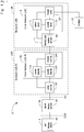
- Fig. 2 illustrates the proposed system architecture in more detail.
- Fig. 2 illustrates the UE-R 3R configured for relaying of signalling (e.g. user-plane and/or control-plane data) between the user communication device 3 and an associated ReNB 5 over a Layer 2 link 28 and using the UE-R's 3R EPS bearer (and/or the like).
- signalling e.g. user-plane and/or control-plane data
- UE-R's 3R EPS bearer and/or the like.
- an appropriate external/internal bearer may also be provided to complement the EPS bearer towards the network 10 in which the ReNB 5 is located, however, such external/internal bearer has been omitted for clarity.
- the UE-R 3R is connected to (served by) the network infrastructure 10R, which comprises the base station 5R, the MME 11R, and the gateways 13R/14R.
- the other user communication device 3 is connected to the UE-R 3R via an appropriate D2D interface (e.g. using a ProSe radio bearer).
- the network infrastructure 10 serving the user communication device 3 comprises the ReNB 5, the MME 11, and the gateways 13/14.
- the user communication device 3 is not connected directly to a serving base station via an appropriate radio bearer. Instead, the user communication device 3 is connected to a so-called remote eNB 5 or ReNB 5 network entity, using a Layer 2 link 28.
- the Layer 2 link 28 is established through the UE-R 3R, the base station 5R serving the UE-R 3R, and the gateways 13R/14R.
- the Layer 2 link 28 established between the relayed user communication device 3 and the ReNB 5 can be regarded as being analogous to a regular radio link composed on the MAC and PHY layers between user equipment and a serving base station operating in accordance with the 3GPP TS 36.300 standard. Accordingly, the ReNB 5, using the Layer 2 link, is able to provide similar (or the same) functionality to the relayed user communication device 3, as a standard eNB to a non-relayed UE.
- relay-server functionality is provided in the UE-R 3R
- relay-client functionality is provided in the user communication device 3
- ReNB-server functionality is provided in the ReNB 5.
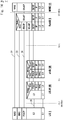
- Fig. 3 illustrates schematically the various layers and protocols of the entities shown in Fig. 1 , and the various associations between different entities (and corresponding layers thereof) that may communicate with each other using such layers and protocols.
- an end-to-end IP connection 20 e.g. an EPS bearer
- the relayed user communication device 3 and its associated gateway e.g. P-GW 14
- an external bearer 21 towards an endpoint in an external network (e.g. a node in the IP PDN 15).
- the end-to-end IP connection 20 between the relayed user communication device 3 and its associated gateway may be provided over an EPS bearer established by the MME11.
- This EPS bearer is supported by an E-RAB established between the relayed user communication device 3 and the S-GW 13 and an S5/S8 bearer established between the S-GW 13 and the P-GW 14. Further details of the IP connection 20 and its associated bearers are given with reference to Fig. 4 below.
- An end-to-end NAS connection 22 is provided between the relayed user communication device 3 and its associated MME 11, and an end-to-end RRC connection 23 is provided between the relayed user communication device 3 and its associated ReNB 5.
- the RRC/NAS signalling (and/or any IP signalling) is tunnelled using a Layer 2 link 28 between the user communication device 3 and the ReNB 5.
- the PDU transported over the end-to-end IP connection 20, or over the RRC end-to-end RRC connection 23 are transported using an optional PDCP protocol connection 24 established between the relayed user communication device 3 and ReNB 5, using the Layer 2 link 28 formed by the D2D link 29, the relay functionality in 3R, and the link 25.
- the Layer 2 link 28 is established using the respective relay-client 44, relay-server 45, and ReNB-server 65 functions provided at the relayed user communication device 3, the UE-R 3R, and the ReNB 5, respectively.
- the UE-R 3R also has its own IP connection 26 (e.g. an EPS bearer) to its own gateway (P-GW 14R), which is also complemented by a corresponding external bearer 27 towards other networks, in this example, to the network of the ReNB 5 (if different than the UE-R's 3R network).
- IP connection 26 e.g. an EPS bearer
- P-GW 14R gateway
- an appropriate internal bearer e.g. another EPS bearer
- the UE-R 3R also maintains a pair of associated RRC and NAS connections to its serving base station 5R and MME 11R, respectively.
- D2D bearer 29 (e.g. a ProSe bearer) established between the relayed mobile communication device 3 and the UE-R 3R (over Layer 2) that is coupled (relayed) to a link 25 between the UE-R 3R and the ReNB 5 (using e.g. the UE-R's 3R IP connection 26 and external bearer 27).
- a ProSe bearer e.g. a ProSe bearer
- the relayed user communication device 3 running on the relayed user communication device 3 and a corresponding application in the IP PDN 15 by sending the data to the IP layer, from where it is (optionally) passed down to the PDCP layer (if present), and then to the layer(s) responsible for communications over the D2D bearer 29.
- the data received from higher layers is forwarded over the D2D bearer 29 to the UE-R 3R, then the data is relayed over the link 25 to the ReNB 5, where it is passed to the PDCP layer for processing (i.e. if PDCP is used).
- the PDCP layer for processing (i.e. if PDCP is used).
- the gateway(s) 13/14 serving the relayed user communication device 3 and from the P-GW 14 to the IP PDN 15, where it is delivered to the appropriate application (e.g. based on a destination IP address associated with the data).
- RRC/NAS signalling can be communicated using the same path as for application data between the relayed user communication device 3 and the PDCP layer of the ReNB 5, from where the signalling is passed to the RRC layer (in case of RRC signalling) or to the MME 11 (in case of NAS signalling) rather than being forwarded to the IP PDN 15.
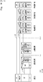
- Fig. 4 illustrates schematically a bearer architecture in which a Layer 2 link 28 is provided for communicating data between a user communication device 3 and the associated ReNB 5 when D2D relaying is in place.
- an end-to-end service can be provided between two communication endpoints (e.g. between a user communication device 3 and an application in the IP PDN 15) over an associated EPS bearer 20 (and/or the like).
- the EPS bearer 20 may be complemented by an external bearer when, as in this example, the other endpoint is located outside the core network 9 (in which P-GW 14 is located).
- Such an EPS bearer 20 is provided using an associated E-RAB bearer between the user communication device 3 and its S-GW 13, and using S5/S8 bearer between the S-GW 13 and the P-GW 14.
- the associated E-RAB bearer is realised by the Layer 2 link 28 and an S1 bearer provided between the ReNB 5 and the S-GW 13 (i.e. the gateway serving the relayed UE 3).
- the Layer 2 link 28 is composed of an appropriate L2 D2D (e.g. ProSe) bearer 29 established between the user communication device 3 and the UE-R 3R and an associated link 25 provided between the UE-R 3R and the ReNB 5.
- L2 D2D e.g. ProSe
- the Layer 2 link 28 may be regarded as a tunnel for transporting PDUs between the relayed user communication device 3 and the ReNB 5.
- the link 25 between the respective transport layers of the UE-R 3R and the ReNB 5 may be implemented e.g. using a suitable transport protocol, such as SCTP, TCP, UDP, RTP and/or the like.
- a suitable transport protocol such as SCTP, TCP, UDP, RTP and/or the like.
- Such suitable transport protocol may be provided over an IP layer established between the UE-R 3R and the S/P-GW 13R/14R through an IP link 26 (e.g. an EPS bearer), and between the P-GW 14R and the ReNB 5 through another IP link 27 (e.g. an external bearer).
- the transport protocols may be directly provided by the IP layer.
- the remaining bearers comprise bearers (e.g. regular/ default bearers) established for the UE-R 3R for the provision of communication between the UE-R 3R and other nodes. Accordingly, such (UE-R specific) bearers may be used generally for communications between the UE-R 3R and the ReNB 5 via the network entities serving the UE-R 3R.
- bearers e.g. regular/ default bearers
- an end-to-end service can be provided between the relaying user communication device 3R and the ReNB 5 over an associated (UE-R specific) EPS bearer 26 (and/or the like) and a complementary bearer (e.g. an external bearer 27 when the ReNB 5 is located outside the network 10R serving the UE-R 3R).
- an associated (UE-R specific) EPS bearer 26 and/or the like
- a complementary bearer e.g. an external bearer 27 when the ReNB 5 is located outside the network 10R serving the UE-R 3R.
- the UE-R's 3R EPS bearer 26 is provided using an associated E-RAB bearer between UE-R 3R and S-GW 13R and a complementary S5/S8 bearer between S-GW 13R and the P-GW 14R.
- the E-RAB bearer for the UE-R 3R is further provided over an associated Radio bearer and an S1 bearer.
- the Radio bearer extends between the UE-R 3R and its serving base station 5R, and it is complemented by the S1 bearer between the serving base station 5R and the S-GW 13R (i.e. the gateway serving the UE-Relay 3R).
- Any data received using the UE-R's 3R bearers and that is intended for the relayed user communication device 3 are passed to the relayed user communication device 3 using an associated D2D radio bearer (normally corresponding to an L1 bearer), from where it is passed on to higher layers (and vice versa).
- an associated D2D radio bearer normally corresponding to an L1 bearer
- Fig. 4 it is possible to provide an RRC connection between the ReNB 5 and the relayed user communication device 3 (and hence to treat the relayed UE 3 as being connected to the network) without requiring the UE-R 3R to implement base station (eNB) functionality.
- eNB base station
- an appropriate NAS connection can also be provided between the MME 11 and the relayed user communication device 3 to support mobility related signalling for the relayed user communication device 3.
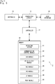
- Fig. 5 is a functional block diagram illustrating some of the functionality of a user communication device 3 (e.g. the relayed user communication device 3 shown in Fig. 1 ).
- the user communication device 3 has a transceiver circuit 31 that is operable to transmit signals to and to receive signals from a base station and/or other user communication devices via one or more antenna 33.
- the user communication device 3 has a controller 37 to control the operation of the user communication device 3.
- the controller 37 is associated with a memory 39 and is coupled to the transceiver circuit 31.
- the user communication device 3 will of course have all the usual functionality of a conventional user communication device (such as a user interface 35) and this may be provided by any one or any combination of hardware, software and firmware, as appropriate.
- Software may be pre-installed in the memory 39 and/or may be downloaded via the communication network or from a removable data storage device (RMD), for example.
- RMD removable data storage device
- the controller 37 is configured to control overall operation of the user communication device 3 by, in this example, program instructions or software instructions stored within the memory 39.
- these software instructions include, among other things, an operating system 41, a communication control module 42, a device-to-device (D2D) module 43, a relay-client module 44, a NAS module 46, an RRC module 47, an IP module 48, and a PDCP module 49.
- D2D device-to-device
- NAS module 46 e.g. base station, MME, P-GW, another UE, etc.
- the communication control module 42 handles (e.g. generates, sends and receives) control signals for controlling the connections between the user communication device 3 and other user communication devices, base stations, or the core network entities.
- the communication control module 42 also controls the separate flows of uplink/ downlink data and signalling that are to be transmitted to/from the other user communication devices, base stations, and the core network entities.
- the device-to-device module 43 is operable to assist the communication control module 42 in setting up a device-to-device communication path (e.g. ProSe based) to other compatible user equipment in the vicinity of the user communication device 3 (e.g. following an appropriate discovery procedure).
- the device-to-device module 43 may have both L1 and L2 functionality and communicates (e.g. user-plane or control-plane data) with corresponding device-to-device modules of other communication devices using appropriately formatted D2D (e.g. ProSe) PDUs.
- the relay-client module 44 communicates (using the services of the device-to-device module 43) with the relay-server module 45 of the UE-Relay 3R and the ReNB-server module 65 of the ReNB 5 serving the user communication device 3 in order to establish the Layer 2 link(s) 28 between the UE 3 and the ReNB 5.
- the relay-client module 44 may be considered as a control module for the initiation, establishment, and maintenance of communication between the various other modules (layers).
- the NAS module 46 handles (e.g. generates, sends and receives) Non-Access Stratum signalling messages in conformance with the relevant 3GPP (e.g. LTE) standards.
- the NAS module 46 communicates with, amongst others, the MME 11 serving the user communication device 3.
- the RRC module 47 handles (e.g. generates, sends and receives) Radio Resource Control signalling messages in conformance with the relevant 3GPP (e.g. LTE) standards.
- the RRC module 47 communicates with, amongst others, the ReNB 5 (and/or the UE-R 3R) serving the user communication device 3.
- the IP module 48 handles (e.g. generates, sends and receives) data packets conforming to the Internet Protocol standards (e.g. IPv4, IPv6, Mobile IP, etc.).
- the IP module 48 communicates with, amongst others, the P-GW 14 serving the user communication device 3, with the IP PDN 15 (via the P-GW 14), and/or corresponding IP modules 48 of other communication nodes.
- the IP module 48 may include a user-plane sub-module (for user data) and/or a control-plane sub-module (for control data), where appropriate.
- the IP module 48 may also include one or more sub-modules for realising an appropriate IP transport protocol such as TCP, SCTP, UDP, RTP and/or the like.
- the PDCP module 49 (which is optional) performs various services associated with the PDCP layer, in particular, services related to mobility and/or security. If present, the services performed by the PDCP module 49 include, amongst others: ciphering/ deciphering, header compression/decompression, in-sequence packet delivery, duplicate detection, and/or packet retransmission services. Although not shown in Fig. 5 , the PDCP module 49 may include a user-plane sub-module (for user-plane PDCP functions) and/or a control-plane sub-module (for control-plane PDCP functions), where appropriate.
- User communication device (configured as a UE-R)
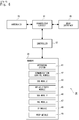
- Fig. 6 is a functional block diagram illustrating some of the functionality of a user communication device (e.g. the UE-R 3R shown in Fig. 1 ) when it is configured for relaying data for other user equipment.
- a user communication device e.g. the UE-R 3R shown in Fig. 1
- like-numbered modules carry out the same functionality, where appropriate.
- the relaying user communication device 3R has a transceiver circuit 31 that is operable to transmit signals to and to receive signals from a base station 5R and/ or other user communication devices 3 via one or more antenna 33.
- the relaying user communication device 3R has a controller 37 to control the operation of the relaying user communication device 3R.
- the controller 37 is associated with a memory 39 and is coupled to the transceiver circuit 31.
- the relaying user communication device 3R will of course have all the usual functionality of a conventional user communication device 3 (such as a user interface 35) and this may be provided by any one or any combination of hardware, software and firmware, as appropriate.
- Software may be pre-installed in the memory 39 and/or may be downloaded via the communication network or from a removable data storage device (RMD), for example.
- RMD removable data storage device
- the controller 37 is configured to control overall operation of the relaying user communication device 3R by, in this example, program instructions or software instructions stored within the memory 39.
- these software instructions include, among other things, an operating system 41 a communication control module 42, a device-to-device (D2D) module 43, a relay-server module 45, a NAS module 46, an RRC module 47, an IP module 48, and a PDCP module 49.
- the relaying user communication device 3R may include additional modules, e.g. the relay-client module 44, if appropriate.
- the communication control module 42 handles (e.g. generates, sends and receives) control signals for controlling the connections between the relaying user communication device 3R and other user communication devices 3, the base station 5, or the core network entities.
- the communication control module 42 also controls the separate flows of uplink/downlink data and signalling that are to be transmitted from/to the other user communication devices 3, to/from the base station 5, and the core network entities.
- the device-to-device module 43 is operable to assist the communication control module 42 in setting up a device-to-device communication path (e.g. a ProSe based) to other compatible user equipment in the vicinity of the user communication device 3R (e.g. following an appropriate discovery procedure).
- the device-to-device module 43 may have both L1 and L2 functionality and communicates (e.g. user-plane data and control-plane data) with corresponding device-to-device modules of other communication devices using appropriately formatted D2D (e.g. ProSe) PDUs.
- the relay-server module 45 communicates (using the services of the device-to-device module 43) with the relay-client module 44 of connected (relayed) user communication devices and the ReNB-server module(s) 65 of the ReNB(s) 5 serving such connected user communication devices.
- the relay-server module 45 facilitates communication between the relay-client module 44 and the ReNB-server module 65 by controlling the relaying between a D2D bearer (established with a particular connected user communication device) and the associated link(s) 25 established with the ReNB 5 serving that particular connected user communication device.
- the NAS module 46, the RRC module 47, the IP module 48, and the PDCP module 49 of the UE-R 3R essentially correspond to the respective like-numbered modules described with reference to Fig. 5 , thus their description is not repeated here.
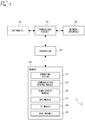
- Fig. 7 is a functional block diagram illustrating some of the functionality of a remote base station 5 forming part of the system 1 shown in Fig. 1 .
- the remote base station 5 has a transceiver circuit 51 that is operable to transmit signals to and to receive signals from user communication devices 3 via one or more antenna 53 (optional) and/or a network interface 55 and to transmit signals to and to receive signals from network nodes via the network interface 55.
- the remote base station 5 has a controller 57 to control the operation of the remote base station 5.
- the controller 57 is associated with a memory 59 and is coupled to the transceiver circuit 51.
- the controller 57 is configured to control overall operation of the remote base station 5 by, in this example, program instructions or software instructions stored within the memory 59.
- Software may be pre-installed in the memory 59 and/or may be downloaded via the communication network or from a removable data storage device (RMD), for example.
- RMD removable data storage device
- these software instructions include, among other things, an operating system 61, a communication control module 63, a ReNB-server module 65, an RRC module 67, an IP module 68, and a PDCP module 69.
- the communication control module 63 handles (e.g. generates, sends and receives) control signals for controlling the connections between the remote base station 5 and the communication devices 3, the base station 5R, or the core network entities.
- the communication control module 63 also controls the separate flows of uplink/downlink data and signalling that are to be transmitted from/to the user communication devices 3, and the other network entities.
- the ReNB-server module 65 controls communications (together with the relay-server module 45 of the UE-R 3R and the relay-client module 44 of the relayed user communication device 3) over the Layer 2 link(s) 28 between the relayed user communication device 3 and the ReNB 5.
- the RRC module 67 handles (e.g. generates, sends and receives) Radio Resource Control signalling messages.
- the RRC module 67 communicates with, amongst others, the corresponding RRC module 47 of relayed user communication devices 3 served by the ReNB 5.
- the RRC module 67 is operable to extract, from messages received over the Layer 2 link, and process RRC messages. If the extracted RRC message includes an NAS message, the RRC module 47 is operable to forward the extracted NAS message to the MME 11 (e.g. using an S1-AP interface provided between the ReNB 5 and the MME 11).
- the RRC module 67 receives (NAS) messages from the MME 11 (through the S1-AP) and forwards them to the UE-R 3R to be relayed to and processed by the UE 3 (e.g. over the underlying transport layer and, optionally, via the PDCP module 69, if PDCP is used).
- NAS NAS
- the UE-R 3R receives (NAS) messages from the MME 11 (through the S1-AP) and forwards them to the UE-R 3R to be relayed to and processed by the UE 3 (e.g. over the underlying transport layer and, optionally, via the PDCP module 69, if PDCP is used).
- the IP module 68 handles (e.g. generates, sends and receives) data packets conforming to the Internet Protocol standards (e.g. IPv4, IPv6, Mobile IP, etc.).
- the IP module 68 communicates with, amongst others, user communication devices 3, the P-GW 14 serving a particular user communication device 3, and/or with the IP PDN 15 (via the P-GW 14).
- the IP module 68 may also be responsible for communicating with the P-GW 14R and/or other entities from the UE-R's 3R network 10R (through the P-GW 14R if necessary).
- the IP module 68 may include a user-plane sub-module (for user data) and/or a control-plane sub-module (for control data), where appropriate.
- the IP module 68 may also include one or more sub-modules for realising an appropriate IP transport protocol such as TCP, SCTP, UDP, RTP and/or the like.
- the (optional) PDCP module 69 performs various services associated with the PDCP layer, in particular, services related to mobility and/or security of user communication devices 3.
- the services performed by the PDCP module 69 include, amongst others: ciphering/deciphering, header compression and decompression, in-sequence packet delivery, duplicate detection, and/or packet retransmission services.
- the PDCP module 69 may include a user-plane sub-module (for user-plane PDCP functions) and/or a control-plane sub-module (for control plane PDCP functions), where appropriate.
- the PDCP module 69 (or an appropriate transport layer function, e.g. if PDCP is not used) can receive messages over the Layer 2 link 28 (e.g. from the PDCP module 49 / transport layer function of the relayed user communication device 3), and forward the received messages, in dependence on the contents of the received messages, to the RRC module 67 (in case of control-plane messages), and/or to the appropriate P-GW 14 (in case of user-plane messages).
- the PDCP module 69 is operable to receive user-plane data from the P-GW 14 (e.g.
- the PDCP module 69 is operable to forward the received message/data using the appropriate Layer 2 link 28 established with the corresponding relayed user communication device 3 (e.g. to the PDCP module 49 / transport layer function thereof).
- the user communication devices 3 and 3R, and the ReNB 5 are described for ease of understanding as having a number of discrete modules (such as the communications control modules, the relay-server/relay-client modules, and the NAS/RRC/IP/PDCP modules). Whilst these modules may be provided in this way for certain applications, for example where an existing system has been modified to implement the invention, in other applications, for example in systems designed with the inventive features in mind from the outset, these modules may be built into the overall operating system or code and so these modules may not be discernible as discrete entities. These modules may also be implemented in software, hardware, firmware or a mix of these.
- Fig. 8 is a timing diagram illustrating an exemplary way in which establishment of an RRC connection for a relayed user communication device 3 may be realised in the system shown in Fig. 1 .
- the user communication device 3 is configured (e.g. using its D2D module 43) for being relayed (e.g. because it is determined that the user communication device 3 is currently out of network coverage).
- the other user communication device 3R is set up to operate as a UE-Relay (although there may not be any user equipment connected to it yet) at least whilst the UE-R 3R is within the coverage of the network (base station 5R).
- step S101 the user communication devices 3 and 3R perform a relay discovery procedure (using their respective D2D modules 43).
- the procedure at step S101 is optional and can be initiated by either user communication device by sending an appropriate D2D beacon, and the relay discovery procedure may comprise exchanging one or more signalling messages between the user communication devices 3 and 3R (and possibly involving the base station 5R and/or a core network entity, e.g. the MME 11R).
- the user communication device 3 After the discovery procedure has been completed, and the user communication device 3 has identified the UE-R 3R, the user communication device 3 (using its relay-client module 44) and the UE-R 3R (using its relay-server module 45) identify/select a suitable ReNB 5 for the user communication device 3, and proceed to establish a Layer 2 link between the relayed user communication device 3 and the ReNB 5.
- step S103 the user communication device 3 (using its relay-client module 44 and D2D module 43) initiates registration with the UE-R 3R (i.e. with the relay-server 45 module thereof) for using UE-Relay services. Specifically, the user communication device 3 generates (using its D2D module 43) and sends an appropriately formatted signalling message (which may comprise e.g. a ProSe PDU) to the UE-R 3R.
- an appropriately formatted signalling message which may comprise e.g. a ProSe PDU
- the user communication device 3 includes in this message:
- the contents of the message are passed to the relay-server module 45 for processing.
- step S104 the UE-R 3R (using its relay-server module 45), possibly with support by the network, identifies the ReNB 5 designated/selected for serving the relayed user communication device 3 (e.g. based on the Relay registration request and/or the GUTI, if provided). Specifically, in this example, the UE-R 3R obtains an Access Point Name (APN) associated with the ReNB 5.
- APN Access Point Name
- step S107 the UE-R 3R (using its relay-server module 45) initiates establishment of an EPS bearer for the APN associated with the ReNB 5. Effectively, this EPS bearer serves as a default EPS bearer for the relayed user communication device 3.
- the UE-R 3R (the relay-server module 45) also initiates the establishment of an IP connection between the UE-R 3R and the ReNB 5 for the purpose of relaying data for the user communication device 3.
- step S109 the UE-R 3R also performs any procedures appropriate for the newly established IP connection, e.g. identification of the IP address associated with the ReNB 5 and/or security procedures.
- the IP connection is established, in this example, between an IP address associated with the ReNB's 5 APN on one end, and an IP address associated with the UE-R 3R (e.g. its EPS bearer) on the other end.
- step S110 the user communication device 3 and the UE-R 3R (using their respective D2D modules 43) initiate the establishment of a D2D bearer 29 between the relayed user communication device 3 and the UE-R 3R.
- the UE-R 3R is configured for relaying traffic between the user communication device 3 (i.e. the D2D interface) and the ReNB 5 (i.e. the UE-R's 3R IP connection 26 towards the ReNB 5).
- the UE-R 3R creates a mapping between the relayed user communication device 3 and the ReNB 5, e.g. by keeping an appropriate association between the Layer 2 identifier for the relayed user communication device 3 and the corresponding transport connection 25 established towards the ReNB 5.
- the UE-R 3R In step S113, the UE-R 3R generates (using its D2D module 43) and sends an appropriately formatted signalling message (which may comprise e.g. a ProSe PDU), and includes in this message a confirmation that the relay registration (requested in step S103) has been successfully completed.
- the UE-R 3R also includes in this message information identifying the type of message (so that it can be passed to the relay-client module 44 upon receipt), and information identifying the relayed user communication device 3 and the UE-R 3R (e.g. their associated Layer 2 identifiers), i.e. the recipient and the sender, respectively.
- a Layer 2 link 28 (and hence connectivity) is now established between the relayed user communication device 3 and the serving ReNB 5.
- multiple Layer 2 links 28 can be established between the relayed user communication device 3 and the ReNB 5 e.g. by repeating steps S103 to S115.
- multiple Layer 2 links 28 may also be established at once, e.g. by including multiple requests in the ProSe PDU sent in step S103 and processing/ confirming the multiple requests substantially together (in steps S104 to S113).
- separate Layer 2 links 28 may be used for relaying control-plane and user-plane PDUs, respectively, e.g. in accordance with any of Figs. 10 to 16 .
- each Layer 2 link 28 may beneficially have its own associated Quality of Service (QoS), e.g. adapted to the transported PDUs over that particular Layer 2 link 28.
- QoS Quality of Service
- step S117 using the appropriate Layer 2 link 28 established between them, the relayed user communication device 3 and the ReNB 5 proceed to setup an appropriate PDCP connection 24 with each other (e.g. by configuring their respective PDCP modules 49 and 69, as required).
- the PDCP connection 24 allows the two endpoints (i.e. the relayed user communication device 3 and the ReNB 5) to communicate securely and effectively (e.g. by applying appropriate PDCP services, such as ciphering, header compression, in-sequence packet delivery, duplicate detection, packet retransmission, and/or the like).
- the relayed user communication device 3 and the ReNB 5 proceed to establishing an RRC connection 23 using the PDCP connection 24 and the Layer 2 link 28 established between them.
- the relayed user communication device 3 initiates RRC connection 23 establishment by generating (using its D2D module 43) and sending, at step S118, an appropriately formatted signalling message (which may comprise e.g. a ProSe PDU) to the UE-R 3R.
- the D2D module 43 also includes in this message an appropriately formatted RRC Connection Request message (provided by the RRC module 47).
- the RRC message is included in an appropriately formatted PDU (comprised within the ProSe PDU) addressed to the ReNB 5.
- the message also includes information identifying the sender and the recipient (e.g. their respective Layer 2 identifiers) and information identifying the type of message (i.e. 'Relay PDU Protocol' message to be processed by the relay-server module 45 of the UE-R 3R).
- the UE-R 3R (using its D2D module 43) receives ProSe message over the D2D bearer 29 and (using its relay-server module 45 and the 'Relay PDU protocol' message) forwards, in step S119, the PDU comprising the PDCP message comprising the RRC message to the ReNB 5 (that corresponds to the sender of the preceding message based on the earlier registration).
- the forwarded PDU is received by the PDCP module 69 (realised in some alternatives over the IP module 68) of the ReNB 5 and passed on to the RRC module 67 for processing.
- the ReNB 5 In step S121, the ReNB 5 generates and sends an appropriately formatted signalling message to the UE-R 3R (e.g. using a PDU comprising a PDCP PDU), and includes in the message a response to the RRC Connection Request received in the preceding step.
- the response comprises an RRC message provided by the RRC module 67, e.g. an 'RRC Connection Setup' message, for the relayed user communication device 3.
- the UE-R 3R In response to this message, the UE-R 3R generates (using its D2D module 43) and sends, in step S122, a signalling message including a ProSe PDU.
- the UE-R 3R includes in this PDU the ReNB's 5 RRC Connection Setup message received in the preceding step.
- the UE-R 3R includes in this PDU information identifying the sender and the receiver (e.g. by their appropriate Layer 2 identifiers) and the type of message (in this case, Relay PDU protocol communication) so that the contents of this message are passed to the relay-client module 44 responsible for handling that type of messages.
- the relayed user communication device 3 configures its RRC module 47 in accordance with the received RRC Connection Setup message, and generates (using its D2D module 43) and sends, at step S124, an appropriately formatted signalling message (which may comprise e.g. a ProSe PDU) to the UE-R 3R.
- the D2D module 43 also includes in this message an appropriately formatted confirmation message, e.g. an 'RRC Connection Setup Complete' message (provided by the RRC module 47).
- the signalling message (ProSe PDU) may comprise a message (PDU) obtained by the D2D module 43 from a higher layer and/or a message (PDU) generated by the D2D module 43 itself.
- the D2D module 43 may be configured to adapt/modify the message (PDU) obtained from the higher layer, where appropriate, before forwarding the higher-layer message (PDU).
- a higher layer such as from the NAS layer (NAS module 46), the RRC layer (RRC module 47), the IP layer (IP module 48), and/or the PDCP layer (PDCP module 49).
- the RRC confirmation message (obtained from the RRC module 47) is included in an appropriately formatted PDU (comprised within the ProSe PDU) addressed to the ReNB 5.
- the message also includes information identifying the sender and the recipient (e.g. their respective Layer 2 identifiers) and information identifying the type of message (i.e. 'Relay PDU Protocol' message to be processed by the relay-server module 45 of the UE-R 3R).
- the UE-R 3R (using its D2D module 43) receives the ProSe message over the D2D bearer 29 and (using its relay-server module 45) forwards, in step S125, the PDU comprising the RRC confirmation message to the ReNB 5 (that corresponds to the sender of the preceding message based on the earlier registration).
- the forwarded PDU is received by the PDCP module 69 of the ReNB 5 and passed on to the RRC module 67.
- an RRC connection 23 has been successfully established (using the Layer 2 link) between the relayed user communication device 3 and the ReNB 5.
- This RRC connection 23 allows the exchange of radio level information, and can support communication in accordance with the RRC protocol as described in 3GPP TS 36.300 and TS.36.331. Accordingly, when the RRC module 47 (of the relayed user communication device 3) is in the so-called 'RRC_connected_mode', the ReNB 5 is able to provide similar (or the same) Access-Stratum (AS) services to the relayed user communication device 3 as provided by a conventional eNB to non-relayed user equipment.
- AS Access-Stratum
- RRC_connected_mode various RRC services may be realised in the 'RRC_connected_mode', including security and mobility functions in particular.
- RRC security functions are made possible by the establishment of a data bearer and an associated PDCP connection 24 between the relayed user communication device 3 and the ReNB 5 (transparently, via the UE-R 3R).
- RRC mobility functions may include, for example, UE measurement functions (such as signal quality and/or interference measurements), and the transfer of NAS messages by the ReNB 5 (e.g. to/from the MME 11).
- the NAS protocol of the user communication device 3 is not impacted (or it can be reused with minimum impact) because the NAS protocol is realised according to the existing standards. Therefore, the ReNB 5 assures the transfer of any NAS message to the MME 11 with minimum impact on the S1-AP interface and RRC transfer functions.
- the NAS protocol and its procedures are described in the 3GPP TS 23.401 standards specification, including procedures performed in the so-called 'ECM-CONNECTED' mode of operation, i.e. when a particular item of user equipment has an EPS Connection Management (ECM) connection with its serving MME for communicating NAS messages.
- ECM EPS Connection Management
- the relayed user communication device 3 is able to perform, for example, an attach procedure, a tracking area update (TAU) procedure with its MME 11, and/or a default bearer establishment procedure (which is shown in Fig. 8 ).
- TAU tracking area update
- a default bearer establishment procedure which is shown in Fig. 8 .
- the MME 11 might consider the relayed user communication device 3 to be within a specific tracking area (i.e. a different tracking area than the base station 5 / UE-R 3R belong to) as the relayed user communication device 3 is not connected to its core network 9 directly, but through the UE-R 3R.
- a dedicated EPS bearer can be established between the UE-R 3R and the P-GW 14R (and a corresponding IP connection established between the UE-R 3R and the ReNB 5), which makes it possible for the relayed user communication device 3 to operate in the 'ECM-CONNECTED' mode and to communicate NAS messages with the MME 11 (over the Layer 2 link provided via the UE-R 3R and the ReNB 5).
- Fig. 9 is a timing diagram illustrating an exemplary way in which establishment of a dedicated EPS bearer for a relayed user communication device 3 may be realised in the system shown in Fig. 1 .
- the establishment of the dedicated EPS bearer is for the purpose of communicating user-plane data between the relayed user communication device 3 and a communication node in the IP PDN 15.
- the procedure shown in Fig. 9 might be performed as part of (e.g. continuation of) the procedure described above with reference to Fig. 8 or it might be performed as a separate procedure.
- an external bearer 21 is provided between the IP PDN 15 and the P-GW 14 serving the relayed user communication device 3 (although it is noted that this step may be performed as part of a subsequent step, e.g. S220). It is also assumed that the relayed user communication device 3 has established a NAS connection 22 with the MME 11, supported by the Layer 2 link 28 with its serving ReNB 5, having followed the procedures described with reference to Fig. 8 . Accordingly, the relayed user communication device 3 is able to exchange control-plane (e.g. RRC/NAS) signalling messages with the ReNB 5 and the MME 11 (via the ReNB 5).
- control-plane e.g. RRC/NAS
- step S202 the relayed user communication device 3 requests the MME 11 to allocate a dedicated bearer, e.g. using the control-plane connection (over the Layer 2 link 28) established with the ReNB 5. It does so by generating (using its NAS module 46) and sending (using its control-plane connection) an appropriately formatted NAS service request (e.g. a 'Dedicated bearer request' message) to the MME 11.
- a dedicated bearer e.g. using the control-plane connection (over the Layer 2 link 28) established with the ReNB 5. It does so by generating (using its NAS module 46) and sending (using its control-plane connection) an appropriately formatted NAS service request (e.g. a 'Dedicated bearer request' message) to the MME 11.
- the MME 11 proceeds to set up the gateways 13/14 for handling traffic associated with the requested dedicated bearer and sends an appropriate confirmation to the relayed user communication device 3, when the configuration of the gateways 13/14 has been completed.
- the relayed user communication device 3 proceeds to initiating the creation of a dedicated Layer 2 link (as opposed to the 'default' Layer 2 link established in step S115 of Fig. 8 ) corresponding to the dedicated EPS bearer requested in step S202.
- the relayed user communication device 3 generates (using its D2D module 43) and sends, in step S205, an appropriately formatted message, in a ProSe PDU, to the UE-R 3R.
- the relayed user communication device 3 includes in this message an indication of the type of bearer requested, e.g. a request for a dedicated bearer to the ReNB 5 for relaying user-plane data via the UE-R 3R.
- the PDU includes information identifying the relayed user communication device 3 (e.g. an associated Layer 2 identifier), information identifying the UE-R 3R (e.g. an associated Layer 2 identifier), and a request for establishment of the dedicated bearer.
- the PDU sent at S205 is processed by the relay-server module 45 of the UE-R 3R, which then proceeds to step S207. Whilst step S205 is similar to S103 (both initiates the establishment of an IP connection with the ReNB 5), at this phase, APN identification for the ReNB 5 (as described above with reference to step S104) may not be necessary, since the UE-R 3R might have previously registered the relayed user communication device 3, thus it might have already performed step S104.
- step S207 the UE-R 3R (e.g. using its relay-server module 45) initiates establishment of the requested (dedicated) EPS bearer to an APN associated with the ReNB 5 (e.g. in addition to any existing or 'default' EPS bearer it already has with the ReNB 5).
- step S209 the UE-R 3R (e.g. using its relay-server module 45) also initiates the establishment of an IP connection 26 between the UE-R 3R and the ReNB 5 for the purpose of relaying data (in this case, user-plane data) for the user communication device 3.
- IP address identification for the ReNB 5 may not be necessary, since the UE-R 3R might have already registered the relayed user communication device 3, thus it might have already performed step S109.
- step S210 the relayed user communication device 3 and the UE-R 3R (using their respective D2D modules 43) initiate the establishment of a D2D bearer 29 between the relayed user communication device 3 and the UE-R 3R.
- the user communication device 3 and the UE-R 3R may perform a reconfiguration of an existing D2D bearer 29 between them (e.g. the reconfiguration of a 'default' D2D bearer established in step S110), instead of establishing a new D2D bearer 29.
- the UE-R 3R is configured for relaying traffic between the user communication device 3 and the ReNB 5 (i.e. traffic communicated over the requested dedicated bearer).
- the UE-R 3R generates (using its D2D module 43) and sends an appropriately formatted message, e.g. in a ProSe PDU, and includes in this message a confirmation that the requested dedicated bearer has been successfully set up.
- the UE-R 3R also includes in this message information identifying the relayed user communication device 3 and the UE-R 3R (e.g. their associated Layer 2 identifiers), and the type of message (e.g. 'Relay control protocol' message) so that it can be passed to the appropriate relay-client module 44.
- the confirmation is processed by the client-server module 44 of the relayed user communication device 3, which determines, at step S215, that a Layer 2 link 28 is now established between the relayed user communication device 3 and the serving ReNB 5 for the requested dedicated bearer.
- step S217 using the appropriate Layer 2 link 28 established between them, the relayed user communication device 3 and the ReNB 5 proceed to setup an appropriate PDCP connection with each other (e.g. by an appropriate configuration of their respective PDCP modules 49 and 69).
- the relayed user communication device 3 receives an appropriately formatted message, e.g. from the MME 11, informing the relayed user communication device 3 that the activation of the requested dedicated bearer is complete.
- the MME 11 may send an 'Activate dedicated bearer ctx accept' NAS message to the relayed user communication device 3 (i.e. the NAS module 46 thereof) via the ReNB 5 and over the Layer 2 link 28 provided between the ReNB 5 and the relayed user communication device 3.
- the MME's 11 NAS message is sent, using an appropriately formatted S1-AP message, to the ReNB's 5 RRC module 67.
- the ReNB 5 (using its RRC module 67) transfers the message to the PDCP module 69 and sends the message towards the relayed user communication device 3 (the PDCP module 49 thereof) using an appropriate Layer 2 link 28 protocol.
- a user-plane connection is now established between the relayed user communication device 3 and the IP PDN 15 (e.g. an application in the IP PDN 15).
- the relayed user communication device 3 is able to communicate user-plane data with a communication endpoint in the IP PDN 15.
- the UE-R can be connected to any type of network infrastructure (including UMTS, Wi-Fi, and/or the like).
- the relayed UE (using an associated relay-client module 44) and the UE-R (using an associated relay-server module 45) determine the IP address for communicating with the ReNB (e.g. based on an APN name) and establish a Layer 2 link (or links) between the relayed UE and the ReNB.
- Figs. 10 to 13 illustrate various exemplary protocol stacks (for the relayed UE, the UE-R, the ReNB, and the other network nodes) that may be used to put the above described procedures into use.
- Fig. 10 illustrates schematically the exemplary control-plane protocol stacks of the elements shown in in Fig. 1 involved in the relaying of control-plane signalling between the relayed user communication device 3 and its serving network 10.
- relaying of control-plane e.g. NAS/RRC
- the Transport layer between the ReNB 5 and the UE-R 3R e.g. over link 25 provided between the respective IP addresses associated with the UE-R 3R and the ReNB 5
- the relaying layers between the UE-R 3R and the UE 3 are realised by using appropriate device-to-device Layer 2 and Layer 1 communication technologies (denoted 'ProSe L2' and 'ProSe L1' in Fig. 10 ).
- the Layer 2 and Layer 1 communication technologies are based on standard LTE radio technologies.
- the relayed user communication device 3 is therefore able to communicate RRC signalling (to/from the ReNB 5) and/or NAS signalling (to/from the MME 11) and it can thus be perceived as connected to the network (e.g. upon completion of appropriate RRC/NAS procedures).
- the layer 2 (end-to-end) user-plane may be realised by: i) providing a ProSe D2D link 29 between the relayed user communication device 3 and the UE-R 3R; ii) relaying within the UE-R 3R at the Transport layer; and iii) transporting user-plane traffic in a link 25 between the UE-R 3R and the ReNB 5. This is further illustrated in Fig. 11 .
- Fig. 11 illustrates schematically the exemplary user-plane protocol stacks of the elements shown in Fig. 1 involved in the relaying of user-plane data between the relayed user communication device 3 and its serving network 10.
- Fig. 11 also shows the gateways 13/14 serving the relayed user communication device 3.
- user-plane e.g. IP
- IP device-to-device L2 and L1 communication technologies between the UE-R 3R and the relayed UE 3.
- the relayed user communication device 3 communicates IP signalling (and/or the like), such signalling is relayed at the Transport layer of the UE-R 3R and communicated via the P-GW 14 to/from an endpoint beyond the P-GW 14, e.g. an application in an external network / IP PDN (not shown in Fig. 11 ).
- Fig. 12 illustrates schematically exemplary control-plane protocol stacks of the elements shown in Fig. 1 when relaying (of control-plane signalling between the relayed user communication device 3 and its serving network 10) is performed at PDCP level.
- the Transport and IP layer functions are provided by the relayed user communication device 3 rather than the UE-R 3R (from where they have been omitted for clarity).
- (end-to-end) control-plane can be realised by: i) providing an appropriate D2D (e.g. ProSe) link 29 between the relayed user communication device 3 and the UE-R 3R; ii) relaying within UE-R 3R below the IP/Transport layers (since such layers are handled by the UE 3), e.g. at the PDCP layer; and iii) conveying IP packets using an appropriate transport connection 25 between the relayed user communication device 3 and the ReNB 5 (through respective GTP-U connections (and/or the like) between the base station 5 and the S-GW 13R, and between the S-GW 13R and the P-GW 14R).
- D2D e.g. ProSe
- Fig. 13 illustrates schematically exemplary user-plane protocol stacks of the elements shown in in Fig. 1 when relaying (of user-plane data between the relayed user communication device 3 and its serving network 10) is performed at PDCP level.
- the base station 5R serving the UE-R 3R
- the ReNB 5 serving the relayed UE 3
- the S-GW 13R is optional, i.e. the base station 5R and the ReNB 5 may be connected directly.
- the S-GW function may be integrated into the base station 5R (and/or the ReNB 5).
- there is no P-GW 14R and hence no relaying at the IP Level in a P-GW 14R - the end-to-to end connection comprises an IP connection directly between the relayed user communication device 3 and the P-GW 14.
- Figs. 14 and 15 illustrate schematically exemplary control-plane protocol stacks of the elements shown in Fig. 1 when relaying (of the relayed user communication device's 3 control-plane signalling) is performed using the X2 protocol.
- the X2-U (user-plane of X2) protocol is used between the base station 5R and the ReNB 5 to carry control-plane signalling for the relayed user communication device 3.
- the X2-C (control-plane of X2) protocol is used between the base station 5R and the ReNB 5 to carry control-plane signalling for the relayed user communication device 3.
- Fig. 16 illustrates schematically exemplary user-plane protocol stacks of the elements shown in Fig. 1 when relaying (of the relayed user communication device's 3 user-plane data) is performed using the X2 protocol.
- the X2-U protocol is used between the base station 5R and the ReNB 5 to carry user-plane data for the relayed user communication device 3.
- networks 10 and 10R may belong to (operated by) different network operators or the same network operator.
- the base station 5R and ReNB 5 may belong to (be operated by) different network operators or the same network operator, and the relayed UE 3 and UE-R 3R may have different network operators or the same network operator.
- the IP PDN is shown to be connected to the relayed UE's network 10. However, it will be appreciated that the IP PDN may also be connected to the UE-Relay's network 10R (e.g. to P-GW 14R) as well.
- the UE-Relay's network 10R e.g. to P-GW 14R
- two user communication devices 3 and 3R and two base stations 5 and 5R are shown in Fig. 1 for illustration purposes, additional user equipment and/or base stations may be present in a deployed system. It will also be appreciated that, although shown as separate networks in Fig. 1 , the two user communication devices 3 and 3R may be served by the same network (although in this case it will be appreciated that each user communication device 3 and 3R may be served by different MMEs and/or gateways of the same network). Further, it will be appreciated that, whilst shown as separate entities, the functionalities of the S-GW and the P-GW could be implemented in a single gateway element.
- the ReNB 5 is described to form part of a network associated with the relayed user communication device. It will be appreciated that the functionalities of the ReNB may be provided by any suitable core network entity and/or a RAN entity (e.g. a base station, a relay node, and/or a standalone ReNB node).
- a core network entity e.g. a base station, a relay node, and/or a standalone ReNB node.
- the additional ReNB 5 functionality may be implemented as part of a conventional eNB, with appropriate ReNB enhancements, that can therefore deal with relayed UEs that can be located somewhere else in the network (in this case the ReNB can also have same (or similar) functionalities as a conventional eNB (for example it may provide its own cell(s) and serve its own mobile devices directly (without relaying))) in addition to the functionalities for controlling and communicating with relayed UEs.
- ReNB may be implemented by a different network entity, for example, an entity that provides support for ProSe functionality from the network point of view.
- ReNB functionalities may be provided by the MME and/or any other suitable core network (and/or RAN) entity.
- a plurality of relayed UEs may share a common Layer 2 link ID, and may be connected and controlled using the common Layer 2 Link ID. This is likely to have benefits in terms of efficiency for situations such as Group Call Communications (application of GCSE and ProSe, when, for example, users are in relatively close proximity).
- an RRC connection could be provided over a PDCP connection between the UE-R and the eNB (serving the UE-R).
- RRC messages from a relayed user communication device will be encapsulated in the RRC messages of a UE-R when transferred to the eNB.
- the UE is described as sending the message that initiates provision of the end-to-end communication link between the UE and the ReNB, the link could be initiated by the UE-R sending a message to the UE.
- relayed (D2D) communication paths are described to use an LTE technology (i.e. the same communication technology that is used between the network and the relaying user communication device).
- LTE Long Term Evolution
- a D2D interface between the relayed UE and the UE-R may be realised using any communication technology, for example, WLAN, Wi-Fi, FlashLinQ, WiMAX, Bluetooth, BLE, ZigBee, etc. (irrespective of the communication technology used between the base station and the relaying user communication device).
- a Layer 2 communication link is provided between the relayed user communication device and the ReNB.
- the term 'Layer 2 link' in this case refers to the communication link from the point of view of the relayed user communication device, which may not correspond to Layer 2 from the network point of view. It will be appreciated that the network side of the 'Layer 2 link' may be connected to a different layer than the UE side, since "normal" network Layer 2 may correspond the same layer or it may correspond to a different layer (such as a layer below Layer 2).
- the relayed UE may also implement an IP layer as well, which may be associated with an optional transport layer.
- the transport layer may comprise e.g. a TCP layer, an UDP layer, an SCTP layer, and/or the like.
- the base station may comprise a Low Power Node (LPN), such as a home base station, a femto base station, and/or the like. It will also be appreciated that either one of (or both) the relaying and the relayed user communication devices may comprise a Low Power Node.
- LPN Low Power Node
- the UE-R and the ReNB may multiplex (e.g. using an appropriate multiplexing layer) multiple Layer 2 links they have with each other.
- the UE-R may multiplex multiple Layer 2 links (established for the same relayed UE or established for different relayed UEs) over a single IP connection with the ReNB.
- the relay-server module 45 of the UE-R 3R is described as initiating IP connection establishment. It will be appreciated, however, that the UE-R 3R may communicate the relayed UE's registration request (e.g. by forwarding the associated ProSe PDU) to the ReNB-server module 65 of the ReNB 5 and the ReNB 5 may initiate IP connection establishment based on that request (and/or carry out registration of the relayed UE 3).
- the messages transmitted in steps S119, S121, and S125 may also comprise appropriately formatted ProSe PDUs (i.e. the messages at steps S118, S122, and S124 may be relayed by the UE-R 3R).
- the relayed user communication device, the UE-R, and the ReNB are described to include the relay-client module, the relay-server module, and the ReNB-server module, respectively, which are configured to manage the control plane aspects of the establishment of a layer 2 link between the relayed user communication device and the ReNB.
- the relay-client module may have different names in different implementations.
- the functionality of the "relay-server” module and/or the "relay-client” module are not limited to server and/or client functionality only but are intended to cover both functionalities, where appropriate.
- the function of the "relay-server” module might be regarded as a client from the point of view of the ReNB-server module (and/or the relay-client module).
- the "relay-server” module might also be regarded as a relay (rather than a client and/or a server) since the relay-server module might be configured to simply relay messages between the relayed user communication device and the ReNB.
- a "relay-server” module may be dedicated to support a specific combination of communication endpoints (e.g. a specific ReNB and a specific relayed user communication device pair), in which case the functionality of the "relay-server” module may be limited to relaying functionality between the specific endpoints.
- the "relay-server” may not need to register the specific relayed user communication device and/or look up the APN corresponding to the specific ReNB that the dedicated "relay-server” module is configured to support.
- the relayed user communication device is described to communicate NAS signalling using its (ECM) connection with its serving MME.
- the relayed user communication device may request the MME to provide a service (e.g. a dedicated bearer) using NAS signalling.
- a service e.g. a dedicated bearer
- the relayed user communication device may be configured to exchange NAS signalling messages within user-plane PDUs, e.g. as described in steps S118 to S125 for RRC signalling messages.
- relay-client module may use any suitable communication protocol, e.g. a protocol derived from the RRC protocol specified in 3GPP TS 23.331.
- PDCP Packet Control Protocol
- the PDCP services may be limited to a subset of all PDCP functionalities.
- the UE-R and the relayed UE are served by different core networks.
- the serving core network for the UE-R may be the same as the relayed UE's core network.
- the user communication devices perform an optional discovery procedure in order to establish a D2D connection with each other. It will be appreciated that the user communication devices may realise such a discovery procedure by communicating any suitable messages to each other, e.g. by communicating system information broadcast (SIB) messages, master information block (MIB) messages, information exchange messages, messages forming part of a request/ reply-based mechanism, and/or the like.
- SIB system information broadcast
- MIB master information block
- information exchange messages messages forming part of a request/ reply-based mechanism, and/or the like.
- two user communication devices were allowed to establish a direct D2D connection with each other.
- such connections may be established between three or more user communication devices, such that the users of the user communication devices may be connected together in a conference call setup.
- a D2D bearer may be provided between three or more user communication devices (e.g. all relayed user communication devices can connect to their respective ReNB via the same UE-R).
- a D2D bearer is being set up between the relaying user communication device and the relayed user communication device(s) for relaying group service data. It will be appreciated that such a 'D2D bearer' may comprise at least one of: a D2D radio bearer; a D2D EPS bearer; a D2D service bearer; and/or the like.
- the UE-R is described as a standalone entity. However, it will be appreciated that the UE-R functionality described above may be implemented using multiple entities.
- the UE-R functionality (including an associated relay-server functionality) may be provided by a plurality of user communication devices connected in a hop-by-hop manner to a base station, using respective D2D/ProSe connections to provide each 'hop' between two neighbour user communication devices.
- the UE-R may be provided in the form of an apparatus, e.g. as a user communication device connected to a wireless router, laptop computer, and/or the like.
- the user equipment comprise mobile (cellular) communication devices.
- Other types of user devices such as, for example, mobile telephones, smartphones, personal digital assistants, laptop computers, web browsers, MTC (Machine Type Communication) devices, etc. could be used.
- MTC Machine Type Communication
- Figs. 8 and 9 specific signalling messages were given as examples (e.g. 'RRC Connection Request' messages, 'RRC Connection Setup' messages, etc.). However, it will be appreciated that different signalling messages may also be used, for example any suitable Access Stratum (AS) and/or Non-Access Stratum (NAS) messages and/or non-3GPP messages.
- AS Access Stratum
- NAS Non-Access Stratum
- RRC messages (and associated procedures) may be supported for the relayed user communication device whilst it connects to the network via a UE-R:
- NAS procedures may be supported for the relayed user communication device whilst it connects to the network via a UE-R:
- the bearer is requested by the relayed UE.
- the bearer may be directly activated by (or requested by) the UE-R.
- the bearer may be activated by a different entity e.g. the base station, the ReNB or MME.
- the relayed user communication device is described to provide an identifier to the UE-R in the form of a GUTI.
- the relayed user communication device may provide an IMSI (e.g. one or more fields of an IMSI) and/or the like.
- the identities may comprise e.g. a TMSI (used for GUTI), a PLMN ID (used for GUTI and IMSI), an MSIN (used for IMSI), and/or the like.
- the relayed UE may use a non-public identity, i.e. an identity used only by 3GPP entities and only within the particular network serving the relayed UE.
- non-public identity may comprise, for example, a GUTI / TMSI (for NAS signalling) and/or an MME UE S1AP ID (for AS signalling).
- the UE-R may update the ReNB associated with the user communication device that is no longer connected to the UE-R.
- the Layer 2 link for the no longer connected UE may be suspended and/or any traffic sent over that Layer 2 link may be rerouted to another Layer 2 link (if available) or buffered until the UE becomes connected again.
- the (relayed/relaying) user communication device and the remote base station are described for ease of understanding as having a number of discrete functional components or modules. Whilst these modules may be provided in this way for certain applications, for example where an existing system has been modified to implement the invention, in other applications, for example in systems designed with the inventive features in mind from the outset, these modules may be built into the overall operating system or code and so these modules may not be discernible as discrete entities.
- the software modules may be provided in compiled or un-compiled form and may be supplied to the (relayed/relaying) user communication device and/or the remote base station as a signal over a computer network, or on a recording medium. Further, the functionality performed by part or all of this software may be performed using one or more dedicated hardware circuits. However, the use of software modules is preferred as it facilitates the updating of the (relayed/relaying) user communication device and/or the remote base station in order to update their functionalities.
Landscapes
- Engineering & Computer Science (AREA)
- Computer Networks & Wireless Communication (AREA)
- Signal Processing (AREA)
- Computer Security & Cryptography (AREA)
- Mobile Radio Communication Systems (AREA)
- Telephonic Communication Services (AREA)
Claims (21)
- Relais-Benutzerkommunikationsvorrichtung (3R) zur Erleichterung der Bereitstellung einer Kommunikationsverbindung für eine weitergeleitete Benutzerkommunikationsvorrichtung (3), wobei die Relais-Benutzerkommunikationsvorrichtung (3R) aufweist:eine Einrichtung zum Kommunizieren mit der weitergeleiteten Benutzerkommunikationsvorrichtung (3), mit einer ersten Basisstation (5R) und mit einer zweiten Basisstation (5) über die erste Basisstation (5R), wobei die erste Basisstation (5R) und die Relais-Benutzerkommunikationsvorrichtung (3R) über eine Funkverbindung kommunizieren und wobei die zweite Basisstation (5) und die weitergeleitete Benutzerkommunikationsvorrichtung (3) über eine Schicht-2-Verbindung (28) unter Verwendung eines Vorrichtung-zu-Vorrichtungs-Trägers zwischen der weitergeleiteten Benutzerkommunikationsvorrichtung (3) und der Relais-Benutzerkommunikationsvorrichtung (3R) und eine zugehörige Internetprotokoll-, IP-, Transportverbindung über die Relais-Benutzerkommunikationsvorrichtung (3R) kommunizieren;wobei die Kommunikationseinrichtung betriebsfähig ist, um:i) mit der weitergeleiteten Kommunikationsvorrichtung (3) über eine erste Schnittstelle unter Verwendung des Vorrichtung-zu-Vorrichtungs-Trägers zu kommunizieren;ii) mit der ersten Basisstation (5R) über eine zweite Schnittstelle zu kommunizieren;iii) über die erste Schnittstelle eine Nachricht zum Einleiten der Bereitstellung der Schicht-2-Verbindung zu empfangen;iv) mit einem Kernnetzwerk über die zweite Schnittstelle zu kommunizieren, um ansprechend auf die Nachricht die Schicht-2-Verbindung von der weitergeleiteten Benutzerkommunikationsvorrichtung (3) über die erste Schnittstelle und die zweite Schnittstelle mit der zweiten Basisstation (5) einzurichten, wobei die zweite Basisstation (5) entfernt von der Relais-Benutzerkommunikationsvorrichtung (3R) ist; undv) Daten für die weitergeleitete Benutzerkommunikationsvorrichtung (3) über die erste Schnittstelle und die zweite Schnittstelle unter Verwendung der Schicht-2-Verbindung weiterzuleiten, wenn sie eingerichtet ist.
- Relais-Benutzerkommunikationsvorrichtung (3R) nach Anspruch 1, wobei die Nachricht zum Einleiten der Bereitstellung der Schicht-2-Verbindung wenigstens eine der Folgenden aufweist: eine Anforderung zum Registrieren der weitergeleiteten Benutzerkommunikationsvorrichtung (3) bei der Relais-Benutzerkommunikationsvorrichtung (3R); und eine Anforderung zum Einrichten eines Trägers für die weitergeleitete Benutzerkommunikationsvorrichtung (3) über die Relais-Benutzerkommunikationsvorrichtung (3R).
- Relais-Benutzerkommunikationsvorrichtung (3R) nach Anspruch 1 oder 2, wobei die Nachricht eine Protokolldateneinheit, PDU, aufweist, die für die erste Schnittstelle spezifisch ist.
- Relais-Benutzerkommunikationsvorrichtung (3R) nach einem der Ansprüche 1 bis 3, wobei die Nachricht wenigstens eine der Folgenden aufweist: Informationen, welche die Relais-Benutzerkommunikationsvorrichtung (3R) identifizieren; Informationen, welche die weitergeleitete Benutzerkommunikationsvorrichtung (3) identifizieren; und einen oder mehrere Parameter, die für die weitergeleitete Benutzerkommunikationsvorrichtung (3) spezifisch sind.
- Relais-Benutzerkommunikationsvorrichtung (3R) nach einem der Ansprüche 1 bis 4, wobei die Kommunikationseinrichtung betriebsfähig ist, um ansprechend auf die Nachricht zum Einleiten der Bereitstellung einer Kommunikationsverbindung Informationen, welche die zweite Basisstation (5) identifizieren, zu gewinnen, und betriebsfähig ist, um einen Träger für die weitergeleitete Benutzerkommunikationsvorrichtung (3) mit einer Kernnetzwerkeinheit, welche die Relais-Benutzerkommunikationsvorrichtung (3R) betreut, einzurichten, um mit der zweiten Basisstation (5) zu kommunizieren.
- Relais-Benutzerkommunikationsvorrichtung (3R) nach einem der Ansprüche 1 bis 5, wobei die Nachricht zum Einleiten der Bereitstellung einer Kommunikationsverbindung wenigstens eine der Folgenden aufweist: eine Anforderung zum Einrichten eines dedizierten Trägers für die weitergeleitete Benutzerkommunikationsvorrichtung (3) über die Relais-Benutzerkommunikationsvorrichtung (3R); und eine Anforderung für die Wiederverwendung eines vorhandenen Träges für die weitergeleitete Benutzerkommunikationsvorrichtung (3) über die Relais-Benutzerkommunikationsvorrichtung.
- Relais-Benutzerkommunikationsvorrichtung (3R) nach Anspruch 6, wobei die Kommunikationseinrichtung betriebsfähig ist, um ansprechend auf die Anforderung für das Einrichten eines dedizierten Trägers für die weitergeleitete Benutzerkommunikationsvorrichtung (3) einen dedizierten Träger für die weitergeleitete Benutzerkommunikationsvorrichtung (3) mit einer Kernnetzwerkeinheit, welche die weitergeleitete Benutzerkommunikationsvorrichtung (3R) betreut, einzurichten.
- Weitergeleitete Benutzerkommunikationsvorrichtung (3) zum Kommunizieren über eine weitergeleitete Kommunikationsverbindung in einem Kommunikationsnetzwerk, das eine erste Basisstation (5R) und eine zweite Basisstation (5) aufweist, wobei die weitergeleitete Benutzerkommunikationsvorrichtung (3) aufweist:eine Einrichtung zum Kommunizieren mit einer Relais-Benutzerkommunikationsvorrichtung (3R), die mit der ersten Basisstation (5R) verbunden ist und über die Relais-Benutzerkommunikationsvorrichtung (3R) und die erste Basisstation (5R) mit der zweiten Basisstation (5), wobei die zweite Basisstation (5) und die weitergeleitete Benutzerkommunikationsvorrichtung (3) über eine Schicht-2-Verbindung (28) kommunizieren;wobei die Kommunikationseinrichtung betriebsfähig ist, um:i) mit der Relais-Benutzerkommunikationsvorrichtung (3R) über eine erste Schnittstelle unter Verwendung eines Vorrichtung-zu-Vorrichtungs-Trägers zu kommunizieren;ii) über die erste Schnittstelle eine Nachricht zum Einleiten der Bereitstellung der Schicht-2-Verbindung mit der zweiten Basisstation (5) an die Relais-Benutzerkommunikationsvorrichtung (3R) zu senden;iii) die Schicht-2-Verbindung und eine zugehörige Internetprotokoll-, IP-, Transportverbindung mit der zweiten Basisstation (5) über die Relais-Benutzerkommunikationsvorrichtung (3R) einzurichten; undiv) Daten mit der zweiten Basisstation (5) über die Schicht-2-Verbindung und die zugehörige IP-Transportverbindung über die Relais-Benutzerkommunikationsvorrichtung (3R) zu kommunizieren, wenn sie eingerichtet ist.
- Benutzerkommunikationsvorrichtung (3) nach Anspruch 8, wobei die Nachricht zum Einleiten der Bereitstellung der Schicht-2-Verbindung wenigstens eine der Folgenden aufweist: eine Anforderung zum Registrieren der weitergeleiteten Benutzerkommunikationsvorrichtung (3) bei der Relais-Benutzerkommunikationsvorrichtung (3R); und eine Anforderung zum Einrichten eines dedizierten Trägers für die weitergeleitete Benutzerkommunikationsvorrichtung (3) über die Relais-Benutzerkommunikationsvorrichtung (3R); und eine Anforderung, einen vorhandenen Träger für die Benutzerkommunikationsvorrichtung (3) wiederzuverwenden, über die Relais- Benutzerkommunikationsvorrichtung (3R).
- Benutzerkommunikationsvorrichtung (3) nach Anspruch 8 oder 9, wobei die Nachricht eine Protokolldateneinheit, PDU, aufweist, die für die erste Schnittstelle spezifisch ist.
- Benutzerkommunikationsvorrichtung (3) nach einem der Ansprüche 8 bis 10, wobei die Nachricht wenigstens eine der Folgenden aufweist: Informationen, welche die weitergeleitete Benutzerkommunikationsvorrichtung (3) identifizieren; Informationen, welche die Relais-Benutzerkommunikationsvorrichtung (3R) identifizieren; und einen oder mehrere Parameter, die für die weitergeleitete Benutzerkommunikationsvorrichtung (3) spezifisch sind.
- Benutzerkommunikationsvorrichtung (3) nach einem der Ansprüche 8 bis 11, wobei die Nachricht konfiguriert ist, um zu bewirken, dass die Relais-Benutzerkommunikationsvorrichtung (3R) einen Träger für die Benutzerkommunikationsvorrichtung (3) mit einer Kernnetzwerkeinheit, welche die Relais-Benutzerkommunikationsvorrichtung (3R) betreut, einrichtet, um mit der zweiten Basisstation (5) zu kommunizieren.
- Benutzerkommunikationsvorrichtung (3) nach einem der Ansprüche 8 bis 12, wobei die Nachricht zur Bereitstellung der Schicht-2-Verbindung eine Anforderung zum Einrichten eines dedizierten Trägers für die Benutzerkommunikationsvorrichtung (3) über die Relais-Benutzerkommunikationsvorrichtung (3R) aufweist.
- Benutzerkommunikationsvorrichtung (3) nach Anspruch 13, wobei die Kommunikationseinrichtung betriebsfähig ist, um ansprechend auf die Anforderung für das Einrichten eines dedizierten Trägers für die Benutzerkommunikationsvorrichtung (3) einen dedizierten Träger mit einer Kernnetzwerkeinheit, welche die Relais-Benutzerkommunikationsvorrichtung (3R) betreut, einzurichten.
- Zweite Basisstation (5) zum Kommunizieren mit einer weitergeleiteten Benutzerkommunikationsvorrichtung (3), wobei die zweite Basisstation (5) aufweist:eine Einrichtung zum Kommunizieren mit einer Relais-Benutzerkommunikationsvorrichtung (3R) über eine erste Basisstation (5R) und über die Relais-Benutzerkommunikationsvorrichtung (3R) mit der weitergeleiteten Benutzerkommunikationsvorrichtung (3) unter Verwendung eines Vorrichtung-zu-Vorrichtungs-Trägers zwischen der weitergeleiteten Benutzerkommunikationsvorrichtung (3) und der Relais-Benutzerkommunikationsvorrichtung (3R), wobei die erste Basisstation (5) und die Relais-Benutzerkommunikationsvorrichtung (3R) über eine Funkverbindung kommunizieren;wobei die Kommunikationseinrichtung betriebsfähig ist, um:
mit der Relais-Benutzerkommunikationsvorrichtung (3R) über eine Netzwerkschnittstelle (55) zu kommunizieren;i) über die Netzwerkschnittstelle (55) mit der Relais-Benutzerkommunikationsvorrichtung eine Nachricht zum Einleiten der Bereitstellung der Schicht-2-Verbindung für die weitergeleitete Benutzerkommunikationsvorrichtung (3) zu kommunizieren;ii) die Schicht-2-Verbindung und eine zugehörige Internetprotokoll-, IP-, Transportverbindung mit der weitergeleiteten Benutzerkommunikationsvorrichtung (3) über die Relais-Benutzerkommunikationsvorrichtung (3R) einzurichten; undiii) Daten mit der weitergeleiteten Benutzerkommunikationsvorrichtung (3) über die Schicht-2-Verbindung und die zugehörige IP-Transportverbindung über die Relais-Benutzerkommunikationsvorrichtung (3R) zu kommunizieren, wenn sie eingerichtet ist. - Zweite Basisstation (5) nach Anspruch 15, wobei die Nachricht zum Einleiten der Bereitstellung der Schicht-2-Verbindung wenigstens eine der Folgenden aufweist: eine Anforderung zum Einrichten eines Trägers für die weitergeleitete Benutzerkommunikationsvorrichtung (3) über die Relais-Benutzerkommunikationsvorrichtung (3R); und eine Anforderung, einen vorhandenen Träger für die weitergeleitete Benutzerkommunikationsvorrichtung (3) wiederzuverwenden, über die Relais-Benutzerkommunikationsvorrichtung (3R).
- Zweite Basisstation (5) nach einem der Ansprüche 15 bis 16, wobei die Schicht-2-Verbindung eine Paketdatenkonvergenzprotokoll-, PDCP-, Verbindung mit der weitergeleiteten Benutzerkommunikationsvorrichtung (3) aufweist.
- Verfahren, das von einer Relais-Benutzerkommunikationsvorrichtung (3R) zur Erleichterung der Bereitstellung einer Kommunikationsverbindung für eine weitergeleitete Benutzerkommunikationsvorrichtung (3) durchgeführt wird, wobei die Relais-Benutzerkommunikationsvorrichtung (3R) eine Einrichtung zum Kommunizieren mit der weitergeleiteten Benutzerkommunikationsvorrichtung (3), mit einer ersten Basisstation (5R) und mit einer zweiten Basisstation (5) über die erste Basisstation (5R) aufweist, wobei die erste Basisstation (5R) und die Relais-Benutzerkommunikationsvorrichtung (3R) über eine Funkverbindung kommunizieren und wobei die zweite Basisstation (5) und die weitergeleitete Benutzerkommunikationsvorrichtung (3) über eine Schicht-2-Verbindung (28) über die Relais-Benutzerkommunikationsvorrichtung (3R) unter Verwendung eines Vorrichtung-zu-Vorrichtungs-Trägers zwischen der weitergeleiteten Benutzerkommunikationsvorrichtung (3) und der Relais-Benutzerkommunikationsvorrichtung (3R) und eine zugehörige Internetprotokoll-, IP-, Transportverbindung kommunizieren; wobei das Verfahren aufweist:Kommunizieren mit der weitergeleiteten Kommunikationsvorrichtung (3) über eine erste Schnittstelle unter Verwendung des Vorrichtung-zu-Vorrichtungs-Trägers;Kommunizieren mit der ersten Basisstation (5R) über eine zweite Schnittstelle;Empfangen einer Nachricht zum Einleiten der Bereitstellung der Schicht-2-Verbindung über die erste Schnittstelle;Kommunizieren mit einem Kernnetzwerk über die zweite Schnittstelle, um ansprechend auf die Nachricht die Schicht-2-Verbindung von der weitergeleiteten Benutzerkommunikationsvorrichtung (3) über die erste Schnittstelle und die zweite Schnittstelle mit der zweiten Basisstation (5) einzurichten, wobei die zweite Basisstation (5) entfernt von der Relais-Benutzerkommunikationsvorrichtung (3R) ist; undWeiterleiten von Daten für die weitergeleitete Benutzerkommunikationsvorrichtung (3) über die erste Schnittstelle und die zweite Schnittstelle unter Verwendung der Schicht-2-Verbindung, wenn sie eingerichtet ist.
- Verfahren, das von einer weitergeleiteten Benutzerkommunikationsvorrichtung (3) zum Kommunizieren über eine weitergeleitete Kommunikationsverbindung in einem Kommunikationsnetzwerk, das eine erste Basisstation (5R) und eine zweite Basisstation (5) aufweist, durchgeführt wird, wobei die weitergeleitete Benutzerkommunikationsvorrichtung (3) aufweist: eine Einrichtung zum Kommunizieren mit einer Relais-Benutzerkommunikationsvorrichtung (3R), die mit der ersten Basisstation (5R) verbunden ist und über die Relais-Benutzerkommunikationsvorrichtung (3R) und die erste Basisstation (5R) mit der zweiten Basisstation (5), wobei die zweite Basisstation (5) und die weitergeleitete Benutzerkommunikationsvorrichtung (3) über eine Schicht-2-Verbindung (28) kommunizieren, wobei das Verfahren aufweist:Kommunizieren mit der Relais-Benutzerkommunikationsvorrichtung (3R) über eine erste Schnittstelle unter Verwendung eines Vorrichtung-zu-Vorrichtungs-Trägers;Senden einer Nachricht zum Einleiten der Bereitstellung der Schicht-2-Verbindung mit der zweiten Basisstation (5) über die erste Schnittstelle an die Relais-Benutzerkommunikationsvorrichtung (3R);Einrichten der Schicht-2-Verbindung und einer zugehörigen Internetprotokoll-, IP-, Transportverbindung mit der zweiten Basisstation (5) über die Relais-Benutzerkommunikationsvorrichtung (3R); undKommunizieren von Daten mit der zweiten Basisstation (5) über die Schicht-2-Verbindung und die zugehörige IP-Transportverbindung über die Relais-Benutzerkommunikationsvorrichtung (3R), wenn sie eingerichtet ist.
- Verfahren, das von einer zweiten Basisstation (5) zum Kommunizieren mit einer weitergeleiteten Benutzerkommunikationsvorrichtung (3) durchgeführt wird, wobei die zweite Basisstation (5) aufweist: eine Einrichtung zum Kommunizieren mit einer Relais-Benutzerkommunikationsvorrichtung (3R) über eine erste Basisstation (5R) und über die Relais-Benutzerkommunikationsvorrichtung (3R) mit der weitergeleiteten Benutzerkommunikationsvorrichtung (3) unter Verwendung eines Vorrichtung-zu-Vorrichtungs-Trägers zwischen der weitergeleiteten Benutzerkommunikationsvorrichtung (3) und der Relais-Benutzerkommunikationsvorrichtung (3R), wobei die erste Basisstation (5R) und die Relais-Benutzerkommunikationsvorrichtung (3R) über eine Funkverbindung kommunizieren; wobei das Verfahren aufweist:Kommunizieren mit der Relais-Benutzerkommunikationsvorrichtung (3R) über eine Netzwerkschnittstelle;Kommunizieren einer Nachricht zum Einleiten der Bereitstellung der Schicht-2-Verbindung für die weitergeleitete Benutzerkommunikationsvorrichtung (3) über die Netzwerkschnittstelle mit der Relais-Benutzerkommunikationsvorrichtung (3R);Einrichten der Schicht-2-Verbindung und einer zugehörigen Internetprotokoll-, IP-, Transportverbindung mit der weitergeleiteten Benutzerkommunikationsvorrichtung (3) über die Relais-Benutzerkommunikationsvorrichtung (3R); undKommunizieren von Daten mit der zweiten weitergeleiteten Benutzerkommunikationsvorrichtung (3) über die Schicht-2-Verbindung und die zugehörige IP-Transportverbindung über die Relais-Benutzerkommunikationsvorrichtung (3R), wenn sie eingerichtet ist.
- Dauerhaftes computerlesbares Medium, das ein Programm speichert, ein Produkt mit computerimplementierbaren Anweisungen, das computerimplementierbare Anweisungen aufweist, um zu bewirken, dass eine programmierbare Kommunikationsvorrichtung das Verfahren der Ansprüche 19 oder 20 durchführt.
Applications Claiming Priority (2)
| Application Number | Priority Date | Filing Date | Title |
|---|---|---|---|
| GB1402954.0A GB2523328A (en) | 2014-02-19 | 2014-02-19 | Communication system |
| PCT/JP2015/000784 WO2015125479A1 (en) | 2014-02-19 | 2015-02-19 | Relaying user communication device enabling rrc, nas connections, user communication device, base station, system, method, and non-transitory computer readable medium storing a program |
Publications (2)
| Publication Number | Publication Date |
|---|---|
| EP2954748A1 EP2954748A1 (de) | 2015-12-16 |
| EP2954748B1 true EP2954748B1 (de) | 2020-04-29 |
Family
ID=50482487
Family Applications (1)
| Application Number | Title | Priority Date | Filing Date |
|---|---|---|---|
| EP15708895.6A Active EP2954748B1 (de) | 2014-02-19 | 2015-02-19 | Relais-benutzerkommunikationsvorrichtung |
Country Status (5)
| Country | Link |
|---|---|
| US (3) | US10039138B2 (de) |
| EP (1) | EP2954748B1 (de) |
| JP (3) | JP2017511982A (de) |
| GB (1) | GB2523328A (de) |
| WO (1) | WO2015125479A1 (de) |
Cited By (2)
| Publication number | Priority date | Publication date | Assignee | Title |
|---|---|---|---|---|
| CN109891920A (zh) * | 2016-07-14 | 2019-06-14 | 诺基亚美国公司 | 支持无线网络中的覆盖和资源受限设备的层2中继 |
| EP3485698B1 (de) * | 2016-07-15 | 2023-11-22 | Sony Group Corporation | Herstellung oder wiederaufnahme einer drahtloskommunikationsverbindung in einem drahtloskommunikationsnetzwerk |
Families Citing this family (47)
| Publication number | Priority date | Publication date | Assignee | Title |
|---|---|---|---|---|
| CN104902443B (zh) * | 2014-03-05 | 2018-10-30 | 华为终端有限公司 | 一种通信的方法和设备 |
| EP3125613A4 (de) * | 2014-03-24 | 2017-09-20 | Sharp Kabushiki Kaisha | Servervorrichtung und endgerätevorrichtung |
| US10555259B2 (en) * | 2015-03-24 | 2020-02-04 | Lg Electronics Inc. | Method performed by a terminal for performing a communication operation of another terminal in a wireless communication system and terminal using method |
| CN106304036B (zh) * | 2015-05-19 | 2019-11-19 | 华为技术有限公司 | 一种提供中继业务的方法和装置 |
| CN106255227A (zh) * | 2015-06-11 | 2016-12-21 | 阿尔卡特朗讯 | 一种用于d2d中继的方法、设备与系统 |
| EP3142453B1 (de) * | 2015-09-08 | 2018-05-16 | ASUSTek Computer Inc. | Verfahren und vorrichtung zur auslösung einer funkträgerfreisetzung durch ein relais-ue (benutzergerät) in einem drahtloskommunikationssystem |
| US10257677B2 (en) * | 2015-10-16 | 2019-04-09 | Qualcomm Incorporated | System and method for device-to-device communication with evolved machine type communication |
| US10567964B2 (en) | 2015-11-24 | 2020-02-18 | Futurewei Technologies, Inc. | Security for proxied devices |
| EP3396981B1 (de) * | 2016-02-04 | 2020-04-08 | Huawei Technologies Co., Ltd. | Verfahren zur übertragung von sicherheitsparametern und zugehörige vorrichtung |
| CN108605378B (zh) * | 2016-02-04 | 2020-12-15 | 华为技术有限公司 | 一种数据传输方法、装置及相关设备 |
| JP6953584B2 (ja) * | 2016-03-30 | 2021-10-27 | オッポ広東移動通信有限公司Guangdong Oppo Mobile Telecommunications Corp., Ltd. | 中継伝送方法及び装置 |
| US11140729B2 (en) | 2016-03-30 | 2021-10-05 | Guangdong Oppo Mobile Telecommunications Corp., Ltd. | Relay transmission method and device |
| WO2017166140A1 (zh) * | 2016-03-30 | 2017-10-05 | 广东欧珀移动通信有限公司 | 用于建立无线资源控制连接的方法和装置 |
| US10148340B1 (en) * | 2016-03-30 | 2018-12-04 | Sprint Communications Company L.P. | Multi-core communication system to serve wireless relays and user equipment |
| KR102138730B1 (ko) * | 2016-03-31 | 2020-07-28 | 후아웨이 테크놀러지 컴퍼니 리미티드 | 수신 단말 결정 방법, 관련 디바이스 및 통신 시스템 |
| US10880304B2 (en) * | 2016-04-06 | 2020-12-29 | Qualcomm Incorporated | Network verification of wearable devices |
| CN107333221B (zh) * | 2016-04-28 | 2020-11-13 | 阿尔卡特朗讯 | 一种用于控制终端通信的方法与设备 |
| CN109155777B (zh) * | 2016-06-02 | 2021-09-14 | 瑞典爱立信有限公司 | 用于处置sctp分组的方法和网络节点 |
| JP6749415B2 (ja) | 2016-06-03 | 2020-09-02 | オッポ広東移動通信有限公司Guangdong Oppo Mobile Telecommunications Corp., Ltd. | 中継伝送方法及び装置 |
| CN109314564B (zh) * | 2016-06-21 | 2021-08-13 | 西安商鼎能源科技有限公司 | 一种通信方法及设备 |
| JP6886508B2 (ja) * | 2016-07-28 | 2021-06-16 | 京セラ株式会社 | 近隣ueの支援によるロバストなマルチキャスト、sc−ptm及びブロードキャスト配信 |
| EP4164271A1 (de) * | 2016-08-10 | 2023-04-12 | InterDigital Patent Holdings, Inc. | Verfahren und vorrichtung für leistungseffiziente d2d-kommunikation für wearable- und iot-vorrichtungen |
| CN108307536B (zh) * | 2016-08-11 | 2023-04-25 | 中兴通讯股份有限公司 | 一种路由方法和设备 |
| EP3506674B1 (de) * | 2016-09-30 | 2021-03-31 | Huawei Technologies Co., Ltd. | Handover-verfahren, -vorrichtung und -system |
| WO2018063082A1 (en) * | 2016-09-30 | 2018-04-05 | Telefonaktiebolaget Lm Ericsson (Publ) | Radio resource control connection establishment |
| EP3319393B1 (de) * | 2016-11-07 | 2019-08-07 | Koninklijke KPN N.V. | Herstellung einer verbindung zwischen einem entfernten benutzergerät (ue) und einem telekommunikationsnetzwerk über ein relaisfähiges ue |
| FR3058860B1 (fr) * | 2016-11-16 | 2019-08-02 | Thales | Procede de gestion du transfert cellulaire d'informations et architecture de reseau |
| CN110100488B (zh) * | 2016-12-27 | 2021-12-31 | 华为技术有限公司 | 传输系统信息的方法和终端设备 |
| US11109434B2 (en) | 2017-02-06 | 2021-08-31 | Lg Electronics Inc. | Method for handling of a RRC connection request message of a remote UE by a relay UE in wireless communication system and a device therefor |
| EP3364708B1 (de) * | 2017-02-15 | 2020-09-02 | NTT DoCoMo, Inc. | Satz von mobilen endgeräten, mobilfunkkommunikationsvorrichtung, verfahren zur bereitstellung von gruppenindikationsinformationen an eine kommunikationsnetzwerkvorrichtung und verfahren zur verbindung eines satzes an mobilen endgeräten mit einem kommunikationsnetzwerk |
| WO2018164552A1 (ko) * | 2017-03-10 | 2018-09-13 | 엘지전자(주) | 무선 통신 시스템에서 릴레이를 통한 데이터 송수신 방법 및 이를 위한 장치 |
| US10772145B2 (en) * | 2017-03-29 | 2020-09-08 | Qualcomm Incorporated | Autonomous formation for backhaul networks |
| CN109245845B (zh) * | 2017-05-05 | 2022-05-13 | 中兴通讯股份有限公司 | 一种信令传输方法及设备 |
| EP3729844B1 (de) * | 2017-12-18 | 2023-09-06 | Koninklijke KPN N.V. | Verfahren und vorrichtungen zur herstellung einer signalverbindung zwischen einem remote-ue und einem telekommunikationsnetz über ein relaisfähiges ue |
| CN110719621B (zh) * | 2018-07-11 | 2020-10-02 | 大唐移动通信设备有限公司 | 非接入层nas消息传输的处理方法及装置 |
| EP3821680B1 (de) * | 2018-07-12 | 2023-10-04 | Koninklijke KPN N.V. | Multi-hop-weiterleitung in einem mobilkommunikationsnetzwerk |
| EP3834585A1 (de) * | 2018-08-10 | 2021-06-16 | Telefonaktiebolaget Lm Ericsson (Publ) | Entdeckung von benutzergeräten |
| CN113853830B (zh) | 2019-05-30 | 2024-03-29 | 谷歌有限责任公司 | 用于与辅小区-用户设备的双连接性的方法和装置 |
| CN113261346A (zh) | 2019-09-30 | 2021-08-13 | Oppo广东移动通信有限公司 | 信息传输方法和设备 |
| US11612016B2 (en) * | 2020-02-05 | 2023-03-21 | Commscope Technologies Llc | Fronthaul interface for advanced split-radio access network (RAN) systems |
| US11924895B2 (en) * | 2020-02-14 | 2024-03-05 | Qualcomm Incorporated | Techniques for new radio layer two relay |
| ES2914606T3 (es) * | 2020-03-18 | 2022-06-14 | Asustek Comp Inc | Procedimiento y aparato para realizar un procedimiento para actualizar identidades de capa 2 |
| EP4186320A2 (de) * | 2020-08-05 | 2023-05-31 | Huawei Technologies Co., Ltd. | Verfahren und vorrichtungen zum verbindungsaufbau von sidelink-relais |
| WO2022052092A1 (en) * | 2020-09-14 | 2022-03-17 | Mediatek Singapore Pte. Ltd. | Connection establishment for a layer 2 ue-to-network relay |
| EP4320989A4 (de) * | 2021-04-09 | 2025-01-15 | Qualcomm Incorporated | Mr-dc-verbesserungen |
| US20230082718A1 (en) * | 2021-09-16 | 2023-03-16 | Qualcomm Incorporated | Protocol data unit session management |
| JP2024041111A (ja) * | 2022-09-14 | 2024-03-27 | キヤノン株式会社 | 通信装置、通信システム、制御方法及びプログラム |
Family Cites Families (53)
| Publication number | Priority date | Publication date | Assignee | Title |
|---|---|---|---|---|
| US6208627B1 (en) | 1997-12-10 | 2001-03-27 | Xircom, Inc. | Signaling and protocol for communication system with wireless trunk |
| TWI289999B (en) * | 2001-06-08 | 2007-11-11 | Benq Corp | Transmission method for relay signal of wireless communication system |
| EP1734666A1 (de) * | 2005-06-17 | 2006-12-20 | Fujitsu Limited | Verwaltung von Betriebsmitteln im Mehrstreckenkommunikationssystem |
| US8140077B2 (en) * | 2006-04-19 | 2012-03-20 | Nokia Corporation | Handover or location update for optimization for relay stations in a wireless network |
| BRPI0714168A2 (pt) * | 2006-06-30 | 2012-12-25 | Nokia Corp | retransmissora |
| US20100128622A1 (en) * | 2007-05-11 | 2010-05-27 | Panasonic Corporation | Radio communication method and radio communication apparatus |
| WO2010006649A1 (en) * | 2008-07-17 | 2010-01-21 | Nokia Siemens Networks Oy | Device-to-device communications in cellular system |
| US8964781B2 (en) * | 2008-11-05 | 2015-02-24 | Qualcomm Incorporated | Relays in a multihop heterogeneous UMTS wireless communication system |
| US8886113B2 (en) * | 2008-12-30 | 2014-11-11 | Qualcomm Incorporated | Centralized control of relay operation |
| GB0917069D0 (en) * | 2009-09-29 | 2009-11-11 | Nokia Siemens Networks Oy | A method and apparatus |
| WO2011052135A1 (ja) * | 2009-10-27 | 2011-05-05 | 日本電気株式会社 | 移動通信システム、中継局装置、基地局装置、無線中継方法、及びコンピュータ可読媒体 |
| CN102149205B (zh) * | 2010-02-09 | 2016-06-15 | 中兴通讯股份有限公司 | 一种中继节点的状态管理方法及系统 |
| WO2011121714A1 (ja) * | 2010-03-30 | 2011-10-06 | 富士通株式会社 | 移動通信システム、無線中継装置、移動通信装置および無線通信方法 |
| WO2011159988A1 (en) * | 2010-06-18 | 2011-12-22 | Interdigital Patent Holdings, Inc. | Victim user equipment status |
| WO2012077971A2 (ko) * | 2010-12-07 | 2012-06-14 | 엘지전자 주식회사 | 무선 통신 시스템에서 단말 간의 통신 방법 및 장치 |
| US9131460B2 (en) * | 2011-02-15 | 2015-09-08 | Intel Mobile Communications GmbH | Radio relay communication device, method for relaying data, mobile terminal, and method for determining a sender of a signal |
| US9374767B2 (en) * | 2011-03-09 | 2016-06-21 | Intel Deutschland Gmbh | Communication devices and methods for network signaling |
| WO2012134131A2 (ko) * | 2011-03-28 | 2012-10-04 | 엘지전자 주식회사 | 이동 셀 핸드오버 방법 및 장치 |
| US20130016649A1 (en) * | 2011-07-12 | 2013-01-17 | Qualcomm Incorporated | System design for user equipment relays |
| US20130194948A1 (en) * | 2012-01-27 | 2013-08-01 | Qualcomm Incorporated | Methods for indicating backhaul relay geometry |
| US8811258B2 (en) * | 2012-04-13 | 2014-08-19 | Intel Corporation | Enhanced local communications in mobile broadband networks |
| CN108347713B (zh) * | 2012-04-27 | 2021-12-28 | 交互数字专利控股公司 | Wtru及由wtru执行的方法 |
| WO2013167181A1 (en) * | 2012-05-09 | 2013-11-14 | Nokia Siemens Networks Oy | Communication mechanism for advertising services |
| US20150146577A1 (en) * | 2012-06-21 | 2015-05-28 | Lg Electronics Inc. | Method and apparatus of providing a proximity-based service |
| GB2506913B (en) * | 2012-10-12 | 2015-06-17 | Broadcom Corp | Apparatus and method for use in a communication network |
| KR102129828B1 (ko) * | 2012-11-01 | 2020-07-06 | 인터디지탈 패튼 홀딩스, 인크 | Wlan 근접 서비스(wlan prose)를 가능하게 하기 위한 방법들 |
| US9681261B2 (en) * | 2012-11-01 | 2017-06-13 | Lg Electronics Inc. | Method and apparatus of providing integrity protection for proximity-based service discovery with extended discovery range |
| US9307575B2 (en) * | 2012-11-13 | 2016-04-05 | Lg Electronics Inc. | Method and apparatus of supporting UE relay functions |
| US9241365B2 (en) * | 2012-12-05 | 2016-01-19 | Htc Corporation | Method of handling device to device communication and related communication device |
| US9496971B2 (en) * | 2012-12-10 | 2016-11-15 | Qualcomm Incorporated | Techniques for determining actual and/or near states of proximity between mobile devices |
| EP2979508B1 (de) * | 2013-03-26 | 2018-07-18 | LG Electronics Inc. | Verfahren und vorrichtung zur durchführung eines erkennungsverfahrens |
| US9161382B2 (en) * | 2013-03-28 | 2015-10-13 | Lg Electronics Inc. | Method and apparatus for proximity-based service |
| JP6099806B2 (ja) * | 2013-04-05 | 2017-03-22 | エルジー エレクトロニクス インコーポレイティド | 2つ以上の運営者間の近接ベースのサービスのための方法及び装置 |
| US9585178B2 (en) * | 2013-05-21 | 2017-02-28 | Htc Corporation | Method for handling proximity-based service discovery and communication in a wireless communications system |
| US9326122B2 (en) * | 2013-08-08 | 2016-04-26 | Intel IP Corporation | User equipment and method for packet based device-to-device (D2D) discovery in an LTE network |
| US9591430B2 (en) * | 2013-09-16 | 2017-03-07 | Blackberry Limited | Temporary identifiers and expiration values for discoverable user equipments (UEs) |
| US9532396B2 (en) * | 2013-09-20 | 2016-12-27 | Broadcom Corporation | Relay architectures for mobile wireless networks |
| US9185635B2 (en) * | 2013-09-26 | 2015-11-10 | Broadcom Corporation | Method and apparatus for supporting proximity-based services |
| WO2015065015A1 (ko) * | 2013-10-28 | 2015-05-07 | 엘지전자 주식회사 | 무선 통신 시스템에서 장치 대 장치 단말의 신호 송수신 방법 및 장치 |
| US9723474B2 (en) * | 2014-01-04 | 2017-08-01 | Lg Electronics Inc. | Detection signal transmission method and user equipment for proximity communication |
| JP6424230B2 (ja) * | 2014-01-29 | 2018-11-14 | インターデイジタル パテント ホールディングス インコーポレイテッド | デバイスツーデバイス発見またはデバイスツーデバイス通信のためのリソース選択 |
| US9674682B2 (en) * | 2014-01-30 | 2017-06-06 | Intel IP Corporation | Enabling D2D functionality for public safety applications |
| US9549394B2 (en) * | 2014-02-28 | 2017-01-17 | Blackberry Limited | Methods and devices for performing proximity discovery |
| US9813910B2 (en) * | 2014-03-19 | 2017-11-07 | Qualcomm Incorporated | Prevention of replay attack in long term evolution device-to-device discovery |
| JPWO2015156288A1 (ja) * | 2014-04-07 | 2017-04-13 | シャープ株式会社 | 端末装置、リレー端末装置および通信制御方法 |
| US10716165B2 (en) * | 2014-04-24 | 2020-07-14 | Lg Electronics Inc. | Methods and apparatus for releasing a sidelink radio bearer for D2D communication system |
| WO2015172151A1 (en) * | 2014-05-09 | 2015-11-12 | Futurewei Technologies, Inc. | An extensible solution for device to device discovery message size |
| CN106233801B (zh) * | 2014-05-09 | 2019-09-27 | 华为技术有限公司 | 一种用户设备、基站及其通信方法 |
| US10142847B2 (en) * | 2014-05-23 | 2018-11-27 | Qualcomm Incorporated | Secure relay of discovery information in wireless networks |
| ES2879377T3 (es) * | 2014-09-19 | 2021-11-22 | Samsung Electronics Co Ltd | Procedimiento de comunicación y aparato en sistema de comunicación inalámbrico que soporta la comunicación D2D |
| US10530461B2 (en) * | 2015-03-25 | 2020-01-07 | Qualcomm Incorporated | Relay discovery and association messages |
| EP3121974B1 (de) * | 2015-07-24 | 2019-11-27 | Panasonic Intellectual Property Corporation of America | Verbesserte ue-aktivierung eines prose-relais |
| US10136372B2 (en) * | 2015-09-22 | 2018-11-20 | Lg Electronics Inc. | Relay UE selecting method performed by UE in wireless communication system and UE using the same |
-
2014
- 2014-02-19 GB GB1402954.0A patent/GB2523328A/en not_active Withdrawn
-
2015
- 2015-02-19 JP JP2015546355A patent/JP2017511982A/ja active Pending
- 2015-02-19 US US14/774,080 patent/US10039138B2/en active Active
- 2015-02-19 EP EP15708895.6A patent/EP2954748B1/de active Active
- 2015-02-19 WO PCT/JP2015/000784 patent/WO2015125479A1/en not_active Ceased
-
2018
- 2018-06-27 US US16/020,504 patent/US10334643B2/en active Active
-
2019
- 2019-05-10 US US16/409,127 patent/US10681753B2/en active Active
- 2019-06-21 JP JP2019115232A patent/JP6721090B2/ja active Active
-
2020
- 2020-06-18 JP JP2020105146A patent/JP6973569B2/ja active Active
Non-Patent Citations (1)
| Title |
|---|
| None * |
Cited By (3)
| Publication number | Priority date | Publication date | Assignee | Title |
|---|---|---|---|---|
| CN109891920A (zh) * | 2016-07-14 | 2019-06-14 | 诺基亚美国公司 | 支持无线网络中的覆盖和资源受限设备的层2中继 |
| CN109891920B (zh) * | 2016-07-14 | 2022-04-19 | 诺基亚美国公司 | 支持无线网络中的覆盖和资源受限设备的层2中继 |
| EP3485698B1 (de) * | 2016-07-15 | 2023-11-22 | Sony Group Corporation | Herstellung oder wiederaufnahme einer drahtloskommunikationsverbindung in einem drahtloskommunikationsnetzwerk |
Also Published As
| Publication number | Publication date |
|---|---|
| US10681753B2 (en) | 2020-06-09 |
| JP2017511982A (ja) | 2017-04-27 |
| US10334643B2 (en) | 2019-06-25 |
| JP6721090B2 (ja) | 2020-07-08 |
| US10039138B2 (en) | 2018-07-31 |
| US20160360563A1 (en) | 2016-12-08 |
| US20180324879A1 (en) | 2018-11-08 |
| GB201402954D0 (en) | 2014-04-09 |
| JP2019195204A (ja) | 2019-11-07 |
| JP2020162157A (ja) | 2020-10-01 |
| JP6973569B2 (ja) | 2021-12-01 |
| WO2015125479A1 (en) | 2015-08-27 |
| US20190268953A1 (en) | 2019-08-29 |
| EP2954748A1 (de) | 2015-12-16 |
| GB2523328A (en) | 2015-08-26 |
Similar Documents
| Publication | Publication Date | Title |
|---|---|---|
| US10681753B2 (en) | Relaying user communication device enabling RRC, NAS connections, user communication device, base station, system, method, and non-transitory computer readable medium storing a program | |
| JP6525117B1 (ja) | 通信システム | |
| US11510058B2 (en) | Methods for support of user plane separation and user plane local offloading for 5G non-3GPP access | |
| US11337271B2 (en) | Apparatus and method for providing communication based on device-to-device relay service in mobile communication system | |
| EP3142453B1 (de) | Verfahren und vorrichtung zur auslösung einer funkträgerfreisetzung durch ein relais-ue (benutzergerät) in einem drahtloskommunikationssystem | |
| US9344955B2 (en) | Apparatus and method for peer discovery | |
| US20150078280A1 (en) | Communications Device, Base Station, Communications Node, Communications System and Method Thereof | |
| US12324035B2 (en) | Connection management in multi-hop networks | |
| JP2019528018A (ja) | 基地局、通信装置及び方法 | |
| WO2014068524A2 (en) | Mobile communications networks | |
| US12207330B2 (en) | Method and apparatus for supporting multiple connectivity services in a wireless communication system | |
| WO2021229382A1 (en) | Service continuity for layer-3 ue-to-network relay | |
| WO2015144213A1 (en) | Methods and nodes for improved network signaling |
Legal Events
| Date | Code | Title | Description |
|---|---|---|---|
| PUAI | Public reference made under article 153(3) epc to a published international application that has entered the european phase |
Free format text: ORIGINAL CODE: 0009012 |
|
| 17P | Request for examination filed |
Effective date: 20150909 |
|
| AK | Designated contracting states |
Kind code of ref document: A1 Designated state(s): AL AT BE BG CH CY CZ DE DK EE ES FI FR GB GR HR HU IE IS IT LI LT LU LV MC MK MT NL NO PL PT RO RS SE SI SK SM TR |
|
| AX | Request for extension of the european patent |
Extension state: BA ME |
|
| DAX | Request for extension of the european patent (deleted) | ||
| STAA | Information on the status of an ep patent application or granted ep patent |
Free format text: STATUS: EXAMINATION IS IN PROGRESS |
|
| 17Q | First examination report despatched |
Effective date: 20181221 |
|
| REG | Reference to a national code |
Ref country code: DE Ref legal event code: R079 Ref document number: 602015051573 Country of ref document: DE Free format text: PREVIOUS MAIN CLASS: H04W0076020000 Ipc: H04W0076120000 |
|
| GRAP | Despatch of communication of intention to grant a patent |
Free format text: ORIGINAL CODE: EPIDOSNIGR1 |
|
| STAA | Information on the status of an ep patent application or granted ep patent |
Free format text: STATUS: GRANT OF PATENT IS INTENDED |
|
| RIC1 | Information provided on ipc code assigned before grant |
Ipc: H04W 76/12 20180101AFI20191023BHEP Ipc: H04W 84/04 20090101ALI20191023BHEP |
|
| INTG | Intention to grant announced |
Effective date: 20191119 |
|
| GRAS | Grant fee paid |
Free format text: ORIGINAL CODE: EPIDOSNIGR3 |
|
| GRAA | (expected) grant |
Free format text: ORIGINAL CODE: 0009210 |
|
| STAA | Information on the status of an ep patent application or granted ep patent |
Free format text: STATUS: THE PATENT HAS BEEN GRANTED |
|
| AK | Designated contracting states |
Kind code of ref document: B1 Designated state(s): AL AT BE BG CH CY CZ DE DK EE ES FI FR GB GR HR HU IE IS IT LI LT LU LV MC MK MT NL NO PL PT RO RS SE SI SK SM TR |
|
| REG | Reference to a national code |
Ref country code: GB Ref legal event code: FG4D |
|
| REG | Reference to a national code |
Ref country code: CH Ref legal event code: EP |
|
| REG | Reference to a national code |
Ref country code: AT Ref legal event code: REF Ref document number: 1265272 Country of ref document: AT Kind code of ref document: T Effective date: 20200515 |
|
| REG | Reference to a national code |
Ref country code: DE Ref legal event code: R096 Ref document number: 602015051573 Country of ref document: DE |
|
| REG | Reference to a national code |
Ref country code: IE Ref legal event code: FG4D |
|
| REG | Reference to a national code |
Ref country code: NL Ref legal event code: MP Effective date: 20200429 |
|
| REG | Reference to a national code |
Ref country code: LT Ref legal event code: MG4D |
|
| PG25 | Lapsed in a contracting state [announced via postgrant information from national office to epo] |
Ref country code: NO Free format text: LAPSE BECAUSE OF FAILURE TO SUBMIT A TRANSLATION OF THE DESCRIPTION OR TO PAY THE FEE WITHIN THE PRESCRIBED TIME-LIMIT Effective date: 20200729 Ref country code: PT Free format text: LAPSE BECAUSE OF FAILURE TO SUBMIT A TRANSLATION OF THE DESCRIPTION OR TO PAY THE FEE WITHIN THE PRESCRIBED TIME-LIMIT Effective date: 20200831 Ref country code: FI Free format text: LAPSE BECAUSE OF FAILURE TO SUBMIT A TRANSLATION OF THE DESCRIPTION OR TO PAY THE FEE WITHIN THE PRESCRIBED TIME-LIMIT Effective date: 20200429 Ref country code: IS Free format text: LAPSE BECAUSE OF FAILURE TO SUBMIT A TRANSLATION OF THE DESCRIPTION OR TO PAY THE FEE WITHIN THE PRESCRIBED TIME-LIMIT Effective date: 20200829 Ref country code: GR Free format text: LAPSE BECAUSE OF FAILURE TO SUBMIT A TRANSLATION OF THE DESCRIPTION OR TO PAY THE FEE WITHIN THE PRESCRIBED TIME-LIMIT Effective date: 20200730 Ref country code: LT Free format text: LAPSE BECAUSE OF FAILURE TO SUBMIT A TRANSLATION OF THE DESCRIPTION OR TO PAY THE FEE WITHIN THE PRESCRIBED TIME-LIMIT Effective date: 20200429 Ref country code: SE Free format text: LAPSE BECAUSE OF FAILURE TO SUBMIT A TRANSLATION OF THE DESCRIPTION OR TO PAY THE FEE WITHIN THE PRESCRIBED TIME-LIMIT Effective date: 20200429 |
|
| REG | Reference to a national code |
Ref country code: AT Ref legal event code: MK05 Ref document number: 1265272 Country of ref document: AT Kind code of ref document: T Effective date: 20200429 |
|
| PG25 | Lapsed in a contracting state [announced via postgrant information from national office to epo] |
Ref country code: LV Free format text: LAPSE BECAUSE OF FAILURE TO SUBMIT A TRANSLATION OF THE DESCRIPTION OR TO PAY THE FEE WITHIN THE PRESCRIBED TIME-LIMIT Effective date: 20200429 Ref country code: HR Free format text: LAPSE BECAUSE OF FAILURE TO SUBMIT A TRANSLATION OF THE DESCRIPTION OR TO PAY THE FEE WITHIN THE PRESCRIBED TIME-LIMIT Effective date: 20200429 Ref country code: BG Free format text: LAPSE BECAUSE OF FAILURE TO SUBMIT A TRANSLATION OF THE DESCRIPTION OR TO PAY THE FEE WITHIN THE PRESCRIBED TIME-LIMIT Effective date: 20200729 Ref country code: RS Free format text: LAPSE BECAUSE OF FAILURE TO SUBMIT A TRANSLATION OF THE DESCRIPTION OR TO PAY THE FEE WITHIN THE PRESCRIBED TIME-LIMIT Effective date: 20200429 |
|
| PG25 | Lapsed in a contracting state [announced via postgrant information from national office to epo] |
Ref country code: AL Free format text: LAPSE BECAUSE OF FAILURE TO SUBMIT A TRANSLATION OF THE DESCRIPTION OR TO PAY THE FEE WITHIN THE PRESCRIBED TIME-LIMIT Effective date: 20200429 Ref country code: NL Free format text: LAPSE BECAUSE OF FAILURE TO SUBMIT A TRANSLATION OF THE DESCRIPTION OR TO PAY THE FEE WITHIN THE PRESCRIBED TIME-LIMIT Effective date: 20200429 |
|
| PG25 | Lapsed in a contracting state [announced via postgrant information from national office to epo] |
Ref country code: DK Free format text: LAPSE BECAUSE OF FAILURE TO SUBMIT A TRANSLATION OF THE DESCRIPTION OR TO PAY THE FEE WITHIN THE PRESCRIBED TIME-LIMIT Effective date: 20200429 Ref country code: ES Free format text: LAPSE BECAUSE OF FAILURE TO SUBMIT A TRANSLATION OF THE DESCRIPTION OR TO PAY THE FEE WITHIN THE PRESCRIBED TIME-LIMIT Effective date: 20200429 Ref country code: AT Free format text: LAPSE BECAUSE OF FAILURE TO SUBMIT A TRANSLATION OF THE DESCRIPTION OR TO PAY THE FEE WITHIN THE PRESCRIBED TIME-LIMIT Effective date: 20200429 Ref country code: EE Free format text: LAPSE BECAUSE OF FAILURE TO SUBMIT A TRANSLATION OF THE DESCRIPTION OR TO PAY THE FEE WITHIN THE PRESCRIBED TIME-LIMIT Effective date: 20200429 Ref country code: SM Free format text: LAPSE BECAUSE OF FAILURE TO SUBMIT A TRANSLATION OF THE DESCRIPTION OR TO PAY THE FEE WITHIN THE PRESCRIBED TIME-LIMIT Effective date: 20200429 Ref country code: CZ Free format text: LAPSE BECAUSE OF FAILURE TO SUBMIT A TRANSLATION OF THE DESCRIPTION OR TO PAY THE FEE WITHIN THE PRESCRIBED TIME-LIMIT Effective date: 20200429 Ref country code: IT Free format text: LAPSE BECAUSE OF FAILURE TO SUBMIT A TRANSLATION OF THE DESCRIPTION OR TO PAY THE FEE WITHIN THE PRESCRIBED TIME-LIMIT Effective date: 20200429 Ref country code: RO Free format text: LAPSE BECAUSE OF FAILURE TO SUBMIT A TRANSLATION OF THE DESCRIPTION OR TO PAY THE FEE WITHIN THE PRESCRIBED TIME-LIMIT Effective date: 20200429 |
|
| REG | Reference to a national code |
Ref country code: DE Ref legal event code: R097 Ref document number: 602015051573 Country of ref document: DE |
|
| PG25 | Lapsed in a contracting state [announced via postgrant information from national office to epo] |
Ref country code: PL Free format text: LAPSE BECAUSE OF FAILURE TO SUBMIT A TRANSLATION OF THE DESCRIPTION OR TO PAY THE FEE WITHIN THE PRESCRIBED TIME-LIMIT Effective date: 20200429 Ref country code: SK Free format text: LAPSE BECAUSE OF FAILURE TO SUBMIT A TRANSLATION OF THE DESCRIPTION OR TO PAY THE FEE WITHIN THE PRESCRIBED TIME-LIMIT Effective date: 20200429 |
|
| PLBE | No opposition filed within time limit |
Free format text: ORIGINAL CODE: 0009261 |
|
| STAA | Information on the status of an ep patent application or granted ep patent |
Free format text: STATUS: NO OPPOSITION FILED WITHIN TIME LIMIT |
|
| 26N | No opposition filed |
Effective date: 20210201 |
|
| PG25 | Lapsed in a contracting state [announced via postgrant information from national office to epo] |
Ref country code: SI Free format text: LAPSE BECAUSE OF FAILURE TO SUBMIT A TRANSLATION OF THE DESCRIPTION OR TO PAY THE FEE WITHIN THE PRESCRIBED TIME-LIMIT Effective date: 20200429 |
|
| PG25 | Lapsed in a contracting state [announced via postgrant information from national office to epo] |
Ref country code: MC Free format text: LAPSE BECAUSE OF FAILURE TO SUBMIT A TRANSLATION OF THE DESCRIPTION OR TO PAY THE FEE WITHIN THE PRESCRIBED TIME-LIMIT Effective date: 20200429 |
|
| GBPC | Gb: european patent ceased through non-payment of renewal fee |
Effective date: 20210219 |
|
| REG | Reference to a national code |
Ref country code: BE Ref legal event code: MM Effective date: 20210228 |
|
| PG25 | Lapsed in a contracting state [announced via postgrant information from national office to epo] |
Ref country code: LI Free format text: LAPSE BECAUSE OF NON-PAYMENT OF DUE FEES Effective date: 20210228 Ref country code: LU Free format text: LAPSE BECAUSE OF NON-PAYMENT OF DUE FEES Effective date: 20210219 Ref country code: CH Free format text: LAPSE BECAUSE OF NON-PAYMENT OF DUE FEES Effective date: 20210228 |
|
| PG25 | Lapsed in a contracting state [announced via postgrant information from national office to epo] |
Ref country code: FR Free format text: LAPSE BECAUSE OF NON-PAYMENT OF DUE FEES Effective date: 20210228 Ref country code: GB Free format text: LAPSE BECAUSE OF NON-PAYMENT OF DUE FEES Effective date: 20210219 Ref country code: IE Free format text: LAPSE BECAUSE OF NON-PAYMENT OF DUE FEES Effective date: 20210219 |
|
| PG25 | Lapsed in a contracting state [announced via postgrant information from national office to epo] |
Ref country code: BE Free format text: LAPSE BECAUSE OF NON-PAYMENT OF DUE FEES Effective date: 20210228 |
|
| PG25 | Lapsed in a contracting state [announced via postgrant information from national office to epo] |
Ref country code: HU Free format text: LAPSE BECAUSE OF FAILURE TO SUBMIT A TRANSLATION OF THE DESCRIPTION OR TO PAY THE FEE WITHIN THE PRESCRIBED TIME-LIMIT; INVALID AB INITIO Effective date: 20150219 |
|
| PG25 | Lapsed in a contracting state [announced via postgrant information from national office to epo] |
Ref country code: CY Free format text: LAPSE BECAUSE OF FAILURE TO SUBMIT A TRANSLATION OF THE DESCRIPTION OR TO PAY THE FEE WITHIN THE PRESCRIBED TIME-LIMIT Effective date: 20200429 |
|
| PG25 | Lapsed in a contracting state [announced via postgrant information from national office to epo] |
Ref country code: MK Free format text: LAPSE BECAUSE OF FAILURE TO SUBMIT A TRANSLATION OF THE DESCRIPTION OR TO PAY THE FEE WITHIN THE PRESCRIBED TIME-LIMIT Effective date: 20200429 |
|
| PG25 | Lapsed in a contracting state [announced via postgrant information from national office to epo] |
Ref country code: TR Free format text: LAPSE BECAUSE OF FAILURE TO SUBMIT A TRANSLATION OF THE DESCRIPTION OR TO PAY THE FEE WITHIN THE PRESCRIBED TIME-LIMIT Effective date: 20200429 |
|
| PG25 | Lapsed in a contracting state [announced via postgrant information from national office to epo] |
Ref country code: MT Free format text: LAPSE BECAUSE OF FAILURE TO SUBMIT A TRANSLATION OF THE DESCRIPTION OR TO PAY THE FEE WITHIN THE PRESCRIBED TIME-LIMIT Effective date: 20200429 |
|
| PGFP | Annual fee paid to national office [announced via postgrant information from national office to epo] |
Ref country code: DE Payment date: 20260218 Year of fee payment: 12 |