EP2953829B1 - Anschlusseinrichtung - Google Patents
Anschlusseinrichtung Download PDFInfo
- Publication number
- EP2953829B1 EP2953829B1 EP14702519.1A EP14702519A EP2953829B1 EP 2953829 B1 EP2953829 B1 EP 2953829B1 EP 14702519 A EP14702519 A EP 14702519A EP 2953829 B1 EP2953829 B1 EP 2953829B1
- Authority
- EP
- European Patent Office
- Prior art keywords
- cable
- control cable
- connector device
- bogie
- connection
- Prior art date
- Legal status (The legal status is an assumption and is not a legal conclusion. Google has not performed a legal analysis and makes no representation as to the accuracy of the status listed.)
- Active
Links
Images


Classifications
-
- B—PERFORMING OPERATIONS; TRANSPORTING
- B61—RAILWAYS
- B61H—BRAKES OR OTHER RETARDING DEVICES SPECIALLY ADAPTED FOR RAIL VEHICLES; ARRANGEMENT OR DISPOSITION THEREOF IN RAIL VEHICLES
- B61H13/00—Actuating rail-vehicle brakes
- B61H13/20—Transmitting mechanisms
-
- B—PERFORMING OPERATIONS; TRANSPORTING
- B60—VEHICLES IN GENERAL
- B60T—VEHICLE BRAKE CONTROL SYSTEMS OR PARTS THEREOF; BRAKE CONTROL SYSTEMS OR PARTS THEREOF, IN GENERAL; ARRANGEMENT OF BRAKING ELEMENTS ON VEHICLES IN GENERAL; PORTABLE DEVICES FOR PREVENTING UNWANTED MOVEMENT OF VEHICLES; VEHICLE MODIFICATIONS TO FACILITATE COOLING OF BRAKES
- B60T11/00—Transmitting braking action from initiating means to ultimate brake actuator without power assistance or drive or where such assistance or drive is irrelevant
- B60T11/04—Transmitting braking action from initiating means to ultimate brake actuator without power assistance or drive or where such assistance or drive is irrelevant transmitting mechanically
- B60T11/06—Equalising arrangements
-
- B—PERFORMING OPERATIONS; TRANSPORTING
- B61—RAILWAYS
- B61H—BRAKES OR OTHER RETARDING DEVICES SPECIALLY ADAPTED FOR RAIL VEHICLES; ARRANGEMENT OR DISPOSITION THEREOF IN RAIL VEHICLES
- B61H13/00—Actuating rail-vehicle brakes
-
- B—PERFORMING OPERATIONS; TRANSPORTING
- B61—RAILWAYS
- B61H—BRAKES OR OTHER RETARDING DEVICES SPECIALLY ADAPTED FOR RAIL VEHICLES; ARRANGEMENT OR DISPOSITION THEREOF IN RAIL VEHICLES
- B61H13/00—Actuating rail-vehicle brakes
- B61H13/34—Details
-
- F—MECHANICAL ENGINEERING; LIGHTING; HEATING; WEAPONS; BLASTING
- F16—ENGINEERING ELEMENTS AND UNITS; GENERAL MEASURES FOR PRODUCING AND MAINTAINING EFFECTIVE FUNCTIONING OF MACHINES OR INSTALLATIONS; THERMAL INSULATION IN GENERAL
- F16C—SHAFTS; FLEXIBLE SHAFTS; ELEMENTS OR CRANKSHAFT MECHANISMS; ROTARY BODIES OTHER THAN GEARING ELEMENTS; BEARINGS
- F16C1/00—Flexible shafts; Mechanical means for transmitting movement in a flexible sheathing
- F16C1/10—Means for transmitting linear movement in a flexible sheathing, e.g. "Bowden-mechanisms"
- F16C1/101—Intermediate connectors for joining portions of split flexible shafts and/or sheathings
-
- F—MECHANICAL ENGINEERING; LIGHTING; HEATING; WEAPONS; BLASTING
- F16—ENGINEERING ELEMENTS AND UNITS; GENERAL MEASURES FOR PRODUCING AND MAINTAINING EFFECTIVE FUNCTIONING OF MACHINES OR INSTALLATIONS; THERMAL INSULATION IN GENERAL
- F16C—SHAFTS; FLEXIBLE SHAFTS; ELEMENTS OR CRANKSHAFT MECHANISMS; ROTARY BODIES OTHER THAN GEARING ELEMENTS; BEARINGS
- F16C1/00—Flexible shafts; Mechanical means for transmitting movement in a flexible sheathing
- F16C1/10—Means for transmitting linear movement in a flexible sheathing, e.g. "Bowden-mechanisms"
- F16C1/106—Plurality of transmitting means, e.g. two or more parallel "Bowden cables"
-
- B—PERFORMING OPERATIONS; TRANSPORTING
- B61—RAILWAYS
- B61F—RAIL VEHICLE SUSPENSIONS, e.g. UNDERFRAMES, BOGIES OR ARRANGEMENTS OF WHEEL AXLES; RAIL VEHICLES FOR USE ON TRACKS OF DIFFERENT WIDTH; PREVENTING DERAILING OF RAIL VEHICLES; WHEEL GUARDS, OBSTRUCTION REMOVERS OR THE LIKE FOR RAIL VEHICLES
- B61F7/00—Rail vehicles equipped for use on tracks of different width
-
- F—MECHANICAL ENGINEERING; LIGHTING; HEATING; WEAPONS; BLASTING
- F16—ENGINEERING ELEMENTS AND UNITS; GENERAL MEASURES FOR PRODUCING AND MAINTAINING EFFECTIVE FUNCTIONING OF MACHINES OR INSTALLATIONS; THERMAL INSULATION IN GENERAL
- F16C—SHAFTS; FLEXIBLE SHAFTS; ELEMENTS OR CRANKSHAFT MECHANISMS; ROTARY BODIES OTHER THAN GEARING ELEMENTS; BEARINGS
- F16C2326/00—Articles relating to transporting
- F16C2326/10—Railway vehicles
Definitions
- the invention relates to a connection device for a parking brake cable on a bogie of a rail vehicle.
- Parking brakes of rail vehicles, especially passenger rail vehicles are commonly operated by an actuator inside the car.
- This actuator is often designed as a handwheel and acts on power transmission devices (eg a cable) on the braking device.
- Modern rail vehicles are equipped with disc brakes wherein the power transmission devices of the hand brake actuation act in parallel to the pneumatic actuation of the service brake on the brake pads.
- the holding force of the parking brake is defined in specific standard requirements, typically the parking brake must be able to hold a car with maximum permissible mass on a slope of 35%.
- Vehicles intended to operate on both standard and wide gauge railroads must have ample means of interchangeability of the bogies. Particular importance must be attached to rapid interchangeability, since the means and tools of a manufacturer or repair shop are not available at the replacement devices.
- the invention is therefore an object of the invention to provide a connection device for the connection of a parking brake cable to a bogie of a rail vehicle, which allows the separation and reconnection of the parking brake cable when changing the bogie quickly and without special tools, while protecting the joint from environmental influences.
- connection device with the features of claim 1 and a rail vehicle with the features of claim 8.
- Advantageous embodiments are the subject of the subordinate claims.
- a connection device for the connection of a first cable with a second cable in the bogie of a rail vehicle wherein the bogie side terminal box is disposed with an openable lid, and wherein a first cable of the first cable inside the junction box a first connecting element is firmly connected, and a second cable of the second cable inside the terminal box with a second connecting element is fixedly connected, and wherein the first connecting element and the second connecting element are releasably connected by means of a positive locking device, and the lid in a closed position comprising a connection piece connected to a jacket of the first cable pull.
- the cable of the first cable which transmits the mechanical tensile or compressive force required for actuating the parking brake
- the rope of a second cable which is provided to receive the force transmitted from the first cable and the braking device of the bogie forward is also equipped with a connecting element.
- These two connecting elements are designed so that they can be detachably connected to one another by means of a closure device, so that the mechanical force to be transmitted is conducted via the connecting elements into the respective corresponding cable.
- An embodiment of the invention provides to carry out one or both cables with two parallel cables.
- the brake devices of both axles of a biaxial bogie each directly to each act with a cable with force, which can account for complex mechanisms for power distribution in the bogie. If the cable between a carriage box-side actuator (typically a handwheel) and the connection device with two parallel ropes executed, it can be listed even if one of the ropes a failure braking.
- the jacket of the first cable pull from the actuating device to the connecting device is to be equipped with a connecting piece.
- This connector is firmly connected to the jacket, it transmits the opposing force to the transmitted in the rope of the first cable force to the terminal device.
- the connecting device is formed from a terminal box, which is advantageously arranged on fixed components of the bogie and connected thereto.
- This terminal box has to be equipped with an openable lid in order to access the connecting elements located in its interior and the closing element.
- the second, leading to the braking devices cable is bogie side mounted and remains attached to a change of the bogie at this, as well as the junction box.
- closure element is advantageously designed as a bolt, which can be brought into engagement with two connecting elements and this way such form-fitting and releasably connects to each other. In this way, the power transmission between the two cables is ensured.
- the closure element is preferably designed as a bolt with a bayonet fixing. In this case, a rotation of the bolt is required before pulling out the bolt in the longitudinal direction, whereby unintentional release is prevented.
- the closure element can be equipped with other security devices.
- the connector is inventively designed so that is held in the closed position of the lid of this cover.
- the second cable also has a connector connected to its jacket, but this can be connected in a conventional manner (eg by means of screw) with the junction box, since this junction does not have to be opened when changing the bogie.
- the cables be designed as so-called flexball trains.
- This type of cables allows due to their embodiment a lower friction force transmission and also allows the transmission of compressive forces.
- the transmission of compressive forces may be required because conventional brake devices sometimes have too low restoring forces.
- the advantage can be achieved with the actuator (handwheel inside the car) to ensure a complete opening of the brake can, whereby the wear of the brake discs and brake pads is reduced.
- This invention is particularly suitable for use on rail vehicles, which are intended for international transport between railways with European standard gauge and Russian wide gauge.
- a very fast and tool-free disconnection and reconnection of the parking brake connection of a bogie can be performed. Due to the arrangement of all essential components in a junction box, the connecting components (fasteners, closure element) are protected from harmful influences such as ice accumulation and rockfall.
- a waterproof environment for the connection components can be created.
- Fig.1 shows by way of example and schematically a connecting device. It is a connection device 1 shown in highly abstracted, cut form.
- This connection device 1 comprises a junction box 4 with a cover 5.
- the cover 5 is exemplified as a flap with a rotation axis, this axis of rotation is disposed in the lower region of the junction box 4.
- a first cable 3, which of an in Fig.1 not shown actuating device leads to the connecting device 1 is shown in the upper region of the connecting device 1.
- This first cable 3 comprises a first cable 6 and a first casing 11 surrounding this first cable 6.
- the end of the first cable 6 is connected to a first connecting element 7.
- a second cable 2, which to a in Fig.1 Braking device, not shown, is shown in the lower part of the connecting device 1.
- This second cable 2 comprises a second cable 8 and a second casing 12 surrounding this second cable 8.
- the end of the second cable 8 is connected to a second connecting element 9.
- the connecting elements 7, 9 are designed so that they form a positive releasable connection with each other can.
- This in Fig.1 shown principal operating principle of the invention provides two intermeshing circular rings which are protected with a closure element 10 against accidental loosening.
- the closure element 10 is bolt-shaped and has, in Fig. 1 not shown on formations, which preserve the positive engagement of the connecting elements 7, 9 against unintentional release.
- the jacket 12 of the second cable 2 is firmly connected to the terminal box 4.
- the jacket 11 of the first cable 3 is fixedly connected to a connecting piece 13.
- This connector 13 is in the closed lid 5 in positive engagement with the terminal box 4 and the lid 5.
- Fig. 1 the lid 5 is shown in the closed position. If the cover 5 is opened, then the connecting piece 13 and thus the first shell 11 connected to the connecting piece 13 are freely movable, whereby the first cable 3 can be dismantled after the closure element 10 has been opened.
- the 2 to 7 show the steps of a separation process of a connection device.
- the connection takes place in the opposite order of the work steps.
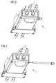
- Fig.2 shows by way of example and schematically a connection device in the closed state.
- a connection device 1 in a concrete embodiment.
- a junction box 4 is attached to a console on a bogie, a lid 5 is in the closed position and is secured with a safety device against accidental opening.
- This safety device comprises in the exemplary embodiment shown a guided through two holes of the junction box 4 rod and a locking spring.
- This safety spring is in Fig.2 already in dissolved Position shown.
- a first cable 3 leads from an actuator (in Fig.2 not shown) in the terminal device, wherein an embodiment is shown with two separate ropes.
- Figure 3 shows by way of example and schematically a connection device in the unlocked state. It is the connection device 1 from Fig.2 shown, with the securing device is completely removed.
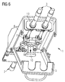
- Figure 4 shows by way of example and schematically a connecting device in the open state. It is the connection device 1 from Fig.2 illustrated, wherein the lid 5 is open. It can be seen in the interior of the junction box 4 components, the first cable 3 is connected to a first connecting element 7.
- the second cable 2 penetrates from below into the junction box 4 and is in Figure 4 partially obscured by this.
- the second cable 2 comprises two cables and two sheaths and is connected to a second connecting element 9.
- the two connecting elements 7, 9 are connected by means of a closure device 10.
- the closure device 10 is executed in the illustrated embodiment as a bolt, which penetrates through holes of the connecting elements 7, 9.
- the coats 11 of the first cable 3 are mechanically supported by means of a connecting piece 13 and thus transmits the counterforce to the force transmitted in the rope of the first cable 3 force on the connecting device 1, and the junction box 4.
- the connecting piece 13 is a plate-shaped component formed on which the jacket 11 of the first cable 3 is fixed by means of a screw connection.
- Figure 5 shows by way of example and schematically a connection device in the unlocked state. It is the connection device 1 from Fig.2 shown, wherein the closure device 10 is located in the unlocked position. In the illustrated embodiment, the closure device 10 is unlocked by a rotation of 90 degrees.
- Figure 6 shows by way of example and schematically a connecting device with removed closure element. It is the connection device 1 from Fig.2 shown, with the closure device 10 (bolt) is removed.
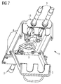
- Figure 7 shows by way of example and schematically a connection device in a separate state. It is the connection device 1 from Fig. 2 illustrated, wherein the cables 2, 3 are separated from each other.
- the first cable 3 remains fixedly connected to the connector 13, the screw of the shell 11 of the first cable 3 can remain connected, since after opening the lid 5, the positive connection of the connector 13 is lifted with the junction box 4.
Landscapes
- Engineering & Computer Science (AREA)
- Mechanical Engineering (AREA)
- General Engineering & Computer Science (AREA)
- Health & Medical Sciences (AREA)
- Oral & Maxillofacial Surgery (AREA)
- Transportation (AREA)
- Flexible Shafts (AREA)
- Handcart (AREA)
Description
- Die Erfindung betrifft eine Anschlußeinrichtung für einen Feststellbremsseilzug an einem Drehgestell eines Schienenfahrzeugs.
- Feststellbremsen von Schienenfahrzeugen, insbesondere Passagierschienenfahrzeugen werden gebräuchlicherweise von einer Betätigungseinrichtung im Wageninneren aus bedient. Diese Betätigungseinrichtung ist häufig als Handrad ausgeführt und wirkt über Kraftübertragungseinrichtungen (z.B. einen Seilzug) auf die Bremseinrichtung. Moderne Schienenfahrzeuge sind mit Scheibenbremsen ausgestattet wobei die Kraftübertragungseinrichtungen der Handbremsbetätigung parallel zu der pneumatischen Betätigung der Betriebsbremse auf die Bremsbelege wirken. Die Haltekraft der Feststellbremse ist in spezifischen Normanforderungen definiert, typischerweise muß die Feststellbremse einen Wagen mit maximal zulässiger Masse auf einem Gefälle von 35% halten können. Fahrzeuge, die für den Betrieb sowohl auf Normalspurals auch Breitspurgeleisen vorgesehen sind, müssen umfangreiche Mittel für die Austauschbarkeit der Drehgestelle aufweisen. Dabei ist auf eine rasche Austauschbarkeit besonderer Wert zu legen, da an den Austauscheinrichtungen die Mittel und Werkzeuge eines Hersteller- oder Reparaturwerks nicht zur Verfügung stehen. Die Anschlüsse und Leitungen zwischen einem Wagenkasten und einem Drehgestell müssen daher dementsprechend leicht zu trennen bzw. zu verbinden sein. Dies ist bei elektrischen und pneumatischen Anschlüssen ohne besondere Schwierigkeiten zu realisieren, die Übertragung der mechanischen Betätigungskraft für die Feststellbremse ist wesentlich aufwendiger. Gemäß dem Stand der Technik werden dabei die Mittel zur Übertragung der mechanischen Betätigungskraft (Seilzüge, Bowdenzüge, Flexballzüge) fahrwerkseitig abgeschraubt und ausgehängt. Zum Lösen und Wiederherstellen dieser Verbindung sind Sonderwerkzeuge erforderlich und der Löse- bzw. Wiederverbindungsvorgang ist sehr zeitaufwendig.
Aus der GebrauchsmusterschriftDE 203 09 134 U1 ist eine Bremsvorrichtung für ein Fahrrad bekannt, welche eine hohe Empfindlichkeit aufweist und die vordere und hintere Bremse synchron betätigt. Dazu ist eine Synchron-Gleichgewichts-Bremsvorrichtung vorgesehen, umfassend ein Gehäuse und ein Gegengewichtsstück mittels welchem die Bremsseile der vorderen und der hinteren Bremse synchron betätigbar sind. - Der Erfindung liegt daher die Aufgabe zugrunde, eine Anschlußeinrichtung für den Anschluß eines Feststellbremsseilzuges an einem Drehgestell eines Schienenfahrzeugs anzugeben, welche die Trennung und Wiederverbindung des Feststellbremsseilzuges bei einem Wechsel des Drehgestells schnell und ohne Sonderwerkzeuge ermöglicht und dabei die Verbindungsstelle vor Einflüssen der Umgebung schützt.
- Die Aufgabe wird durch eine Anschlußeinrichtung mit den Merkmalen des Anspruchs 1 und einem Schienenfahrzeug mit den Merkmalen des Anspruchs 8 gelöst. Vorteilhafte Ausgestaltungen sind Gegenstand untergeordneter Ansprüche.
- Dem Grundgedanken der Erfindung nach wird eine Anschlußeinrichtung für die Verbindung eines ersten Seilzugs mit einem zweiten Seilzug im Bereich eines Drehgestells eines Schienenfahrzeugs aufgebaut, wobei drehgestellseitig ein Anschlußkasten mit einem offenbaren Deckel angeordnet ist, und wobei ein erstes Seil des ersten Seilzugs im Inneren des Anschlußkastens mit einem ersten Verbindungselement fest verbunden ist, und ein zweites Seil des zweiten Seilzugs im Inneren des Anschlußkastens mit einem zweiten Verbindungselement fest verbunden ist, und wobei das erste Verbindungselement und das zweite Verbindungselement mittels einer formschlüssigen Verschlußeinrichtung lösbar verbunden sind, und der Deckel in geschlossener Position ein mit einem Mantel des ersten Seilzugs verbundenes Anschlußstück formschlüssig umfasst.
- Dadurch ist der Vorteil erzielbar, zwei Seilzüge so miteinander verbinden zu können, dass die von einem Seilzug eingebrachte Kraft auf den weiteren Seilzug übermittelt wird und die Seilzüge dabei einfach voneinander lösbar und wiederverbindbar sind. Insbesondere ist es vorteilhaft,
- Erfindungsgemäß ist das Seil des ersten Seilzugs, welcher die zum Betätigen der Feststellbremse erforderliche mechanische Zug- bzw. Druckkraft übermittelt mit einem Verbindungselement ausgestattet. Das Seil eines zweiten Seilzuges, welches vorgesehen ist um die vom ersten Seilzug übermittelte Kraft aufzunehmen und an die Bremseinrichtung des Drehgestells weiterzuleiten ist ebenfalls mit einem Verbindungselement ausgestattet. Diese beiden Verbindungselemente sind so gestaltet, dass sie mittels einer Verschlußeinrichtung lösbar miteinander verbindbar sind, sodass die zu übertragende mechanische Kraft über die Verbindungselemente in das jeweils korrespondierende Seil geleitet wird.
- Eine Ausführungsform der Erfindung sieht vor einen oder beide Seilzüge mit zwei parallelen Seilen auszuführen. Dadurch ist der Vorteil erzielbar, die Bremseinrichtungen beider Achsen eines zweiachsigen Drehgestells jeweils direkt mit jeweils einem Seilzug mit Kraft zu beaufschlagen, wodurch aufwendige Mechanismen zur Kraftaufteilung im Drehgestell entfallen können. Wird der Seilzug zwischen einer wagenkastenseitigen Betätigungseinrichtung (typischerweise ein Handrad) und der Anschlußeinrichtung mit zwei parallel Seilen ausgeführt, so kann auch bei Versagens eines der Seile eine Bremsung aufgeführt werden.
- Erfindungsgemäß ist der Mantel des ersten Seilzugs von der Betätigungseinrichtung zu der Anschlußeinrichtung mit einem Anschlußstück auszustatten. Dieses Anschlußstück ist fest mit dem Mantel zu verbinden, es übermittelt die Gegenkraft zu der im Seil des ersten Seilzugs übermittelten Kraft auf die Anschlußeinrichtung.
- Die Anschlußeinrichtung ist aus einem Anschlußkasten gebildet, welcher vorteilhafterweise an festen Bauteilen des Drehgestells angeordnet und mit diesen verbunden ist. Dieser Anschlußkasten ist mit einem offenbaren Deckel auszustatten, um an die in seinem Inneren befindlichen Verbindungselemente und das Verschlußelement gelangen zu können. Der zweite, zu den Bremseinrichtungen führende Seilzug ist drehgestellseitig montiert und verbleibt auch bei einem Wechsel des Drehgestells an diesem befestigt, ebenso der Anschlußkasten.
- Die Verbindung der beiden Verbindungselemente erfolgt im Inneren des Anschlußkastens mittels eines Verschlußelements. Dieses Verschlußelement ist vorteilhafterweise als Bolzen ausgebildet, welche in Eingriff mit beiden Verbindungselementen gebracht werden kann und diese solcherart formschlüssig und lösbar miteinander verbindet. Solcherart ist die Kraftübertragung zwischen den beiden Seilzügen sichergestellt.
Zur Verhinderung eines unbeabsichtigten Lösens dieser Verbindung ist das Verschlußelement vorzugsweise als Bolzen mit einer Bajonettfixierung ausgeführt. Dabei ist vor dem Herausziehen des Bolzens in Längsrichtung eine Drehung des Bolzens erforderlich, wodurch ein unbeabsichtigtes Lösen verhindert wird. Zu weiteren Steigerung der Sicherheit gegen unbeabsichtigtes Lösen kann das Verschlußelement mit weiteren Sicherungseinrichtungen ausgestattet werden. - Zur Einleitung der im ersten Seilzug geführten Zugkraft ist eine mechanische Abstützung des Anschlußstücks erforderlich, wodurch die Gegenkraft in dem ersten Seilzug auch in den Anschlußkasten geleitet wird. Dieses Anschlußstück ist erfindungsgemäß so gestaltet, dass in geschlossener Position des Deckels von diesem Deckel festgehalten wird. Dadurch ist der Vorteil erzielbar, das Anschlußstück (und solcherart den ersten Seilzug) werkzeuglos abbauen zu können.
Der zweite Seilzug weist ebenfalls ein mit seinem Mantel verbundenes Anschlußstück auf, dieses kann jedoch auf konventionelle Art (z.B. mittels Schraubverbindung) mit dem Anschlußkasten verbunden sein, da diese Verbindungsstelle bei einem Wechsel des Drehgestells nicht geöffnet werden muß. - In weiterer Fortbildung der Erfindung ist es empfehlenswert die Seilzüge als sogenannte Flexballzüge auszuführen. Diese Art von Seilzügen ermöglicht aufgrund ihrer Ausführungsform eine reibungsärmere Kraftübertragung und erlaubt auch die Übertragung von Druckkräften. Die Übertragung von Druckkräften kann erforderlich sein, da gebräuchliche Bremseinrichtungen teilweise zu geringe Rückstellkräfte aufweisen. Solcherart ist der Vorteil erzielbar, mit der Betätigungseinrichtung (Handrad im Wageninneren) ein vollständiges Öffnen der Bremse gewährleisten zu können, wodurch der Verschleiß der Bremsscheiben und Bremsbeläge reduziert wird.
- Gegenständliche Erfindung eignet sich insbesondere für den Einsatz an Schienenfahrzeugen, welche für den grenzüberschreitenden Verkehr zwischen Bahnen mit europäischer Normalspur und russischer Breitspur vorgesehen sind. Mit der hier beschriebenen Lösung kann ein sehr schnelles und werkzeugloses Trennen und Wiederverbinden des Feststellbremsanschlusses eines Drehgestells durchgeführt werden. Aufgrund der Anordnung aller wesentlichen Bauteile in einem Anschlußkasten sind die Verbindungsbauteile (Verbindungselemente, Verschlußelement) vor schädlichen Einflüssen wie Eisansatz und Steinschlag geschützt. Durch geeignete Ausführung dieses Anschlußkastens und des Deckels kann auch eine wasserdichte Umgebung für die Verbindungsbauteile geschaffen werden.
- Es zeigen beispielhaft:
-
Fig.1 Eine Anschlußeinrichtung. -
Fig.2 Anschlußeinrichtung geschlossen. -
Fig.3 Anschlußeinrichtung entriegelt. -
Fig.4 Anschlußeinrichtung geöffnet. -
Fig.5 Anschlußeinrichtung entsichert -
Fig.6 Anschlußeinrichtung Verschlußeinrichtung entfernt. -
Fig.7 Anschlußeinrichtung getrennt. -
Fig.1 zeigt beispielhaft und schematisch eine Anschlußeinrichtung. Es ist eine Anschlußeinrichtung 1 in stark abstrahierter, geschnittener Form dargestellt. Diese Anschlußeinrichtung 1 umfasst einen Anschlußkasten 4 mit einem Deckel 5. Der Deckel 5 ist beispielhaft als Klappe mit einer Drehachse ausgeführt, diese Drehachse ist im unteren Bereich des Anschlußkastens 4 angeordnet. Ein erster Seilzug 3, welcher von einer inFig.1 nicht gezeigten Betätigungseinrichtung zu der Anschlußeinrichtung 1 führt ist im oberen Bereich der Anschlußeinrichtung 1 gezeigt. Dieser erste Seilzug 3 umfasst ein erstes Seil 6 und einen dieses erste Seil 6 umgebenden ersten Mantel 11. Das Ende des ersten Seils 6 ist mit einem ersten Verbindungselement 7 verbunden. Ein zweiter Seilzug 2, welcher zu einer inFig.1 nicht dargestellten Bremseinrichtung führt, ist im unteren Bereich der Anschlußeinrichtung 1 gezeigt. Dieser zweite Seilzug 2 umfasst ein zweites Seil 8 und einen dieses zweite Seil 8 umgebenden zweiten Mantel 12. Das Ende des zweiten Seils 8 ist mit einem zweiten Verbindungselement 9 verbunden. Die Verbindungselemente 7, 9 sind so ausgeführt, dass sie untereinander eine formschlüssige lösbare Verbindung eingehen können. Das inFig.1 gezeigte prinzipielle Funktionsprinzip der Erfindung stellt dazu zwei ineinanderpassende Kreisringe dar welche mit einem Verschlußelement 10 vor unbeabsichtigtem Lösen geschützt sind. Das Verschlußelement 10 ist bolzenförmig ausgebildet und weist, inFig. 1 nicht dargestellte Ausformungen auf, welche den Formschluß der Verbindungselemente 7, 9 vor unbeabsichtigtem Lösen bewahren. Der Mantel 12 des zweiten Seilzuges 2 ist fest mit dem Anschlußkasten 4 verbunden. Der Mantel 11 des ersten Seilzugs 3 ist mit einem Anschlußstück 13 fest verbunden. Dieses Anschlußstück 13 ist bei geschlossenem Deckel 5 in Formschluß mit dem Anschlußkasten 4 und dem Deckel 5. InFig. 1 ist der Deckel 5 in geschlossener Position dargestellt. Ist der Deckel 5 geöffnet, so ist das Anschlußstück 13 und somit der mit dem Anschlußstück 13 verbundene erste Mantel 11 frei beweglich, wodurch der erste Seilzug 3 nach dem Öffnen des Verschlußelements 10 abgebaut werden kann. - Die
Fig.2 bis 7 zeigen die Arbeitsschritte eines Trennvorgangs einer Anschlußeinrichtung. Das Verbinden erfolgt in entgegengesetzter Reihenfolge der Arbeitsschritte. -
Fig.2 zeigt beispielhaft und schematisch eine Anschlußeinrichtung in geschlossenem Zustand. Es ist eine Anschlußeinrichtung 1 in einer konkreten Ausführung gezeigt. Ein Anschlußkasten 4 ist an einer Konsole an einem Drehgestell befestigt, ein Deckel 5 befindet sich in geschlossener Position und ist mit einer Sicherungseinrichtung vor ungewolltem Öffnen gesichert. Diese Sicherungseinrichtung umfasst in gezeigtem Ausführungsbeispiel einen durch zwei Bohrungen des Anschlußkastens 4 geführten Stab und eine Sicherungsfeder. Diese Sicherungsfeder ist inFig.2 bereits in gelöster Position gezeigt. Ein erster Seilzug 3 führt von einer Betätigungseinrichtung (inFig.2 nicht dargestellt) in die Anschlußeinrichtung, wobei eine Ausführungsform mit zwei getrennten Seilen dargestellt ist. -
Fig.3 zeigt beispielhaft und schematisch eine Anschlußeinrichtung in entriegeltem Zustand. Es ist die Anschlußeinrichtung 1 ausFig.2 dargestellt, wobei die Sicherungseinrichtung vollständig entfernt ist. -
Fig.4 zeigt beispielhaft und schematisch eine Anschlußeinrichtung in geöffnetem Zustand. Es ist die Anschlußeinrichtung 1 ausFig.2 dargestellt, wobei der Deckel 5 geöffnet ist. Es sind die im Inneren des Anschlußkastens 4 befindlichen Bauteile erkennbar, wobei der erste Seilzug 3 mit einem ersten Verbindungselement 7 verbunden ist. Der zweite Seilzug 2 dringt von unten in den Anschlußkasten 4 ein und ist inFig.4 von diesem teilweise verdeckt. Der zweite Seilzug 2 umfasst zwei Seile und zwei Mäntel und ist mit einem zweiten Verbindungselement 9 verbunden. Die beiden Verbindungselemente 7, 9 sind mittels einer Verschlußeinrichtung 10 verbunden. Die Verschlußeinrichtung 10 ist in gezeigtem Ausführungsbeispiel als Bolzen ausgeführt, welcher durch Bohrungen der Verbindungselemente 7, 9 dringt. Die Mäntel 11 des ersten Seilzugs 3 sind mittels eines Anschlußstücks 13 mechanisch abgestützt und übermittelt so die Gegenkraft zu der im Seil des ersten Seilzugs 3 übermittelten Kraft auf die Anschlußeinrichtung 1, bzw. den Anschlußkasten 4. In gezeigtem Ausführungsbeispiel ist das Anschlußstück 13 als plattenförmiges Bauteil ausgebildet, an welchem der Mantel 11 des ersten Seilzugs 3 mittels einer Schraubverbindung befestigt ist. -
Fig.5 zeigt beispielhaft und schematisch eine Anschlußeinrichtung in entsichertem Zustand. Es ist die Anschlußeinrichtung 1 ausFig.2 dargestellt, wobei die Verschlußeinrichtung 10 in entsicherter Position befindlich ist. In gezeigtem Ausführungsbeispiel ist die Verschlußeinrichtung 10 mittels einer Drehung um 90 Grad entsichert. -
Fig.6 zeigt beispielhaft und schematisch eine Anschlußeinrichtung mit entferntem Verschlußelement. Es ist die Anschlußeinrichtung 1 ausFig.2 dargestellt, wobei die Verschlußeinrichtung 10 (Bolzen) entfernt ist. -
Fig.7 zeigt beispielhaft und schematisch eine Anschlußeinrichtung in getrenntem Zustand. Es ist die Anschlußeinrichtung 1 ausFig. 2 dargestellt, wobei die Seilzüge 2, 3 voneinander getrennt sind. Der erste Seilzug 3 verbleibt mit dem Anschlußstück 13 fest verbunden, die Schraubverbindungen des Mantels 11 des ersten Seilzugs 3 können verbunden bleiben, da nach dem Öffnen des Deckels 5 die formschlüssige Verbindung des Anschlußstücks 13 mit dem Anschlußkasten 4 aufgehoben wird. -
- 1
- Anschlußeinrichtung
- 2
- Zweiter Seilzug
- 3
- Erster Seilzug
- 4
- Anschlußkasten
- 5
- Deckel
- 6
- Erstes Seil
- 7
- Erstes Verbindungselement
- 8
- Zweites Seil
- 9
- Zweites Verbindungselement
- 10
- Verschlußeinrichtung
- 11
- Erster Mantel
- 12
- Zweiter Mantel
- 13
- Anschlußstück
Claims (9)
- Anschlußeinrichtung (1) für die Verbindung eines ersten Seilzugs (3) mit einem zweiten Seilzug (2) im Bereich eines Drehgestells eines Schienenfahrzeugs, dadurch gekennzeichnet, dass drehgestellseitig ein Anschlußkasten (4) mit einem offenbaren Deckel (5) angeordnet ist, und das ein erstes Seil (6) des ersten Seilzugs (3) im Inneren des Anschlußkastens (4) mit einem ersten Verbindungselement (7) fest verbunden ist, und
ein zweites Seil (8) des zweiten Seilzugs (2) im Inneren des Anschlußkastens (4) mit einem zweiten Verbindungselement (9) fest verbunden ist, und
das erste Verbindungselement (7) und das zweite Verbindungslement (9) mittels einer formschlüssigen Verschlußeinrichtung (10) lösbar verbunden sind, und der Deckel (5) in geschlossener Position ein mit einem Mantel (11) des ersten Seilzugs (3) verbundenes Anschlußstück (13) formschlüssig umfasst. - Anschlußeinrichtung (1) nach Anspruch 1, dadurch gekennzeichnet, dass der erste Seilzug (3) oder der zweite Seilzug (2) als Doppelseilzug mit zwei Seilen und zwei Mänteln ausgeführt ist.
- Anschlußeinrichtung (1) nach einem der Ansprüche 1 oder 2, dadurch gekennzeichnet, dass der erste Seilzug (3) oder der zweite Seilzug (2) als Bowdenzug nach Art des Flexballzuges ausgeführt ist.
- Anschlußeinrichtung (1) nach einem der Ansprüche 1 bis 3, dadurch gekennzeichnet, dass der Deckel (5) als Klappe mit einer Drehachse ausgeführt ist.
- Anschlußeinrichtung (1) nach einem der Ansprüche 1 bis 4, dadurch gekennzeichnet, dass die Verschlußeinrichtung (10) als Bolzen mit einer Bajonettfixierung ausgeführt ist.
- Anschlußeinrichtung (1) nach einem der Ansprüche 1 bis 5, dadurch gekennzeichnet, dass der erste Seilzug (3) die mechanische Betätigungskraft für eine Feststellbremse von einer wagenkastenseitigen Betätigungseinrichtung übermittelt und der zweite Seilzug (2) diese mechanische Betätigungskraft an eine Bremseinrichtung eines Drehgestells übermittelt.
- Anschlußeinrichtung (1) nach einem der Ansprüche 1 bis 6, dadurch gekennzeichnet, dass der zweite Seilzug (2) aus zwei Bowdenzügen gebildet ist, wobei je ein Seilzug die mechanische Betätigungskraft zu einer Bremseinrichtung einer Achse des Drehgestells übermittelt.
- Schienenfahrzeug, umfassend eine Anschlußeinrichtung nach einem der Ansprüche 1 bis 7.
- Schienenfahrzeug nach Anspruch 8, dadurch gekennzeichnet, dass die Drehgestelle austauschbar sind, wobei Drehgestelle gemäß der europäischen Normalspur oder der russischen Breitspur an dem Schienenfahrzeug befestigbar sind.
Priority Applications (1)
| Application Number | Priority Date | Filing Date | Title |
|---|---|---|---|
| PL14702519T PL2953829T3 (pl) | 2013-02-06 | 2014-01-28 | Urządzenie przyłączeniowe |
Applications Claiming Priority (2)
| Application Number | Priority Date | Filing Date | Title |
|---|---|---|---|
| ATA50090/2013A AT513601B1 (de) | 2013-02-06 | 2013-02-06 | Anschlußeinrichtung |
| PCT/EP2014/051651 WO2014122047A1 (de) | 2013-02-06 | 2014-01-28 | Anschlusseinrichtung |
Publications (2)
| Publication Number | Publication Date |
|---|---|
| EP2953829A1 EP2953829A1 (de) | 2015-12-16 |
| EP2953829B1 true EP2953829B1 (de) | 2016-11-23 |
Family
ID=50033509
Family Applications (1)
| Application Number | Title | Priority Date | Filing Date |
|---|---|---|---|
| EP14702519.1A Active EP2953829B1 (de) | 2013-02-06 | 2014-01-28 | Anschlusseinrichtung |
Country Status (5)
| Country | Link |
|---|---|
| EP (1) | EP2953829B1 (de) |
| AT (1) | AT513601B1 (de) |
| PL (1) | PL2953829T3 (de) |
| RU (1) | RU2646199C2 (de) |
| WO (1) | WO2014122047A1 (de) |
Families Citing this family (1)
| Publication number | Priority date | Publication date | Assignee | Title |
|---|---|---|---|---|
| JP6598293B2 (ja) * | 2015-07-23 | 2019-10-30 | 株式会社ハイレックスコーポレーション | ケーブルジョイント、および、これを備えたケーブル操作機構 |
Family Cites Families (10)
| Publication number | Priority date | Publication date | Assignee | Title |
|---|---|---|---|---|
| US4766980A (en) * | 1985-09-16 | 1988-08-30 | General Signal Corporation | Rail car brake apparatus |
| TW322458B (en) * | 1997-05-10 | 1997-12-11 | Chii-Chau Liaw | Safety apparatus of brake of a bicycle |
| US5947236A (en) * | 1997-06-13 | 1999-09-07 | New York Air Brake Corporation | Truck mounted brake for standard and premium ride trucks |
| DE19853656B4 (de) * | 1998-11-20 | 2005-12-08 | Fico Cables, S.A., Rubi | Verbindungseinheit |
| FR2790724B1 (fr) * | 1999-03-12 | 2001-04-13 | Renault | Dispositif d'actionnement de freins de stationnement de vehicule automobile |
| CA2434590C (en) * | 2002-08-07 | 2006-12-19 | New York Air Brake Corporation | A parking brake for a rail vehicle |
| DE20309134U1 (de) * | 2003-06-12 | 2003-08-14 | Chun, Te Wen, Taichung | Synchron-Gleichgewichts-Bremsvorrichtung für ein Fahrrad |
| WO2008094991A2 (en) * | 2007-01-31 | 2008-08-07 | Wabtec Holding Corp. | Parking brake assembly for railway vehicle brake system |
| TWM412127U (en) * | 2011-01-31 | 2011-09-21 | Ren-Fa Luo | Improved front and rear wheel brake control device |
| CN104470784B (zh) * | 2011-12-27 | 2018-06-01 | 西屋公司 | 集成转向架制动器及用于该集成转向架制动器的调整臂 |
-
2013
- 2013-02-06 AT ATA50090/2013A patent/AT513601B1/de not_active IP Right Cessation
-
2014
- 2014-01-28 RU RU2015132760A patent/RU2646199C2/ru active
- 2014-01-28 EP EP14702519.1A patent/EP2953829B1/de active Active
- 2014-01-28 WO PCT/EP2014/051651 patent/WO2014122047A1/de not_active Ceased
- 2014-01-28 PL PL14702519T patent/PL2953829T3/pl unknown
Also Published As
| Publication number | Publication date |
|---|---|
| WO2014122047A1 (de) | 2014-08-14 |
| RU2015132760A (ru) | 2017-03-09 |
| AT513601B1 (de) | 2014-06-15 |
| PL2953829T3 (pl) | 2017-05-31 |
| RU2646199C2 (ru) | 2018-03-01 |
| EP2953829A1 (de) | 2015-12-16 |
| AT513601A4 (de) | 2014-06-15 |
Similar Documents
| Publication | Publication Date | Title |
|---|---|---|
| EP0975498B1 (de) | Feststellbremsanlage für fahrzeuge | |
| EP2334534B1 (de) | Mittelpufferkupplung für schienengebundene fahrzeuge | |
| DE202012101639U1 (de) | Durchführungsgehäuse | |
| WO2013149786A1 (de) | Bugklappenanordnung für spurgeführte fahrzeuge | |
| DE102009011904A1 (de) | Verbindungsvorrichtung | |
| EP2367248A2 (de) | Medienversorgungsvorrichtung zur Bereitstellung und Entsorgung von Medien | |
| EP3165495B1 (de) | Turmdrehkran | |
| DE102016206989A1 (de) | Lagerbockanordnung | |
| DE102017001943A1 (de) | Anschlusssystem | |
| EP2953829B1 (de) | Anschlusseinrichtung | |
| EP3607641B1 (de) | Stellantrieb mit bremsvorrichtung | |
| DE102010031924A1 (de) | System zur Befestigung eines Luftfahrzeugsitzes | |
| WO2015155287A1 (de) | Steuereinrichtung | |
| DE102009050932A1 (de) | Anhängerkupplungseinrichtung für einen Kraftwagen | |
| WO2017202462A1 (de) | Feststellbremse für ein fahrwerk eines schienenfahrzeugs | |
| AT519362B1 (de) | Schienenfahrzeugkupplung für die Verbindung zweier Schienenfahrzeuge | |
| DE102024112185B3 (de) | Ladebuchseneinrichtung für ein Kraftfahrzeug und Verfahren zur Notentriegelung einer Ladesteckverbindung | |
| DE4315089C2 (de) | Schnellverschlußkupplungskopf für Schienenfahrzeuge | |
| AT524931B1 (de) | Wagenkasten für ein Schienenfahrzeug | |
| AT513899B1 (de) | Passagierschienenfahrzeug | |
| DE102017109045A1 (de) | Leitungshalter für ein kraftfahrezug und damit ausgestattete leitungsanordnung | |
| DE102016118531A1 (de) | Scharnieranordnung für eine Fahrzeugkomponente | |
| DE202011051666U1 (de) | Vorrichtung zur Positionserfassung einer Aufzugkabine | |
| WO2018149434A1 (de) | Doppelbedienung für fahrschulfahrzeuge mit entkopplungsvorrichtungen für die zusatzpedale | |
| AT522333A4 (de) | Notlösevorrichtung für eine Fahrzeugbremse |
Legal Events
| Date | Code | Title | Description |
|---|---|---|---|
| PUAI | Public reference made under article 153(3) epc to a published international application that has entered the european phase |
Free format text: ORIGINAL CODE: 0009012 |
|
| 17P | Request for examination filed |
Effective date: 20150612 |
|
| AK | Designated contracting states |
Kind code of ref document: A1 Designated state(s): AL AT BE BG CH CY CZ DE DK EE ES FI FR GB GR HR HU IE IS IT LI LT LU LV MC MK MT NL NO PL PT RO RS SE SI SK SM TR |
|
| AX | Request for extension of the european patent |
Extension state: BA ME |
|
| REG | Reference to a national code |
Ref country code: DE Ref legal event code: R079 Ref document number: 502014002037 Country of ref document: DE Free format text: PREVIOUS MAIN CLASS: B60T0011060000 Ipc: B61H0013000000 |
|
| DAX | Request for extension of the european patent (deleted) | ||
| RIC1 | Information provided on ipc code assigned before grant |
Ipc: B61H 13/00 20060101AFI20160504BHEP |
|
| GRAP | Despatch of communication of intention to grant a patent |
Free format text: ORIGINAL CODE: EPIDOSNIGR1 |
|
| INTG | Intention to grant announced |
Effective date: 20160620 |
|
| GRAS | Grant fee paid |
Free format text: ORIGINAL CODE: EPIDOSNIGR3 |
|
| GRAA | (expected) grant |
Free format text: ORIGINAL CODE: 0009210 |
|
| AK | Designated contracting states |
Kind code of ref document: B1 Designated state(s): AL AT BE BG CH CY CZ DE DK EE ES FI FR GB GR HR HU IE IS IT LI LT LU LV MC MK MT NL NO PL PT RO RS SE SI SK SM TR |
|
| REG | Reference to a national code |
Ref country code: GB Ref legal event code: FG4D Free format text: NOT ENGLISH |
|
| REG | Reference to a national code |
Ref country code: CH Ref legal event code: EP |
|
| REG | Reference to a national code |
Ref country code: IE Ref legal event code: FG4D Free format text: LANGUAGE OF EP DOCUMENT: GERMAN |
|
| REG | Reference to a national code |
Ref country code: AT Ref legal event code: REF Ref document number: 847577 Country of ref document: AT Kind code of ref document: T Effective date: 20161215 |
|
| REG | Reference to a national code |
Ref country code: DE Ref legal event code: R096 Ref document number: 502014002037 Country of ref document: DE |
|
| PG25 | Lapsed in a contracting state [announced via postgrant information from national office to epo] |
Ref country code: LV Free format text: LAPSE BECAUSE OF FAILURE TO SUBMIT A TRANSLATION OF THE DESCRIPTION OR TO PAY THE FEE WITHIN THE PRESCRIBED TIME-LIMIT Effective date: 20161123 |
|
| REG | Reference to a national code |
Ref country code: LT Ref legal event code: MG4D |
|
| REG | Reference to a national code |
Ref country code: NL Ref legal event code: MP Effective date: 20161123 |
|
| PG25 | Lapsed in a contracting state [announced via postgrant information from national office to epo] |
Ref country code: NO Free format text: LAPSE BECAUSE OF FAILURE TO SUBMIT A TRANSLATION OF THE DESCRIPTION OR TO PAY THE FEE WITHIN THE PRESCRIBED TIME-LIMIT Effective date: 20170223 Ref country code: LT Free format text: LAPSE BECAUSE OF FAILURE TO SUBMIT A TRANSLATION OF THE DESCRIPTION OR TO PAY THE FEE WITHIN THE PRESCRIBED TIME-LIMIT Effective date: 20161123 Ref country code: GR Free format text: LAPSE BECAUSE OF FAILURE TO SUBMIT A TRANSLATION OF THE DESCRIPTION OR TO PAY THE FEE WITHIN THE PRESCRIBED TIME-LIMIT Effective date: 20170224 Ref country code: SE Free format text: LAPSE BECAUSE OF FAILURE TO SUBMIT A TRANSLATION OF THE DESCRIPTION OR TO PAY THE FEE WITHIN THE PRESCRIBED TIME-LIMIT Effective date: 20161123 Ref country code: NL Free format text: LAPSE BECAUSE OF FAILURE TO SUBMIT A TRANSLATION OF THE DESCRIPTION OR TO PAY THE FEE WITHIN THE PRESCRIBED TIME-LIMIT Effective date: 20161123 |
|
| PG25 | Lapsed in a contracting state [announced via postgrant information from national office to epo] |
Ref country code: BE Free format text: LAPSE BECAUSE OF NON-PAYMENT OF DUE FEES Effective date: 20170131 Ref country code: PT Free format text: LAPSE BECAUSE OF FAILURE TO SUBMIT A TRANSLATION OF THE DESCRIPTION OR TO PAY THE FEE WITHIN THE PRESCRIBED TIME-LIMIT Effective date: 20170323 Ref country code: ES Free format text: LAPSE BECAUSE OF FAILURE TO SUBMIT A TRANSLATION OF THE DESCRIPTION OR TO PAY THE FEE WITHIN THE PRESCRIBED TIME-LIMIT Effective date: 20161123 Ref country code: HR Free format text: LAPSE BECAUSE OF FAILURE TO SUBMIT A TRANSLATION OF THE DESCRIPTION OR TO PAY THE FEE WITHIN THE PRESCRIBED TIME-LIMIT Effective date: 20161123 Ref country code: FI Free format text: LAPSE BECAUSE OF FAILURE TO SUBMIT A TRANSLATION OF THE DESCRIPTION OR TO PAY THE FEE WITHIN THE PRESCRIBED TIME-LIMIT Effective date: 20161123 Ref country code: RS Free format text: LAPSE BECAUSE OF FAILURE TO SUBMIT A TRANSLATION OF THE DESCRIPTION OR TO PAY THE FEE WITHIN THE PRESCRIBED TIME-LIMIT Effective date: 20161123 |
|
| PG25 | Lapsed in a contracting state [announced via postgrant information from national office to epo] |
Ref country code: EE Free format text: LAPSE BECAUSE OF FAILURE TO SUBMIT A TRANSLATION OF THE DESCRIPTION OR TO PAY THE FEE WITHIN THE PRESCRIBED TIME-LIMIT Effective date: 20161123 Ref country code: DK Free format text: LAPSE BECAUSE OF FAILURE TO SUBMIT A TRANSLATION OF THE DESCRIPTION OR TO PAY THE FEE WITHIN THE PRESCRIBED TIME-LIMIT Effective date: 20161123 Ref country code: RO Free format text: LAPSE BECAUSE OF FAILURE TO SUBMIT A TRANSLATION OF THE DESCRIPTION OR TO PAY THE FEE WITHIN THE PRESCRIBED TIME-LIMIT Effective date: 20161123 |
|
| REG | Reference to a national code |
Ref country code: DE Ref legal event code: R097 Ref document number: 502014002037 Country of ref document: DE |
|
| PG25 | Lapsed in a contracting state [announced via postgrant information from national office to epo] |
Ref country code: IT Free format text: LAPSE BECAUSE OF FAILURE TO SUBMIT A TRANSLATION OF THE DESCRIPTION OR TO PAY THE FEE WITHIN THE PRESCRIBED TIME-LIMIT Effective date: 20161123 Ref country code: SM Free format text: LAPSE BECAUSE OF FAILURE TO SUBMIT A TRANSLATION OF THE DESCRIPTION OR TO PAY THE FEE WITHIN THE PRESCRIBED TIME-LIMIT Effective date: 20161123 Ref country code: BG Free format text: LAPSE BECAUSE OF FAILURE TO SUBMIT A TRANSLATION OF THE DESCRIPTION OR TO PAY THE FEE WITHIN THE PRESCRIBED TIME-LIMIT Effective date: 20170223 |
|
| REG | Reference to a national code |
Ref country code: CH Ref legal event code: PL |
|
| PG25 | Lapsed in a contracting state [announced via postgrant information from national office to epo] |
Ref country code: MC Free format text: LAPSE BECAUSE OF FAILURE TO SUBMIT A TRANSLATION OF THE DESCRIPTION OR TO PAY THE FEE WITHIN THE PRESCRIBED TIME-LIMIT Effective date: 20161123 |
|
| PLBE | No opposition filed within time limit |
Free format text: ORIGINAL CODE: 0009261 |
|
| STAA | Information on the status of an ep patent application or granted ep patent |
Free format text: STATUS: NO OPPOSITION FILED WITHIN TIME LIMIT |
|
| REG | Reference to a national code |
Ref country code: FR Ref legal event code: ST Effective date: 20170929 |
|
| PG25 | Lapsed in a contracting state [announced via postgrant information from national office to epo] |
Ref country code: CH Free format text: LAPSE BECAUSE OF NON-PAYMENT OF DUE FEES Effective date: 20170131 Ref country code: LI Free format text: LAPSE BECAUSE OF NON-PAYMENT OF DUE FEES Effective date: 20170131 Ref country code: FR Free format text: LAPSE BECAUSE OF NON-PAYMENT OF DUE FEES Effective date: 20170131 |
|
| 26N | No opposition filed |
Effective date: 20170824 |
|
| REG | Reference to a national code |
Ref country code: IE Ref legal event code: MM4A |
|
| PG25 | Lapsed in a contracting state [announced via postgrant information from national office to epo] |
Ref country code: LU Free format text: LAPSE BECAUSE OF NON-PAYMENT OF DUE FEES Effective date: 20170128 Ref country code: SI Free format text: LAPSE BECAUSE OF FAILURE TO SUBMIT A TRANSLATION OF THE DESCRIPTION OR TO PAY THE FEE WITHIN THE PRESCRIBED TIME-LIMIT Effective date: 20161123 |
|
| REG | Reference to a national code |
Ref country code: BE Ref legal event code: MM Effective date: 20170131 |
|
| PG25 | Lapsed in a contracting state [announced via postgrant information from national office to epo] |
Ref country code: IE Free format text: LAPSE BECAUSE OF NON-PAYMENT OF DUE FEES Effective date: 20170128 |
|
| GBPC | Gb: european patent ceased through non-payment of renewal fee |
Effective date: 20180128 |
|
| PG25 | Lapsed in a contracting state [announced via postgrant information from national office to epo] |
Ref country code: MT Free format text: LAPSE BECAUSE OF FAILURE TO SUBMIT A TRANSLATION OF THE DESCRIPTION OR TO PAY THE FEE WITHIN THE PRESCRIBED TIME-LIMIT Effective date: 20161123 |
|
| PG25 | Lapsed in a contracting state [announced via postgrant information from national office to epo] |
Ref country code: GB Free format text: LAPSE BECAUSE OF NON-PAYMENT OF DUE FEES Effective date: 20180128 |
|
| REG | Reference to a national code |
Ref country code: DE Ref legal event code: R082 Ref document number: 502014002037 Country of ref document: DE Representative=s name: DEFFNER, ROLF, DR., DE Ref country code: DE Ref legal event code: R081 Ref document number: 502014002037 Country of ref document: DE Owner name: SIEMENS MOBILITY GMBH, AT Free format text: FORMER OWNER: SIEMENS AG OESTERREICH, WIEN, AT Ref country code: DE Ref legal event code: R081 Ref document number: 502014002037 Country of ref document: DE Owner name: SIEMENS MOBILITY AUSTRIA GMBH, AT Free format text: FORMER OWNER: SIEMENS AG OESTERREICH, WIEN, AT |
|
| PG25 | Lapsed in a contracting state [announced via postgrant information from national office to epo] |
Ref country code: HU Free format text: LAPSE BECAUSE OF FAILURE TO SUBMIT A TRANSLATION OF THE DESCRIPTION OR TO PAY THE FEE WITHIN THE PRESCRIBED TIME-LIMIT; INVALID AB INITIO Effective date: 20140128 |
|
| REG | Reference to a national code |
Ref country code: AT Ref legal event code: PC Ref document number: 847577 Country of ref document: AT Kind code of ref document: T Owner name: SIEMENS MOBILITY GMBH, AT Effective date: 20190814 |
|
| PG25 | Lapsed in a contracting state [announced via postgrant information from national office to epo] |
Ref country code: CY Free format text: LAPSE BECAUSE OF FAILURE TO SUBMIT A TRANSLATION OF THE DESCRIPTION OR TO PAY THE FEE WITHIN THE PRESCRIBED TIME-LIMIT Effective date: 20161123 |
|
| PG25 | Lapsed in a contracting state [announced via postgrant information from national office to epo] |
Ref country code: MK Free format text: LAPSE BECAUSE OF FAILURE TO SUBMIT A TRANSLATION OF THE DESCRIPTION OR TO PAY THE FEE WITHIN THE PRESCRIBED TIME-LIMIT Effective date: 20161123 |
|
| REG | Reference to a national code |
Ref country code: DE Ref legal event code: R082 Ref document number: 502014002037 Country of ref document: DE Representative=s name: DEFFNER, ROLF, DR., DE Ref country code: DE Ref legal event code: R081 Ref document number: 502014002037 Country of ref document: DE Owner name: SIEMENS MOBILITY AUSTRIA GMBH, AT Free format text: FORMER OWNER: SIEMENS MOBILITY GMBH, WIEN, AT |
|
| REG | Reference to a national code |
Ref country code: SK Ref legal event code: PC4A Ref document number: E 23498 Country of ref document: SK Owner name: SIEMENS MOBILITY AUSTRIA GMBH, WIEN, AT Free format text: FORMER OWNER: SIEMENS AG OESTERREICH, WIEN, AT Effective date: 20200302 |
|
| PG25 | Lapsed in a contracting state [announced via postgrant information from national office to epo] |
Ref country code: AL Free format text: LAPSE BECAUSE OF FAILURE TO SUBMIT A TRANSLATION OF THE DESCRIPTION OR TO PAY THE FEE WITHIN THE PRESCRIBED TIME-LIMIT Effective date: 20161123 Ref country code: IS Free format text: LAPSE BECAUSE OF FAILURE TO SUBMIT A TRANSLATION OF THE DESCRIPTION OR TO PAY THE FEE WITHIN THE PRESCRIBED TIME-LIMIT Effective date: 20170323 |
|
| REG | Reference to a national code |
Ref country code: AT Ref legal event code: HC Ref document number: 847577 Country of ref document: AT Kind code of ref document: T Owner name: SIEMENS MOBILITY AUSTRIA GMBH, AT Effective date: 20211108 |
|
| PGFP | Annual fee paid to national office [announced via postgrant information from national office to epo] |
Ref country code: SK Payment date: 20240123 Year of fee payment: 11 |
|
| PGFP | Annual fee paid to national office [announced via postgrant information from national office to epo] |
Ref country code: PL Payment date: 20250117 Year of fee payment: 12 Ref country code: CZ Payment date: 20250120 Year of fee payment: 12 |
|
| PGFP | Annual fee paid to national office [announced via postgrant information from national office to epo] |
Ref country code: TR Payment date: 20250120 Year of fee payment: 12 |
|
| REG | Reference to a national code |
Ref country code: SK Ref legal event code: MM4A Ref document number: E 23498 Country of ref document: SK Effective date: 20250128 |
|
| PG25 | Lapsed in a contracting state [announced via postgrant information from national office to epo] |
Ref country code: SK Free format text: LAPSE BECAUSE OF NON-PAYMENT OF DUE FEES Effective date: 20250128 |
|
| PGFP | Annual fee paid to national office [announced via postgrant information from national office to epo] |
Ref country code: DE Payment date: 20260320 Year of fee payment: 13 |
|
| PGFP | Annual fee paid to national office [announced via postgrant information from national office to epo] |
Ref country code: AT Payment date: 20251210 Year of fee payment: 13 |