EP2953786B1 - Verfahren und vorrichtung zur überarbeitung von strukturen - Google Patents
Verfahren und vorrichtung zur überarbeitung von strukturen Download PDFInfo
- Publication number
- EP2953786B1 EP2953786B1 EP14702330.3A EP14702330A EP2953786B1 EP 2953786 B1 EP2953786 B1 EP 2953786B1 EP 14702330 A EP14702330 A EP 14702330A EP 2953786 B1 EP2953786 B1 EP 2953786B1
- Authority
- EP
- European Patent Office
- Prior art keywords
- patch
- resin
- vacuum
- hollow needle
- vacuum bag
- Prior art date
- Legal status (The legal status is an assumption and is not a legal conclusion. Google has not performed a legal analysis and makes no representation as to the accuracy of the status listed.)
- Active
Links
- 238000000034 method Methods 0.000 title claims description 93
- 239000011347 resin Substances 0.000 claims description 171
- 229920005989 resin Polymers 0.000 claims description 171
- 239000000835 fiber Substances 0.000 claims description 101
- 238000001802 infusion Methods 0.000 claims description 23
- 239000002131 composite material Substances 0.000 claims description 19
- 238000007789 sealing Methods 0.000 claims description 8
- 230000035515 penetration Effects 0.000 claims description 7
- 230000002708 enhancing effect Effects 0.000 claims description 6
- 238000003780 insertion Methods 0.000 claims description 3
- 230000037431 insertion Effects 0.000 claims description 3
- 238000004519 manufacturing process Methods 0.000 description 9
- 238000010586 diagram Methods 0.000 description 6
- 230000008569 process Effects 0.000 description 6
- 239000000565 sealant Substances 0.000 description 6
- 230000008439 repair process Effects 0.000 description 5
- 238000005056 compaction Methods 0.000 description 4
- 230000008878 coupling Effects 0.000 description 4
- 238000010168 coupling process Methods 0.000 description 4
- 238000005859 coupling reaction Methods 0.000 description 4
- 238000012423 maintenance Methods 0.000 description 4
- 230000002787 reinforcement Effects 0.000 description 4
- 239000000853 adhesive Substances 0.000 description 3
- 230000001070 adhesive effect Effects 0.000 description 3
- 238000013461 design Methods 0.000 description 3
- 239000000463 material Substances 0.000 description 3
- 230000004048 modification Effects 0.000 description 3
- 238000012986 modification Methods 0.000 description 3
- 239000003039 volatile agent Substances 0.000 description 3
- 238000009756 wet lay-up Methods 0.000 description 3
- 239000004744 fabric Substances 0.000 description 2
- 239000011152 fibreglass Substances 0.000 description 2
- 230000003014 reinforcing effect Effects 0.000 description 2
- 239000004677 Nylon Substances 0.000 description 1
- 229920006362 Teflon® Polymers 0.000 description 1
- 239000000919 ceramic Substances 0.000 description 1
- 125000004122 cyclic group Chemical group 0.000 description 1
- 230000000694 effects Effects 0.000 description 1
- 230000007613 environmental effect Effects 0.000 description 1
- 238000009787 hand lay-up Methods 0.000 description 1
- 230000010354 integration Effects 0.000 description 1
- 230000007246 mechanism Effects 0.000 description 1
- 239000002184 metal Substances 0.000 description 1
- 229910052751 metal Inorganic materials 0.000 description 1
- 239000002905 metal composite material Substances 0.000 description 1
- 150000002739 metals Chemical class 0.000 description 1
- 229920001778 nylon Polymers 0.000 description 1
- 230000008520 organization Effects 0.000 description 1
- 230000009467 reduction Effects 0.000 description 1
- 238000009419 refurbishment Methods 0.000 description 1
- 238000000926 separation method Methods 0.000 description 1
- 238000012546 transfer Methods 0.000 description 1
- 239000002759 woven fabric Substances 0.000 description 1
Images


Classifications
-
- B—PERFORMING OPERATIONS; TRANSPORTING
- B29—WORKING OF PLASTICS; WORKING OF SUBSTANCES IN A PLASTIC STATE IN GENERAL
- B29C—SHAPING OR JOINING OF PLASTICS; SHAPING OF MATERIAL IN A PLASTIC STATE, NOT OTHERWISE PROVIDED FOR; AFTER-TREATMENT OF THE SHAPED PRODUCTS, e.g. REPAIRING
- B29C70/00—Shaping composites, i.e. plastics material comprising reinforcements, fillers or preformed parts, e.g. inserts
- B29C70/04—Shaping composites, i.e. plastics material comprising reinforcements, fillers or preformed parts, e.g. inserts comprising reinforcements only, e.g. self-reinforcing plastics
- B29C70/28—Shaping operations therefor
- B29C70/54—Component parts, details or accessories; Auxiliary operations, e.g. feeding or storage of prepregs or SMC after impregnation or during ageing
- B29C70/544—Details of vacuum bags, e.g. materials or shape
-
- B—PERFORMING OPERATIONS; TRANSPORTING
- B32—LAYERED PRODUCTS
- B32B—LAYERED PRODUCTS, i.e. PRODUCTS BUILT-UP OF STRATA OF FLAT OR NON-FLAT, e.g. CELLULAR OR HONEYCOMB, FORM
- B32B38/00—Ancillary operations in connection with laminating processes
- B32B38/08—Impregnating
-
- B—PERFORMING OPERATIONS; TRANSPORTING
- B29—WORKING OF PLASTICS; WORKING OF SUBSTANCES IN A PLASTIC STATE IN GENERAL
- B29C—SHAPING OR JOINING OF PLASTICS; SHAPING OF MATERIAL IN A PLASTIC STATE, NOT OTHERWISE PROVIDED FOR; AFTER-TREATMENT OF THE SHAPED PRODUCTS, e.g. REPAIRING
- B29C70/00—Shaping composites, i.e. plastics material comprising reinforcements, fillers or preformed parts, e.g. inserts
- B29C70/04—Shaping composites, i.e. plastics material comprising reinforcements, fillers or preformed parts, e.g. inserts comprising reinforcements only, e.g. self-reinforcing plastics
- B29C70/28—Shaping operations therefor
- B29C70/40—Shaping or impregnating by compression not applied
- B29C70/42—Shaping or impregnating by compression not applied for producing articles of definite length, i.e. discrete articles
- B29C70/44—Shaping or impregnating by compression not applied for producing articles of definite length, i.e. discrete articles using isostatic pressure, e.g. pressure difference-moulding, vacuum bag-moulding, autoclave-moulding or expanding rubber-moulding
- B29C70/443—Shaping or impregnating by compression not applied for producing articles of definite length, i.e. discrete articles using isostatic pressure, e.g. pressure difference-moulding, vacuum bag-moulding, autoclave-moulding or expanding rubber-moulding and impregnating by vacuum or injection
-
- B—PERFORMING OPERATIONS; TRANSPORTING
- B29—WORKING OF PLASTICS; WORKING OF SUBSTANCES IN A PLASTIC STATE IN GENERAL
- B29C—SHAPING OR JOINING OF PLASTICS; SHAPING OF MATERIAL IN A PLASTIC STATE, NOT OTHERWISE PROVIDED FOR; AFTER-TREATMENT OF THE SHAPED PRODUCTS, e.g. REPAIRING
- B29C73/00—Repairing of articles made from plastics or substances in a plastic state, e.g. of articles shaped or produced by using techniques covered by this subclass or subclass B29D
- B29C73/04—Repairing of articles made from plastics or substances in a plastic state, e.g. of articles shaped or produced by using techniques covered by this subclass or subclass B29D using preformed elements
- B29C73/10—Repairing of articles made from plastics or substances in a plastic state, e.g. of articles shaped or produced by using techniques covered by this subclass or subclass B29D using preformed elements using patches sealing on the surface of the article
- B29C73/12—Apparatus therefor, e.g. for applying
-
- Y—GENERAL TAGGING OF NEW TECHNOLOGICAL DEVELOPMENTS; GENERAL TAGGING OF CROSS-SECTIONAL TECHNOLOGIES SPANNING OVER SEVERAL SECTIONS OF THE IPC; TECHNICAL SUBJECTS COVERED BY FORMER USPC CROSS-REFERENCE ART COLLECTIONS [XRACs] AND DIGESTS
- Y10—TECHNICAL SUBJECTS COVERED BY FORMER USPC
- Y10T—TECHNICAL SUBJECTS COVERED BY FORMER US CLASSIFICATION
- Y10T156/00—Adhesive bonding and miscellaneous chemical manufacture
- Y10T156/17—Surface bonding means and/or assemblymeans with work feeding or handling means
- Y10T156/1798—Surface bonding means and/or assemblymeans with work feeding or handling means with liquid adhesive or adhesive activator applying means
Definitions
- the present disclosure generally relates to equipment and processes for reworking and/or reinforcing structures, especially composites, and deals more particularly with a method and apparatus for reworking structures from one side thereof.
- Composite structures sometimes have localized areas containing one or more inconsistencies that may require rework in order to bring the structure within design tolerances, or to reinforce the area.
- One technique for reworking localized areas of structures involves mechanically fastening a patch over the area, however fasteners may increase aircraft weight and/or drag on the aircraft, and may be esthetically undesirable in some applications.
- bonded rework patches may also require the use of mechanical fasteners to provide secondary load paths forming an arrestment mechanism to limit the growth of an inconsistency.
- Still another technique for reworking structures involves hand-layup of wet plies with fiber reinforcement, such as a woven or knitted fabric, and applying wet resin to the plies as they are laid up.
- the wet layup technique may result in air entrapment within the patch which may form undesirable porosities in the reworked area. These porosities may have an undesirable affect on the reworked area and may make it difficult to verify that a reworked area meets specifications.
- the wet layup technique may also be labor intensive, require repair technicians to come into proximity with wet resin, and may require excessive cleanup activity.
- the problems discussed above may be avoided by employing resin infusion of a dry fiber preform patch.
- resin is infused into the fiber preform from the outer side of the skin, while excess resin is being drawn out from the preform from the inner side of the skin.
- This technique while effective, requires physical access to both sides of the structure, for example, to the inner and outer sides of a skin. Consequently, this technique may not be suitable for use in applications where one side of the structure is difficult or impossible to access.
- the document WO 2012/154544 A2 discloses a method of reworking an area of a structure, comprising: placing a patch on the structure; inserting a vacuum source into the patch from an outer side of the patch; and using the vacuum source to force resin through the patch to an inner side of the patch.
- the document also discloses an apparatus for reworking the area of the composite structure using resin infusion of a dry fiber patch having inner and outer sides, comprising: a vacuum bag adapted to be placed over the outer side of the fiber patch for compacting the fiber patch.
- the disclosed embodiments provide a method and apparatus for reworking structures using resin infusion of a dry fiber preform patch that can be installed and infused with from only one side of the structure, such as from the outside of an aircraft skin. Areas of high pressure within the patch during the resin infusion process are substantially eliminated, thereby avoiding air entrapment and related porosities in reworked area.
- the embodiments reduce labor, avoid the need for human contact with wet resins and allow rework of load carrying composite structural members.
- the disclosed method may be implemented using controlled atmospheric pressure resin infusion, allowing the properties of the structure to be optimized.
- a method according to claim 1 is provided of reworking an area of a structure.
- the method comprises placing a patch on the structure, inserting a vacuum source into the patch from an outer side of the patch, and using the vacuum source to creating a very low pressure area causing the incoming higher pressure resin to flow through the patch to an inner side of the patch.
- the patch may is a dry fiber patch.
- the method may further comprise evacuating the bag thereby compacting the dry fiber patch.
- the method may also include removing the vacuum source from the patch after the patch has been infused with resin.
- the method may further comprise forming a scarf partially through the thickness of the structure, and placing the patch on the structure includes placing the inner side of the patch against a bottom of the scarf.
- Inserting the vacuum source includes inserting a hollow needle down through the thickest part of the fiber patch to substantially the bottom of the scarf. Inserting the vacuum source further includes inserting the hollow needle through the vacuum bag, and forming a substantially vacuum tight seal between the hollow needle and the vacuum bag.
- Removing the vacuum source from the fiber patch includes withdrawing the hollow needle from the fiber patch and from the vacuum bag, and sealing a hole in the vacuum bag resulting from penetration of the vacuum bag by the needle.
- the method may further comprise compacting the resin infused patch after the needle has been withdrawn from the fiber patch, and the bag has been sealed, by evacuating the vacuum bag. Infusing the patch with resin is performed using differential resin pressure. Flowing resin into the fiber patch from the outer side thereof includes placing a resin distribution tube on the outer side of the fiber patch beneath the vacuum bag, and supplying resin to the resin distribution tube.
- a method of reworking an area of a structure, comprising forming a scarf partially through a thickness of the structure, fabricating a dry fiber patch having an inner side and an outer side, and installing the patch within the scarf, including placing the inner side of the patch against the structure at a bottom of the scarf.
- the method also includes installing a vacuum bag over the fiber patch, inserting a vacuum device from the outer side of the patch through the patch, evacuating the bag thereby compacting the dry fiber patch, and then infusing the patch with resin, and using the vacuum device to force resin through the patch to the inner side of the patch.
- the method further includes removing the vacuum device from the patch after the patch has been infused with resin.
- Inserting the vacuum device through the patch includes inserting a hollow needle through the vacuum bag and the patch until a tip of the vacuum needle has substantially penetrated a thickest part of the patch.
- the method may further comprise forming a substantially vacuum tight seal between the vacuum bag and the vacuum needle, and withdrawing the vacuum needle from the patch and from the bag after the patch has been infused with resin.
- the method may also comprise sealing a hole in the vacuum bag resulting from withdrawal of the vacuum needle from the vacuum bag.
- Infusing the patch with resin is performed by introducing resin under controlled atmospheric pressure on the outer side of the patch. Introducing the resin includes placing a spiral wrap tube around the periphery of the outer side of the patch, and coupling the spiral wrap tube with a reservoir of resin adapted to supply resin to the spiral wrap tube at partial atmospheric pressure.
- the method may further comprise removing excess resin from the patch through the end of the hollow needle.
- a method of reworking an area of the composite structure from only one side thereof.
- the method comprises forming a scarf in one side of the composite structure, installing a fiber patch in the scarf, including placing including an inner side of the patch in contact with the structure, installing a vacuum bag over the patch, and inserting a hollow needle through the vacuum bag and down into the patch until a tip of the needle is near the inner side of the patch.
- the method further comprises forming a seal between the hollow needle and the vacuum bag, coupling the hollow needle with a vacuum reservoir, infusing the patch with resin by flowing resin into the outer side of the patch, using the hollow needle and the vacuum reservoir to force the resin to the inner side of the fiber patch, and removing excess resin in the fiber patch through the hollow needle.
- the method also comprises removing the hollow needle from the patch after the patch has been infused with resin.
- the patch may have an area of maximum thickness. Inserting the hollow needle is performed by passing a tip of the hollow needle through the area of maximum thickness of the fiber patch.
- the method further comprises withdrawing the hollow needle from the patch and from the vacuum bag, and sealing a hole in the vacuum bag resulting from the withdrawal of the hollow needle from the vacuum bag. Flowing resin into the outer side of the patch and using the hollow needle and vacuum reservoir force the resin to the inner side of the fiber patch may be performed using controlled partial atmospheric pressure resin infusion.
- apparatus for reworking an area of a composite structure using resin infusion of a dry fiber patch having inner and outer sides.
- the apparatus comprises a vacuum bag adapted to be placed over the outer side of the patch for compacting the patch, and a hollow needle passing through the vacuum bag and adapted to extend down through a thickness of the patch.
- the apparatus also comprises a vacuum seal between the hollow needle and the vacuum bag, and a vacuum line coupled with the hollow needle for generating a vacuum at the inner side of the patch.
- the apparatus may further comprise a reservoir of resin for supplying resin to the outer side of the patch at a controlled partial atmospheric pressure, and a vacuum source coupled with the hollow needle for generating a vacuum at the inner side of the patch and forcing excess resin away from the patch.
- a method of reworking an area of a structure includes placing a patch on the structure; inserting a vacuum source into the patch from an outer side of the patch; and, using the vacuum source to force resin through the patch to an inner side of the patch.
- placing a patch on the structure includes placing a dry fiber patch on the structure, and placing a bond enhancing layer between the dry fiber patch and the structure.
- the method further including placing a vacuum bag over the outer side of the patch; and infusing the patch with resin by flowing resin into the patch from the outer side thereof.
- the method further including removing the vacuum source from the patch after the patch has been infused with resin.
- the method further including forming a scarf partially through a thickness of the structure, and wherein placing the fiber patch on the structure includes placing the inner side of the patch against a bottom of the scarf, and inserting the vacuum source includes inserting a hollow needle down through the thickest part of the patch to substantially the bottom of the scarf.
- inserting the vacuum source further includes inserting the hollow needle through the vacuum bag, and forming a substantially vacuum tight seal between the hollow needle and the vacuum bag.
- the method wherein removing the vacuum source from the patch includes withdrawing the hollow needle from the patch and from the vacuum bag, and sealing a hole in the vacuum bag resulting from penetration of the vacuum bag during insertion of the hollow needle through the vacuum bag.
- the method wherein inserting a vacuum source into the patch includes inserting a plurality of hollow needles through the patch at spaced apart locations over an area of the patch.
- the method further including infusing the patch with resin using differential resin pressure.
- the method wherein flowing resin into the patch from the outer side thereof includes placing a resin distribution tube on the outer side of the patch beneath the vacuum bag, and supplying resin into the resin distribution tube.
- a method of reworking an area of a structure including forming a scarf partially through a thickness of the structure; fabricating a dry fiber patch having an inner side and an outer side; installing the fiber patch within the scarf, including placing the inner side of the fiber patch against the structure at a bottom of the scarf installing a vacuum bag over the fiber patch; inserting a vacuum device from the outer side of the fiber patch through the fiber patch infusing the fiber patch with resin; using the vacuum device to force resin through the fiber patch to the inner side of the fiber patch; and removing the vacuum device from the fiber patch after the fiber patch has been infused with resin.
- the method wherein inserting the vacuum device through the fiber patch includes inserting a hollow needle through the vacuum bag and the fiber patch until a tip of the hollow needle has substantially penetrated a thickest part of the fiber patch.
- the method further including forming a substantially vacuum tight seal between the vacuum bag and the hollow needle.
- the method further including withdrawing the hollow needle from the fiber patch and from the bag after the fiber patch has been infused with resin.
- the method further comprising sealing a hole in the vacuum bag resulting from withdrawal of the hollow needle from the vacuum bag.
- infusing the fiber patch with resin is performed by introducing resin under controlled atmospheric pressure on the outer side of the fiber patch.
- introducing resin includes placing a spiral wrap around a periphery of the outer side of the fiber patch for introducing the resin on the outer side of the fiber patch, and coupling the spiral wrap with a reservoir of resin adapted to supply resin to the spiral wrap at partial atmospheric pressure.
- the method further including removing excess resin from the fiber patch through the tip of the hollow needle.
- a method of reworking an area of a composite structure from only one side of the composite structure including forming a scarf in one side of the composite structure installing a fiber patch in the scarf, including placing an inner side of the fiber patch in contact with the structure; placing a bond enhancing layer between the dry fiber patch and the structure; installing a vacuum bag over the fiber patch; inserting a hollow needle through the vacuum bag and down into the fiber patch until a tip of the needle is near the inner side of the fiber patch; forming a seal between the hollow needle and the vacuum bag; coupling the hollow needle with a vacuum reservoir; compacting the dry fiber patch; infusing the fiber patch with resin by flowing resin into an outer side of the fiber patch and using the hollow needle and the vacuum reservoir to force the resin to the inner side of the fiber patch; removing excess resin in the fiber patch through the hollow needle; removing the hollow needle from the fiber patch after the fiber patch has been infused with resin; sealing a hole in the vacuum bag caused by penetration of the vacuum bag by the
- the method wherein the fiber patch has an area of maximum thickness and inserting the hollow needle is performed by passing the tip of the hollow needle through the area of maximum thickness of the fiber patch.
- the method further including withdrawing the hollow needle from the fiber patch and from the vacuum bag, and sealing a hole in the vacuum bag resulting from the withdrawal of the hollow needle from the vacuum bag.
- the method wherein flowing resin into the outer side of the fiber patch and using the hollow needle and vacuum reservoir force the resin to the inner side of the fiber patch is performed using controlled partial atmospheric pressure resin infusion.
- an apparatus for reworking an area of a composite structure using resin infusion of a dry fiber patch having inner and outer sides including a vacuum bag adapted to be placed over the outer side of the fiber patch for compacting the fiber patch; a hollow needle passing through the vacuum bag and adapted to extend down through a thickness of the fiber patch; a vacuum seal between the hollow needle and the vacuum bag; and a vacuum line coupled with the hollow needle for generating a vacuum at the inner side of the fiber patch.
- an apparatus further including a reservoir of resin for supplying resin to the outer side of the fiber patch at a controlled partial atmospheric pressure; and a vacuum source coupled with the hollow needle for generating a vacuum at the inner side of the fiber patch and forcing excess resin away from the fiber patch.
- the disclosed embodiments relate to a method and apparatus for reworking an area 22 (hereinafter sometimes also called "rework area") of a structure 20 that may contain inconsistencies (not shown), or which may require reinforcement.
- the area 22 may be reworked using a rework patch 24 in order to bring the area 22 to within design or performance specifications.
- the inconsistencies may comprise, without limitation, impact damage, cracks, fractures or porosities which occur at the time of manufacture, or while the structure 20 is in service.
- the structure 20 comprises a composite aircraft skin 20, however the disclosed method may be employed to rework other structures formed from any of various materials, including but not limited to metals, metal composites, and ceramics.
- the structure 20 includes inner side 34 which may be difficult or impossible to access by maintenance/repair personnel, and an outer side 32 that can be accessed by personnel for purposes of reworking, reinforcing and/or repairing (collectively hereinafter referred to as "reworking") the area 22 using the rework patch 24.
- reworking the disclosed method and apparatus allow the area 22 to be reworked from only one side of the structure 20, which in the illustrated example, is the outer side 32 of the structure 20.
- a portion of the structure 20 containing the inconsistencies may be removed within the rework area 22, referred to as scarfing, thereby forming a scarf cavity 26 having a depth "d" that is less than the thickness "t" of the structure 20.
- the scarf cavity 26 only partially penetrates the thickness "t" of the structure 20.
- the scarf cavity 26 has tapered sides 27, and a flat bottom 30, however in other applications, sides 27 may not be tapered, and the bottom 30 may not be flat.
- the rework patch 24 has an inner side 33 and an outer side 37.
- the rework patch 24 comprises a dry fiber preform fabricated, for example, by stacking and tacking together layers of dry fiber reinforcement which may comprise knitted or woven fabric.
- the geometry of the rework patch 24 may match that of the scarf cavity 26.
- the outer edges of the rework patch 24 may be tapered to match the tapered sides 27 of the scarf cavity 26.
- the scarf cavity 26 and the rework patch 24 may have other cross-sectional profiles, including but not limited to a stepped profile.
- a dry fiber rework patch 24 is illustrated, it may be possible to carry out the disclosed method using a fibrous reinforcement patch that has been tackified or pre-impregnated (pre-preg) with resin.
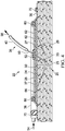
- a vacuum bag 36 which may be flexible, is placed over the rework patch 24 and sealed to the surface 38 of the structure 20 on the outer side 32 of the rework patch 24.
- the vacuum bag 36 is coupled with a suitable vacuum generator 45 and reservoir 44 which evacuates the vacuum bag 36 in order to compact the rework patch 24 prior to, during and/or after resin infusion.
- Resin infusion of the rework patch 24 may be carried out using a resin infusion system 35 comprising a controlled pressure resin reservoir 46, a removable vacuum source 42 and a controlled vacuum reservoir 44.
- Some components of the resin infusion system 35 may be similar to those shown in U.S. Patent No. 7,334,782 issued February 26, 2008 . The above mentioned U.S.
- Patent discloses a controlled atmospheric pressure resin infusion system (CAPRI) in which the resin reservoir 46 is evacuated to a pressure below atmospheric pressure and may be used in combination with cyclic (repeated) compaction by the vacuum bag 36 to control a vacuum assisted resin transfer process. It may be possible, however, to carry out the disclosed method using other types of resin infusion techniques and equipment. Moreover, the disclosed method may be carried out within an autoclave.
- CAPRI controlled atmospheric pressure resin infusion system
- the vacuum source 42 is placed beneath the thickest part of the rework patch 24, along the inner side of 33 of the repair patch 24, near the bottom 30 of the scarf cavity 26.
- the vacuum source 42 is coupled with the vacuum reservoir 44 by a vacuum line 40 that may pass through the vacuum bag 36. Resin from resin reservoir 46 is supplied through a resin supply tube 48 to the outer side 37 of the patch 24.
- the vacuum source 42 functions to reduce the pressure along the inner side 33 of the patch 24, at the bottom 30 of the scarf cavity 26, to a pressure level that is lower than the pressure within the vacuum bag 36 at the outer side 37 of the patch 24 produced by the vacuum generator 45.
- the pressure reduction created by the vacuum source 42 along the inner side 33 of the patch 24 results in a pressure differential between the inner and outer sides 33, 37 respectively of the patch 24, that forces resin to flow through the entire thickness of the rework patch 24.
- the vacuum source 42 also eliminates highpressure areas in the thickest part of the rework patch 24, near the inner side 33, which may otherwise result in air entrapment causing porosities. Excess resin flowing through the patch 24 to the inner side 33 of the patch 24 at the bottom 30 of the scarf cavity 26 is moved away through the vacuum line 40 into the vacuum reservoir 44. Following resin infusion of the rework patch 24, the vacuum source 42 is removed from the resin infused patch 24 and sealed before curing.
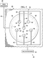
- FIGs 2 , 3 and 4 illustrate one practical embodiment of apparatus for reworking an area 26 of a structure 20.
- the structure 20 comprises a composite laminate skin 20, such as those used in the aircraft industry.
- the rework area 22 is scarfed ( Figures 2 and 4 ) only partially through the thickness of the skin 20, resulting in a scarf cavity 26 having tapered sides 27 (see Figure 3 ) and a generally flat bottom 30.
- a rework patch 24 comprising a dry fiber preform, is fabricated and placed within the scarf cavity 26, with the inner side 33 of the rework patch 24 in contact with the structure 20.
- the rework patch 24 may have tapered edges 29 ( Figure 4 ) substantially matching the tapered sides 27 of the scarf cavity 26.
- a release ply 66 is placed over the rework patch 24.
- the release ply 66 allows resin to flow therethrough and may comprise, without limitation, a porous Teflon® coated fiberglass.
- the scarf cavity 26 and the rework patch 24 are each substantially circular in shape.
- the disclosed method and apparatus may be used to rework areas 22 in which the scarf cavity 26 and the rework patch 24 are not circular, e.g. oval, square etc.
- One or more plies of a porous flow media 62 such as, without limitation, fiberglass, cover the release ply 66 and functions to distribute resin over the area of the rework patch 24.
- the flow media 62 may include a central, generally circular, or other shaped cutout 64 that functions to create a "dead zone" which aids in generating a desired wavefront of resin flow into the rework patch 24. In some applications, the cutout 64 may not be necessary where not required by the geometry of the patch 24.
- a circularly shaped, spiral wrap, resin distribution tube 60 which may be formed of a nylon or similar material, is disposed on top of the flow media 62, and extends around its periphery.
- the resin distribution tube 60 may have other geometries, depending upon the application, and is coupled with a resin supply tube 48.
- the resin supply tube 48 includes an inlet 54 that is coupled with the resin reservoir 46 ( Figure 1 ) which supplies resin under controlled pressure to the resin distribution tube 60.
- the vacuum bag 36 covers the rework patch 24 as well as the resin distribution tube 60, and is sealed to the outer surface 38 of the skin 20 by means of a suitable sealant 70, which may comprise a sealant tape.
- the vacuum source 42 previously discussed in connection with Figure 1 , comprises as a vacuum device a vacuum needle 50. A tip 25 on one end of the hollow needle 50 is open while the other end of the hollow needle 50 is coupled with the vacuum line 40.
- the hollow needle 50 penetrates 47 the vacuum bag 36 and passes through the central cutout 64 in the flow media 62, down into the repair patch 24, such that the open tip 25 of the hollow needle 50 is positioned substantially along the inner side 33 of the thickest part of the rework patch 24, at the bottom 30 of the scarf cavity 26.
- a suitable sealant 52 which may be similar to vacuum bag sealant 70, forms a substantially vacuum tight seal between the hollow needle 50 and the vacuum bag 36 at the point where the hollow needle 50 penetrates 47 ( Figure 4 ) the vacuum bag 36.
- resin infusion may be commenced and the vacuum bag 36 is evacuated to apply compaction pressure to the rework patch 24.
- Resin supplied under pressure from the resin reservoir 46 flows through the resin supply tube 48 and then into the resin distribution tube 60 where it flows onto and through the flow media 62.
- the flowing resin covers the flow media 62 which assists in evenly distributing the flowing resin over the upper surface of the rework patch 24.
- the vacuum reservoir 44 generates a vacuum in vacuum line 40 that results in the open tip 25 of the hollow needle 50 reducing the pressure at the thickest part of the rework patch 24, near the bottom 30 of the scarf cavity 26.
- the low pressure area at the open tip 25 is less than the pressure on the incoming resin. This reduced pressure at the open tip 25 causes any air or other volatiles in the rework patch 24 to be forced away, while the resin is forced down through the rework patch 24 to its thickest part.
- the pressure gradient assures that the rework patch 24 is fully infused with resin and that air does not become entrapped within the rework patch 24 during the resin infusion process. Excess resin, along with any air/volatiles present in the rework patch 24, are moved into the tip 25 and through the hollow needle 50 into the vacuum line 40 which carries the excess resin/air/volatiles to the vacuum reservoir 44.
- the rework patch 24 may be cyclically compacted by using the vacuum bag 36.
- air is introduced into the dry fiber preform and then evacuated in a cyclical manner, thereby further compacting the preform.
- the pressure in the resin reservoir 46 may be varied in relation to the pressure within the vacuum bag 36 in order to better control the net compaction pressure applied to the rework patch 24 as it is being infused with resin.
- the size of the open tip 25 of needle 50 may be chosen to allow free resin flow through the needle 50 enough to overcome the natural frictional forces on the walls of the needle 50 while minimizing the diameter of the penetration made in the vacuum bag 36.
- the rework patch 24 When the rework patch 24 is nearly fully impregnated with resin, excess resin will begin to flow through the hollow needle 50 into vacuum line 40 and is collected in the vacuum reservoir 44.
- the amount of vacuum pressure within the vacuum bag 36 may be adjusted so as to induce the flow of excess resin into the needle 50.
- the pressure within the vacuum reservoir 44 may also be adjusted so as to induce flow of excess resin through the hollow needle 50 and into the vacuum reservoir 44.
- the needle 50 may be withdrawn from the rework patch 24 and a hole (not shown) remaining in the vacuum bag 36 due to previous penetration by the needle 50 may be sealed using a suitable sealant, such as vacuum bag sealant, in order to maintain vacuum integrity of the bag 36 during curing.
- a relatively large area rework patch 24 is provided with multiple hollow needles 50 at spaced apart locations. Seals 52 seal each of the needles 50 to a vacuum bag 36 which covers the entire area of the rework patch 24.
- a series of resin exit lines 40 couple the hollow needles 50 with a vacuum reservoir 24 that reduces the internal pressure in the rework patch 24 at the locations of the needles 50. Resin is flowed into the rework patch 24 through a spiral wrap resin distribution tube 60 that is coupled with a resin reservoir 46 by a resin supply tube 48.
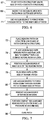
- FIG. 6 shows the overall steps of a method of reworking a structure 20 using a vacuum source 42 that is placed within the patch 24 and used to resin through the patch 24.
- a suitable patch 24 is placed on the structure 20, with the inner side 33 of the patch 24 in contact with the structure 20.
- a vacuum source 42 is inserted into the patch 24 from the outer side 37 of the patch 24.
- the vacuum source 42 is used to resin through the patch 24 to the inner side 33 of the patch 24.
- an adhesive ply, nominally 0.125-0.254 mm (0.005-0.010 inches) in thickness, or other means of enhancing the bondline 39 may be placed between the dry fiber patch 24 and the scarf cavity 26.
- Figure 7 illustrates the overall steps of another method of reworking an area of a structure 20 using a resin infused rework patch 24.
- a dry fiber rework patch 24 is placed on the structure 20, such that an inner side 33 of the patch 24 is in contact with the structure 20.
- an adhesive ply, nominally 0.125-0.254 mm (0.005-0.010 inches) in thickness, or other means of enhancing the bondline 39 may be placed between the dry fiber patch 24 and the scarf cavity 26.
- a vacuum bag 36 is placed over the rework patch 24 and is sealed to the structure 20. The vacuum bag 36 may be evacuated to compact the dry fiber rework patch 24 as desired, prior to its infusion with resin.
- a vacuum source 42 is positioned at the inner side 33 of the rework patch 24.
- resin is flowed onto the outer side 37 of the rework patch 24, and at 80, the vacuum source 42 is used to force resin down through the rework patch 24 to the inner side 33 of the rework patch 24 while reducing pressure on the inner side 33 of the patch 24.
- the vacuum source 42 is removed after infusion of the rework patch 24 with resin.
- the vacuum bag may 36 may maintain a desired level of compaction pressure on the rework patch 24 as it is being infused with resin during steps 78 and 80.
- the resin infused rework patch 24 may be further compacted by reducing the pressure within the vacuum bag 36.
- the resin infused patch 24 is cured.
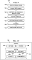
- Figure 8 illustrates the steps of a method of reworking a composite skin 20 according to the disclosed embodiments.
- a dry fiber preform rework patch 24 is prepared, as by tacking together layers of woven or knitted dry fabric.
- the skin 20 is prepared and cleaned in the area 22 to be reworked, and may be scarfed, as required, to remove inconsistencies and form a scarf cavity 26 into which the rework patch 24 may be placed.
- the rework patch 24 is installed in the scarf cavity 26.. If desired, an adhesive ply, nominally 0.125-0.254 mm (0.005-0.010 inches) in thickness, or other means of enhancing the bondline 39 may be placed between the dry fiber patch 24 and the scarf cavity 26.
- a finish ply (not shown) may be applied over the rework patch 24 at step 94.
- separation media such as a release ply 66 is installed, following which flow media 62 is installed at step 98.
- a resin supply tube which may comprise a spiral wrap resin distribution tube 60 is installed and connected with a resin reservoir 46.
- a vacuum bag 36 is installed in sealed over the rework patch 24.
- a hollow needle 50 is inserted through the vacuum bag 36 and through the thickest part of the rework patch 24, and the needle 50 is sealed to the vacuum bag 36.
- an open tip 25 of the needle 50 is positioned at the bottom of the scarf cavity, at a location where the rework patch 24 has a maximum thickness at the inner side 33 of the rework patch 24.
- a resin exit line 40 is connected between the hollow needle 50 and a vacuum reservoir 44.
- the vacuum bag 36 is evacuated at step 108 to begin compacting the rework patch 24.
- resin flow is commenced by flowing resin from the resin reservoir 46 through the resin distribution tube 60 onto the flow media 62.
- the flow of resin through the rework patch 24 is controlled by controlling the relative pressures of the resin reservoir 46 supplying resin to the rework patch 24, and the vacuum reservoir 44 used to locally reduce pressure at the thickest part of the rework patch 24 and move away excess resin.
- the hollow needle 50 is used to apply a vacuum at the bottom 30 of the scarf cavity 26 which both reduces pressure at the thickest part of the rework patch 24 and forces excess resin away from the rework patch 24 into the vacuum reservoir 44.
- the vacuum applied by the hollow needle 50 is lower than the pressure on the incoming resin, thus creating a pressure differential that drives the resin to flow to the bottom of the scarf cavity 26.
- the resin infusion process is completed, following which, at 118, the needle 50 is withdrawn from the rework patch 24 and a hole remaining in the vacuum bag due to previous penetration by the needle 50 is sealed.
- the rework patch 24 is cured at step 120, and at 122 the cured rework patch 24 may be trimmed, cleaned, sanded and smoothed, as necessary.
- Embodiments of the disclosure may find use in a variety of potential applications, particularly in the transportation industry, including for example, aerospace, marine, automotive applications and other application where automated layup equipment may be used.
- embodiments of the disclosure may be used in the context of an aircraft manufacturing and service method 124 as shown in Figure 9 and an aircraft 126 as shown in Figure 10 .
- Aircraft applications of the disclosed embodiments may include, for example, without limitation, composite skins and other load carrying structures.
- exemplary method 124 may include specification and design 128 of the aircraft 126 and material procurement 130.
- component and subassembly manufacturing 132 and system integration 134 of the aircraft 126 takes place.
- the aircraft 126 may go through certification and delivery 136 in order to be placed in service 138. While in service by a customer, the aircraft 126 is scheduled for routine maintenance and service 140, which may also include modification, reconfiguration, refurbishment, and so on.
- routine maintenance and service 140 which may also include modification, reconfiguration, refurbishment, and so on.
- the disclosed method may be employed to rework, repair or reinforce structural areas of the aircraft 126 while in service.
- Each of the processes of method 124 may be performed or carried out by a system integrator, a third party, and/or an operator (e.g., a customer).
- a system integrator may include without limitation any number of aircraft manufacturers and major-system subcontractors
- a third party may include without limitation any number of vendors, subcontractors, and suppliers
- an operator may be an airline, leasing company, military entity, service organization, and so on.
- the aircraft 126 produced by exemplary method 124 may include an airframe 142 with a plurality of systems 144 and an interior 146.
- high-level systems 144 include one or more of a propulsion system 148, an electrical system 150, a hydraulic system 12 to, and an environmental system 154. Any number of other systems may be included.
- an aerospace example is shown, the principles of the disclosure may be applied to other industries, such as the marine and automotive industries.
- Systems and methods embodied herein may be employed during any one or more of the stages of the production and service method 124. For example, components or subassemblies corresponding to production process 128 may be reworked while the aircraft 126 is in service. Also, one or more apparatus embodiments, method embodiments, or a combination thereof may be utilized during the production stages 132 and 134, for example, by substantially expediting assembly of or reducing the maintenance cost of an aircraft 126. Similarly, one or more of apparatus embodiments, method embodiments, or a combination thereof may be utilized while the aircraft 126 is in service, for example and without limitation, to maintenance and service 140.
Landscapes
- Engineering & Computer Science (AREA)
- Mechanical Engineering (AREA)
- Chemical & Material Sciences (AREA)
- Composite Materials (AREA)
- Casting Or Compression Moulding Of Plastics Or The Like (AREA)
- Moulding By Coating Moulds (AREA)
- Reinforced Plastic Materials (AREA)
Claims (10)
- Verfahren zum Nacharbeiten eines Bereichs (22) einer Verbundstruktur (20), das aufweist:Platzieren eines trockenen Faserflickens (24) auf der Struktur (20);Platzieren eines Vakuumsbeutels (36) über eine äußere Seite (37) des Flickens (24);Einführen einer Vakuumquelle (42) in den Flicken (24) von der äußeren Seite (37) des Flickens (24), wobei ein Einführen der Vakuumquelle (42) ferner ein Einführen einer hohlen Nadel (50) durch den Vakuumsbeutel (36) umfasst, und Ausbilden einer im Wesentlichen vakuumdichten Dichtung (52) zwischen der hohlen Nadel (50) und dem Vakuumsbeutel (36);
Füllen des Flickens (24) mit Harz durch Einströmen von Harz in den Flicken (24) von der äußeren Seite (37) davon; undVerwenden der hohlen Nadel (50) als die Vakuumquelle (42), um Harz durch den Flicken (24) zu einer inneren Seite (33) des Flickens (24) zu treiben. - Verfahren nach Anspruch 1, wobei ein Platzieren eines Flickens (24) auf der Struktur (20) umfasst:Platzieren des trockenen Faserflickens (24) auf der Struktur (20), undPlatzieren einer bindungsverbessernden Schicht zwischen dem trockenen Faserflicken (24) und der Struktur (20).
- Verfahren nach Anspruch 1 oder 2, das des Weiteren aufweist:Entfernen der Vakuumquelle (42) vom Flicken (24), nachdem der Flicken (24) mit Harz gefüllt wurde.
- Verfahren nach einem der vorhergehenden Ansprüche, das des Weiteren aufweist:Bilden einer Verlaschung (26) teilweise durch eine Dicke (t) der Struktur (20), undwobei ein Platzieren des Faserflickens (24) auf der Struktur (20) ein Platzieren der inneren Seite (33) des Flickens (24) gegen einen Boden (30) der Verlaschung (26) umfasst, und wobei ein Einführen der Vakuumquelle (42) ein Einführen der hohlen Nadel (50) hinunter durch den dicken Teil des Flickens (24) bis im Wesentlichen zum Boden (30) der Verlaschung (26) umfasst.
- Verfahren nach Anspruch 3, wobei ein Entfernen der Vakuumquelle (42) aus dem Flicken (24) umfasst:Zurückziehen der hohlen Nadel (50) aus dem Flicken (24) und aus dem Vakuumbeutel (36), undAbdichten eines Lochs in dem Vakuumbeutel (36), der aus einer Penetration des Vakuumbeutels (36) während einer Einführung der hohlen Nadel (50) durch den Vakuumbeutel (36) resultiert.
- Verfahren nach einem der vorhergehenden Ansprüche, wobei ein Einführen einer Vakuumquelle (42) in den Flicken (24) umfasst:Einführen einer Vielzahl von hohlen Nadeln (50) durch den Flicken (24) bei voneinander beabstandeten Orten über einen Bereich des Flickens (24).
- Verfahren nach einem der vorhergehenden Ansprüche, das des Weiteren aufweist:Füllen des Flickens (24) mit Harz unter Verwendung eines Differentialharzdrucks.
- Verfahren nach einem der vorhergehenden Ansprüche, wobei ein Einströmen von Harz in den Flicken (24) von der äußeren Seite (37) davon umfasst:Platzieren eines Harzverteilrohrs (60) an der äußeren Seite (37) des Flickens (24) unter dem Vakuumbeutel (36), undZuführen von Harz in das Harzverteilrohr (60).
- Vorrichtung zum Nacharbeiten eines Bereichs (22) einer Verbundstruktur (20) unter Verwendung einer Harzinfusion eines trockenen Faserflickens (24), der eine innere Seite (33) und eine äußere Seite (37) aufweist, die aufweist:einen Vakuumbeutel (36), der angepasst ist, über der äußeren Seite (37) des Faserflickens (24) zum Verdichten des Faserflickens (24) platziert zu werden; dadurch gekennzeichnet, dass die Vorrichtung des Weiteren aufweist:eine hohle Nadel (50), die durch den Vakuumbeutel (36) verläuft und die angepasst ist, sich durch eine Dicke (d) des Faserflickens (24) nach unten zu erstrecken;eine Vakuumdichtung (52) zwischen der hohlen Nadel (50) und dem Vakuumbeutel (36); undeine Vakuumleitung (40), die mit der hohlen Nadel (50) zum Erzeugen eines Vakuums bei der inneren Seite (33) des Faserflickens (24) gekoppelt ist.
- Vorrichtung nach Anspruch 9, die des Weiteren aufweist:ein Harzreservoir (46) zum Zuführen von Harz zur äußeren Seite (37) des Faserflickens (24) unter einem kontrollierten Partialatmosphärendruck; undeine Vakuumquelle, die mit der hohlen Nadel (50) zum Erzeugen eines Vakuums auf der inneren Seite (33) des Faserflickens (24) und zum Treiben eines überschüssigen Harzes aus dem Faserflicken (24) heraus gekoppelt ist.
Applications Claiming Priority (2)
| Application Number | Priority Date | Filing Date | Title |
|---|---|---|---|
| US13/761,785 US9579873B2 (en) | 2013-02-07 | 2013-02-07 | Method and apparatus for reworking structures |
| PCT/US2014/010290 WO2014123646A1 (en) | 2013-02-07 | 2014-01-06 | Method and apparatus for reworking structures |
Publications (2)
| Publication Number | Publication Date |
|---|---|
| EP2953786A1 EP2953786A1 (de) | 2015-12-16 |
| EP2953786B1 true EP2953786B1 (de) | 2018-04-18 |
Family
ID=50031549
Family Applications (1)
| Application Number | Title | Priority Date | Filing Date |
|---|---|---|---|
| EP14702330.3A Active EP2953786B1 (de) | 2013-02-07 | 2014-01-06 | Verfahren und vorrichtung zur überarbeitung von strukturen |
Country Status (11)
| Country | Link |
|---|---|
| US (1) | US9579873B2 (de) |
| EP (1) | EP2953786B1 (de) |
| JP (1) | JP6452628B2 (de) |
| KR (1) | KR101988470B1 (de) |
| CN (1) | CN104918774B (de) |
| BR (1) | BR112015017742B1 (de) |
| CA (1) | CA2898023C (de) |
| ES (1) | ES2678097T3 (de) |
| PT (1) | PT2953786T (de) |
| TR (1) | TR201807804T4 (de) |
| WO (1) | WO2014123646A1 (de) |
Families Citing this family (12)
| Publication number | Priority date | Publication date | Assignee | Title |
|---|---|---|---|---|
| GB2531600A (en) * | 2014-10-24 | 2016-04-27 | Short Brothers Plc | Apparatus and methods for manufacturing and repairing fibre-reinforced composite materials |
| FR3048634B1 (fr) * | 2016-03-11 | 2018-04-06 | Safran Aircraft Engines | Dispositif et procede de moulage par injection d'un polymere liquide |
| WO2017165475A1 (en) * | 2016-03-25 | 2017-09-28 | Short Brothers Plc | Apparatus and methods for repairing composite laminates |
| US10946594B1 (en) * | 2017-01-06 | 2021-03-16 | Cornerstone Research Group, Inc. | Reinforced polymer-infused fiber composite repair system and methods for repairing composite materials |
| EP3450150B1 (de) | 2017-09-04 | 2019-11-13 | Grupo Navec Servicios Industriales, SL | In-situ-wiederaufbauverfahren für in-situ-wiederaufbau und reparatur von rohren und behälterstrukturen |
| US10814533B2 (en) * | 2017-11-30 | 2020-10-27 | The Boeing Company | Systems and methods for applying vacuum pressure to composite parts |
| US11110668B2 (en) * | 2018-06-26 | 2021-09-07 | The Boeing Company | Apparatus and method for facilitating a vacuum bagging operation during fabrication of a composite laminate |
| US11548102B2 (en) * | 2020-07-31 | 2023-01-10 | General Electric Company | Method for repairing composite components using a plug |
| US20220184900A1 (en) * | 2020-12-11 | 2022-06-16 | Remarkable Foods, Inc. | Method and Apparatus For Forming a Composite Object |
| EP4019231B1 (de) * | 2020-12-17 | 2024-01-03 | The Boeing Company | Systeme und verfahren zur klebstoffinjizierten flickenreparatur |
| US11865656B2 (en) * | 2021-06-17 | 2024-01-09 | The Boeing Company | In situ crack repair in structures |
| CN113877865B (zh) * | 2021-11-10 | 2022-12-09 | 段瑞 | 一种农业大棚膜内部清洗器 |
Family Cites Families (19)
| Publication number | Priority date | Publication date | Assignee | Title |
|---|---|---|---|---|
| FR89458E (fr) | 1965-05-31 | 1967-06-30 | Procédé de construction en matéraiux légers, de corps de toutes natures, tels que toitures ou murs d'édifices, citernes ou encore coques de bateaux | |
| JPS5862017A (ja) * | 1981-10-09 | 1983-04-13 | Hitachi Zosen Corp | 繊維強化樹脂品の成形方法 |
| US5699838A (en) | 1995-05-22 | 1997-12-23 | Inliner, U.S.A. | Apparatus for vacuum impregnation of a flexible, hollow tube |
| US6555045B2 (en) * | 1999-01-11 | 2003-04-29 | Northrop Grumman Corporation | Grooved mold apparatus and process for forming fiber reinforced composite structures |
| DE60018455T3 (de) | 1999-12-07 | 2009-02-19 | The Boeing Company, Seattle | Doppelfolien vakuuminjektionsverfahren zur herstellung eines verbundwerkstoffes und damit hergestellter verbundwerkstoff |
| US6385836B1 (en) * | 2000-06-30 | 2002-05-14 | Lockheed Martin Corporation | Method for composite material repair |
| US6586054B2 (en) | 2001-04-24 | 2003-07-01 | The United States Of America As Represented By The Secretary Of The Army | Apparatus and method for selectively distributing and controlling a means for impregnation of fibrous articles |
| US7138028B2 (en) | 2001-07-26 | 2006-11-21 | The Boeing Company | Vacuum assisted resin transfer method for co-bonding composite laminate structures |
| US20030019567A1 (en) | 2001-07-26 | 2003-01-30 | Burpo Steven J. | Vacuum assisted resin transfer method for co-bonding composite laminate structures |
| CA2484174C (en) | 2002-05-29 | 2008-12-02 | The Boeing Company | Controlled atmospheric pressure resin infusion process |
| JP4220874B2 (ja) * | 2002-12-11 | 2009-02-04 | 三菱重工業株式会社 | 樹脂含浸センサ・補修器及び樹脂含浸補修器並びに補修方法 |
| US6896841B2 (en) | 2003-03-20 | 2005-05-24 | The Boeing Company | Molding process and apparatus for producing unified composite structures |
| DK176135B1 (da) * | 2004-11-30 | 2006-09-18 | Lm Glasfiber As | Vakuuminfusion ved hjælp af semipermeabel membran |
| US7633040B2 (en) | 2005-11-14 | 2009-12-15 | The Boeing Company | Bulk resin infusion system apparatus and method |
| US20080136060A1 (en) * | 2006-12-08 | 2008-06-12 | Gkn Westland Aerospace, Inc. | System and method for forming and curing a composite structure |
| DK2222454T3 (da) * | 2007-12-21 | 2014-01-27 | Vestas Wind Sys As | Fremgangsmåde til reparation af en fast fiberkompositdel |
| US20090309260A1 (en) | 2008-06-12 | 2009-12-17 | Kenneth Herbert Keuchel | Method of delivering a thermoplastic and/or crosslinking resin to a composite laminate structure |
| WO2012154544A2 (en) | 2011-05-06 | 2012-11-15 | Purdue Research Foundation | Method and system of vacuum assisted resin transfer molding for repair of composite materials and structure |
| US8945321B2 (en) | 2011-05-30 | 2015-02-03 | The Boeing Company | Method and apparatus for reworking structures using resin infusion of fiber preforms |
-
2013
- 2013-02-07 US US13/761,785 patent/US9579873B2/en active Active
-
2014
- 2014-01-06 CA CA2898023A patent/CA2898023C/en active Active
- 2014-01-06 WO PCT/US2014/010290 patent/WO2014123646A1/en active Application Filing
- 2014-01-06 BR BR112015017742-5A patent/BR112015017742B1/pt active IP Right Grant
- 2014-01-06 ES ES14702330.3T patent/ES2678097T3/es active Active
- 2014-01-06 TR TR2018/07804T patent/TR201807804T4/tr unknown
- 2014-01-06 EP EP14702330.3A patent/EP2953786B1/de active Active
- 2014-01-06 PT PT147023303T patent/PT2953786T/pt unknown
- 2014-01-06 JP JP2015556943A patent/JP6452628B2/ja active Active
- 2014-01-06 CN CN201480004886.5A patent/CN104918774B/zh active Active
- 2014-01-06 KR KR1020157021566A patent/KR101988470B1/ko active IP Right Grant
Non-Patent Citations (1)
| Title |
|---|
| None * |
Also Published As
| Publication number | Publication date |
|---|---|
| CA2898023A1 (en) | 2014-08-14 |
| BR112015017742B1 (pt) | 2020-11-10 |
| CN104918774B (zh) | 2017-04-05 |
| ES2678097T3 (es) | 2018-08-08 |
| EP2953786A1 (de) | 2015-12-16 |
| TR201807804T4 (tr) | 2018-06-21 |
| US9579873B2 (en) | 2017-02-28 |
| CN104918774A (zh) | 2015-09-16 |
| PT2953786T (pt) | 2018-07-04 |
| KR20150115795A (ko) | 2015-10-14 |
| CA2898023C (en) | 2018-10-16 |
| KR101988470B1 (ko) | 2019-06-12 |
| JP2016506885A (ja) | 2016-03-07 |
| BR112015017742A2 (pt) | 2017-07-11 |
| WO2014123646A1 (en) | 2014-08-14 |
| JP6452628B2 (ja) | 2019-01-16 |
| US20140216634A1 (en) | 2014-08-07 |
Similar Documents
| Publication | Publication Date | Title |
|---|---|---|
| EP2953786B1 (de) | Verfahren und vorrichtung zur überarbeitung von strukturen | |
| EP2529921B1 (de) | Verfahren und Vorrichtung zur Neuerarbeitung von Strukturen unter Verwendung von Harzinfusionen aus Faservorformen | |
| AU2020201610B2 (en) | Fabrication of composite laminates using temporarily stitched preforms | |
| US9090028B2 (en) | Method for producing contoured composite structures and structures produced thereby | |
| EP2331612B1 (de) | Faltenminimierung bei ungehärteten verbundlaminaten | |
| US8298473B2 (en) | Method of making a cure tool with integrated edge breather | |
| EP2599615B1 (de) | Verringerung der Porosität in Verbundstoffstrukturen | |
| JP2013527894A (ja) | 統合エンジンナセル構造 | |
| RU2747007C2 (ru) | Способ локального влияния на проницаемость для смолы сухой заготовки | |
| AU2019201057B2 (en) | Caul plates that define channels for distributing resin to composite parts |
Legal Events
| Date | Code | Title | Description |
|---|---|---|---|
| PUAI | Public reference made under article 153(3) epc to a published international application that has entered the european phase |
Free format text: ORIGINAL CODE: 0009012 |
|
| 17P | Request for examination filed |
Effective date: 20150819 |
|
| AK | Designated contracting states |
Kind code of ref document: A1 Designated state(s): AL AT BE BG CH CY CZ DE DK EE ES FI FR GB GR HR HU IE IS IT LI LT LU LV MC MK MT NL NO PL PT RO RS SE SI SK SM TR |
|
| AX | Request for extension of the european patent |
Extension state: BA ME |
|
| DAX | Request for extension of the european patent (deleted) | ||
| GRAP | Despatch of communication of intention to grant a patent |
Free format text: ORIGINAL CODE: EPIDOSNIGR1 |
|
| STAA | Information on the status of an ep patent application or granted ep patent |
Free format text: STATUS: GRANT OF PATENT IS INTENDED |
|
| INTG | Intention to grant announced |
Effective date: 20170828 |
|
| GRAJ | Information related to disapproval of communication of intention to grant by the applicant or resumption of examination proceedings by the epo deleted |
Free format text: ORIGINAL CODE: EPIDOSDIGR1 |
|
| STAA | Information on the status of an ep patent application or granted ep patent |
Free format text: STATUS: REQUEST FOR EXAMINATION WAS MADE |
|
| GRAP | Despatch of communication of intention to grant a patent |
Free format text: ORIGINAL CODE: EPIDOSNIGR1 |
|
| INTC | Intention to grant announced (deleted) | ||
| STAA | Information on the status of an ep patent application or granted ep patent |
Free format text: STATUS: GRANT OF PATENT IS INTENDED |
|
| GRAS | Grant fee paid |
Free format text: ORIGINAL CODE: EPIDOSNIGR3 |
|
| INTG | Intention to grant announced |
Effective date: 20180215 |
|
| GRAA | (expected) grant |
Free format text: ORIGINAL CODE: 0009210 |
|
| STAA | Information on the status of an ep patent application or granted ep patent |
Free format text: STATUS: THE PATENT HAS BEEN GRANTED |
|
| AK | Designated contracting states |
Kind code of ref document: B1 Designated state(s): AL AT BE BG CH CY CZ DE DK EE ES FI FR GB GR HR HU IE IS IT LI LT LU LV MC MK MT NL NO PL PT RO RS SE SI SK SM TR |
|
| REG | Reference to a national code |
Ref country code: GB Ref legal event code: FG4D |
|
| REG | Reference to a national code |
Ref country code: CH Ref legal event code: EP |
|
| REG | Reference to a national code |
Ref country code: AT Ref legal event code: REF Ref document number: 989967 Country of ref document: AT Kind code of ref document: T Effective date: 20180515 |
|
| REG | Reference to a national code |
Ref country code: IE Ref legal event code: FG4D |
|
| REG | Reference to a national code |
Ref country code: DE Ref legal event code: R096 Ref document number: 602014024051 Country of ref document: DE |
|
| REG | Reference to a national code |
Ref country code: PT Ref legal event code: SC4A Ref document number: 2953786 Country of ref document: PT Date of ref document: 20180704 Kind code of ref document: T Free format text: AVAILABILITY OF NATIONAL TRANSLATION Effective date: 20180628 |
|
| REG | Reference to a national code |
Ref country code: SE Ref legal event code: TRGR |
|
| REG | Reference to a national code |
Ref country code: ES Ref legal event code: FG2A Ref document number: 2678097 Country of ref document: ES Kind code of ref document: T3 Effective date: 20180808 |
|
| REG | Reference to a national code |
Ref country code: NL Ref legal event code: MP Effective date: 20180418 |
|
| REG | Reference to a national code |
Ref country code: LT Ref legal event code: MG4D |
|
| PG25 | Lapsed in a contracting state [announced via postgrant information from national office to epo] |
Ref country code: NL Free format text: LAPSE BECAUSE OF FAILURE TO SUBMIT A TRANSLATION OF THE DESCRIPTION OR TO PAY THE FEE WITHIN THE PRESCRIBED TIME-LIMIT Effective date: 20180418 |
|
| PG25 | Lapsed in a contracting state [announced via postgrant information from national office to epo] |
Ref country code: PL Free format text: LAPSE BECAUSE OF FAILURE TO SUBMIT A TRANSLATION OF THE DESCRIPTION OR TO PAY THE FEE WITHIN THE PRESCRIBED TIME-LIMIT Effective date: 20180418 Ref country code: LT Free format text: LAPSE BECAUSE OF FAILURE TO SUBMIT A TRANSLATION OF THE DESCRIPTION OR TO PAY THE FEE WITHIN THE PRESCRIBED TIME-LIMIT Effective date: 20180418 Ref country code: AL Free format text: LAPSE BECAUSE OF FAILURE TO SUBMIT A TRANSLATION OF THE DESCRIPTION OR TO PAY THE FEE WITHIN THE PRESCRIBED TIME-LIMIT Effective date: 20180418 Ref country code: NO Free format text: LAPSE BECAUSE OF FAILURE TO SUBMIT A TRANSLATION OF THE DESCRIPTION OR TO PAY THE FEE WITHIN THE PRESCRIBED TIME-LIMIT Effective date: 20180718 Ref country code: BG Free format text: LAPSE BECAUSE OF FAILURE TO SUBMIT A TRANSLATION OF THE DESCRIPTION OR TO PAY THE FEE WITHIN THE PRESCRIBED TIME-LIMIT Effective date: 20180718 Ref country code: FI Free format text: LAPSE BECAUSE OF FAILURE TO SUBMIT A TRANSLATION OF THE DESCRIPTION OR TO PAY THE FEE WITHIN THE PRESCRIBED TIME-LIMIT Effective date: 20180418 |
|
| PG25 | Lapsed in a contracting state [announced via postgrant information from national office to epo] |
Ref country code: HR Free format text: LAPSE BECAUSE OF FAILURE TO SUBMIT A TRANSLATION OF THE DESCRIPTION OR TO PAY THE FEE WITHIN THE PRESCRIBED TIME-LIMIT Effective date: 20180418 Ref country code: RS Free format text: LAPSE BECAUSE OF FAILURE TO SUBMIT A TRANSLATION OF THE DESCRIPTION OR TO PAY THE FEE WITHIN THE PRESCRIBED TIME-LIMIT Effective date: 20180418 Ref country code: LV Free format text: LAPSE BECAUSE OF FAILURE TO SUBMIT A TRANSLATION OF THE DESCRIPTION OR TO PAY THE FEE WITHIN THE PRESCRIBED TIME-LIMIT Effective date: 20180418 Ref country code: GR Free format text: LAPSE BECAUSE OF FAILURE TO SUBMIT A TRANSLATION OF THE DESCRIPTION OR TO PAY THE FEE WITHIN THE PRESCRIBED TIME-LIMIT Effective date: 20180719 |
|
| REG | Reference to a national code |
Ref country code: AT Ref legal event code: MK05 Ref document number: 989967 Country of ref document: AT Kind code of ref document: T Effective date: 20180418 |
|
| REG | Reference to a national code |
Ref country code: DE Ref legal event code: R097 Ref document number: 602014024051 Country of ref document: DE |
|
| PG25 | Lapsed in a contracting state [announced via postgrant information from national office to epo] |
Ref country code: SK Free format text: LAPSE BECAUSE OF FAILURE TO SUBMIT A TRANSLATION OF THE DESCRIPTION OR TO PAY THE FEE WITHIN THE PRESCRIBED TIME-LIMIT Effective date: 20180418 Ref country code: CZ Free format text: LAPSE BECAUSE OF FAILURE TO SUBMIT A TRANSLATION OF THE DESCRIPTION OR TO PAY THE FEE WITHIN THE PRESCRIBED TIME-LIMIT Effective date: 20180418 Ref country code: AT Free format text: LAPSE BECAUSE OF FAILURE TO SUBMIT A TRANSLATION OF THE DESCRIPTION OR TO PAY THE FEE WITHIN THE PRESCRIBED TIME-LIMIT Effective date: 20180418 Ref country code: DK Free format text: LAPSE BECAUSE OF FAILURE TO SUBMIT A TRANSLATION OF THE DESCRIPTION OR TO PAY THE FEE WITHIN THE PRESCRIBED TIME-LIMIT Effective date: 20180418 Ref country code: RO Free format text: LAPSE BECAUSE OF FAILURE TO SUBMIT A TRANSLATION OF THE DESCRIPTION OR TO PAY THE FEE WITHIN THE PRESCRIBED TIME-LIMIT Effective date: 20180418 Ref country code: EE Free format text: LAPSE BECAUSE OF FAILURE TO SUBMIT A TRANSLATION OF THE DESCRIPTION OR TO PAY THE FEE WITHIN THE PRESCRIBED TIME-LIMIT Effective date: 20180418 |
|
| PLBE | No opposition filed within time limit |
Free format text: ORIGINAL CODE: 0009261 |
|
| STAA | Information on the status of an ep patent application or granted ep patent |
Free format text: STATUS: NO OPPOSITION FILED WITHIN TIME LIMIT |
|
| PG25 | Lapsed in a contracting state [announced via postgrant information from national office to epo] |
Ref country code: SM Free format text: LAPSE BECAUSE OF FAILURE TO SUBMIT A TRANSLATION OF THE DESCRIPTION OR TO PAY THE FEE WITHIN THE PRESCRIBED TIME-LIMIT Effective date: 20180418 |
|
| 26N | No opposition filed |
Effective date: 20190121 |
|
| PG25 | Lapsed in a contracting state [announced via postgrant information from national office to epo] |
Ref country code: SI Free format text: LAPSE BECAUSE OF FAILURE TO SUBMIT A TRANSLATION OF THE DESCRIPTION OR TO PAY THE FEE WITHIN THE PRESCRIBED TIME-LIMIT Effective date: 20180418 |
|
| PG25 | Lapsed in a contracting state [announced via postgrant information from national office to epo] |
Ref country code: MC Free format text: LAPSE BECAUSE OF FAILURE TO SUBMIT A TRANSLATION OF THE DESCRIPTION OR TO PAY THE FEE WITHIN THE PRESCRIBED TIME-LIMIT Effective date: 20180418 |
|
| REG | Reference to a national code |
Ref country code: CH Ref legal event code: PL |
|
| PG25 | Lapsed in a contracting state [announced via postgrant information from national office to epo] |
Ref country code: LU Free format text: LAPSE BECAUSE OF NON-PAYMENT OF DUE FEES Effective date: 20190106 |
|
| REG | Reference to a national code |
Ref country code: BE Ref legal event code: MM Effective date: 20190131 |
|
| REG | Reference to a national code |
Ref country code: IE Ref legal event code: MM4A |
|
| PG25 | Lapsed in a contracting state [announced via postgrant information from national office to epo] |
Ref country code: BE Free format text: LAPSE BECAUSE OF NON-PAYMENT OF DUE FEES Effective date: 20190131 |
|
| PG25 | Lapsed in a contracting state [announced via postgrant information from national office to epo] |
Ref country code: CH Free format text: LAPSE BECAUSE OF NON-PAYMENT OF DUE FEES Effective date: 20190131 Ref country code: LI Free format text: LAPSE BECAUSE OF NON-PAYMENT OF DUE FEES Effective date: 20190131 |
|
| PG25 | Lapsed in a contracting state [announced via postgrant information from national office to epo] |
Ref country code: IE Free format text: LAPSE BECAUSE OF NON-PAYMENT OF DUE FEES Effective date: 20190106 |
|
| PG25 | Lapsed in a contracting state [announced via postgrant information from national office to epo] |
Ref country code: MT Free format text: LAPSE BECAUSE OF NON-PAYMENT OF DUE FEES Effective date: 20190106 |
|
| PG25 | Lapsed in a contracting state [announced via postgrant information from national office to epo] |
Ref country code: CY Free format text: LAPSE BECAUSE OF FAILURE TO SUBMIT A TRANSLATION OF THE DESCRIPTION OR TO PAY THE FEE WITHIN THE PRESCRIBED TIME-LIMIT Effective date: 20180418 |
|
| PG25 | Lapsed in a contracting state [announced via postgrant information from national office to epo] |
Ref country code: IS Free format text: LAPSE BECAUSE OF FAILURE TO SUBMIT A TRANSLATION OF THE DESCRIPTION OR TO PAY THE FEE WITHIN THE PRESCRIBED TIME-LIMIT Effective date: 20180818 |
|
| PG25 | Lapsed in a contracting state [announced via postgrant information from national office to epo] |
Ref country code: HU Free format text: LAPSE BECAUSE OF FAILURE TO SUBMIT A TRANSLATION OF THE DESCRIPTION OR TO PAY THE FEE WITHIN THE PRESCRIBED TIME-LIMIT; INVALID AB INITIO Effective date: 20140106 |
|
| PG25 | Lapsed in a contracting state [announced via postgrant information from national office to epo] |
Ref country code: MK Free format text: LAPSE BECAUSE OF FAILURE TO SUBMIT A TRANSLATION OF THE DESCRIPTION OR TO PAY THE FEE WITHIN THE PRESCRIBED TIME-LIMIT Effective date: 20180418 |
|
| PGFP | Annual fee paid to national office [announced via postgrant information from national office to epo] |
Ref country code: FR Payment date: 20230125 Year of fee payment: 10 |
|
| PGFP | Annual fee paid to national office [announced via postgrant information from national office to epo] |
Ref country code: TR Payment date: 20230106 Year of fee payment: 10 Ref country code: SE Payment date: 20230127 Year of fee payment: 10 Ref country code: IT Payment date: 20230120 Year of fee payment: 10 |
|
| P01 | Opt-out of the competence of the unified patent court (upc) registered |
Effective date: 20230516 |
|
| PGFP | Annual fee paid to national office [announced via postgrant information from national office to epo] |
Ref country code: PT Payment date: 20231219 Year of fee payment: 11 |
|
| PGFP | Annual fee paid to national office [announced via postgrant information from national office to epo] |
Ref country code: ES Payment date: 20240201 Year of fee payment: 11 |
|
| PGFP | Annual fee paid to national office [announced via postgrant information from national office to epo] |
Ref country code: DE Payment date: 20240129 Year of fee payment: 11 Ref country code: GB Payment date: 20240129 Year of fee payment: 11 |