EP2953447B1 - Pflanzenwachstumssystem - Google Patents
Pflanzenwachstumssystem Download PDFInfo
- Publication number
- EP2953447B1 EP2953447B1 EP14703823.6A EP14703823A EP2953447B1 EP 2953447 B1 EP2953447 B1 EP 2953447B1 EP 14703823 A EP14703823 A EP 14703823A EP 2953447 B1 EP2953447 B1 EP 2953447B1
- Authority
- EP
- European Patent Office
- Prior art keywords
- plant growth
- slab
- water
- block
- plant
- Prior art date
- Legal status (The legal status is an assumption and is not a legal conclusion. Google has not performed a legal analysis and makes no representation as to the accuracy of the status listed.)
- Active
Links
Images


Classifications
-
- A—HUMAN NECESSITIES
- A01—AGRICULTURE; FORESTRY; ANIMAL HUSBANDRY; HUNTING; TRAPPING; FISHING
- A01G—HORTICULTURE; CULTIVATION OF VEGETABLES, FLOWERS, RICE, FRUIT, VINES, HOPS OR SEAWEED; FORESTRY; WATERING
- A01G31/00—Soilless cultivation, e.g. hydroponics
- A01G31/02—Special apparatus therefor
-
- A—HUMAN NECESSITIES
- A01—AGRICULTURE; FORESTRY; ANIMAL HUSBANDRY; HUNTING; TRAPPING; FISHING
- A01G—HORTICULTURE; CULTIVATION OF VEGETABLES, FLOWERS, RICE, FRUIT, VINES, HOPS OR SEAWEED; FORESTRY; WATERING
- A01G25/00—Watering gardens, fields, sports grounds or the like
- A01G25/16—Control of watering
-
- A—HUMAN NECESSITIES
- A01—AGRICULTURE; FORESTRY; ANIMAL HUSBANDRY; HUNTING; TRAPPING; FISHING
- A01G—HORTICULTURE; CULTIVATION OF VEGETABLES, FLOWERS, RICE, FRUIT, VINES, HOPS OR SEAWEED; FORESTRY; WATERING
- A01G7/00—Botany in general
-
- A—HUMAN NECESSITIES
- A01—AGRICULTURE; FORESTRY; ANIMAL HUSBANDRY; HUNTING; TRAPPING; FISHING
- A01G—HORTICULTURE; CULTIVATION OF VEGETABLES, FLOWERS, RICE, FRUIT, VINES, HOPS OR SEAWEED; FORESTRY; WATERING
- A01G24/00—Growth substrates; Culture media; Apparatus or methods therefor
- A01G24/10—Growth substrates; Culture media; Apparatus or methods therefor based on or containing inorganic material
- A01G24/18—Growth substrates; Culture media; Apparatus or methods therefor based on or containing inorganic material containing inorganic fibres, e.g. mineral wool
-
- Y—GENERAL TAGGING OF NEW TECHNOLOGICAL DEVELOPMENTS; GENERAL TAGGING OF CROSS-SECTIONAL TECHNOLOGIES SPANNING OVER SEVERAL SECTIONS OF THE IPC; TECHNICAL SUBJECTS COVERED BY FORMER USPC CROSS-REFERENCE ART COLLECTIONS [XRACs] AND DIGESTS
- Y02—TECHNOLOGIES OR APPLICATIONS FOR MITIGATION OR ADAPTATION AGAINST CLIMATE CHANGE
- Y02P—CLIMATE CHANGE MITIGATION TECHNOLOGIES IN THE PRODUCTION OR PROCESSING OF GOODS
- Y02P60/00—Technologies relating to agriculture, livestock or agroalimentary industries
- Y02P60/20—Reduction of greenhouse gas [GHG] emissions in agriculture, e.g. CO2
- Y02P60/21—Dinitrogen oxide [N2O], e.g. using aquaponics, hydroponics or efficiency measures
Definitions
- the present invention relates to the growth of plants in artificial substrates.
- the present invention relates to the growth of plants in mineral wool substrates.
- Such growth substrates are typically provided as a coherent plug, block, slab or mat/blanket and generally include a binder, usually an organic binder, in order to provide structural integrity to the product.
- the growth process of the plant is managed in two stages: a first stage managed by a "propagator” in which the plant is grown from seed; and a second stage managed by a “grower” during which the plant is sustained and any harvest taken.
- the propagator may plant individual tomato seeds in cylindrical plugs having a thickness in the order of 25-30mm and a radius of around 20-30mm. After germination of the seed, the propagator places the plug within a cuboid block to allow further growth of the root system and the plant. The individual plant within the block is then nursed until a stage when it can be transferred from the propagator to the grower.
- a single plant in a block is split into two by splitting a stem during an early phase of growth, resulting in two plants sharing a single root system.
- multiple plants may be grafted together and grown within a single block.
- the grower places a number of blocks on a single slab of mineral wool to form a plant growth system.
- the slab of mineral wool is typically encased in a foil or other liquid impermeable layer except for openings on an upper surface for receiving the blocks with the plants and a drain hole provided on the bottom surface.
- water and nutrients are provided using drippers which deliver a liquid containing water and nutrients to the system either directly to the blocks or to the slabs.
- the water and nutrients in the blocks and slabs is taken up by the roots of the plants and the plants grow accordingly. Water and nutrients which are not taken up by the plant either remain in the substrate system or are drained through the drain hole.
- Important qualities of plant growth systems in this context include their water retention, re-saturation and water/nutrient distribution.
- the water retention reflects the quantity of water that can be retained by the system while the water distribution reflects the location within the slab of the water and nutrients that are present.
- the re-saturation refers to the tendency of newly added liquid solution to add to the water and nutrient levels of the substrate rather than replace existing solution or be spilled.
- the nutrients typically comprise dissolved salts comprising nitrogen, phosphorus, potassium, calcium, magnesium and similar elements.
- the nutrients are dissolved in the water and their movement through the slab is affected by processes such as advection, dispersion and diffusion. Advection is the movement of nutrients with the water flow through the slab, dispersion is the mixing of nutrients that occurs as they travel through complex pore structures in the slab, and diffusion relates to random movement of particles within the slab and the statistical tendency this has to reduce concentration gradients.
- nutrient refreshment efficiency i.e. irrigation efficiency to refresh nutrients. This relates to whether the introduction of new nutrient solution will flush out existing nutrients in the slab. In some circumstances, it may be desirable to change the nutrient concentration within the slab during the growth process. The ability to do this will depend on whether existing nutrients can effectively be replaced through the whole slab or at least the region of the slab in which root growth takes place. Moreover, in some examples a build up of nutrients if they are not replaced can reach levels which can cause dehydration or are at least non-ideal for plant growth.
- WO 2004/109238 describes an irrigation system which takes measurements of water and nutrient levels going into the system, wherein the measurements are not taken directly on the slab. In the control unit of this system, the amount of water in the system is indicated. The EC level is inferred base on an assumption made in view of the measured amount of water.
- Andrew Lee provides an insight into the key features of stonewool substrates and describes how by understanding the basic principles behind them growers can gain maximum benefit from an applied irrigation strategy.
- a plant growth system according to claim 1.
- the electrical conductivity provides an accurate indication or the number of salts, and thus ions, in a fluid. This provides a good indication of the nutrient level.
- the one or more detectors are arranged to maintain the electrical conductivity within a predetermined range.
- a preferred EC level target
- target preferred EC level
- the present invention it is possible to "steer" the EC level so that the nutrients level is controlled in a timely manner.
- the nutrient level is used to control the quantity of water provided to the substrates. This reflects a recognition that, at least at times, the water content level should not be maintained at a certain point if it has a detrimental effect on nutrient level. For example, when a deliberate effort is undertaken to reduce the water content level within a substrate, there is a risk that an increased nutrient level will result. It has therefore been recognised as inappropriate to ignore nutrient level when enacting control of the water content level
- the present invention can therefore provide a feedback system that can be used to closely and reliably monitor the nutrient level in the slab and control the applied water in dependence on this level.
- the nutrient levels in the one or more substrates are monitored directly. For example, by taking measurements within the substrate rather than indirectly by measurement of water drained from the substrate or some other technique. This provides a system in which the environment of each plant can be controlled to provide the maximum outcome for a given supply of water and/or nutrients.
- the present invention uses the nutrient level in the substrate - and may also use the water content in the substrate - as critical set points in decision making for irrigation. In traditional cases, more incident light automatically leads to more irrigation. In contrast, the present invention allows a decision on whether to irrigate or not to be based not on the light level, or at least not only on the light level, but on direct measurement of the substrate.
- the substrates are MMVF substrates.
- Each substrate comprises a slab and a single block (an MMVF slab and a single MMVF block). That is, one and only one plant-containing block is provided on each slab, meaning that the control of the water and/or nutrient content within each slab can be much more accurately managed than in systems where plants are provided in multiple blocks which may compete for resources from the slab. It is recognised that the use of a single block allows a feedback system which can more accurately measure the relevant nutrient level and therefore provide more accurate control of the applied water and nutrients in dependence on these characteristics.
- the one or more detectors are further arranged to monitor water content levels of at least one of the plant growth substrates, and the supply of water by the at least one irrigation device is controlled by the control means in dependence on the monitored water content levels. In this manner, the water supply is accurately controlled based on both the nutrient levels and the water content levels actually observed in the substrates.
- control means may also control the supply of nutrients by the at least one irrigation device. Such control may be enacted in dependence on the measured water content and/or nutrient levels.
- the one or more detectors are further arranged to monitor the distribution of at least one of: water and/or nutrients within at least one of the plant growth substrates.
- the supply of water and/or nutrients is controlled so as to increase uniformity of the monitored water, nutrient and/or oxygen distribution.
- the quantity of such materials known, but so is information about how they are distributed within and/or between the block and/or slab of a given system. This provides an extra layer of detail that can be utilised to ensure that appropriate water and nutrients are provided.
- the benefits of improved distribution of water and/or nutrients are particularly significant during an early stage when a plant-containing block is newly placed on the slab. At this point it is important that the first layer contains enough water and nutrients to secure a good rooting within the slab. This allows positive root development to secure optimal and healthy plant growth. Beneficially, not only does the slab of the present invention allow sufficient water and nutrients to be provided, but it also allows the level water and nutrients in the vicinity of the roots to be closely controlled. This can help to avoid over-feeding the plant which can reduce the growth of fruit and/or vegetables.
- the man made vitreous fibres (MMVF) of the present invention may be fibre glass, mineral wool or refractory ceramic fibres.
- the MMVF is mineral wool.
- the one or more detectors may be fixed relative to the substrates. That is to say, the one or more detectors may be permanently in position and thus do not need to be re-mounted each time water or nutrient levels are monitored. In the context of single blocks on each slab it can be understood that this permanence to the control system can be established. In particular, automated control of plants and/or nutrients can be used to provide the ideal levels to each plant within the system.
- the nutrient level may reflect the overall level of all nutrients in the substrate, the levels of some particular nutrients, or the level of a single nutrient.
- the present invention is not limited to any one implementation in this regard.
- the one or more detectors may be arranged to regularly monitor the water and/or nutrient content of at least one of the plant growth substrates. For example, these levels may be monitored at regular intervals. In an alternative, the one or more detectors may be arranged to measure the water and/or nutrient content continuously.
- the one or more detectors are arranged to monitor both the water and nutrient content of at least one of the plant growth substrates.
- the one or more detectors are further arranged to monitor the temperature of at least one of the plant growth substrates, and the supply of water and/or nutrients by the at least one irrigation device is further controlled by the control means in dependence on the monitored temperature.
- the two or more detectors are arranged to extend through a side wall of the slab such that, in use, the nutrient levels are monitored at different heights of the slab. In this way it is possible to obtain vertical measurements of the EC and account for EC variations over the height of the slab in order to provide more accurate values of the EC level and thus nutrient content.
- the slab has a volume in the range of 3 to 20 litres.
- the slab has a volume of 5 to 15 litres, more preferably 5 to 11 litres, and in a particular preferred embodiment the slab has a volume of 6 to 8 litres.
- Such a relatively small volume allows close control of water and nutrient levels without being so small as to prevent desired root growth.
- the size of the slab also allows more effective control of water and nutrient levels compared to conventional, larger slabs.
- the slab of the present invention is in preferred embodiments arranged for use with a single plant-containing block. In this way, the water and nutrients provided to an individual plant, or plants from an individual block, may be closely managed. This allows the level of water and nutrients provided to the plant to be optimised, in particular for generative growth strategies that offer a greater yield and less waste than vegetative strategies.
- each plant growth substrate further comprises a single MMVF plug disposed within the MMVF block.
- the plug can be used to grow the plant from seed before being engaged with the block.
- the MMVF slab comprises a first layer of MMVF in interfacial contact with a second layer of MMVF, the first layer having a greater density than the second layer.
- the provision of separate densities has been found to increase control over the distribution of water and nutrients in the substrate.
- the first layer of MMVF has a density in the range 40 kg/m 3 to 90 kg/m 3 and the second layer of MMVF has a density in the range 35 kg/m 3 to 85 kg/m 3 .
- the density of the first layer is in the range 50 kg/m 3 to 80 kg/m 3 and/or the density of the second layer is in the range 45 kg/m 3 to 75 kg/m 3 In a particularly preferred embodiment, the density of the first layer is 70 kg/m 3 and the density of the second layer is 50 kg/m 3 . These densities are found to offer good properties for plant growth, including water and nutrient retention.
- the density of the second layer is less than that of the first layer.
- the density of the second layer is at least 5 kg/m 3 less than that of the first layer, more preferably at least 10 kg/m 3 , and most preferably around 20 kg/m 3 .
- This contrast between the densities of the layers assists in ensuring that water and nutrients are suitably distributed through the slab, and in particular can help to avoid an excessive proportion of water and/or nutrients being found in the second layer.
- the substrate comprises a hydrophilic binding system and/or a binding system comprising an organic binder selected from formaldehyde free binders.
- the binding system may comprise the binder and a wetting agent, or may comprise the binder alone.
- the binder comprises the reaction product of a polycarboxylic acid component and a polyol and/or an amine component, preferably in admixture with a sugar component and/or a phenol. More preferably, the binder is a reaction product of a polycarboxylic acid or anhydride thereof, an amine, preferably an alkanolamine, and a sugar, preferably a reducing sugar. These binders are found to offer particularly advantageous properties in MMVF slabs.
- the wetting agent can be a non-ionic surfactant but preferably comprises an ionic surfactant distributed in one or both said layers.
- the surfactant is an anionic surfactant, preferably a sulphonate surfactant, preferably linear alkyl benzene sulphonate (LABS).
- LES linear alkyl benzene sulphonate
- the MMVF block is preferably provided in contact with the first layer.
- the first layer is preferably above the second layer in use.
- water and nutrients are preferably provided to the block or to the first layer. In this way, water and nutrients may be received in the first, more dense layer. This has been found to offer good water retention and distribution properties.
- the thickness of the first layer is less than the thickness of the second layer.
- a ratio of first layer thickness to second layer thickness is in the range 1:(1-3), preferably 1:(1.2-2.5), more preferably 1:(1.2-1.8).
- the thickness of the first layer may be half the thickness of the second layer or more. The preferred relative thicknesses of the first and second layers are found to offer close control of the water and nutrient retention throughout the substrate.
- the block has a volume in the range of 50ml - 5000ml and/or each block a density in the range of 30kg/m 3 - 150kg/m 3 . These sizes and densities have been found to be effective for use in plant growth systems.
- the thickness of the first layer is less than the thickness of the second layer.
- the thickness of the first layer is at least half the thickness of the second layer.
- the predominant fibre orientation of the first and second layers is horizontal.
- horizontal means parallel to the interfacial contact between the first and second layers.
- the predominant fibre orientation of one or both of the first and second layers is vertical (i.e. perpendicular to the interfacial contact).
- the predominant fibre orientation of the first layer is vertical while the predominant fibre orientation of the second layer is horizontal.
- the predominant fibre orientation of the first layer may be horizontal while the predominant fibre orientation of the second layer is vertical.
- the fibre orientations can affect the flow speed of liquid through the slab.
- horizontal fibre orientations can reduce the flow speed of liquid through the slab and have a consequent beneficial effect on the amount of liquid that is spilled.
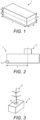
- a mineral wool slab 1 having a first layer of a first density disposed above a second layer of a second density.
- the slab 1 has a volume of 6.8 litres, although more generally for preferred embodiments the volume may be in the range of 3 litres to 20 litres, more preferably in the range 5 litres to 15 litres, and most preferably in the range 5 to 11 litres.
- Some embodiments comprise a slab with a volume in the range 6 litres to 8 litres. In other embodiments, the volume may lie in the range of 3 litres to 15 litres, or 3 litres to 10 litres, for example.
- An alternative preferred embodiment comprises a slab having a volume of 9 litres.
- the height h of the slab 1 of Figure 1 is 100mm, although more generally it may lie between 75mm to 150mm and more preferably between 85mm and 125mm.
- the width w of the slab 1 is 150mm, although this may more generally lie in the range of 100mm to 300mm, for example.
- the length l of the slab 1 is 450mm, although this value may also be varied, and may, for example, lie in the range of 200mm to 800mm, or preferably in the range 250mm to 600mm.
- a particular preferred embodiment comprises a slab 1 having a height h of 100mm, a width w of 150mm and a length / of 600mm.
- the first layer has a height a of 40mm and a density of 70kg/m 3 while the second layer has a height b of 60mm and a density of 50kg/m 3 .
- the height a of the first layer may lie in the range of 25mm to 50mm, while the height of the bottom layer may lie in the range of 50mm to 100mm.
- the density of the top layer is preferably in the range of 40kg/m 3 to 90kg/m 3 , more preferably 50kg/m 3 to 80kg/m 3
- the density of the bottom layer is preferably in the range of 35kg/m 3 to 85kg/m 3 , more preferably 45kg/m 3 to 75kg/m 3 .
- the height of the bottom layer is greater than that of the top layer.
- the ratios between the heights of the top and bottom layers may be 1:(1-3), or preferably 1:(1.2-2.5). More preferably, this ratio is 1:(1.2-1.8).
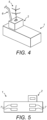
- the slab 1 is shown with a block 2 positioned on its upper surface.
- the slab 1 further comprises a liquid impermeable covering around the mineral wool, the covering having two openings. Firstly, there is an opening on the upper surface to allow contact between the mineral wool of the slab 1 and the block 2. Secondly, there is an opening on a lower surface which acts as a drain hole 3.
- the slab 1 is associated with only a single block 2 (i.e. one and only one block) for containing plants.
- a single block 2 i.e. one and only one block
- the environment of the plant or plants in a single block 2 can be directly managed more effectively.
- the drain hole 3 is provided at or adjacent to an edge of a lower surface of the slab 1.
- the position of the block 2 as measured from its central point is offset from that of the drain hole 3 by a distance x along the lengthy of the slab 1.
- the distance x is greater than 60% of the length l of the slab 1, and may be greater than 70% of this length although most preferably it is between 65% and 70%.
- the block 2 is offset from the position of the drain hole 3 by around 66.7% of the length of the slab.
- the length l of the slab 1 is 450mm, while the block 2 is placed at a distance of 300mm from the end of the slab 1 on which the drain hole 3 is disposed.
- the block 2 and the slab 1 are preferably formed of the same or a similar material.
- the block 2 may comprise stone wool and the binders and/or wetting agents described below.
- the block 2 has a volume of 1200ml. More generally the block may have a volume in the range of 50ml to 5000ml, more preferably 100ml to 3500ml, more preferably 250ml to 2500ml, and most preferably 100ml to 2000ml.
- the overall volume of the combination of the slab 1 and block 2 is preferably in the range of 6 to 11 litres.
- the block dimensions can be chosen in dependent on the plant to be grown.
- the preferred length and width of a block for pepper or cucumber plants is 10cm.
- the length is increased to 15cm.
- the height of the blocks is preferably in the range of 7 to 12cm, and more preferably in the range of 8 to 10cm.
- preferred dimensions for pepper and cucumber range from 10cm*10cm*7cm to 10cm*10cm*12cm, and more preferably from 10cm*10cm*8cm to 10cm*10cm*10cm. In terms of volume, therefore, the preferred range is 0.7 litres to 1.2 litres, more preferably 0.8 litres to 1 litre for cucumber and pepper plants. For tomato plants, the preferred dimensions range from 10cm*15cm*7cm to 10cm*15cm*12cm, and more preferably from 10cm*15cm*8cm to 10cm*15cm*10cm.
- the preferred range is 1.05 litres to 1.8 litres, more preferably 1.2 litres to 1.5 litres for tomato plants.
- the overall range of volumes for these crops is therefore preferably 0.7 litres to 1.8 litres, and more preferably 0.8 litres to 1.5 litres.
- the density of the block 2 is preferably in the range of 30kg/m 3 to 150kg/m 3 , more preferably in the range of 40kg/m 3 to 120kg/m 3 , and most preferably in the range of 50kg/m 3 to 100kg/m 3 .
- the height of a block 2 is preferably in the range 50mm to 160mm, more preferably in the range 60mm to 125mm and most preferably in the range 80mm to 100mm.
- the length and width of the block 2 may independently vary in the range 50mm to 250mm, preferably in the range 60mm to 200mm, and most preferably in the range 70mm to 150mm. These sizes and densities have been found to be effective for use in plant growth systems.
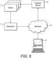
- Figure 3 illustrates a plant 5 in position within a plug 4 disposed within a block 2, such as that shown in Figure 2 .
- the plug 4 is typically formed of a mineral wool with a binder and/or wetting agent as described below in the context of the slab 1.
- the plug 4 is preferably cylindrical with a diameter of 20mm to 50mm, preferably 20mm to 40mm, and a height of 20mm to 50mm, preferably 25mm to 35mm.
- Each block 2 may in a preferred embodiment contain a single plant 5. However, it is possible that multiple plants 5 may be provided for each block 2, either by providing multiple plugs 4 each containing a single plant 5 or providing multiple plants in a single plug 4. In other preferred embodiments, a single plant is divided into two by splitting the stem of the plant at an early stage of growth.
- the plug 4 is not provided, and the seed is disposed directly within a hole in the block, from which the plant 5 subsequently grows.
- An example of a plant for which this approach is taken is the cucumber.
- the plant 5 is fruit or vegetable plant, such as a tomato plant or the like.
- the plant is a cucumber, aubergine or sweet pepper plant.
- the preferred embodiments of the present invention can increase the yield of fruit or vegetables from a plant and may also increase the quality of that fruit or vegetable.
- the slab 1 is a mineral wool slab.
- the mineral fibres employed may be any man-made vitreous fibres (MMVF), such as glass fibres, ceramic fibres, basalt fibres, slag wool, stone wool and others, but are usually stone wool fibres.
- Stone wool generally has a content of iron oxide at least 3% and content of alkaline earth metals (calcium oxide and magnesium oxide) from 10 to 40%, along with the other usual oxide constituents of mineral wool. These are silica; alumina; alkali metals (sodium oxide and potassium oxide) which are usually present in low amounts; and can also include titania and other minor oxides.
- the product can be formed of any of the types of man-made vitreous fibre which are conventionally known for production of growth substrates.
- the mineral wool is typically bound by a binding system which comprises a binder composition and additionally a wetting agent.
- the slab comprises mineral wool bound by a binder composition which, prior to curing, comprises: a) a sugar component, and b) a reaction product of a polycarboxylic acid component and an alkanolamine component, wherein the binder composition prior to curing contains at least 42% by weight of the sugar component based on the total weight (dry matter) of the binder components.
- This composition is included in the mineral wool which is to be used for the slab 1 and then cured, so that in the slab shown in Figure 1 the composition has been cured and so the components will have reacted.
- the slab contains a cured binder obtained by curing of the defined binder composition containing components (a) and (b) and the components of the binder composition discussed below refer to the composition prior to curing.
- the sugar component (a) employed in accordance with the present invention is preferably selected from sucrose and reducing sugars or mixtures thereof.
- a reducing sugar is any sugar that, in solution, has an aldehyde or a ketone group which allows the sugar to act as a reducing agent.
- reducing sugars may be present in the uncured binder composition as such or as a carbohydrate compound that yields one or more reducing sugars in situ under thermal curing conditions.
- the sugar or carbohydrate compound may be monosaccharide in its aldose or ketose form, a disaccharide, a triose, a tetrose, a pentose, a hexose, or a heptose; or a di-, oligo- or polysaccharide; or combinations thereof.
- Specific examples are glucose (i.e. dextrose), starch hydrolysates such as corn syrup, arabinose, xylose, ribose, galactose, mannose, frustose, maltose, lactose and invert sugar.
- Component (b) essentially comprises a reaction product of a polycarboxylic acid component and an alkanolamine component.
- the alkanolamine component is selected from diethanolamine, triethanolamine, diisopropanolamine, triisopropanolamine, methyldiethanolamine, ethyldiethanolamine, n-butyldiethanolamine, methyldiisopropanolamine, ethyl-isopropanolamine, ethyldi-isopropanolamine, 3-amino-1,2-propanediol, 2-amino-1,3-propanediol and tris(hydroxymethyl)aminomethane.
- the alkanolamine component is diethanolamine.
- the binder composition which is used in the products of the invention it is preferred to have the reaction product (b). However, in practice there is usually also some unreacted alkanolamine component present in the uncured binder composition.
- the polycarboxylic acid component is generally selected from dicarboxylic, tricarboxylic, tetracarboxylic, pentacarboxylic, and like polycarboxylic acids, and anhydrides, salts and combinations thereof.
- Preferred polycarboxylic acid components employed as starting materials for reacting with the other binder components are carboxylic anhydrides.
- the binder composition which is used in the products of the invention it is preferred to have the reaction product (b). However, in practice there is usually also some unreacted polycarboxylic acid component present in the uncured binder composition.
- a base may be added up to a pH of about 8, preferably a pH of between about 5-8, and more preferably a pH of about 6. Furthermore, the addition of a base will cause at least partial neutralisation of unreacted acids and a concomitant reduction of corrosiveness. Normally, the base will be added in an amount sufficient to achieve the desired water solubility or dilutability.
- the base is preferably selected from volatile bases which will evaporate at or below curing temperature and hence will not influence curing. Specific examples of suitable bases are ammonia (NH 3 ) and organic amines such as diethanolamine (DEA) and triethanolamine (TEA).
- the base is preferably added to the reaction mixture after the reaction between the alkanolamine and the carboxylic anhydride has been active stopped by adding water.
- An alternative binder composition may be based on a furan resin.
- a furanic binder composition is described in European patent EP0849987 .
- the furanic binder composition is both formaldehyde-free and hydrophilic, thereby offering particular advantages in the context of the present invention.
- binder systems comprising phenol-formaldehyde (PF), or particularly phenol-urea-formaldehyde (PUF), with or without dextrose may also be used where appropriate. These may include Ultra Low Formaldehyde (ULF) binders.
- PF phenol-formaldehyde
- PEF phenol-urea-formaldehyde
- ULF Ultra Low Formaldehyde
- the binding system preferably comprises a wetting agent.
- a wetting agent can be a non-ionic surfactant but preferably the wetting agent is an ionic surfactant.
- the wetting agent is not essential to provide a hydrophilic binder system. Accordingly, adequate water retention and re-saturation properties may be achieved without the wetting agent.
- the use of a wetting agent is preferred as it is found to increase the speed at which the slab may become saturated.
- the wetting agent is an anionic surfactant.
- anionic surfactants include salts (including, for example, sodium, potassium, ammonium and substituted ammonium salts such as mono-,di-and triethanolamine salts) of the anionic sulphate, sulphonate, carboxylate and sarcosinate surfactants.
- anionic surfactants include isethionates such as the acyl isethionates, N-acyl taurates, fatty acid amines of methyl tauride, alkyl succinates and sulfosuccinates, mono esters of sulfosuccinates, di-esters of sulfosuccinates and N-acyl sarcosinates.
- anionic sulphate surfactants and anionic sulphonate surfactants anionic carboxylate surfactants and anionic soap surfactants.
- anionic sulphonate surfactants such as linear or branched alkyl benzene sulphonates, alkyl ester sulphonates, primary or secondary alkylene sulphonates, olefin sulphonates, sulphonated polycarboxylic acids, alkyl glycerol sulphonates, fatty acyl glycerol sulphonates, fatty oleyl glycerol sulphonates and mixtures thereof.
- the anionic surfactant is a linear alkyl benzene sulphonate in which the alkyl chain has from 5 to 20 carbon atoms.
- the sodium and potassium salts are preferred.
- This type of surfactant provides particularly beneficial water distribution properties for growth substrates of relatively large height and also provides excellent re-saturation properties and does not lead to foaming problems in the irrigation water.
- Conventional non-ionic surfactants allow the growth substrate to take up water, but their water retaining capacity, water distribution over height and re-wetting properties are not as good as with this type of surfactant, preferred in the invention.
- the alkyl chain length is in the range 8 to 16, and more preferably at least 90% of the chains are in the range 10 to 13 and more preferably at least 90% (by weight) are in the range 10 to 12.
- the wetting agent comprises a linear alkyl benzene sulphonate and in this case the product is preferably produced by a method in which a polyol (such as monoethylene glycol) is included with the wetting agent in the mineral fibre product.
- a polyol such as monoethylene glycol
- the weight ratio of linear alkyl benzene sulphonate to monoethylene glycol (or other polyol - for instance propylene glycol or trimethylolpropane) is preferably 0.3:1 to 3.75:1, preferably 1:1 to 2:1.
- the polyol is normally evaporated during subsequent processing and curing and thus usually only trace amounts, if any, are present in the final product.
- the ionic surfactant may be cationic or zwitterionic.
- cationic surfactants include quaternary ammonium surfactants. These can, for instance, be selected from mono C6 to mono C16, preferably C6 to C10 N-alkyl or alkenyl ammonium surfactants wherein the remaining N positions are substituted by groups such as methyl, hydroxyethyl and hydroxypropyl.
- Suitable zwitterionic surfactants include derivatives of secondary and tertiary amines, derivatives of heterocyclic secondary and tertiary amines, or derivatives of quaternary ammonium, quaternary phosphonium or tertiary sulphonium compounds. Betaine and sultaine surfactants are examples of zwitterionic surfactants.
- the amount (by weight) of ionic surfactant based on the weight of binder (dry matter) is in the range 0.01 to 5%, preferably 0.1 to 4%.
- the ionic surfactant is present in the mineral fibre product in amounts preferably from 0.01 to 3% (by weight), based on mineral fibre product, more preferably 0.05 to 1%, in particular, 0.1 to 0.8%.
- the binder compositions used according to the present invention may additionally comprise one or more conventional binder additives.
- binder additives include, for instance, curing accelerators such as, e.g. ⁇ -hydroxyalkylamides; the free acid and salt forms of phosphoric acid, hypophosphorous acid and phosphonic acid.
- curing accelerators such as, e.g. ⁇ -hydroxyalkylamides
- Other strong acids such as boric acid, sulphuric acid, nitric acid and p-toluenesulphonic acid may also be used, either alone or in combination with the just-mentioned acids, in particular with phosphoric acid, hypophosphorous acid or phosphonic acid.
- binder additives are ammonia; silane coupling agents such as ⁇ -aminopropyltriethoxysilane; thermal stabilisers; UV stabilisers; plasticisers; anti-migration aids; coalescents; fillers and extenders such as clay, silicates and magnesium hydroxide; pigments such as titanium dioxide; flame retardants; corrosion inhibitors such as thiourea, urea; antifoaming agents; antioxidants; and others.
- binder additives and adjuvants may be used in conventional amounts generally not exceeding 20 wt.% of the binder solids.
- the amount of curing accelerator in the binder composition is generally between 0.05 and 5 wt.%, based on solids.
- the aqueous binder composition generally has a solids content of from 1 to 20 wt.% and a pH of 5 or greater.
- the mineral fibres employed may be any man-made vitreous fibres (MMVF), such as glass fibres, ceramic fibres, basalt fibres, slag wool, stone wool and others, but are usually stone wool fibres.
- Stone wool generally has a content of iron oxide at least 3% and content of alkaline earth metals (calcium oxide and magnesium oxide) from 10 to 40%, along with the other usual oxide constituents of mineral wool. These are silica; alumina; alkali metals (sodium oxide and potassium oxide) which are usually present in low amounts; and can also include titania and other minor oxides.
- the product can be formed of any of the types of man-made vitreous fibre which are conventionally known for production of growth substrates.
- the Loss on Ignition (LOI) of the slab is a measure of the amount of organic material such as binder and wetting agent present.
- the LOI of a dry sample may be measured using section 16 of BS2972, 1989 (Method 1).
- the LOI is preferably at least 2.5%, preferably up to 5.3%, especially preferably 3-4%. In particular, the most preferred LOI is 3.5%.
- the preferred LOI for the slab offers good strength, but with the binder described above plant growth is not negatively affected despite the higher level of binder.
- a higher LOI means the product is stronger. This means it is less likely to be damaged during use, especially during automated processing, for instance at a propagation facility.
- a further advantage of a higher binder content is that a smoother seed bed/hole can be formed in growth substrates such as plugs and blocks that are commonly provided with a seed hole.
- a smoother seed hole means that the seed is more likely to propagate from the ideal position in the seed bed/hole. The seed is additionally less likely to bounce out of the desired area, and/or be caught another part of the mineral fibre product. Accurate positioning of seeds leads to greater uniformity of the resulting crop which is advantageous for the propagator.
- the diameter of the fibres within the slab 1 is preferably in the range of 2 to 10 ⁇ m, more preferably in the range of 3 to 8 ⁇ m, and particularly preferably in the range of 4 to 7 ⁇ m. These values may apply equally to the diameter of the fibres in the block 2 and/or plug 4.
- the predominant fibre orientation of the first and second layers of the slab 1 is horizontal. This is found to reduce vertical nonuniformity in the water distribution.
- horizontal means parallel to the interfacial contact between the first and second layers.
- Alternative fibre orientations may be used in the first and/or second layers in other embodiments.
- Figure 4 shows a plant growth system comprising the slab 1, block 2 and plug 4 of Figures 1 to 3 and an irrigation device. The irrigation device 6 is arranged to provide a solution of water and nutrients to the system, directly to the block.
- solution from the irrigation device must pass more than 60% of the distance along the slab 1 before reaching the drain hole 3.
- the irrigation device 6 may be connected to separate nutrient and water reservoirs, and may be controlled to select the appropriate proportions of nutrients and water. Alternatively, a single combined nutrient and water reservoir may be provided such that the irrigation device provides liquid to the system having the same proportions of water and nutrients as are found in the reservoir.
- the control of the irrigation device is preferably effected using a control system.
- the control system may control the irrigation devices providing nutrients and water to a plurality of plant growth systems each comprising a slab 1 upon which a plant-containing block 2 is placed.
- the control system is controlled on the basis of the detected water nutrient levels in one or more of the slabs. Additional control may be carried out on the basis of detected water content levels and/or temperatures in one or more slabs.
- the locations of the detectors 7 used to detect these levels in one embodiment are illustrated in Figure 5 .
- the detectors 7 may be of a known type, and will typically comprise a body portion together with one or more, usually three probes which extend from the body into the slab.
- the probes are typically made from stainless steel or another conductive material, and are used to measure the water content and/or electrical conductivity (EC) levels of the substrate by analysing the substrate's temperature, resistance and/or capacitance.
- the EC levels can be used to infer the nutrient level within the solution in the slab 1 as they reflect the ionic content of that solution.
- the EC level is maintained in the range 1.2mS/cm to 8.5mS/cm, more preferably in the range 2mS/cm to 7mS/cm.
- the preferred EC levels may be chosen according to crop type. If EC is too low (e.g. less than 1.2mS/cm) the plant will starve for nutrients. If EC is in the range 2mS/cm to 3.5mS/cm, this will maximize production quantity. If EC is slightly higher this will result in better fruit quality (e.g. EC in the range 3.5mS/cm to 5mS/cm).
- the detectors 7 are placed on the upper surface of the slab 1, with the probes extending vertically through the slab.
- This approach is intended to provide a measurement which reflects the overall water or nutrient content across the vertical extent of the slab 1.
- probes typically return results which are disproportionally influenced by the conditions in one or more areas of the slab 1, such as in the top portion of the slab.
- One reason this disparity can arise is because of variation in the EC level across the slab 1, which clearly affects the measured electrical properties such as resistance and/or capacitance from which, for example, the water content is calculated.
- Figure 5 shows that the detectors 7 are disposed on the side of the slab 1 (i.e. the body portion of the detector 7 is disposed against a vertical face of the slab and the probes extend horizontally).
- This approach is available because of the improved water content and EC distributions within the slab 1. Since these are substantially uniform in the slab 1 of the preferred embodiment, the horizontal extent of the probes provides an accurate reading.
- the slab 1 of Figure 5 is illustrated with a plurality of detectors 7, this is not the case in all preferred embodiments.
- the array of detectors 7 shown in Figure 5 allows measurement of the water content distribution and EC distribution, and has been used to analyse the slab 1 characteristics, providing results such as those detailed below. However, in practice it is found that only a single detector 7 may be required.
- This detector 7 preferably comprises horizontally extending probes located at a position offset from the block towards the drain hole 3.
- the detector 7 is located at a distance of 200mm from the drain hole 3 and 100mm from the block 2. The positions of the block 2 and the detector 7 in this context are measured from their central points.
- the detectors 7 are used to control the quantity of water provided to the slab 1 by using a control system such as that illustrated in Figure 6 .
- the control system may also vary the concentration of nutrients within the solution provided by the irrigation devices 6 to the slabs 1.
- the detectors 7 observe the data in the slabs 1, and communicate this across a network 8 to a control unit 9.
- the control unit drives the irrigation devices (drippers) 6 across the network 8 in order to provide water and nutrients to the slabs 1.
- the control unit 9 can be programmed with a desired irrigation strategy (as discussed in more detail below) and can automatically ensure that the irrigation is carried out to control the nutrient levels in the slab 1 and may also control the water content levels in this manner. In this way, an automatic control of the irrigation process to provide a desired result is achieved.
- each control system will comprise a large number of slabs 1.
- the detectors 1 are fixedly mounted to the slabs 1, in order that they can provide results to the control unit 9 at regular intervals. For example, the detectors may provide results at intervals of one minute, five minutes or another suitable time period. This allows the slabs 1 within the system to be constantly monitored so that they can be irrigated appropriately.
- the irrigation devices 6 of the system may be controlled to apply a specific irrigation strategy.
- a specific irrigation strategy may comprise a number of distinct phases, designed to steer plants through generative and vegetative growth.
- generative growth refers to a type of growth in which the production of flowers/fruit is encouraged, while during vegetative growth the plant a higher proportion of leaves and other green elements are produced.
- Generative growth is encouraged when a plant has a relative lack of water and/or nutrients, while vegetative growth is encouraged by a plentiful supply of water and/or nutrients.
- Vegetative growth produces the higher increase in overall biomass of the plant, while generative growth increases the proportion of the growth which contributes to the production of fruit or flowers.
- the plant growth substrate is watered each day in an attempt to reach a desired water content level.
- the water content of the substrate is measured as a percentage of the water content of the substrate when the substrate is fully saturated. Thus, a value of 0% represents a dry substrate, while a value of 100% represents a fully saturated substrate.
- an irrigation strategy of this type comprises a number of distinct stages. Firstly, prior to placing the block 2 on the slab 1, the slab 1 is typically saturated or near-saturated with water. This helps to ensure that when the block 2 is first placed on the slab 1, root growth into the slab 1 is encouraged. At this point, however, the grower is anxious to ensure that the plant 5 provides fruit as soon as possible. In order to achieve this, the grower aims to impart a "generative impulse” (i.e. an impulse to initiate generative growth). This is done during a first period of the irrigation strategy, by reducing the desired water content down to a minimum level before increasing it again. The principle is that the reduction of water content will encourage generative growth of the plant and thus the flowering of the plant leading to fruit at the earliest available time.
- a "generative impulse" i.e. an impulse to initiate generative growth
- the second period corresponds broadly to the summer season, during which the relatively high amount of sunshine causes the plants to transpire at a greater rate. Accordingly, a relatively high proportion of water must be provided to the plants. It should be recognised that although growth may be steered towards vegetative growth during this period more than at other periods, fruit continues to grow, although the rate is controlled by this steering. As the season turns to autumn and then winter, the transpiration rate reduces. As a result, it is no longer necessary to maintain the same water content in the substrate. Moreover, there is at this stage a desire to encourage further fruit growth before the plant reaches the end of the cycle. For both these reasons, the irrigation strategy may comprise a third period in which the water content level is reduced. The rate of reduction is relatively gradual.
- the reduction in water content during the third period encourages generative growth in the plant, and thereby extends the season during which useful fruit can be obtained from the plant.
- irrigation strategies can be used to attempt to steer the plant between generative and vegetative growth states in order to increase the yield of fruit obtained from the plant.
- this process has been carried out by driving water content levels within the substrate to desired levels.
- the inventors of the present invention have identified a link between variation of water content levels and the nutrient levels within the slabs that can lead to sub-optimal results.
- reduction in water content levels can lead to increased nutrient levels which it has been discovered can inhibit plant growth.
- the level of water provided to the slab is controlled with a dependence on nutrient levels in order to avoid unwanted effects.
- FIGS 7A, 7B , 8 , 9 and 10 demonstrate the results of a long term study into the effects of irrigation strategies.
- Figures 7A and 7B illustrate two plant growth substrates used for comparison. The plant growth substrates were used to grow tomato plants. As can be seen from the figures, each system comprised a single drain hole at one end of the slab.
- the first example system of Figure 7A comprises three separate blocks placed on the upper surface of the slab, whereas the second example system of Figure 7B comprises only a single block.
- the first example slab of Figure 7A has dimensions of 1330mm*195mm*75mm (length*width*height) while the blocks have dimensions of 100mm*100mm*65mm (length*width*height).
- the blocks are located at positions of 150mm to 200mm, 650mm to 700mm and 1100 to 1150mm along the slab away from the drain hole (as measured from the centre of the block) and irrigation devices are provided for each block to deliver a water and nutrient solution to the block at a distal side of the block to the drain hole.
- the second example slab of Figure 7B has dimensions of 450mm*150mm*100mm (length*width*height) while the block has dimensions of 100mm*100mm*65mm (length*width*height).
- the block is located 300mm along the slab away from the drain hole (as measured from the centre of the block) and an irrigation device is provided to deliver a water and nutrient solution to the block at a distal side of the block to the drain hole.
- Figure 8 illustrates the measured water content in the first example slab (dashed line) and the second example slab (unbroken line) over the course of the study. It can be seen that during a first period the water content was reduced from an initial relatively high point, before subsequently increasing in line with the concept of a generative impulse as described above.
- Figure 9 shows the measured EC level during the study for the first example substrate (dashed line) and the second example substrate (unbroken line). It will be recalled that the EC level represents in the nutrient level in the slab. It is noticeable that the EC level rapidly increases during the initial phase in which the generative impulse is applied to the plants. This increase leads to a peak EC level above that which is generally expected during later phases of the irrigation strategy.
- FIG. 10 shows the leaf length measured during the study for both the first example (dashed line) and second example (unbroken line).
- a clear drop in leaf length is observed at around 5 weeks in to the study. This drop is associated with the increased EC level shown during this period. It is thus understood that the EC level has an effect on the growth of the plant. Since the EC level has also been shown to be altered by changed in the water content level, it is desirable to control the water applied to the plant in such a way as to maintain the EC level within a desirable range. This contrasts with prior art approaches which may alter the concentration of nutrients to achieve a desired EC level but do not recognise that the overall quantity of water applied should be restrained by the desired nutrient content of the substrate.
Landscapes
- Life Sciences & Earth Sciences (AREA)
- Environmental Sciences (AREA)
- Engineering & Computer Science (AREA)
- Water Supply & Treatment (AREA)
- Biodiversity & Conservation Biology (AREA)
- Botany (AREA)
- Ecology (AREA)
- Forests & Forestry (AREA)
- Hydroponics (AREA)
- Cultivation Of Plants (AREA)
- Cultivation Receptacles Or Flower-Pots, Or Pots For Seedlings (AREA)
Claims (15)
- Pflanzenwachstumssystem, umfassend:ein oder mehrere Pflanzenwachstumssubstrate (1, 2);einen oder mehrere Detektoren (7), die angeordnet sind, um die Nährstoffniveaus von wenigstens einem der Pflanzenwachstumssubstrate (1, 2) zu überwachen;wenigstens eine Bewässerungsvorrichtung (6), die angeordnet ist, um den Pflanzenwachstumssubstraten (1, 2) Wasser zuzuführen; undein Steuermittel (9), das mit den Detektoren (7) und der wenigstens einen Bewässerungsvorrichtung (6) verbunden ist,wobei:jedes Substrat (1, 2) eine Platte (1) aus künstlichen Glasfasern, MMVF, und einen einzelnen Block (2) aus künstlichen Glasfasern, MMVF, umfasst, und der Block (2) mehr als 60 % der Länge der Platte (1) von einem Abflussloch (3) der Platte positioniert ist, wie von dem Mittelpunkt des Blocks gemessen;die Bewässerungsvorrichtung angeordnet ist, um dem Block Wasser zuzuführen; unddie Zufuhr von Wasser durch die wenigstens eine Bewässerungsvorrichtung (6) von dem Steuermittel (9) in Abhängigkeit von den überwachten Nährstoffniveaus gesteuert wird, wobei der eine oder die mehreren Detektoren (7) angeordnet sind, um den Nährstoffgehalt aus einer elektrischen Leitfähigkeit von Fluid in wenigstens einem Pflanzenwachstumssubstrat (1, 2) zu bestimmen, und wobei das Niveau der elektrischen Leitfähigkeit innerhalb eines vorbestimmten Bereichs gehalten wird.
- Pflanzenwachstumssystem nach Anspruch 1, wobei der Block (2) zwischen 65 % und 70 % der Länge der Platte (1) von einem Abflussloch (3) der Platte positioniert ist.
- Pflanzenwachstumssystem nach Anspruch 1, wobei der Block (2) 66,7 % der Länge der Platte (1) von einem Abflussloch (3) der Platte positioniert ist.
- Pflanzenwachstumssystem nach einem der vorhergehenden Ansprüche, wobei der eine oder die mehreren Detektoren (7) ferner angeordnet sind, um die Wassergehaltsniveaus von wenigstens einem der Pflanzenwachstumssubstrate (1, 2) zu überwachen, und die Zufuhr von Wasser durch die wenigstens eine Bewässerungsvorrichtung (6) durch das Steuermittel (9) in Abhängigkeit von den überwachten Wassergehaltsniveaus gesteuert wird.
- Pflanzenwachstumssystem nach einem der vorhergehenden Ansprüche,
wobei die wenigstens eine Bewässerungsvorrichtung (6) ferner angeordnet ist, um den Pflanzenwachstumssubstraten (1, 2) Nährstoffe bereitzustellen. - Pflanzenwachstumssystem nach Anspruch 5, wobei die Zufuhr von Nährstoffen durch die wenigstens eine Bewässerungsvorrichtung (6) von dem Steuermittel (9) in Abhängigkeit von den überwachten Nährstoffniveaus gesteuert wird.
- Pflanzenwachstumssystem nach einem der vorhergehenden Ansprüche, wobei der eine oder die mehreren Detektoren (7) ferner angeordnet sind, um die Verteilung von wenigstens einem von Wasser oder Nährstoffen in wenigstens einem der Pflanzenwachstumssubstrate (1) zu überwachen.
- Pflanzenwachstumssystem nach einem der vorhergehenden Ansprüche, wobei der eine oder die mehreren Detektoren (7) ferner angeordnet sind, um die Temperatur von wenigstens einem der Pflanzenwachstumssubstrate (1, 2) zu überwachen, und die Zufuhr von Wasser durch die wenigstens eine Bewässerungsvorrichtung (6) ferner durch das Steuermittel (9) in Abhängigkeit von der überwachten Temperatur gesteuert wird.
- Pflanzenwachstumssystem nach Anspruch 1, wobei die Platte ein Volumen in dem Bereich von 3 bis 20 Liter aufweist.
- Pflanzenwachstumssystem nach Anspruch 9, wobei jedes Pflanzenwachstumssubstrat (1) ferner einen einzelnen Stopfen (4) aus künstlichen Glasfasern, MMVF, umfasst, der in dem Block aus künstlichen Glasfasern, MMVF, angeordnet ist.
- Pflanzenwachstumssystem nach einem der vorhergehenden Ansprüche, wobei jede MMVF-Platte (1) eine erste Schicht aus künstlichen Glasfasern, MMVF, umfasst, die in Grenzflächenkontakt mit einer zweiten Schicht aus künstlichen Glasfasern, MMVF, steht, wobei die erste Schicht eine höhere Dichte als die zweite Schicht aufweist.
- Pflanzenwachstumssystem nach Anspruch 11, wobei die erste Schicht aus künstlichen Glasfasern, MMVF, eine Dichte in dem Bereich von 40 bis 90 kg/m3 aufweist und die zweite Schicht aus künstlichen Glasfasern, MMVF, eine Dichte in dem Bereich von 35 bis 85 kg/m3 aufweist.
- Pflanzenwachstumssystem nach einem der vorhergehenden Ansprüche, wobei jede Platte (1) aus künstlichen Glasfasern, MMVF, ein Bindesystem umfasst, das ein organisches Bindemittel umfasst, ausgewählt aus formaldehydfreien Bindemitteln.
- Pflanzenwachstumssystem nach einem der vorhergehenden Ansprüche, wobei zwei oder mehr Detektoren (7) angeordnet sind, um sich durch eine Seitenwand der Platte (1) zu erstrecken, sodass in Verwendung die Nährstoffniveaus auf verschiedenen Höhen der Platte (1) überwacht werden.
- Verfahren zum Verwalten der Bewässerung eines Pflanzenwachstumssystems nach Anspruch 1, wobei das Verfahren umfasst:Überwachen von Nährstoffniveaus von wenigstens einem der Pflanzenwachstumssubstrate;Zuführen von Wasser zu den Pflanzenwachstumssubstraten (1, 2), wobei die Zufuhr von Wasser in Abhängigkeit von den überwachten Nährstoffniveaus gesteuert wird;wobei das Überwachen von Nährstoffniveaus das Bestimmen des Nährstoffgehalts aus einer elektrischen Leitfähigkeit von Fluid in wenigstens einem Pflanzenwachstumssubstrat (1, 2) umfasst;wobei das EC-Niveau innerhalb eines vorbestimmten Bereichs gehalten wird.
Priority Applications (1)
| Application Number | Priority Date | Filing Date | Title |
|---|---|---|---|
| EP14703823.6A EP2953447B1 (de) | 2013-02-08 | 2014-02-07 | Pflanzenwachstumssystem |
Applications Claiming Priority (3)
| Application Number | Priority Date | Filing Date | Title |
|---|---|---|---|
| EP13154725 | 2013-02-08 | ||
| EP14703823.6A EP2953447B1 (de) | 2013-02-08 | 2014-02-07 | Pflanzenwachstumssystem |
| PCT/EP2014/052487 WO2014122292A1 (en) | 2013-02-08 | 2014-02-07 | Plant growth system |
Publications (3)
| Publication Number | Publication Date |
|---|---|
| EP2953447A1 EP2953447A1 (de) | 2015-12-16 |
| EP2953447C0 EP2953447C0 (de) | 2025-04-23 |
| EP2953447B1 true EP2953447B1 (de) | 2025-04-23 |
Family
ID=47722070
Family Applications (1)
| Application Number | Title | Priority Date | Filing Date |
|---|---|---|---|
| EP14703823.6A Active EP2953447B1 (de) | 2013-02-08 | 2014-02-07 | Pflanzenwachstumssystem |
Country Status (10)
| Country | Link |
|---|---|
| US (1) | US10492388B2 (de) |
| EP (1) | EP2953447B1 (de) |
| JP (1) | JP6389476B2 (de) |
| CN (1) | CN105120654B (de) |
| AU (1) | AU2014213971B2 (de) |
| CA (1) | CA2899156C (de) |
| ES (1) | ES3028871T3 (de) |
| PL (1) | PL2953447T3 (de) |
| RU (1) | RU2649855C2 (de) |
| WO (1) | WO2014122292A1 (de) |
Families Citing this family (13)
| Publication number | Priority date | Publication date | Assignee | Title |
|---|---|---|---|---|
| CN105357951A (zh) | 2013-07-05 | 2016-02-24 | 罗克伍尔国际公司 | 植物生长系统 |
| RU2018127511A (ru) * | 2015-12-29 | 2020-01-30 | Роквул Интернэшнл А/С | Ростовой субстратный продукт |
| CA3029773A1 (en) | 2016-07-04 | 2018-01-11 | Rockwool International A/S | Plant growth control system |
| US11606916B2 (en) | 2016-12-23 | 2023-03-21 | Cultivation Systems B.V. | Grooved stackable panel for floating cultivation of plants |
| US11136451B2 (en) | 2017-10-09 | 2021-10-05 | Owens Corning Intellectual Capital, Llc | Aqueous binder compositions |
| KR20210071018A (ko) | 2018-09-28 | 2021-06-15 | 락울 인터내셔날 에이/에스 | 식물 성장 제어 시스템 |
| WO2020210191A1 (en) | 2019-04-09 | 2020-10-15 | Owens Corning Intellectual Capital, Llc | Insulation products formed with aqueous binder compositions |
| US12297342B2 (en) | 2019-12-09 | 2025-05-13 | Owens Corning Intellectual Capital, Llc | Fiberglass insulation product |
| US11813833B2 (en) | 2019-12-09 | 2023-11-14 | Owens Corning Intellectual Capital, Llc | Fiberglass insulation product |
| PL4084602T3 (pl) * | 2019-12-30 | 2023-09-25 | Rockwool A/S | Sposób rozmnażania sadzonek konopi |
| AU2021352425A1 (en) | 2020-10-01 | 2023-05-18 | Owens Corning Intellectual Capital, Llc | B-stageable aqueous binder compositions |
| JP7452870B2 (ja) * | 2021-04-01 | 2024-03-19 | 株式会社誠和 | 株元保護資材及び果菜類の栽培方法 |
| IT202200005237A1 (it) * | 2022-03-17 | 2023-09-17 | Valente S R L | Un metodo di coltivazione |
Citations (1)
| Publication number | Priority date | Publication date | Assignee | Title |
|---|---|---|---|---|
| EP0628243A1 (de) * | 1993-06-09 | 1994-12-14 | Isover Saint-Gobain | Erdloses Kultursystem und Verfahren zur Wiederverwendung eines solchen Systems |
Family Cites Families (39)
| Publication number | Priority date | Publication date | Assignee | Title |
|---|---|---|---|---|
| NL8701589A (nl) * | 1987-07-06 | 1989-02-01 | Rockwool Lapinus Bv | Werkwijze en inrichting voor de minerale-wol-teelt van planten met zuigspanningsregeling. |
| CA1332000C (en) * | 1988-10-04 | 1994-09-13 | Nicola Liburdi | Computerized fertilizer injector system |
| JP2592969B2 (ja) * | 1989-12-12 | 1997-03-19 | 株式会社東芝 | 養液制御装置 |
| NL9100161A (nl) * | 1991-01-30 | 1992-08-17 | Rockwool Grodan Bv | Plantpot voor het telen van planten. |
| DK156692D0 (da) * | 1992-12-29 | 1992-12-29 | Rockwool Int | Mineralfiberprodukt |
| GB9323751D0 (en) * | 1993-09-20 | 1994-01-05 | Fudger Michael E | Hydroponic control apparatus |
| PL185080B1 (pl) | 1995-08-30 | 2003-02-28 | Rockwool Int | Podłoże wzrostowe dla roślin |
| JPH09168340A (ja) * | 1995-12-19 | 1997-06-30 | Kochi Pref Gov | 養液栽培方法及びその装置 |
| JPH09271278A (ja) | 1996-04-01 | 1997-10-21 | Nitto Boseki Co Ltd | ロックウール栽培床 |
| JP3505046B2 (ja) * | 1996-09-30 | 2004-03-08 | 日本たばこ産業株式会社 | バレイショ塊茎生産方法 |
| GB0117183D0 (en) * | 2001-07-13 | 2001-09-05 | Rockwool Int | Method and apparatus for growing plants |
| GB0117182D0 (en) | 2001-07-13 | 2001-09-05 | Rockwool Int | Method and system for growing plants |
| RU2281647C2 (ru) * | 2001-12-04 | 2006-08-20 | ГНЦ РФ ВНИИ растениеводства им. П.И. Вавилова | Способ гидропонного выращивания c3-растений |
| AU2003902836A0 (en) * | 2003-06-06 | 2003-06-26 | M.B.T.L. Limited | Environmental sensor |
| JP2005117999A (ja) | 2003-10-20 | 2005-05-12 | Kazuo Matsuura | 全自動植物栽培制御装置 |
| US7363112B2 (en) | 2004-05-10 | 2008-04-22 | Brent Arthur Cartwright | Digital moisture monitor controller with wide applications soil, and hydroponics moisture sensors, and optional X10 multi-sensor, multi-pump controller |
| US7809475B2 (en) * | 2004-12-20 | 2010-10-05 | Fw Enviro, Llc | Computer controlled fertigation system and method |
| US10085393B2 (en) * | 2005-02-04 | 2018-10-02 | The Toro Company | Long range, battery powered, wireless environmental sensor interface devices |
| EP1880597A1 (de) * | 2006-07-20 | 2008-01-23 | Rockwool International A/S | Zuchtsubstrate, ihre Herstellung und ihre Verwendung |
| EP1880598A1 (de) * | 2006-07-20 | 2008-01-23 | Rockwool International A/S | Zuchtsubstrate, ihre Herstellung und ihre Verwendung |
| EP1897433A1 (de) | 2006-09-06 | 2008-03-12 | Rockwool International A/S | Wässrige Bindemittel-Zusammensetzung für Mineralfasern |
| EP2146566A2 (de) | 2007-04-10 | 2010-01-27 | Croptimize APS | Hydroponisches system |
| EP2044835A1 (de) * | 2007-10-03 | 2009-04-08 | Nederlandse Organisatie voor toegepast- natuurwetenschappelijk onderzoek TNO | Glashaussystem |
| EP2080431A1 (de) * | 2008-01-18 | 2009-07-22 | Rockwool International A/S | Verfahren zum Züchten einer Pflanze |
| EP2111746A1 (de) | 2008-04-22 | 2009-10-28 | Rockwool International A/S | Verfahren zum Züchten einer Pflanze |
| NL2001568C2 (nl) | 2008-05-08 | 2009-11-11 | Hevorma B V | Groei-inrichting voor gewas en bekleding of bouwdeel vervaardigd daarmee. |
| EP2166347A1 (de) | 2008-09-18 | 2010-03-24 | Rockwool International A/S | Vorrichtung zur Messung des Substratwassergehalts |
| CA2642183A1 (en) | 2008-10-22 | 2010-04-22 | Genevieve Noel | Modular support for plants |
| US7823328B2 (en) * | 2009-02-27 | 2010-11-02 | Zack Allen Walhovd | Aeroponic plant growing system |
| JP5679254B2 (ja) | 2009-11-30 | 2015-03-04 | サントリーホールディングス株式会社 | 植栽装置、および給水制御方法 |
| US8752327B2 (en) * | 2010-05-11 | 2014-06-17 | Nissim Daniely | Oxygen availability-based irrigation system |
| US8365462B2 (en) * | 2011-05-31 | 2013-02-05 | Heliae Development, Llc | V-Trough photobioreactor systems |
| US20130019527A1 (en) * | 2011-07-21 | 2013-01-24 | Ingrid Howe-Sylvain | Mobile, Automatic Plant Growth System |
| CA2856199C (en) * | 2011-12-22 | 2019-10-01 | Rockwool International A/S | Plant growth method |
| SI2793556T1 (sl) * | 2011-12-22 | 2020-12-31 | Rockwool International A/S | Substrat za rast rastlin |
| SI2793555T1 (sl) * | 2011-12-22 | 2021-08-31 | Rockwool International A/S | Substrat za rast rastlin |
| US9149005B2 (en) * | 2011-12-22 | 2015-10-06 | Rockwool International A/S | Plant growth system |
| CA2856360C (en) * | 2011-12-22 | 2019-07-02 | Rockwool International A/S | Plant growth system |
| CN202617890U (zh) | 2012-02-02 | 2012-12-26 | 费耀 | 营养液循环立柱式植物种植设备 |
-
2014
- 2014-02-07 RU RU2015138133A patent/RU2649855C2/ru active
- 2014-02-07 JP JP2015556517A patent/JP6389476B2/ja active Active
- 2014-02-07 EP EP14703823.6A patent/EP2953447B1/de active Active
- 2014-02-07 US US14/765,036 patent/US10492388B2/en active Active
- 2014-02-07 CN CN201480007945.4A patent/CN105120654B/zh active Active
- 2014-02-07 AU AU2014213971A patent/AU2014213971B2/en active Active
- 2014-02-07 PL PL14703823.6T patent/PL2953447T3/pl unknown
- 2014-02-07 CA CA2899156A patent/CA2899156C/en active Active
- 2014-02-07 WO PCT/EP2014/052487 patent/WO2014122292A1/en not_active Ceased
- 2014-02-07 ES ES14703823T patent/ES3028871T3/es active Active
Patent Citations (1)
| Publication number | Priority date | Publication date | Assignee | Title |
|---|---|---|---|---|
| EP0628243A1 (de) * | 1993-06-09 | 1994-12-14 | Isover Saint-Gobain | Erdloses Kultursystem und Verfahren zur Wiederverwendung eines solchen Systems |
Non-Patent Citations (2)
| Title |
|---|
| ANDREW LEE: "Understanding Substrate Design", PRACTICAL HYDROPONICS & GREENHOUSES, 1 November 2009 (2009-11-01), pages 56 - 59, XP055299867 * |
| ANONYMOUS: "What to know about the Uni-Slab", GRODAN, 13 December 2011 (2011-12-13), pages 1 - 2, XP055299854, Retrieved from the Internet <URL:http://grodan101.com/growing-tips/grow/what-know-about-uni-slab/> [retrieved on 20160905] * |
Also Published As
| Publication number | Publication date |
|---|---|
| CN105120654B (zh) | 2019-04-09 |
| JP2016506741A (ja) | 2016-03-07 |
| AU2014213971A1 (en) | 2015-08-06 |
| PL2953447T3 (pl) | 2025-06-02 |
| WO2014122292A1 (en) | 2014-08-14 |
| CN105120654A (zh) | 2015-12-02 |
| CA2899156A1 (en) | 2014-08-14 |
| EP2953447C0 (de) | 2025-04-23 |
| US20150373936A1 (en) | 2015-12-31 |
| AU2014213971B2 (en) | 2017-06-29 |
| ES3028871T3 (en) | 2025-06-20 |
| RU2649855C2 (ru) | 2018-04-05 |
| CA2899156C (en) | 2020-12-29 |
| RU2015138133A (ru) | 2017-03-15 |
| EP2953447A1 (de) | 2015-12-16 |
| JP6389476B2 (ja) | 2018-09-12 |
| US10492388B2 (en) | 2019-12-03 |
Similar Documents
| Publication | Publication Date | Title |
|---|---|---|
| EP2953447B1 (de) | Pflanzenwachstumssystem | |
| CA2856199C (en) | Plant growth method | |
| CA2856359C (en) | Plant growth system | |
| CA2866247C (en) | Plant growth substrates | |
| CA2856360C (en) | Plant growth system | |
| CA2853958C (en) | Plant growth substrate | |
| EP2793554B1 (de) | Pflanzenwachstumssubstrat |
Legal Events
| Date | Code | Title | Description |
|---|---|---|---|
| PUAI | Public reference made under article 153(3) epc to a published international application that has entered the european phase |
Free format text: ORIGINAL CODE: 0009012 |
|
| 17P | Request for examination filed |
Effective date: 20150716 |
|
| AK | Designated contracting states |
Kind code of ref document: A1 Designated state(s): AL AT BE BG CH CY CZ DE DK EE ES FI FR GB GR HR HU IE IS IT LI LT LU LV MC MK MT NL NO PL PT RO RS SE SI SK SM TR |
|
| AX | Request for extension of the european patent |
Extension state: BA ME |
|
| DAX | Request for extension of the european patent (deleted) | ||
| RAP1 | Party data changed (applicant data changed or rights of an application transferred) |
Owner name: ROCKWOOL INTERNATIONAL A/S |
|
| STAA | Information on the status of an ep patent application or granted ep patent |
Free format text: STATUS: EXAMINATION IS IN PROGRESS |
|
| 17Q | First examination report despatched |
Effective date: 20210601 |
|
| RAP3 | Party data changed (applicant data changed or rights of an application transferred) |
Owner name: ROCKWOOL A/S |
|
| GRAP | Despatch of communication of intention to grant a patent |
Free format text: ORIGINAL CODE: EPIDOSNIGR1 |
|
| STAA | Information on the status of an ep patent application or granted ep patent |
Free format text: STATUS: GRANT OF PATENT IS INTENDED |
|
| INTG | Intention to grant announced |
Effective date: 20241113 |
|
| GRAS | Grant fee paid |
Free format text: ORIGINAL CODE: EPIDOSNIGR3 |
|
| GRAA | (expected) grant |
Free format text: ORIGINAL CODE: 0009210 |
|
| STAA | Information on the status of an ep patent application or granted ep patent |
Free format text: STATUS: THE PATENT HAS BEEN GRANTED |
|
| AK | Designated contracting states |
Kind code of ref document: B1 Designated state(s): AL AT BE BG CH CY CZ DE DK EE ES FI FR GB GR HR HU IE IS IT LI LT LU LV MC MK MT NL NO PL PT RO RS SE SI SK SM TR |
|
| REG | Reference to a national code |
Ref country code: GB Ref legal event code: FG4D |
|
| REG | Reference to a national code |
Ref country code: CH Ref legal event code: EP |
|
| REG | Reference to a national code |
Ref country code: DE Ref legal event code: R096 Ref document number: 602014091824 Country of ref document: DE |
|
| REG | Reference to a national code |
Ref country code: IE Ref legal event code: FG4D |
|
| U01 | Request for unitary effect filed |
Effective date: 20250514 |
|
| U07 | Unitary effect registered |
Designated state(s): AT BE BG DE DK EE FI FR IT LT LU LV MT NL PT RO SE SI Effective date: 20250520 |
|
| REG | Reference to a national code |
Ref country code: ES Ref legal event code: FG2A Ref document number: 3028871 Country of ref document: ES Kind code of ref document: T3 Effective date: 20250620 |
|
| PG25 | Lapsed in a contracting state [announced via postgrant information from national office to epo] |
Ref country code: GR Free format text: LAPSE BECAUSE OF FAILURE TO SUBMIT A TRANSLATION OF THE DESCRIPTION OR TO PAY THE FEE WITHIN THE PRESCRIBED TIME-LIMIT Effective date: 20250724 |
|
| PG25 | Lapsed in a contracting state [announced via postgrant information from national office to epo] |
Ref country code: HR Free format text: LAPSE BECAUSE OF FAILURE TO SUBMIT A TRANSLATION OF THE DESCRIPTION OR TO PAY THE FEE WITHIN THE PRESCRIBED TIME-LIMIT Effective date: 20250423 |
|
| PG25 | Lapsed in a contracting state [announced via postgrant information from national office to epo] |
Ref country code: RS Free format text: LAPSE BECAUSE OF FAILURE TO SUBMIT A TRANSLATION OF THE DESCRIPTION OR TO PAY THE FEE WITHIN THE PRESCRIBED TIME-LIMIT Effective date: 20250723 |
|
| PG25 | Lapsed in a contracting state [announced via postgrant information from national office to epo] |
Ref country code: IS Free format text: LAPSE BECAUSE OF FAILURE TO SUBMIT A TRANSLATION OF THE DESCRIPTION OR TO PAY THE FEE WITHIN THE PRESCRIBED TIME-LIMIT Effective date: 20250823 |