EP2953341A2 - Dispositif d'affichage, dispositif mobile, système comprenant celui-ci et son procédé de mise en correspondance de qualité d'image - Google Patents
Dispositif d'affichage, dispositif mobile, système comprenant celui-ci et son procédé de mise en correspondance de qualité d'image Download PDFInfo
- Publication number
- EP2953341A2 EP2953341A2 EP15153067.2A EP15153067A EP2953341A2 EP 2953341 A2 EP2953341 A2 EP 2953341A2 EP 15153067 A EP15153067 A EP 15153067A EP 2953341 A2 EP2953341 A2 EP 2953341A2
- Authority
- EP
- European Patent Office
- Prior art keywords
- image
- display device
- image quality
- displayed
- correction value
- Prior art date
- Legal status (The legal status is an assumption and is not a legal conclusion. Google has not performed a legal analysis and makes no representation as to the accuracy of the status listed.)
- Granted
Links
- 238000000034 method Methods 0.000 title claims abstract description 50
- 238000012937 correction Methods 0.000 claims abstract description 162
- 238000004891 communication Methods 0.000 claims description 64
- 239000003086 colorant Substances 0.000 description 22
- 230000008569 process Effects 0.000 description 15
- 230000004044 response Effects 0.000 description 9
- 239000000470 constituent Substances 0.000 description 6
- 230000004913 activation Effects 0.000 description 4
- 238000010586 diagram Methods 0.000 description 4
- 230000006870 function Effects 0.000 description 4
- 239000004973 liquid crystal related substance Substances 0.000 description 4
- 230000005540 biological transmission Effects 0.000 description 2
- 230000000694 effects Effects 0.000 description 2
- 239000011159 matrix material Substances 0.000 description 2
- 238000012986 modification Methods 0.000 description 2
- 230000004048 modification Effects 0.000 description 2
- 238000012546 transfer Methods 0.000 description 2
- OKTJSMMVPCPJKN-UHFFFAOYSA-N Carbon Chemical compound [C] OKTJSMMVPCPJKN-UHFFFAOYSA-N 0.000 description 1
- 238000010521 absorption reaction Methods 0.000 description 1
- 230000002457 bidirectional effect Effects 0.000 description 1
- 239000002041 carbon nanotube Substances 0.000 description 1
- 229910021393 carbon nanotube Inorganic materials 0.000 description 1
- 238000006243 chemical reaction Methods 0.000 description 1
- 230000000295 complement effect Effects 0.000 description 1
- 239000002131 composite material Substances 0.000 description 1
- 230000003247 decreasing effect Effects 0.000 description 1
- 238000012217 deletion Methods 0.000 description 1
- 230000037430 deletion Effects 0.000 description 1
- 230000001419 dependent effect Effects 0.000 description 1
- 238000000605 extraction Methods 0.000 description 1
- 238000007689 inspection Methods 0.000 description 1
- 238000009434 installation Methods 0.000 description 1
- 239000002159 nanocrystal Substances 0.000 description 1
- 230000006855 networking Effects 0.000 description 1
- 238000012545 processing Methods 0.000 description 1
- 230000009467 reduction Effects 0.000 description 1
- 239000004065 semiconductor Substances 0.000 description 1
- 239000007787 solid Substances 0.000 description 1
- 230000000007 visual effect Effects 0.000 description 1
Images


Classifications
-
- G—PHYSICS
- G09—EDUCATION; CRYPTOGRAPHY; DISPLAY; ADVERTISING; SEALS
- G09G—ARRANGEMENTS OR CIRCUITS FOR CONTROL OF INDICATING DEVICES USING STATIC MEANS TO PRESENT VARIABLE INFORMATION
- G09G3/00—Control arrangements or circuits, of interest only in connection with visual indicators other than cathode-ray tubes
- G09G3/20—Control arrangements or circuits, of interest only in connection with visual indicators other than cathode-ray tubes for presentation of an assembly of a number of characters, e.g. a page, by composing the assembly by combination of individual elements arranged in a matrix no fixed position being assigned to or needed to be assigned to the individual characters or partial characters
-
- G—PHYSICS
- G01—MEASURING; TESTING
- G01J—MEASUREMENT OF INTENSITY, VELOCITY, SPECTRAL CONTENT, POLARISATION, PHASE OR PULSE CHARACTERISTICS OF INFRARED, VISIBLE OR ULTRAVIOLET LIGHT; COLORIMETRY; RADIATION PYROMETRY
- G01J3/00—Spectrometry; Spectrophotometry; Monochromators; Measuring colours
- G01J3/46—Measurement of colour; Colour measuring devices, e.g. colorimeters
- G01J3/50—Measurement of colour; Colour measuring devices, e.g. colorimeters using electric radiation detectors
- G01J3/506—Measurement of colour; Colour measuring devices, e.g. colorimeters using electric radiation detectors measuring the colour produced by screens, monitors, displays or CRTs
-
- G—PHYSICS
- G06—COMPUTING; CALCULATING OR COUNTING
- G06F—ELECTRIC DIGITAL DATA PROCESSING
- G06F3/00—Input arrangements for transferring data to be processed into a form capable of being handled by the computer; Output arrangements for transferring data from processing unit to output unit, e.g. interface arrangements
- G06F3/14—Digital output to display device ; Cooperation and interconnection of the display device with other functional units
- G06F3/1423—Digital output to display device ; Cooperation and interconnection of the display device with other functional units controlling a plurality of local displays, e.g. CRT and flat panel display
- G06F3/1446—Digital output to display device ; Cooperation and interconnection of the display device with other functional units controlling a plurality of local displays, e.g. CRT and flat panel display display composed of modules, e.g. video walls
-
- H—ELECTRICITY
- H04—ELECTRIC COMMUNICATION TECHNIQUE
- H04N—PICTORIAL COMMUNICATION, e.g. TELEVISION
- H04N1/00—Scanning, transmission or reproduction of documents or the like, e.g. facsimile transmission; Details thereof
- H04N1/46—Colour picture communication systems
- H04N1/56—Processing of colour picture signals
- H04N1/60—Colour correction or control
- H04N1/603—Colour correction or control controlled by characteristics of the picture signal generator or the picture reproducer
- H04N1/6052—Matching two or more picture signal generators or two or more picture reproducers
-
- H—ELECTRICITY
- H04—ELECTRIC COMMUNICATION TECHNIQUE
- H04N—PICTORIAL COMMUNICATION, e.g. TELEVISION
- H04N9/00—Details of colour television systems
- H04N9/64—Circuits for processing colour signals
- H04N9/68—Circuits for processing colour signals for controlling the amplitude of colour signals, e.g. automatic chroma control circuits
-
- G—PHYSICS
- G01—MEASURING; TESTING
- G01J—MEASUREMENT OF INTENSITY, VELOCITY, SPECTRAL CONTENT, POLARISATION, PHASE OR PULSE CHARACTERISTICS OF INFRARED, VISIBLE OR ULTRAVIOLET LIGHT; COLORIMETRY; RADIATION PYROMETRY
- G01J3/00—Spectrometry; Spectrophotometry; Monochromators; Measuring colours
- G01J3/46—Measurement of colour; Colour measuring devices, e.g. colorimeters
- G01J2003/466—Coded colour; Recognition of predetermined colour; Determining proximity to predetermined colour
-
- G—PHYSICS
- G09—EDUCATION; CRYPTOGRAPHY; DISPLAY; ADVERTISING; SEALS
- G09G—ARRANGEMENTS OR CIRCUITS FOR CONTROL OF INDICATING DEVICES USING STATIC MEANS TO PRESENT VARIABLE INFORMATION
- G09G2320/00—Control of display operating conditions
- G09G2320/06—Adjustment of display parameters
- G09G2320/0693—Calibration of display systems
-
- G—PHYSICS
- G09—EDUCATION; CRYPTOGRAPHY; DISPLAY; ADVERTISING; SEALS
- G09G—ARRANGEMENTS OR CIRCUITS FOR CONTROL OF INDICATING DEVICES USING STATIC MEANS TO PRESENT VARIABLE INFORMATION
- G09G2354/00—Aspects of interface with display user
-
- G—PHYSICS
- G09—EDUCATION; CRYPTOGRAPHY; DISPLAY; ADVERTISING; SEALS
- G09G—ARRANGEMENTS OR CIRCUITS FOR CONTROL OF INDICATING DEVICES USING STATIC MEANS TO PRESENT VARIABLE INFORMATION
- G09G2360/00—Aspects of the architecture of display systems
- G09G2360/14—Detecting light within display terminals, e.g. using a single or a plurality of photosensors
- G09G2360/145—Detecting light within display terminals, e.g. using a single or a plurality of photosensors the light originating from the display screen
Definitions
- Methods and apparatuses consistent with exemplary embodiments relate to a display device, a mobile device, a system including the same, and an image quality matching method thereof, and more particularly to a display device, a mobile device, a system including the same, and an image quality matching method thereof, which can match an image quality between a plurality of display devices that display image.
- TVs televisions
- environments in which images are displayed using a plurality of TVs, have also increased.
- a user may display a plurality of images which are different from each other on the plurality of TVs or may display one image on the plurality of TVs.
- a user can approximate a single large screen using a plurality of inexpensive TVs without the necessity of purchasing an expensive large-screen TV.
- the large screen that is made up of the plurality of inexpensive TVs may provide the sense of absorption and grandeur to the user. Further, the large screen made up of the plurality of TVs may be installed in a public place to be used for the purpose of advertisement or politicians.
- a mobile device that matches image qualities between a plurality of display devices includes an image acquirer configured to acquire a first image that is being displayed on a first display device and a second image that is being displayed on a second display device; a controller configured to compare the acquired first and second images with each other and to determine an image quality correction value of the first display device so that the image quality of the first image is made equal to or similar to the image quality of the second image; and a communicator configured to transmit the determined image quality correction value to the first display device.
- the controller may determine the image quality correction value of the first display device so that a difference in image quality between the first image and the second image becomes equal to or lower than a predetermined value.
- the controller may determine the image quality correction value of the first display device in consideration of a difference between a color value of a pixel included in the first image and a color value of a pixel included in the second image.
- the first image that is being displayed on the first display device and the second image that is being displayed on the second display device have the same source.
- a system includes first and second display devices and a mobile device, wherein the mobile device acquires a first image that is being displayed on a first display device and a second image that is being displayed on a second display device, compares the acquired first and second images with each other, determines an image quality correction value of the first display device so that the image quality of the first image is made equal to or similar to the image quality of the second image, and transmits the determined image quality correction value to the first display device; and the first display device corrects the image quality of the image being displayed using the image quality correction value received from the mobile device.
- the display device may further include a communicator configured to perform communication with the external display device, wherein the communicator receives the first image that is being displayed on the display from the external display device.
- the display device may further include a communicator configured to perform communication with the external display device, wherein the controller determines the image quality correction value of the external display device so that the image quality of the first image is made equal to or similar to the image quality of the second image, and the communicator transmits the determined image quality correction value to the external display device.
- a communicator configured to perform communication with the external display device, wherein the controller determines the image quality correction value of the external display device so that the image quality of the first image is made equal to or similar to the image quality of the second image, and the communicator transmits the determined image quality correction value to the external display device.
- a system includes a first display device and a second display device, wherein the second display device acquires a first image that is being displayed on the first display device and transmits the acquired first image to the first display device, and the first display device acquires a second image that is being displayed on the second display device, compares the acquired second image and the first image received from the second display device with each other, determines an image quality correction value of the first display device so that an image quality of the first image is made equal to or similar to an image quality of the second image, and corrects the image quality of the image being displayed using the determined image quality correction value.
- a display device that matches image qualities between a plurality of display devices includes a communicator configured to receive a first image that is being displayed on the display device and a second image that is being displayed on an external display device; and a controller configured to compare the first image and the second image with each other, to determine an image quality correction value so that the image quality of the first image is made equal to or similar to the image quality of the second image, and to correct the image quality of the image being displayed on the display device using the image quality correction value.
- the controller may determine the image quality correction value of the external display device so that the image quality of the first image is made equal to or similar to the image quality of the second image, and the communicator transmits the determined image quality correction value to the external display device.
- a system includes a display device and a mobile device, wherein the mobile device acquires a first image that is being displayed on a first display device and a second image that is being displayed on a second display device, and transmits the first image and the second image to the first display device, and the display device compares the first image and the second image received from the mobile device with each other, determines an image quality correction value of the first display device so that the image quality of the first image is made equal to or similar to the image quality of the second image, and corrects the image quality of the image being displayed using the determined image quality correction value.
- a method for matching image qualities between a plurality of display devices of a mobile device includes acquiring a first image that is being displayed on a first display device and a second image that is being displayed on a second display device; comparing the first image and the second images with each other, and determining an image quality correction value of the first display device so that the image quality of the first image is made equal to or similar to the image quality of the second image; and transmitting the determined image quality correction value to the first display device.
- the determining the image quality correction value of the first display device may include determining the image quality correction value of the first display device so that a difference in image quality between the first image and the second image becomes equal to or lower than a predetermined value.
- the determining the image quality correction value of the first display device controller may include determining the image quality correction value of the first display device in consideration of a difference between a color value of a pixel included in the first image and a color value of a pixel included in the second image.
- the first image that is being displayed on the first display device and the second image that is being displayed on the second display device have the same source.
- a method for matching image qualities between a plurality of display devices of a display device includes acquiring a second image that is being displayed on an external display device; and comparing a first image that is being displayed on the first display device and the second image with each other, determining an image quality correction value of the display device so that the image quality of the first image is made equal to or similar to the image quality of the second image, and correcting the image quality of the image being displayed on the display device using the determined image quality correction value.
- the method for matching image qualities between a plurality of display devices may further include receiving the first image that is being displayed on the display device from the external display device.
- the method for matching image qualities between a plurality of display devices may further include determining the image quality correction value of the external display device so that the image quality of the first image is made equal to or similar to the image quality of the second image; and transmitting the determined image quality correction value to the external display device.
- a method for matching image qualities between a plurality of display devices of a display device includes receiving a first image that is being displayed on the display device and a second image that is being displayed on an external display device; and comparing the first image and the second image with each other, determining an image quality correction value of the display device so that the image quality of the first image is made equal to or similar to the image quality of the second image, and correcting the image quality of the image being displayed on the display device using the determined image quality correction value.
- the method for matching image qualities between a plurality of display devices may further include determining the image quality correction value of the external display device so that the image quality of the first image is made equal to or similar to the image quality of the second image; and transmitting the determined image quality correction value to the external display device.
- a user may be able to automatically match image qualities among the plurality of TVs using the mobile device or the TV provided with a camera. In this way, the user can easily approximate a single, large screen in which the image qualities are matched among the plurality of TVs irrespective of differences in the specifications among the plurality of TVs.
- a singular expression used in the present disclosure may include a plural expression unless specially described.
- the term "and" described in the present disclosure should be understood that it calls and includes all possible combinations of one or more items of enumerated related items.
- unit or “module” described in the present disclosure means a unit to perform at least one function or operation, and may be implemented by hardware, software, or a combination of the hardware and software.
- FIG. 1 is a view illustrating the configuration of a communication system according to an exemplary embodiment.
- a communication system 10 may include a first display device 101, a second display device 102, and a mobile device 103.
- the first and second display devices 101 and 102 may process an image signal provided from an external image supply source (not illustrated) according to a preset image process so that the image signal can be displayed on a display 120, of each of the display devices 101 and 102, as a single image.
- the first and second display devices 101 and 102 are implemented as TVs that display a broadcasting image based on broadcasting signal/broadcasting information/broadcasting data received from transmission equipment of a broadcasting station.
- the kind of images that can be displayed on the first and second display devices 101 and 102 is not limited to a broadcasting image.
- the first and second display devices 101 and 102 may display moving images and still images based on signals/data received from various types of image supply sources, and images of applications, on-screen display (OSD), and user interfaces (UI) for various kinds of operation controls.
- OSD on-screen display
- UI user interfaces
- the first and second display devices 101 and 102 may be implemented by smart TVs.
- a smart TV can receive and display a broadcasting signal in real time, have a web browser function to search and display various kinds of content through the Internet simultaneously with the display of a broadcasting signal in real time, and provide convenient user environments for these operations.
- the smart TV can provide various kinds of content, e.g., applications for providing predetermined services, to the user.
- applications are application programs that can provide various kinds of services, and may include, for example, applications for providing services of social networking services (SNS), finance, news, weather, maps, music, movies, games, and e-books.
- SNS social networking services
- first and second display devices 101 and 102 may be, for example, monitors connected to computer main body.
- the mobile device 103 may be, for example, a digital device, such as a portable phone, such as a smart phone, a tablet, a portable media player, such as an MP3 player, a digital camera, or a camcorder.
- the mobile device and/or one or more of the display devices may include an image acquirer. such as a camera, including an image sensor 141.
- the camera may be provided in a predetermined position, for example, mounted on an upper portion of a front surface and/or a rear surface of the mobile device and/or one or more of the display devices.
- FIG. 1 illustrates that the mobile device is implemented by a smart phone, but the present disclosure is not limited thereto.
- devices can be connected to communicate with each other.
- one of the first and second display devices 101 and 102 and the mobile device 103 may operate as a host, and the other thereof may operate as clients.
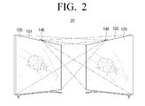
- FIG. 2 is a view illustrating the configuration of a communication system according to another exemplary embodiment.
- the communication system may include a first display device 101 and a second display device 102 as illustrated in FIG. 2 .
- the first and second display devices 101 and 102 may each include an image acquirer 140 including an image sensor 141 provided at predetermined positions (e.g., upper portions of front surfaces).
- the first and second display devices 101 and 102 may be angled toward each other at a predetermined angle.
- the first and second display devices 101 and 102 may face each other so that a camera included in the first display device 101 can acquire an image of the second display device 102, and vice-versa.
- the predetermined angle may be equal to or larger than 0o and equal to or smaller than 180o.
- the first and second display devices 101 and 102 may be TVs that display broadcasting images, smart TVs providing applications, or monitors connected to computer main bodies.
- the communication system includes devices that can be connected to communicate with each other.
- one of the first and second display devices 101 and 102 may operate as a host, and the other thereof may operate as a client.
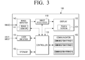
- FIG. 3 is a block diagram illustrating a configuration of an electronic device 100 according to an exemplary embodiment, and the configuration of the electronic device 100 illustrated in FIG. 3 can be applied to one or more of the first and second display devices 101 and 102 and the mobile device 103 of FIGS. 1 and 2 .
- the electronic device 100 may include an image processor 110 that processes n image signal received from an external source, a display 120 that displays the image signal processed by the image processor 110 as an image, a user inputter 130 that receives a user's input, an image acquirer 140 that acquires an image, a storage 150 in which various kinds of data are stored, a communicator 160 that performs wired and/or wireless communication with one or more external devices, and a controller 170 that controls the electronic device 100.
- an image processor 110 that processes n image signal received from an external source
- a display 120 that displays the image signal processed by the image processor 110 as an image
- a user inputter 130 that receives a user's input
- an image acquirer 140 that acquires an image
- a storage 150 in which various kinds of data are stored
- a communicator 160 that performs wired and/or wireless communication with one or more external devices
- a controller 170 that controls the electronic device 100.
- the image processor 110 may perform various preset image processes with respect to the image signal.
- the image processor 110 may output the image signal that is processed by the processes to the display 120 to display the image on the display 120.
- the image processor 110 may include an image receiver (not illustrated) that receives the image signal from an external source.
- the image processor 110 may be implemented in any of various manners to correspond to the standard of the received image signal or implementation type of the electronic device 100.
- the image processor 110 may wirelessly receive a radio frequency (RF) signal that is transmitted from a broadcasting station (not illustrated) or may receive, by wire, an image signal according to composite video, component video, super video, Syndicat des Constructeurs d'Appareils Radiorecepteurs et Téléviseurs (SCART), or high definition multimedia interface (HDMI) standards.
- RF radio frequency
- SCART Syndicat des Constructeurs d'Appareils Radiorecepteurs et Téléviseurs
- HDMI high definition multimedia interface
- the image signal may be input from an external device, and for example, the image signal may be input from an external device, such as a personal computer (PC), an audio/visual (AV) device, a smart phone, or a smart pad.
- the image signal may comprise data that is received through a network such as the Internet.
- the electronic device 100 may perform network communication through the communicator 160.
- the image signal may comprise data that is stored in a nonvolatile storage 150, such as a flash memory or a hard disk.
- the storage 150 may be provided within the electronic device 100 or externally, and in the case in which the storage 150 is provided externally, the storage 150 may further include a connector (not illustrated) to which the storage 150 is connected.
- the kind of image processes performed by the image processor 110 is not limited, and may include, for example, at least one of decoding that corresponds to various image formats, deinterleaving, frame refresh rate conversion, scaling, noise reduction for improving the image quality, detail enhancement, and line scanning.
- the image processor may be implemented by a group of an individual configuration that can independently perform respective processes or by a system-on-chip (SoC) that integrates various functions.
- SoC system-on-chip
- the display 120 displays an image based on the image signal processed by the image processor 110.
- the implementation method of the display 1120 is not limited, and may be implemented by, for example, any of various display types of displays including liquid crystal displays, plasma displays, light-emitting diode (LED) displays, organic light-emitting diode (OLED) displays, surface-conduction electron-emitter displays, carbon nano-tube displays, and nano-crystal displays.
- the display 120 may additionally include an additional configuration according the implementation type.
- the display 120 may include a liquid crystal display panel (not illustrated), a backlight unit (not illustrated) that supplies light to the liquid crystal display panel, and a panel driving board (not illustrated) that drives the panel (not illustrated).
- the display 120 may include a touch screen 121 that receives a user's touch input.
- the touch screen 121 may be, for example, a resistive type, a capacitive type, an infrared type, or an acoustic wave type.
- the touch screen 121 may display objects (e.g., menu, text, image, video, figure, icon, and shortcut icon) that include menu items of the display device 100.
- objects e.g., menu, text, image, video, figure, icon, and shortcut icon
- a user may touch an object displayed on the touch screen 121 using a user's body (e.g., finger) or a separate pointing device, such as stylus, to make a user input.
- the touch screen 121 may provide, to a user, a graphic user interface (GUI) that corresponds to any of various services (e.g., call, data transmission, broadcasting, photographing, moving image, and application).
- GUI graphic user interface
- the touch screen 121 may transmit, to the controller 170, an analog signal that corresponds to a single touch or multi-touch input through the GUI.
- the touch is not limited to a contact between the touch screen 121 and the user's body or a touchable pointing device, but further includes non-contact (e.g., hovering at which a detectable gap between the touch screen 121 and the user's body or the pointing device is equal to or smaller than 30 mm). It could be easily understood to those of ordinary skill in the art that the non-contact gap that can be detected on the touch screen 121 may be changed depending on the performance or structure of the electronic device 100.
- non-contact e.g., hovering at which a detectable gap between the touch screen 121 and the user's body or the pointing device is equal to or smaller than 30 mm.
- the touch input may include at least one of drag, flick, drag and drop, tap, and long tap.
- Communication interface information that is supported by the communicator 160 may be displayed on the display 120.
- the controller 170 may request the communication interface information from the communicator 160 that is stored in the storage 150 and may control the display 120 to display the communication interface information.
- the user inputter 130 may transfer any of various preset control commands or unlimited information to the controller 170 through the user's operation and input.
- the user inputter 130 may include a keypad (or input panel) (not illustrated) including buttons, such as numeral keys and menu keys provided on a main body of the electronic device 100, a remote controller that generates command/data/information/signal that are preset to remotely control the TV to transmit the generated command/data/information/signal to the electronic device 100, and an input device, such as a keyboard or a mouse, that is separately spaced apart from the main body.
- a keypad or input panel
- buttons such as numeral keys and menu keys provided on a main body of the electronic device 100
- a remote controller that generates command/data/information/signal that are preset to remotely control the TV to transmit the generated command/data/information/signal to the electronic device 100
- an input device such as a keyboard or a mouse
- the input device is an external device that can perform wireless communications with the main body of the electronic device 100, and the wireless communications may include infrared communication, radio frequency (RF) communication, and wireless local area network (LAN).
- the input device may be operated by the user to transmit preset commands to the electronic device 100.
- the keypad may include one or more of a physical keypad formed on the front surface and/or the side surface of the electronic device 100, a virtual keypad displayed on the touch screen 121, and a physical keypad that can be wirelessly connected. It would be understood by those of ordinary skill in the art that the physical keypad that is formed on the front surface and/or the side surface of the electronic device 100 may be excluded depending on the performance or the structure of the electronic device 100.
- the user inputter 130 may further include a touch sensor (not illustrated) provided on a remote controller to sense a user's touch, and a motion sensor (not illustrated) sensing user's self-motion.
- a touch sensor not illustrated
- a motion sensor not illustrated
- the user inputter 130 may receive, from the user, a communication connection request for communication with the other device, and may include a dedicated button that is provided to correspond to the communication connection request for communication with the other device.
- the image acquirer 140 may be a camera that captures an external image.
- the camera may be installed at a predetermined position, e.g., an upper portion, of the electronic device 100, but the installation position thereof is not limited thereto. According to circumstances, the camera may be installed outside of the main body, separated from the main body of the electronic device 100.
- the image acquirer 140 may include a lens (not illustrated), which transmits an image, and an image sensor 141 that senses the image transmitted by the lens.
- the image sensor 141 may be implemented by a charge-coupled device/complementary metal-oxide-semiconductor (CCD/CMOS) image sensor.
- CCD/CMOS charge-coupled device/complementary metal-oxide-semiconductor
- the image acquirer 140 may include at least one of a first camera on a front surface and a second camera on a rear surface, which capture a till image or a moving image under the control of the controller 170.
- the image acquirer 140 may include one or both of the first camera and the second camera.
- One or more of the first camera and the second camera may further include an auxiliary light source (e.g., a flash) that provides light required for photographing.
- the image acquirer 140 may read communication interface information that is supported by the other device through capturing of an image that is displayed on the display of the other device.
- the image input through the image acquirer 140 may be processed by the image processor 110.
- the controller 170 may extract the communication interface information of the other device, to be described later, from the image processed by the image processor 110.
- the controller 170 may establish a communication connection with the other device using the extracted communication interface information.
- unlimited data may be stored under the control of the controller 170.
- the storage 150 may include one or more of a nonvolatile memory, a volatile memory, a flash memory, a hard disk drive (HDD), or a solid state drive (SSD).
- the storage 150 may be accessed by the controller 170, and data read/write/correction/deletion/update processes may be performed by the controller 170.
- the data stored in the storage 150 may include an operating system for driving the electronic device 100, various applications that are executable on the operating system, image data, and additional data.
- GUIs graphic user interfaces
- various kinds of information including coordinate information for sensing a user's input on the touch screen 121, may be further stored.
- the controller 170 may identify the kind of the sensed touch input using the information pre-stored in the storage 150, and may calculate coordinate information (X and Y coordinates) that corresponds to the touch position to transfer the calculated coordinate information to the image processor 110. Further, an image that corresponds to the identified kind of touch input and the touch position may be displayed on the display 120 through the image processor 110.
- Communication interface information (or network interface information) that is supported by the communicator 160 may be further stored in the storage 150.
- the storage 150 may be implemented so that the communication interface information supported by the communicator 160 is pre-stored therein, or usable communication interfaces are inquired or searched in response to a user's connection request between devices and information that corresponds to the result of the inquiry is stored therein.
- the term “storage” may refer to a ROM (not illustrated), a RAM (not illustrated), which may be provided in the storage 150 or the controller 170, or a memory card (not illustrated) (e.g., micro secure digital (SD) card, or memory stick) which is mounted in the electronic device 100.
- ROM read only memory
- RAM random access memory
- memory card e.g., micro secure digital (SD) card, or memory stick
- the communicator 160 may perform communication with the other device.
- the communicator 160 may support at least one of communication interfaces 1 to N of Wi-Fi, Bluetooth, RF, Zigbee, wireless LAN, infrared communication, ultra wideband (UWB), and near field communication (NFC).
- the communicator 160 may further include a mobile communicator (not illustrated).
- the mobile communicator may transmit/receive wireless signals for voice call, video call, small message service (SMS), multimedia message service (MMS), and data communication with a portable phone, a smart phone, or a tablet, which has a phone number that is connectable to the electronic device 100.
- the communicator 160 may further include at least one wired communication interface.
- the communicator 160 may be built in the main body of the electronic device 100 or may be implemented in the form of a dongle or module to be detachably attached to a connector (not illustrated) of the electronic device 100.
- the controller 170 may perform a control operation with respect to various constituent elements of the electronic device 100.
- the controller 170 may control the whole operation of the electronic device 100 in a manner that the controller 170 performs proceeding of an image process that is performed by the image processor 110, controls an operation that corresponds to a command from the user inputter 130, senses of an operation position that corresponds to a user's touch on the touch screen 121 and sets a virtual point (X and Y coordinates) that corresponds to the user's touch, and an operation that corresponds to the user's touch.
- the controller 170 may be software coupled to a CPU.
- the controller 170 may control the whole operation of the electronic device 100 and signal flow between the internal constituent elements 110 to 160 of the electronic device 100, and perform a function of processing data.
- the controller 170 may control power supply from a power supply (not illustrated) to the internal constituent elements 110 to 160. Further, if a user's input is performed, or if conditions which have been set and stored are satisfied, the controller 170 may execute the operating system (OS) and various applications stored in the storage 150.
- OS operating system
- the controller 170 of the electronic device 100 may control the display 120 to display the communication interface information supported by the communicator 160 in response to the user's operation for communication connection with the other device.
- the communication interface information that is supported by the communicator 160 may be pre-stored in the storage 150 and may be displayed on the display 120 in any various formats, such as a text, a quick response (QR) code, and a barcode.
- the controller 170 may activate the image acquirer 140 and may receive the communication interface information of the other device that is sensed through the image sensor 141 in response to the user's operation for the communication connection with the other device. Further, the controller 170 may analyze the input communication interface information of the other device, compare the analyzed communication interface information of the other device with communication interface information supported by the corresponding device 100, determine the communication interface to be used for the communication connection, and set the communication connection with the other device based on the determined communication interface.
- the controller 170 may set the communication connection through the communication interface that is commonly supported by the electronic device 100 and the other device. If a plurality of communication interfaces are commonly supported by the two devices, the controller 170 may select an optimum interface, and for example, may select any one of the communication interfaces as the optimum communication interface according to at least one of a system environment, a preset priority, and user's setting.
- any one of the plurality of electronic devices 100 of the communication system may operate as a host, and the other thereof may operate as a client.
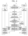
- FIG. 4 is a flowchart illustrating a connection control method of a communication system of FIG. 1 according to an exemplary embodiment.
- a mobile device 103 may receive a request for image quality matching between first and second display devices 101 and 102 from a user (S401).
- the user may execute an application for image quality matching through operation of a user inputter 130 or a touch screen 121 of the mobile device 103, and may request matching of image qualities between the first and second display devices 101 and 102 using a menu that is provided by an application.
- the controller 170 of the mobile device 103 may activate the image acquirer 140, i.e., camera, of the mobile device 103 (S403).
- the display 120 of the first display device 101 may display a first image (S411)
- the display 120 of the second display device 102 may display a second image (S431).
- the first image and the second image may be the same image.
- the first image and the second image may be the same image that is provided from the same source.
- the image acquirer 140 of the mobile device 103 may acquire the first image that is displayed on the first display device 101 and the second image that is displayed on the second display device 102 (S405). Acquiring of the first image and the second image through the image acquirer 140 of the mobile device 101 may include capturing and storing of the first image and the second image in the storage 150 of the mobile device 103 through the user's operation, or temporarily storing of the first image and the second image input through the image acquirer 140 and displaying of the stored images on the display 120 of the mobile device 103 even if there is not user's capturing operation.
- the controller 170 of the mobile device 103 may compare the first image and the second image with each other (S407). If it is determined that a difference in image quality between the first image and the second image is equal to or lower than a predetermined value as the result of the comparison (S408), the controller 170 of the mobile device 103 may end the image quality correction process of the first display device 101 or the second display device 102 (S411). In contrast, if the difference in image quality between the first image and the second image is higher than the predetermined value (S408), the controller 170 of the mobile device 103 may set the image quality correction value of the first display device 101 or the second display device 102 (S409).
- the controller 170 of the mobile device 103 may extract a region of the display 120 of the first display device 101 from the first image, and may extract a region of the display 120 of the second display device 102 from the second image.
- the extraction method of the regions of the displays 120 of the first and second display devices 101 and 102 may be determined in a manner that the controller 170 of the mobile device 103 recognizes frames of the first and second display devices 101 and 102 from the first image and the second image and determines central region of the frame as the region of the display 120, or the controller 170 recognizes the brightnesses of the first image and the second image and determines a relatively bright region as the region of the display 120.
- the first image comprises the portion of the display 120 of the first display device 101
- the second image comprises the portion of the display 120 of the second display region 102.
- the controller 170 of the mobile device 103 may acquire pixel values in predetermined positions of the regions of the first image and the second image.
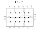
- FIG. 7 is a view illustrating positions of pixel values acquired from a first image and a second image through a mobile device 103.
- the controller 170 of the mobile device 103 may acquire the pixel values in positions in which the first image and the second image are respectively divided into equal parts at predetermined intervals in horizontal and vertical directions. The divided parts in the horizontal and vertical directions cross each other.
- the controller 170 of the mobile device 103 may acquire pixel values 701 to 715 in positions in which the first image and the second image are respectively divided into three and four equal parts in the horizontal and vertical directions, respectively, and the divided parts in the horizontal and vertical directions cross each other.
- the portion of the display of each of the first and second display devices is divided into a 3 x 4 matrix, and the pixel values are values at intersections of the sections of the matrix.
- the controller 170 of the mobile device 103 may obtain average values of red (R), green (G), and blue (B) colors of the pixel values acquired from the first image and average values of R, G, and B colors of the pixel values acquired from the second image.
- the average value of the R, G, and B colors may be any one of "0" to "255” according to an RGB color code.
- the controller 170 of the mobile device 103 may calculate a difference between average values through comparison of the average value of the R, G, and B colors acquired from the first image with the average value of the R, G, and B colors acquired from the second image.
- the controller 170 of the mobile device 103 compares the average values of the R, G, and B colors, and the controller 170 of the mobile device 103 may use a median of the R, G, and B colors or a mode of the R, G, and B colors.
- the controller 170 of the mobile device 103 may determine the image quality correction value of the first display device 101 or the second display device 102 based on the difference in average value between the R, G, and B colors of the first image and the R, G, and B colors of the second image. It is described herein that the controller 170 of the mobile device 103 determines the image quality correction value based on the R, G, and B color values of the pixel values of the first image.
- the image quality correction value can be determined using any of various kinds of pixel information, such as brightness and luminance.
- FIGS. 8A to 8D are diagrams illustrating tables including image quality correction values of one of a first display device 101 and a second display device 102.
- FIG. 8A shows a table 810 in which image quality correction values of the first display device 101 are shown.
- the table 810 includes an R color average value difference field 811 and an R color image quality correction value field 812 for the first display device 101.
- the field 811 indicates a value obtained by subtracting the average value of the R color of the second image from the average value of the R color of the first image
- the field 812 indicates the image quality correction value of the R color of the first display device 101.
- image quality correction values of R color of the first display device 101 are, for example, in the range of "0" to "100", and an initial offset value of R color is "50".
- the range of the image quality correction values of R, G, and B colors may be equal to the range that can be adjusted by a user using a menu key provided on the main body of the electronic device 100 or a bottom of a remote controller.
- the image quality correction value field 812 that corresponds to the R color average value difference field 811 may have different values depending on the average value difference of the R color.
- the image quality correction value of the R color of the first display device 101 may be determined as "+20". Further, referring to a field 815 of the table 810, if the value that is obtained by subtracting the average value of the R color of the second image from the average value of the R color of the first image is larger than "-50" and smaller than "-40", the image quality correction value of the R color of the first display device 101 may be determined as "+16".
- the image quality correction value of the R color of the first display device 101 may be determined according to the difference between average values of the R colors.
- the difference between the average values of R colors of the first image and the second image is larger than "-10" and is smaller than "+10"
- the image quality correction of the R color of the first display device 101 may be ended.
- FIG. 8B shows a table 830 in which image quality correction values of the first display device 101 and the second display device 102 are shown.
- the table 830 includes an R color average value difference field 831, an R color image quality correction value field 832 of the first display device 101, and an R color image quality correction value field 833 of the second display device 102.
- the field 831 indicates a value obtained by subtracting the average value of the R color of the second image from the average value of the R color of the first image
- the field 832 indicates the image quality correction value of the R color of the first display device 101.
- the field 833 indicates the image quality correction value of the R color of the second display device 102.
- image quality correction values of R colors of the first and second display device 101 and 102 are, for example, in the range of "0" to "100", and an initial offset value of R color is "50".
- the image quality correction value fields 832 and 833 that correspond to the R color average value difference field 831 may have different values depending on the average value difference of the R color.
- the image quality correction value of the R color of the first display device 101 may be determined as "+10"
- the image quality correction value of the R color of the second display device 102 may be determined as "-10".
- the image quality correction value of the R color of the first display device 101 may be determined as "+8” and the image quality correction value of the R color of the second display device 102 may be determined as "-8".
- the image quality correction values of the R colors of the first and second display devices 101 and 102 may be determined according to the difference between average values of the R colors.
- the image quality correction of the R colors of the first and second display devices 101 and 102 may be ended.
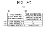
- FIG. 8C shows a table 850 in which image quality correction values of the first display device 101 are shown.
- the table 850 includes an R color average value difference field 851 and an R color image quality correction value field 852 of the first display device 101.
- the field 851 indicates a value obtained by subtracting the average value of the R color of the second image from the average value of the R color of the first image
- the field 852 indicates the image quality correction value of the R color of the first display device 101.
- image quality correction values of R color of the first display device 101 are, for example, in the range of "0" to "100", and an initial offset value of R color is "50".
- the image quality correction value of the R color of the first display device 101 may be determined as "+4". Further, referring to a field 855 of the table 850, if the value that is obtained by subtracting the average value of the R color of the second image from the average value of the R color of the first image is equal to or larger than "+10", the image quality correction value of the R color of the first display device 101 may be determined as "+4".
- the image quality correction of the R color of the first display device 101 may be ended.
- FIG. 8D shows a table 870 in which image quality correction values of the first and second display devices 101 and 102 are shown.
- the table 870 includes an R color average value difference field 871, an R color image quality correction value field 872 of the first display device 101, and an R color image quality correction value field 873 of the second display device 102.
- the field 871 indicates a value obtained by subtracting the average value of the R color of the second image from the average value of the R color of the first image
- the field 872 indicates the image quality correction value of the R color of the first display device 101.
- the field 873 indicates the image quality correction value of the R color of the second display device 102.
- image quality correction values of R colors of the first and second display device 101 and 102 are, for example, in the range of "0" to "100", and an initial offset value of R color is "50".
- the image quality correction value fields 872 and 873 that correspond to the R color average value difference field 871 may have different values depending on the average value difference of the R color.
- the image quality correction value of the R color of the first display device 101 may be determined as "+2"
- the image quality correction value of the R color of the second display device 102 may be determined as "-2".
- the image quality correction value of the R color of the first display device 101 may be determined as "+2" and the image quality correction value of the R color of the second display device 102 may be determined as "+2".
- the difference between the average values of R colors of the first image and the second image is larger than "-10" and is smaller than "+10"
- the image quality correction of the R colors of the first and second display devices 101 and 102 may be ended.
- the communicator 160 of the mobile device 103 may transmit the image quality correction value of the first display device 101 to the first display device 101 (S410). Further, the communicator 160 of the mobile device 103 may transmit the image quality correction value of the second display device 102 to the second display device 102 (S410). Further, the communicator 160 of the mobile device 103 may transmit the image quality correction value of the first display device 101 to the first display device 101, and may transmit the image quality correction value of the second display device 102 to the second display device 102 (S410).
- the communicator 160 of the first display device 101 may receive the image quality correction value of the first display device 101 (S422).
- the controller 170 of the first display device 101 may adjust the image quality of the display 120 of the first display device 101 through applying of the received image quality correction value (S423).
- the controller 170 of the first display device 101 may display the first image to which the image quality correction value has been applied through the display 120 of the first display device 101 (S421).
- the communicator 160 of the second display device 102 may receive the image quality correction value of the second display device 102 (S432).
- the controller 170 of the second display device 102 may adjust the image quality of the display 120 of the second display device 102 through applying of the received image quality correction value (S433).
- the controller 170 of the second display device 102 may display the second image to which the image quality correction value has been applied through the display 120 of the second display device 102 (S431).
- both the first display device 101 and the second display device 102 may receive the image quality correction values (S422 and S432).
- the controller 170 of the first display device 101 and the controller 170 of the second display device 102 may adjust the image qualities of the displays 120 of the first display device 101 and the second display device 102 through applying of the received image quality correction values (S423 and S433).
- the first image to which the image quality correction value has been applied may be displayed through the display 120 of the first display device 101 (S421)
- the second image to which the image quality correction value has been applied may be displayed through the display 120 of the second display device 102 (S431).
- the camera of the mobile device 103 may acquire again the first image and the second image to which the image quality correction values have been applied (S405). Further, the controller 170 of the mobile device 103 may repeat S405 to S410 until the difference between the first image and the second image to which the image quality correction values have been applied becomes equal to or smaller than a predetermined value.
- the controller 170 of the mobile device 103 may repeat S405 to S410 so that the image quality of the first image that is displayed on the first display device 101 becomes equal to or similar to the image quality of the second image that is displayed on the second display device 102.
- a case where the image quality of the first image is equal to the image quality of the second image may mean a case where an average value of the acquired pixel values of the first image to which the image quality correction value has been applied is equal to an average value of the acquired pixel values of the second image to which the image quality correction value has been applied.
- a case in which the image quality of the first image is similar to the image quality of the second image may means a case where the difference between the average value of the acquired pixel values of the first image to which the image quality correction value has been applied and the average value of the acquired pixel values of the second image to which the image quality correction value has been applied is equal to or smaller than a predetermined value.
- the controller 170 of the mobile device 103 may end the image quality correction of the first display device 101 and the second display device 102.
- the controller 170 of the mobile device 103 may notify a user, through the display, that the image qualities of the images of the first display device 101 and the second display device 102 are matched.
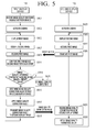
- FIG. 5 is a flowchart illustrating a connection control method of a communication system of FIG. 2 according to an exemplary embodiment.
- a first display device 101 may receive, from a user, a request for image quality matching between first and second display devices 101 and 102 (S501).
- the user may execute an OSD menu of the first display device 101 through operation of a user inputter 130 of the first display device 101, and may request matching of image qualities between the first and second display devices 101 and 102 through the OSD menu.
- the controller 170 of the first display device 101 may activate the image acquirer 140, i.e., camera, of the first display device 101 (S503). Further, the controller 170 of the first display device 101 may provide a signal, to the second display device 102, for requesting activation of the image acquirer 140, i.e., the camera, of the second display device 102. In response to the camera activation signal from the first display device 101, the controller 170 of the second display device 102 may activate the image acquirer 140, i.e., the camera, of the second display device 102 (S523).
- the first display device 101 may display the first image through the display 120 of the first display device 101 (S505), and the second display device 102 may display the second image through the display 120 of the second display device 102 (S525).
- the first and second display devices 101 and 102 might display the first image and the second image before the cameras of the first and second display devices 101 and 102 are activated.
- the first image and the second image may be the same image.
- the first image and the second image may be the same image provided from the same source.
- the image acquirer 140 of the first display device 101 may acquire the second image that is displayed on the second display device 102 (S507), and the image acquirer 140 of the second display device 102 may acquire the first image that is displayed on the first display device 102 (S527).
- the communicator 160 of the second display device 102 may transmit the acquired first image to the first display device (S529).
- the communicator 160 of the first display device 101 may receive the first image (S509).
- the first display device 101 may compare the received first image and the acquired second image (S507) with each other (S511). If it is determined that a difference in image quality between the first image and the second image is equal to or lower than a predetermined value as the result of the comparison (S513), the controller 170 of the first display device 101 may end the image quality correction process of the first display device 101 or the second display device 102 (S519). In contrast, if the difference in image quality between the first image and the second image is higher than the predetermined value (S513), the controller 170 of the first display device 101 may determine the image quality correction value of one or both of the first display device 101 and the second display device 102 (S515).
- the controller 170 of the first display device 101 may acquire pixel values from the first image and the second image as described above, and may determine the image quality correction values of one or both of the first display device 101 and the second display device 102 with reference to a table depending on the difference between average values of the pixel values of the first image and the second image (S515). If the pixel values are acquired from the first image and the second image, the controller 170 of the first display device 101 may acquire the pixel values in consideration of the resolution of the first image and the second image.
- the controller 170 of the first display device 101 may acquire the pixel values of the second image of which the number is larger than the number of pixel values of the second image when acquiring the pixel values in positions in which the first image and the second image are respectively divided into equal parts at a predetermined interval in horizontal and vertical directions and the divided parts in the horizontal and vertical directions cross each other. Further, the controller 170 of the first display device may compare average values of the pixels of the first image and the second image with each other.
- the controller 170 of the first display device 101 may adjust the image quality of the display 120 of the first display device 101 through application of the determined image quality correction value (S517). As the result of the image quality adjustment, the controller 170 of the first display device 101 may display the first image to which the image quality correction value has been applied through the display 120 of the first display device 101 (S505). If the image quality correction value of the second display device 102 is determined (S515), the communicator 160 of the first display device 101 may transmit the image quality correction value of the second display device 102 to the second display device 102 (S518).
- the communicator 160 of the second display device 102 may receive the image quality correction value of the second display device 102 (S531).
- the controller 170 of the second display device 102 may adjust the image quality of the display 120 of the second display device 102 through application of the received image quality correction value (S533).
- the controller 170 of the second display device 102 may display the second image to which the image quality correction value has been applied through the display 120 of the second display device 102 (S525).
- the camera of the first display device 101 may again acquire the second image to which the image quality correction value has been applied, and the communicator 160 of the first display device 101 may receive again the first image to which the image quality correction value has been applied from the second display device 102. Further, the controller 170 of the first display device 101 may repeat S505 to S518 until the difference between the first image and the second image to which the image quality correction values have been applied becomes equal to or smaller than a predetermined value.
- the controller 170 of the first display device 101 may repeat S505 to S518 so that the image quality of the first image that is displayed on the first display device 101 becomes equal to or similar to the image quality of the second image that is displayed on the second display device 102.
- the controller 170 of the first display device 101 may end the image quality correction of the first display device 101 and the second display device 102.
- the controller 170 of the first display device 101 may notify a user, through the display 120, that the image qualities of the images of the first display device 101 and the second display device 102 are matched.
- FIG. 6 is a flowchart illustrating a connection control method of a communication system of FIG. 1 according to another exemplary embodiment.
- a first display device 101 may receive, from a user, a request for image quality matching between first and second display devices 101 and 102 (S601).
- the user may execute an OSD menu of the first display device 101 through operation of a user inputter 130 of the first display device 101, and, through the OSD menu, the user may request matching of image qualities between the first and second display devices 101 and 102.
- the controller 170 of the first display device 101 may provide, to the mobile device 103, a signal for requesting activation of the image acquirer 140, i.e., the camera, of the mobile device 103.
- the controller 170 of the mobile device 103 may activate the image acquirer 140, i.e., the camera, of the mobile device 103 (S621).
- the first display device 101 may display the first image through the display 120 of the first display device 101 (S603)
- the second display device 102 may display the second image through the display 120 of the second display device 102 (S643).
- the image acquirer 140 of the mobile device 103 may acquire the first image that is displayed on the first display device 101 and the second image that is displayed on the second display device 102 (S623). Further, the image acquirer 140 of the mobile device 103 may transmit the acquired first and second images to the first display device 103 (S625). The first display device 101 may receive the transmitted first and second images (S606).
- the first display device 101 may compare the received first and second images with each other (S608). If it is determined that a difference in image quality between the first image and the second image is equal to or lower than a predetermined value as the result of the comparison (S610), the controller 170 of the first display device 101 may end the image quality correction process of the first display device 101 or the second display device 102 (S618). In contrast, if the difference in image quality between the first image and the second image is higher than the predetermined value (S610), the controller 170 of the first display device 101 may determine the image quality correction value of the first display device 101 or the second display device 102 (S612).
- the controller 170 of the first display device 101 may acquire pixel values from the first image and the second image as described above, and may determine the image quality correction values of the first display device 101 and the second display device 102 with reference to a table depending on the difference between average values of the pixel values of the first image and the second image (S612).
- the controller 170 of the first display device 101 may adjust the image quality of the display 120 of the first display device 101 through application of the determined image quality correction value (S614). As the result of the image quality adjustment, the controller 170 of the first display device 101 may display the first image to which the image quality correction value has been applied through the display 120 of the first display device 101 (S603). If the image quality correction value of the second display device 102 is determined (S612), the communicator 160 of the first display device 101 may transmit the image quality correction value of the second display device 102 to the mobile device 103 or the second display device 102 (S616).
- the controller 170 of the mobile device 103 may determine that the image quality matching process is not ended, and may continuously activate the image acquirer 140, i.e., the camera, of the mobile device 103. Further, the communicator 160 of the mobile device 103 may transmit again the received image quality correction value to the second display device 102 (S628).
- the communicator 160 of the second display device 102 may receive the image quality correction value of the second display device 102 (S645).
- the controller 170 of the second display device 102 may adjust the image quality of the display 120 of the second display device 102 through application of the received image quality correction value (S647).
- the controller 170 of the second display device 102 may display the second image to which the image quality correction value has been applied through the display 120 of the second display device 102 (S643).
- the camera of the mobile device 103 may again acquire the first image and the second image, and may transmit the acquired first and second images to the first display device 101.
- the communicator 160 of the first display device 101 may again receive the first image and the second image from the mobile device 103.
- the controller 170 of the first display device 101 may repeat S603 to S616 until the difference between the first image and the second image to which the image quality correction values have been applied becomes equal to or smaller than a predetermined value.
- the controller 170 of the first display device 101 may repeat S603 to S616 so that the image quality of the first image that is displayed on the first display device 101 becomes equal to or similar to the image quality of the second image that is displayed on the second display device 102.
- the controller 170 of the first display device 101 may end the image quality correction of the first display device 101 and the second display device 102.
- the controller 170 of the first display device 101 may notify a user, through the display 120, that the image qualities of the images of the first display device 101 and the second display device 102 are matched.
- the above-described exemplary embodiments may be realized in the form of hardware, software, or a combination thereof.
- the software may be stored, regardless of whether the software can be deleted or re-written, for example, in a volatile or nonvolatile storage device, such as a ROM, in a memory, such as a RAM, a memory chip, a device, or an integrated circuit, or in a recording medium that can be optically or magnetically recordable and readable through a machine (e.g., computer), such as a CD, a DVD, a magnetic disc, or a magnetic tape.
- a volatile or nonvolatile storage device such as a ROM
- a memory such as a RAM, a memory chip, a device, or an integrated circuit
- a recording medium that can be optically or magnetically recordable and readable through a machine (e.g., computer), such as a CD, a DVD, a magnetic disc, or a magnetic tape.
- the image quality matching method among the plurality of display devices may be implemented by a computer or a portable terminal, which includes a controller and a memory, and the memory may be an example of a machine-readable recording medium that is suitable to store a program or programs including instructions for implementing the described embodiments. Accordingly, the present disclosure includes a program including codes for implementing the device and method described in the claims and a machine (computer)-readable recording medium storing such a program.
- a user may selectively limit the operation according to the embodiments to a portable terminal or extend the operation to be in association with a server through a network.
Landscapes
- Engineering & Computer Science (AREA)
- Physics & Mathematics (AREA)
- Theoretical Computer Science (AREA)
- General Physics & Mathematics (AREA)
- Multimedia (AREA)
- Signal Processing (AREA)
- Spectroscopy & Molecular Physics (AREA)
- Computer Hardware Design (AREA)
- Human Computer Interaction (AREA)
- General Engineering & Computer Science (AREA)
- Controls And Circuits For Display Device (AREA)
- Two-Way Televisions, Distribution Of Moving Picture Or The Like (AREA)
- Computer Graphics (AREA)
- Telephone Function (AREA)
Applications Claiming Priority (1)
| Application Number | Priority Date | Filing Date | Title |
|---|---|---|---|
| KR1020140021511A KR102170101B1 (ko) | 2014-02-24 | 2014-02-24 | 디스플레이 장치, 모바일 장치, 이를 포함하는 시스템 및 그 화질 매칭 방법 |
Publications (3)
| Publication Number | Publication Date |
|---|---|
| EP2953341A2 true EP2953341A2 (fr) | 2015-12-09 |
| EP2953341A3 EP2953341A3 (fr) | 2016-03-16 |
| EP2953341B1 EP2953341B1 (fr) | 2022-08-31 |
Family
ID=52464161
Family Applications (1)
| Application Number | Title | Priority Date | Filing Date |
|---|---|---|---|
| EP15153067.2A Active EP2953341B1 (fr) | 2014-02-24 | 2015-01-29 | Dispositif mobile, système comprenant celui-ci et son procédé de mise en correspondance de qualité d'image |
Country Status (5)
| Country | Link |
|---|---|
| US (1) | US9799251B2 (fr) |
| EP (1) | EP2953341B1 (fr) |
| JP (1) | JP6523706B2 (fr) |
| KR (1) | KR102170101B1 (fr) |
| CN (1) | CN104869462B (fr) |
Families Citing this family (13)
| Publication number | Priority date | Publication date | Assignee | Title |
|---|---|---|---|---|
| US20150205396A1 (en) * | 2012-10-19 | 2015-07-23 | Mitsubishi Electric Corporation | Information processing device, information terminal, information processing system and calibration method |
| CN105554562A (zh) * | 2015-12-10 | 2016-05-04 | 天脉聚源(北京)传媒科技有限公司 | 一种图像显示方法及装置 |
| CN105679263B (zh) * | 2016-02-01 | 2018-07-20 | 深圳市华星光电技术有限公司 | 用于拼接显示装置显示颜色的方法及系统 |
| US20170289517A1 (en) * | 2016-04-01 | 2017-10-05 | Htc Corporation | Method and display system for adjusting output image of display |
| JP6873648B2 (ja) * | 2016-10-04 | 2021-05-19 | キヤノン株式会社 | 電子機器、表示装置、及び情報出力方法 |
| KR102545813B1 (ko) * | 2016-12-30 | 2023-06-21 | 삼성전자주식회사 | 디스플레이 장치 및 디스플레이 방법 |
| KR102442449B1 (ko) * | 2017-09-01 | 2022-09-14 | 삼성전자주식회사 | 영상 처리 장치, 영상 처리 방법 및 컴퓨터 판독가능 기록 매체 |
| US10467774B2 (en) * | 2017-11-06 | 2019-11-05 | Qualcomm Incorporated | Memory address flipping to determine data content integrity in GPU sub-system |
| CN108333801B (zh) * | 2018-01-15 | 2021-09-10 | 武汉精测电子集团股份有限公司 | 液晶模组色度值采集系统及方法 |
| JP2019149767A (ja) * | 2018-02-28 | 2019-09-05 | パナソニック液晶ディスプレイ株式会社 | 表示装置用校正システム、表示装置、撮影装置、サーバ装置、及び、表示装置の校正方法 |
| KR102618900B1 (ko) * | 2019-01-08 | 2023-12-29 | 삼성전자주식회사 | 디스플레이 장치 및 그 제어 방법 |
| KR102436020B1 (ko) * | 2019-01-31 | 2022-08-24 | 삼성전자주식회사 | 전자 장치 및 그 제어 방법 |
| US11955074B2 (en) | 2021-02-15 | 2024-04-09 | Samsung Electronics Co., Ltd. | Electronic device and method for calibrating image data in electronic device |
Family Cites Families (24)
| Publication number | Priority date | Publication date | Assignee | Title |
|---|---|---|---|---|
| US20030156073A1 (en) * | 2002-02-20 | 2003-08-21 | Koninlijke Philips Electronics N.V. | Apparatus for adjusting proximate video monitors to output substantially identical video images and corresponding methods therefor |
| JP4027284B2 (ja) * | 2002-07-26 | 2007-12-26 | キヤノン株式会社 | 画像表示装置の製造方法 |
| JP2005159812A (ja) * | 2003-11-27 | 2005-06-16 | Matsushita Electric Ind Co Ltd | 映像表示装置、マルチディスプレイ装置および当該マルチディスプレイ装置における輝度調整方法 |
| JP4698155B2 (ja) * | 2004-03-04 | 2011-06-08 | Necディスプレイソリューションズ株式会社 | 表示装置の表示特性調整方法 |
| EP1875732B1 (fr) * | 2005-04-26 | 2016-12-28 | Imax Corporation | Systemes de projection electronique et procedes associes |
| WO2007029997A1 (fr) * | 2005-09-05 | 2007-03-15 | Continuum Science And Technologies Sdn Bhd | Systeme d'affichage utilisant des unites d'affichage multiples |
| US8777418B2 (en) * | 2006-01-26 | 2014-07-15 | Christie Digital Systems Usa, Inc. | Calibration of a super-resolution display |
| JP2007279643A (ja) * | 2006-04-12 | 2007-10-25 | Nec Engineering Ltd | Dlpプロジェクタにおける色補正方法 |
| US8248454B2 (en) * | 2007-11-14 | 2012-08-21 | Hewlett-Packard Development Company, L.P. | Video display calibration system and method |
| CN101483742A (zh) * | 2009-01-23 | 2009-07-15 | 华南理工大学 | 组合式大屏幕前向投影显示方法及控制装置 |
| KR20110041845A (ko) * | 2009-10-16 | 2011-04-22 | 엘지전자 주식회사 | 멀티 플라즈마 디스플레이 장치 |
| US8606004B2 (en) * | 2010-07-15 | 2013-12-10 | Mersive Technologies, Inc. | System and method for automatic color matching in a multi-display system using sensor feedback control |
| US8836796B2 (en) * | 2010-11-23 | 2014-09-16 | Dolby Laboratories Licensing Corporation | Method and system for display characterization or calibration using a camera device |
| JP2012134698A (ja) * | 2010-12-21 | 2012-07-12 | Samsung Yokohama Research Institute Co Ltd | 撮像装置及び画像出力方法 |
| JP6039203B2 (ja) * | 2011-05-23 | 2016-12-07 | キヤノン株式会社 | 画像出力装置、画像出力装置の制御方法、及び、プログラム |
| US8531474B2 (en) * | 2011-11-11 | 2013-09-10 | Sharp Laboratories Of America, Inc. | Methods, systems and apparatus for jointly calibrating multiple displays in a display ensemble |
| CN103167293B (zh) * | 2011-12-09 | 2015-07-22 | 夏普株式会社 | 显示系统 |
| CN102521838B (zh) * | 2011-12-19 | 2013-11-27 | 国家计算机网络与信息安全管理中心 | 一种图像匹配方法及系统 |
| GB2497936B (en) * | 2011-12-22 | 2015-04-08 | Canon Kk | Method and device for controlling a video projector in a video projection system comprising multiple video projectors |
| US9817305B2 (en) * | 2012-07-12 | 2017-11-14 | Cj Cgv Co., Ltd. | Image correction system and method for multi-projection |
| TW201424372A (zh) * | 2012-12-11 | 2014-06-16 | Hon Hai Prec Ind Co Ltd | 電視牆調整裝置及方法 |
| US8836797B1 (en) * | 2013-03-14 | 2014-09-16 | Radiant-Zemax Holdings, LLC | Methods and systems for measuring and correcting electronic visual displays |
| US20140292616A1 (en) * | 2013-03-28 | 2014-10-02 | Nvidia Corporation | Computer monitor equalization using handheld device |
| US9420145B2 (en) * | 2014-01-13 | 2016-08-16 | Marvell World Trade Ltd. | System and method for tone mapping of images |
-
2014
- 2014-02-24 KR KR1020140021511A patent/KR102170101B1/ko active IP Right Grant
-
2015
- 2015-01-29 EP EP15153067.2A patent/EP2953341B1/fr active Active
- 2015-02-19 JP JP2015030290A patent/JP6523706B2/ja not_active Expired - Fee Related
- 2015-02-19 US US14/625,850 patent/US9799251B2/en active Active
- 2015-02-25 CN CN201510087087.5A patent/CN104869462B/zh not_active Expired - Fee Related
Non-Patent Citations (1)
| Title |
|---|
| None |
Also Published As
| Publication number | Publication date |
|---|---|
| EP2953341A3 (fr) | 2016-03-16 |
| US20150242178A1 (en) | 2015-08-27 |
| EP2953341B1 (fr) | 2022-08-31 |
| JP6523706B2 (ja) | 2019-06-05 |
| KR102170101B1 (ko) | 2020-10-26 |
| US9799251B2 (en) | 2017-10-24 |
| CN104869462B (zh) | 2019-06-25 |
| JP2015159540A (ja) | 2015-09-03 |
| KR20150100123A (ko) | 2015-09-02 |
| CN104869462A (zh) | 2015-08-26 |
Similar Documents
| Publication | Publication Date | Title |
|---|---|---|
| EP2953341B1 (fr) | Dispositif mobile, système comprenant celui-ci et son procédé de mise en correspondance de qualité d'image | |
| KR102625830B1 (ko) | 디스플레이장치, 그 제어방법 및 기록매체 | |
| US10346120B2 (en) | Method of displaying image by using a plurality of display apparatuses and electronic apparatus controlling a plurality of display apparatuses | |
| US9661230B2 (en) | Image display apparatus and method of operating the image display apparatus | |
| TWI525439B (zh) | 顯示器及其多裝置畫面的操作方法 | |
| CN108886634B (zh) | 显示装置及操作显示装置的方法 | |
| KR20120051209A (ko) | 멀티미디어 장치의 디스플레이화면 제공 방법 및 그에 따른 멀티미디어 장치 | |
| US20150077357A1 (en) | Display apparatus and control method thereof | |
| EP2899986B1 (fr) | Appareil d'affichage, appareil mobile, système et procédé de commande de réglage pour la connexion de celui-ci | |
| US10609305B2 (en) | Electronic apparatus and operating method thereof | |
| KR102208893B1 (ko) | 디스플레이 장치 및 디스플레이 장치의 채널 맵 관리 방법 | |
| KR102508148B1 (ko) | 디지털 디바이스 및 그를 이용한 컬러 제어 시스템 및 방법 | |
| US20130194270A1 (en) | Remote Graphics Corresponding to Region | |
| KR102274542B1 (ko) | 디스플레이 장치 및 이의 화면을 제어하는 방법 | |
| US10432909B2 (en) | Digital signage system and data processing method in the same | |
| US11436965B2 (en) | Display device and control method of same | |
| KR20150028435A (ko) | 디스플레이 장치 및 그의 동작 방법 | |
| KR20150119701A (ko) | 메인 디스플레이장치, 서브 디스플레이장치, 이를 포함하는 다중 디스플레이 시스템 및 그 제어방법 | |
| KR20150074602A (ko) | 디스플레이 장치 및 그의 동작 방법 |
Legal Events
| Date | Code | Title | Description |
|---|---|---|---|
| PUAI | Public reference made under article 153(3) epc to a published international application that has entered the european phase |
Free format text: ORIGINAL CODE: 0009012 |
|
| AK | Designated contracting states |
Kind code of ref document: A2 Designated state(s): AL AT BE BG CH CY CZ DE DK EE ES FI FR GB GR HR HU IE IS IT LI LT LU LV MC MK MT NL NO PL PT RO RS SE SI SK SM TR |
|
| AX | Request for extension of the european patent |
Extension state: BA ME |
|
| PUAL | Search report despatched |
Free format text: ORIGINAL CODE: 0009013 |
|
| AK | Designated contracting states |
Kind code of ref document: A3 Designated state(s): AL AT BE BG CH CY CZ DE DK EE ES FI FR GB GR HR HU IE IS IT LI LT LU LV MC MK MT NL NO PL PT RO RS SE SI SK SM TR |
|
| AX | Request for extension of the european patent |
Extension state: BA ME |
|
| RIC1 | Information provided on ipc code assigned before grant |
Ipc: G09G 5/12 20060101ALI20160209BHEP Ipc: H04N 9/68 20060101ALI20160209BHEP Ipc: H04N 1/60 20060101AFI20160209BHEP Ipc: G01J 3/50 20060101ALI20160209BHEP Ipc: G06F 3/14 20060101ALI20160209BHEP |
|
| 17P | Request for examination filed |
Effective date: 20160608 |
|
| RBV | Designated contracting states (corrected) |
Designated state(s): AL AT BE BG CH CY CZ DE DK EE ES FI FR GB GR HR HU IE IS IT LI LT LU LV MC MK MT NL NO PL PT RO RS SE SI SK SM TR |
|
| STAA | Information on the status of an ep patent application or granted ep patent |
Free format text: STATUS: EXAMINATION IS IN PROGRESS |
|
| 17Q | First examination report despatched |
Effective date: 20190618 |
|
| STAA | Information on the status of an ep patent application or granted ep patent |
Free format text: STATUS: EXAMINATION IS IN PROGRESS |
|
| STAA | Information on the status of an ep patent application or granted ep patent |
Free format text: STATUS: EXAMINATION IS IN PROGRESS |
|
| GRAP | Despatch of communication of intention to grant a patent |
Free format text: ORIGINAL CODE: EPIDOSNIGR1 |
|
| STAA | Information on the status of an ep patent application or granted ep patent |
Free format text: STATUS: GRANT OF PATENT IS INTENDED |
|
| INTG | Intention to grant announced |
Effective date: 20220408 |
|
| GRAS | Grant fee paid |
Free format text: ORIGINAL CODE: EPIDOSNIGR3 |
|
| GRAA | (expected) grant |
Free format text: ORIGINAL CODE: 0009210 |
|
| STAA | Information on the status of an ep patent application or granted ep patent |
Free format text: STATUS: THE PATENT HAS BEEN GRANTED |
|
| AK | Designated contracting states |
Kind code of ref document: B1 Designated state(s): AL AT BE BG CH CY CZ DE DK EE ES FI FR GB GR HR HU IE IS IT LI LT LU LV MC MK MT NL NO PL PT RO RS SE SI SK SM TR |
|
| RAP3 | Party data changed (applicant data changed or rights of an application transferred) |
Owner name: SAMSUNG ELECTRONICS CO., LTD. |
|
| REG | Reference to a national code |
Ref country code: CH Ref legal event code: EP Ref country code: GB Ref legal event code: FG4D |
|
| REG | Reference to a national code |
Ref country code: AT Ref legal event code: REF Ref document number: 1516172 Country of ref document: AT Kind code of ref document: T Effective date: 20220915 Ref country code: DE Ref legal event code: R096 Ref document number: 602015080542 Country of ref document: DE |
|
| REG | Reference to a national code |
Ref country code: IE Ref legal event code: FG4D |
|
| REG | Reference to a national code |
Ref country code: LT Ref legal event code: MG9D |
|
| REG | Reference to a national code |
Ref country code: NL Ref legal event code: MP Effective date: 20220831 |
|
| PG25 | Lapsed in a contracting state [announced via postgrant information from national office to epo] |
Ref country code: SE Free format text: LAPSE BECAUSE OF FAILURE TO SUBMIT A TRANSLATION OF THE DESCRIPTION OR TO PAY THE FEE WITHIN THE PRESCRIBED TIME-LIMIT Effective date: 20220831 Ref country code: RS Free format text: LAPSE BECAUSE OF FAILURE TO SUBMIT A TRANSLATION OF THE DESCRIPTION OR TO PAY THE FEE WITHIN THE PRESCRIBED TIME-LIMIT Effective date: 20220831 Ref country code: NO Free format text: LAPSE BECAUSE OF FAILURE TO SUBMIT A TRANSLATION OF THE DESCRIPTION OR TO PAY THE FEE WITHIN THE PRESCRIBED TIME-LIMIT Effective date: 20221130 Ref country code: LV Free format text: LAPSE BECAUSE OF FAILURE TO SUBMIT A TRANSLATION OF THE DESCRIPTION OR TO PAY THE FEE WITHIN THE PRESCRIBED TIME-LIMIT Effective date: 20220831 Ref country code: LT Free format text: LAPSE BECAUSE OF FAILURE TO SUBMIT A TRANSLATION OF THE DESCRIPTION OR TO PAY THE FEE WITHIN THE PRESCRIBED TIME-LIMIT Effective date: 20220831 Ref country code: FI Free format text: LAPSE BECAUSE OF FAILURE TO SUBMIT A TRANSLATION OF THE DESCRIPTION OR TO PAY THE FEE WITHIN THE PRESCRIBED TIME-LIMIT Effective date: 20220831 Ref country code: ES Free format text: LAPSE BECAUSE OF FAILURE TO SUBMIT A TRANSLATION OF THE DESCRIPTION OR TO PAY THE FEE WITHIN THE PRESCRIBED TIME-LIMIT Effective date: 20220831 |
|
| REG | Reference to a national code |
Ref country code: AT Ref legal event code: MK05 Ref document number: 1516172 Country of ref document: AT Kind code of ref document: T Effective date: 20220831 |
|
| PG25 | Lapsed in a contracting state [announced via postgrant information from national office to epo] |
Ref country code: PL Free format text: LAPSE BECAUSE OF FAILURE TO SUBMIT A TRANSLATION OF THE DESCRIPTION OR TO PAY THE FEE WITHIN THE PRESCRIBED TIME-LIMIT Effective date: 20220831 Ref country code: IS Free format text: LAPSE BECAUSE OF FAILURE TO SUBMIT A TRANSLATION OF THE DESCRIPTION OR TO PAY THE FEE WITHIN THE PRESCRIBED TIME-LIMIT Effective date: 20221231 Ref country code: HR Free format text: LAPSE BECAUSE OF FAILURE TO SUBMIT A TRANSLATION OF THE DESCRIPTION OR TO PAY THE FEE WITHIN THE PRESCRIBED TIME-LIMIT Effective date: 20220831 Ref country code: GR Free format text: LAPSE BECAUSE OF FAILURE TO SUBMIT A TRANSLATION OF THE DESCRIPTION OR TO PAY THE FEE WITHIN THE PRESCRIBED TIME-LIMIT Effective date: 20221201 |
|
| PG25 | Lapsed in a contracting state [announced via postgrant information from national office to epo] |
Ref country code: SM Free format text: LAPSE BECAUSE OF FAILURE TO SUBMIT A TRANSLATION OF THE DESCRIPTION OR TO PAY THE FEE WITHIN THE PRESCRIBED TIME-LIMIT Effective date: 20220831 Ref country code: RO Free format text: LAPSE BECAUSE OF FAILURE TO SUBMIT A TRANSLATION OF THE DESCRIPTION OR TO PAY THE FEE WITHIN THE PRESCRIBED TIME-LIMIT Effective date: 20220831 Ref country code: PT Free format text: LAPSE BECAUSE OF FAILURE TO SUBMIT A TRANSLATION OF THE DESCRIPTION OR TO PAY THE FEE WITHIN THE PRESCRIBED TIME-LIMIT Effective date: 20230102 Ref country code: DK Free format text: LAPSE BECAUSE OF FAILURE TO SUBMIT A TRANSLATION OF THE DESCRIPTION OR TO PAY THE FEE WITHIN THE PRESCRIBED TIME-LIMIT Effective date: 20220831 Ref country code: CZ Free format text: LAPSE BECAUSE OF FAILURE TO SUBMIT A TRANSLATION OF THE DESCRIPTION OR TO PAY THE FEE WITHIN THE PRESCRIBED TIME-LIMIT Effective date: 20220831 Ref country code: AT Free format text: LAPSE BECAUSE OF FAILURE TO SUBMIT A TRANSLATION OF THE DESCRIPTION OR TO PAY THE FEE WITHIN THE PRESCRIBED TIME-LIMIT Effective date: 20220831 |
|
| PG25 | Lapsed in a contracting state [announced via postgrant information from national office to epo] |
Ref country code: SK Free format text: LAPSE BECAUSE OF FAILURE TO SUBMIT A TRANSLATION OF THE DESCRIPTION OR TO PAY THE FEE WITHIN THE PRESCRIBED TIME-LIMIT Effective date: 20220831 Ref country code: EE Free format text: LAPSE BECAUSE OF FAILURE TO SUBMIT A TRANSLATION OF THE DESCRIPTION OR TO PAY THE FEE WITHIN THE PRESCRIBED TIME-LIMIT Effective date: 20220831 |
|
| REG | Reference to a national code |
Ref country code: DE Ref legal event code: R097 Ref document number: 602015080542 Country of ref document: DE |
|
| PG25 | Lapsed in a contracting state [announced via postgrant information from national office to epo] |
Ref country code: NL Free format text: LAPSE BECAUSE OF FAILURE TO SUBMIT A TRANSLATION OF THE DESCRIPTION OR TO PAY THE FEE WITHIN THE PRESCRIBED TIME-LIMIT Effective date: 20220831 Ref country code: AL Free format text: LAPSE BECAUSE OF FAILURE TO SUBMIT A TRANSLATION OF THE DESCRIPTION OR TO PAY THE FEE WITHIN THE PRESCRIBED TIME-LIMIT Effective date: 20220831 |
|
| PLBE | No opposition filed within time limit |
Free format text: ORIGINAL CODE: 0009261 |
|
| STAA | Information on the status of an ep patent application or granted ep patent |
Free format text: STATUS: NO OPPOSITION FILED WITHIN TIME LIMIT |
|
| 26N | No opposition filed |
Effective date: 20230601 |
|
| PG25 | Lapsed in a contracting state [announced via postgrant information from national office to epo] |
Ref country code: SI Free format text: LAPSE BECAUSE OF FAILURE TO SUBMIT A TRANSLATION OF THE DESCRIPTION OR TO PAY THE FEE WITHIN THE PRESCRIBED TIME-LIMIT Effective date: 20220831 |
|
| REG | Reference to a national code |
Ref country code: CH Ref legal event code: PL |
|
| GBPC | Gb: european patent ceased through non-payment of renewal fee |
Effective date: 20230129 |
|
| PG25 | Lapsed in a contracting state [announced via postgrant information from national office to epo] |
Ref country code: LU Free format text: LAPSE BECAUSE OF NON-PAYMENT OF DUE FEES Effective date: 20230129 |
|
| REG | Reference to a national code |
Ref country code: BE Ref legal event code: MM Effective date: 20230131 |
|
| PG25 | Lapsed in a contracting state [announced via postgrant information from national office to epo] |
Ref country code: LI Free format text: LAPSE BECAUSE OF NON-PAYMENT OF DUE FEES Effective date: 20230131 Ref country code: GB Free format text: LAPSE BECAUSE OF NON-PAYMENT OF DUE FEES Effective date: 20230129 Ref country code: CH Free format text: LAPSE BECAUSE OF NON-PAYMENT OF DUE FEES Effective date: 20230131 |
|
| PG25 | Lapsed in a contracting state [announced via postgrant information from national office to epo] |
Ref country code: FR Free format text: LAPSE BECAUSE OF NON-PAYMENT OF DUE FEES Effective date: 20230131 Ref country code: BE Free format text: LAPSE BECAUSE OF NON-PAYMENT OF DUE FEES Effective date: 20230131 |
|
| PG25 | Lapsed in a contracting state [announced via postgrant information from national office to epo] |
Ref country code: IE Free format text: LAPSE BECAUSE OF NON-PAYMENT OF DUE FEES Effective date: 20230129 |
|
| PGFP | Annual fee paid to national office [announced via postgrant information from national office to epo] |
Ref country code: DE Payment date: 20231220 Year of fee payment: 10 |