EP2952678A1 - Vakuumpumpe mit kühlrippen - Google Patents
Vakuumpumpe mit kühlrippen Download PDFInfo
- Publication number
- EP2952678A1 EP2952678A1 EP15164991.0A EP15164991A EP2952678A1 EP 2952678 A1 EP2952678 A1 EP 2952678A1 EP 15164991 A EP15164991 A EP 15164991A EP 2952678 A1 EP2952678 A1 EP 2952678A1
- Authority
- EP
- European Patent Office
- Prior art keywords
- vacuum pump
- housing
- pump according
- gear cover
- cooling
- Prior art date
- Legal status (The legal status is an assumption and is not a legal conclusion. Google has not performed a legal analysis and makes no representation as to the accuracy of the status listed.)
- Granted
Links
Images

Classifications
-
- F—MECHANICAL ENGINEERING; LIGHTING; HEATING; WEAPONS; BLASTING
- F04—POSITIVE - DISPLACEMENT MACHINES FOR LIQUIDS; PUMPS FOR LIQUIDS OR ELASTIC FLUIDS
- F04C—ROTARY-PISTON, OR OSCILLATING-PISTON, POSITIVE-DISPLACEMENT MACHINES FOR LIQUIDS; ROTARY-PISTON, OR OSCILLATING-PISTON, POSITIVE-DISPLACEMENT PUMPS
- F04C25/00—Adaptations of pumps for special use of pumps for elastic fluids
- F04C25/02—Adaptations of pumps for special use of pumps for elastic fluids for producing high vacuum
-
- F—MECHANICAL ENGINEERING; LIGHTING; HEATING; WEAPONS; BLASTING
- F01—MACHINES OR ENGINES IN GENERAL; ENGINE PLANTS IN GENERAL; STEAM ENGINES
- F01C—ROTARY-PISTON OR OSCILLATING-PISTON MACHINES OR ENGINES
- F01C21/00—Component parts, details or accessories not provided for in groups F01C1/00 - F01C20/00
- F01C21/10—Outer members for co-operation with rotary pistons; Casings
-
- F—MECHANICAL ENGINEERING; LIGHTING; HEATING; WEAPONS; BLASTING
- F04—POSITIVE - DISPLACEMENT MACHINES FOR LIQUIDS; PUMPS FOR LIQUIDS OR ELASTIC FLUIDS
- F04C—ROTARY-PISTON, OR OSCILLATING-PISTON, POSITIVE-DISPLACEMENT MACHINES FOR LIQUIDS; ROTARY-PISTON, OR OSCILLATING-PISTON, POSITIVE-DISPLACEMENT PUMPS
- F04C29/00—Component parts, details or accessories of pumps or pumping installations, not provided for in groups F04C18/00 - F04C28/00
- F04C29/04—Heating; Cooling; Heat insulation
-
- F—MECHANICAL ENGINEERING; LIGHTING; HEATING; WEAPONS; BLASTING
- F01—MACHINES OR ENGINES IN GENERAL; ENGINE PLANTS IN GENERAL; STEAM ENGINES
- F01C—ROTARY-PISTON OR OSCILLATING-PISTON MACHINES OR ENGINES
- F01C17/00—Arrangements for drive of co-operating members, e.g. for rotary piston and casing
- F01C17/02—Arrangements for drive of co-operating members, e.g. for rotary piston and casing of toothed-gearing type
-
- F—MECHANICAL ENGINEERING; LIGHTING; HEATING; WEAPONS; BLASTING
- F04—POSITIVE - DISPLACEMENT MACHINES FOR LIQUIDS; PUMPS FOR LIQUIDS OR ELASTIC FLUIDS
- F04C—ROTARY-PISTON, OR OSCILLATING-PISTON, POSITIVE-DISPLACEMENT MACHINES FOR LIQUIDS; ROTARY-PISTON, OR OSCILLATING-PISTON, POSITIVE-DISPLACEMENT PUMPS
- F04C18/00—Rotary-piston pumps specially adapted for elastic fluids
- F04C18/08—Rotary-piston pumps specially adapted for elastic fluids of intermeshing-engagement type, i.e. with engagement of co-operating members similar to that of toothed gearing
- F04C18/12—Rotary-piston pumps specially adapted for elastic fluids of intermeshing-engagement type, i.e. with engagement of co-operating members similar to that of toothed gearing of other than internal-axis type
-
- F—MECHANICAL ENGINEERING; LIGHTING; HEATING; WEAPONS; BLASTING
- F04—POSITIVE - DISPLACEMENT MACHINES FOR LIQUIDS; PUMPS FOR LIQUIDS OR ELASTIC FLUIDS
- F04C—ROTARY-PISTON, OR OSCILLATING-PISTON, POSITIVE-DISPLACEMENT MACHINES FOR LIQUIDS; ROTARY-PISTON, OR OSCILLATING-PISTON, POSITIVE-DISPLACEMENT PUMPS
- F04C2240/00—Components
- F04C2240/80—Other components
- F04C2240/809—Lubricant sump
-
- F—MECHANICAL ENGINEERING; LIGHTING; HEATING; WEAPONS; BLASTING
- F04—POSITIVE - DISPLACEMENT MACHINES FOR LIQUIDS; PUMPS FOR LIQUIDS OR ELASTIC FLUIDS
- F04C—ROTARY-PISTON, OR OSCILLATING-PISTON, POSITIVE-DISPLACEMENT MACHINES FOR LIQUIDS; ROTARY-PISTON, OR OSCILLATING-PISTON, POSITIVE-DISPLACEMENT PUMPS
- F04C29/00—Component parts, details or accessories of pumps or pumping installations, not provided for in groups F04C18/00 - F04C28/00
- F04C29/02—Lubrication; Lubricant separation
Definitions
- the invention relates to a vacuum pump having a housing, at least one arranged in the housing, rotatably driven by a drive shaft and a coupled to the at least one shaft gear, wherein in a transmission having the housing part of the housing, a lubricant reservoir for receiving a lubricant is arranged and wherein the gear housing having the housing part can be closed by a fixable on the rest of the housing gear cover relative to the environment.
- a multi-shaft vacuum pump is for example from the DE 295 22 263 U1 known.
- Multi-shaft vacuum pumps are, for example, Roots vacuum pumps.
- the invention is based on the technical problem of providing a vacuum pump which has good cooling properties in a compact design.
- the vacuum pump with a housing, at least one arranged in the housing, rotatably driven by a drive shaft and a coupled to the at least one shaft gear, wherein in a transmission having the housing part of the housing, a lubricant reservoir for receiving a lubricant is arranged and the housing part having the gearbox can be closed to the environment via a gear cover which can be fixed to the rest of the housing, characterized in that the gear cover has a part region which can be connected detachably to the gear cover and which is provided with cooling ribs.
- the arrangement of the cooling fins on a portion of the gear cover, the surface of the gear cover and thus the available heat exchange with the surrounding housing surface is increased.
- the design of the cooling fins on a separate detachably fixable on the gear cover portion has the advantage that this sub-region may consist of a different material than the rest of the gear cover depending on the application and also the shape and internal configuration of the cooling fins is individually adapted to the respective requirements.
- the portion of the gear cover having the cooling fins consists of a material with a high thermal conductivity.
- the cooling ribs are formed as bulges and / or indentations in the partial region of the gear cover.
- the cooling fins increase the to Heat exchange available outer surface of the gear cover or the entire housing of the vacuum pump.
- the cooling fins have a high aspect ratio, that is, the height-to-width or depth-to-width ratio is large, which corresponds to a large surface area of the cooling fins with respect to the base surface of the cooling fin equivalent.
- the cooling ribs are polygonal or oval in cross section.
- cooling fins are triangular in cross section.
- the invention proposes that the cooling ribs are designed as hollow ribs.
- warm lubricant and warm air from the housing part containing the lubricant reservoir can enter the hollow bulges and release heat to the cooler environment via the large surface area of the cooling rib.
- the hollow cooling rib filled with cool ambient air protrudes into the warm housing part and, via the large surface of the cooling rib, allows heat to be discharged from the interior of the warm housing part to the outside.
- the cooling ribs designed as bulges consist of solid material.
- the length or height of a fin made of solid material is significantly lower than that of a hollow rib, since the brought about by heat conduction heat exchange with the cooler environment is meaningful feasible only over a limited length.
- the part of the gear cover provided with the cooling fins is sealed off from the gear cover via sealing elements, preferably O-rings.
- the invention further proposes that at least one fan for cooling the outside of the housing is arranged on the outside of the housing.
- This fan may for example be coupled to the drive of the vacuum pump and driven by this.
- the cooling capacity of the fan in the region of the transmission cover provided with the cooling fins can be increased according to the invention by virtue of the fact that the air flow of the fan can be fed via baffles to the cooling fins arranged on the partial region of the transmission cover.
- At least one baffle is designed as an air duct and, if necessary, via the at least one air duct and warm air from the housing is sucked away.
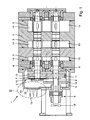
- Fig. 1 shows in section a vacuum pump 1, whose housing 2 essentially comprises two housing parts 3 and 4, namely pump chambers 3 and a gear 4 provided with a lubricant reservoir.
- the illustrated vacuum pump is a Roots vacuum pump.
- two shafts 6 and 7 are arranged horizontally rotatably supported by rolling bearings 8.
- the shaft 6 is driven by a drive 9, for example an asynchronous motor.
- a toothed wheel 11 is arranged as part of a transmission 10 in the gear chamber 4, which in the illustrated embodiment of a two-shaft vacuum pump 1 is engaged with a second toothed wheel 12 mounted on the shaft 7.
- Fig. 1 how to continue Fig. 1 it can be seen that the housing part 4 having the gear 10 can be closed to the environment via a gear cover 13 that can be fixed to the rest of the housing 2.
- pistons 14 and 15 are arranged, which cause the pump effect during rotation of the shafts 6 and 7 and at least one suction port (not shown) sucking fluid into the pump chambers 3 and at least one Discharge opening (not shown) again from the pump chambers 3.
- the pistons 14, 15 are designed as double-bow rotors.
- the shape of the pistons 14, 15 has approximately the shape of the numeral "8".
- the pistons 14, 15 are arranged in a rotor chamber formed by the housing part 3 with a minimum distance between a peripheral surface of the housing part 3 and the pistons 14, 15.
- the drive shaft 6 is rotated by the drive 9, for example, an electric motor.
- the output shaft 7 is rotated in the opposite direction to the drive shaft 6 by the engagement relationship between a drive gear 11 and an output gear 12 and the drive rotor 15 and the output rotor 14 are accordingly rotated.
- both the gears 11 and 12 and the rolling bearings 8 must be supplied with a lubricant in order to cool them and to avoid increased wear.
- the gear chamber 4 has a lubricant reservoir 5 filled with a lubricant.
- a lubricant reservoir 5 a arranged on the shaft 6 slinger 16 immersed, which distributes the lubricant in the entire gear chamber 4 and in particular the rolling bearings 8 and the gears 11 and 12 supplies.
- cooling fins 17 are arranged on the outside of the housing, which increase the outer surface of the housing 2 and thus allow a better heat exchange with the environment.
- the vacuum pump 1 has a fan 18 coupled to the drive 9, via which an air flow is generated, which can be guided for cooling along the cooling fins.
- This provided with the cooling fins 19 portion 20 of the gear cover 13 is sealed by preferably O-rings sealing elements 21 against the gear cover 13 sealed, as in Fig. 2 shown.
- the arrangement of the cooling ribs 19 on a portion 20 of the gear cover 13, the surface of the gear cover and thus the heat exchange with the environment available housing surface is increased.
- the design of the cooling fins 19 on a separate, releasably fixable on the gear cover 13 portion 20 has the advantage that this portion 20 depending on the application of a different material than the rest of the gear cover 13 may consist and the shape and internal configuration of the cooling fins 19 individually respective requirements is customizable.
- the cooling ribs 17, which are formed on the housing 2 in particular in the region of the drive 9, are a direct component of the housing 2 and thus also made of the same material as the housing 2.
- the gear cover 13 must have such a strength that the drive 9, which is mounted on the gear cover 13, this does not distort and is supported by this.
- the actual gear cover 13 is preferably made of cast material, particularly preferably made of cast iron.
- cooling fins 19 portion 20 of the gear cover 13 Since provided with the cooling fins 19 portion 20 of the gear cover 13 does not have to apply this carrying function, both the choice of material and the structural design of the cooling fins 19 can be tailored to the individual requirements of heat exchange.
- provided with the cooling fins 19 portion 20 of the gear cover 13 is made of a material having a high thermal conductivity.
- the cooling fins 19 have a triangular shape in cross section.
- the cooling fins 19 have a high aspect ratio, that is, the ratio of height to width or depth to width is large, which corresponds to a large surface area of the cooling fin 19 with respect to the base surface of the cooling fin 19.
- the cooling fins 19 are formed as a hollow triangular bulges and indentations.
- cooling fins 19 as hollow bulges
- warm lubricant and warm air from the lubricant reservoir 5 or the gear chamber 4 can enter the hollow bulges and release heat to the cooler environment via the large surface of the cooling fins 19.
- the hollow cooling rib 19 filled with cool ambient air projects into the warm gear chamber 4 and, via the large surface of the cooling rib 19, allows heat to be discharged from the interior of the warm gear chamber 4 to the outside.
- the cooling fins 19 are formed exclusively as a hollow triangular bulges.
- the heat exchange takes place, as already described above, in that warm lubricant and warm air from the lubricant reservoir 5 or the gear chamber 4 enter the hollow bulges and release heat to the cooler environment via the large surface of the cooling ribs 19.
- the cooling fins 19 are also formed exclusively as a triangular bulges, but in this case not as hollow ribs, but made of solid material.
- the length or height of a cooling rib 19 made of solid material is significantly lower than that of a hollow rib, since the brought about by heat conduction heat exchange with the cooler environment is meaningful feasible only over a limited length.
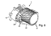
- the cooling capacity of the fan 18 can be increased in particular in the region of the portion 20 of the gear cover 13 provided with the cooling ribs 19 in that the air flow of the fan 18 via baffles 22, as in Fig. 6 shown, the arranged on the portion 20 of the gear cover 13 cooling fins 19 is supplied.
- the baffles 22 may also be formed as an air duct to suck warm air from the housing 2 via the air duct on demand by means of the fan 18.
- the shape and number of the cooling fins 17 and 19 and the shape of the baffles 22 can each be adapted to the individual requirements of the respective vacuum pump 1 and its operating situation.
Landscapes
- Engineering & Computer Science (AREA)
- Mechanical Engineering (AREA)
- General Engineering & Computer Science (AREA)
- Applications Or Details Of Rotary Compressors (AREA)
Abstract
Description
- Die Erfindung betrifft eine Vakuumpumpe mit einem Gehäuse, mindestens einer in dem Gehäuse angeordneten, über einen Antrieb drehbar angetriebenen Welle sowie mit einem mit der mindestens einen Welle gekoppelten Getriebe, wobei in einem das Getriebe aufweisenden Gehäuseteil des Gehäuses ein Schmiermittelspeicher zur Aufnahme eines Schmiermittels angeordnet ist und wobei der das Getriebe aufweisende Gehäuseteil über einen am übrigen Gehäuse festlegbaren Getriebedeckel gegenüber der Umgebung verschließbar ist.
- Die Entwicklung der Vakuumpumpen geht hin zu Vakuumpumpen mit einer hoher Leistungsdichte und einem kompakten Pumpengehäuse. Aufgrund der geringen Gehäuseaußenfläche stellt hierbei die Kühlung des Pumpengehäuses trotz deren Verrippung eine besondere Herausforderung dar. Überschreitet die Leistungsdichte ein gewisses Maß, kann durch freie Konvektion keine gleichmäßige Temperaturverteilung über die verschiedenen Bauteile mehr gewährleistet werden. Dies ist aber bei Vakuumpumpen erforderlich, um bei den relativ engen Spalten zwischen den bewegten Bauteilen ein Anlaufen der Teile untereinander mit möglichen Folgeschäden für das gesamte System zu vermeiden.
- Während die Gehäusebauteile Temperaturen von über 100 °C in der Regel ohne Schaden überstehen, stoßen Betriebsmittel, wie beispielsweise die zur Schmierung der Wellenlager und Getriebezahnräder dienenden Schmiermittel bei erhöhten Temperaturen an ihre Grenzen. Diese altern vorzeitig und Bauteile, die von optimalen Schmiereigenschaften abhängig sind, wie beispielsweise Getriebezahnräder, Wälzlager und auch berührende Dichtungen, weisen eine verkürzte Lebensdauer auf und bedingen kürzere Serviceintervalle.
- Aus der Praxis ist es bekannt, Vakuumpumpen mit einer Wasserkühlung zu versehen. Diese Kühlungsart erfordert aber ein speziell darauf ausgelegtes Design des gesamten Systems und ist für den Betreiber der Pumpen mit deutlich erhöhten Betriebskosten verbunden.
- Eine Mehrwellenvakuumpumpe ist beispielsweise aus der
DE 295 22 263 U1 bekannt. Mehrwellenvakuumpumpen sind beispielsweise Wälzkolbenvakuumpumpen. - Von dem Stand der Technik ausgehend liegt der Erfindung das technische Problem zugrunde, eine Vakuumpumpe zu schaffen, die bei kompakter Bauweise gute Kühleigenschaften aufweist.
- Dieses technische Problem wird mit einer Vakuumpumpe mit den Merkmalen gemäß Anspruch 1 gelöst.
- Die erfindungsgemäße Vakuumpumpe mit einem Gehäuse, mindestens einer in dem Gehäuse angeordneten, über einen Antrieb drehbar angetriebenen Welle sowie mit einem mit der mindestens einen Welle gekoppelten Getriebe, wobei in einem das Getriebe aufweisenden Gehäuseteil des Gehäuses ein Schmiermittelspeicher zur Aufnahme eines Schmiermittels angeordnet ist und wobei der das Getriebe aufweisende Gehäuseteil über einen am übrigen Gehäuse festlegbaren Getriebedeckel gegenüber der Umgebung verschließbar ist, zeichnet sich dadurch aus, dass der Getriebedeckel einen lösbar mit dem Getriebedeckel verbindbaren Teilbereich aufweist, der mit Kühlrippen versehen ist.
- Durch die Anordnung der Kühlrippen an einem Teilbereich des Getriebedeckels wird die Oberfläche des Getriebedeckels und somit die zum Wärmeaustausch mit der Umgebung zur Verfügung stehende Gehäusefläche vergrößert. Die Ausbildung der Kühlrippen an einem separaten am Getriebedeckel lösbar festlegbaren Teilbereich hat den Vorteil, dass dieser Teilbereich je nach Anwendungsbereich aus einem anderen Material als der übrige Getriebedeckel bestehen kann und auch die Form und innere Ausgestaltung der Kühlrippen individuell den jeweiligen Anforderungen anpassbar ist.
- Vorteilhafterweise besteht der die Kühlrippen aufweisende Teilbereich des Getriebedeckels aus einem Material mit einer hohen Wärmeleitfähigkeit.
- Gemäß einer praktischen Ausführungsform der Erfindung wird vorgeschlagen, dass die Kühlrippen als Ausbuchtungen und/oder Einbuchtungen in dem Teilbereich des Getriebedeckels ausgebildet sind. Die Kühlrippen vergrößern die zum Wärmeaustausch zur Verfügung stehende äußere Oberfläche des Getriebedeckels beziehungsweise des gesamten Gehäuses der Vakuumpumpe.
- Zur Optimierung des Wärmeaustauschs über die Kühlrippen wird mit der Erfindung vorgeschlagen, dass die Kühlrippen ein hohes Aspektverhältnis aufweisen, das heißt, dass das Verhältnis Höhe zu Breite beziehungsweise Tiefe zu Breite groß ist, was einer großen Oberfläche der Kühlrippe in Bezug auf die Grundfläche der Kühlrippe entspricht.
- Gemäß einer vorteilhaften Ausführungsform der Erfindung sind die Kühlrippen im Querschnitt vieleckförmig oder ovalförmig ausgebildet.
- Gemäß einer bevorzugten Ausführungsform der Erfindung wird vorgeschlagen, dass die Kühlrippen im Querschnitt dreieckförmig ausgebildet sind.
- Bei der Ausbildung der Kühlrippen als Ausbuchtungen und/oder Einbuchtungen in dem Teilbereich des Getriebedeckels wird erfindungsgemäß vorgeschlagen, dass die Kühlrippen als Hohlrippen ausgebildet sind. Im Falle der Ausbildung der Kühlrippen als Ausbuchtungen kann warmes Schmiermittel und warme Luft aus dem den Schmiermittelspeicher aufweisenden Gehäuseteil in die hohlen Ausbuchtungen eintreten und über die große Oberfläche der Kühlrippe Wärme an die kühlere Umgebung abgeben.
- Im Falle der Ausbildung der Kühlrippen als Einbuchtungen ragt die mit kühler Umgebungsluft gefüllte hohle Kühlrippe in den warmen Gehäuseteil und ermöglicht über die große Oberfläche der Kühlrippe Wärme aus dem Inneren des warmen Gehäuseteils nach außen abzuleiten.
- Gemäß einer alternativen Ausführungsform der Erfindung wird vorgeschlagen, dass die als Ausbuchtungen ausgebildeten Kühlrippen aus Vollmaterial bestehen. Die Länge beziehungsweise Höhe einer aus Vollmaterial hergestellten Kühlrippe ist deutlich geringer als die einer hohlen Rippe, da der durch Wärmeleitung herbeigeführte Wärmeaustausch mit der kühleren Umgebung nur über eine begrenzte Länge sinnvoll durchführbar ist.
- Um die Fluiddichtigkeit des Gehäuses und insbesondere des Getriebedeckels zu gewährleisten, wird mit der Erfindung vorgeschlagen, dass der mit den Kühlrippen versehene Teilbereich des Getriebedeckels über Dichtungselemente, vorzugsweise O-Ringe, gegenüber dem Getriebedeckel abgedichtet ist.
- Zur Verbesserung des Wärmeaustauschs wird mit der Erfindung weiterhin vorgeschlagen, dass auf der Außenseite des Gehäuses mindestens ein Lüfter zum Kühlen der Außenseite des Gehäuses angeordnet ist. Dieser Lüfter kann beispielsweise mit dem Antrieb der Vakuumpumpe gekoppelt sein und von diesem angetrieben werden.
- Die Kühlleistung des Lüfters im Bereich des mit den Kühlrippen versehenen Getriebedeckels lässt sich erfindungsgemäß dadurch steigern, dass der Luftstrom des Lüfters über Leitbleche den auf dem Teilbereich des Getriebedeckels angeordneten Kühlrippen zuführbar ist.
- Schließlich wird mit der Erfindung vorgeschlagen, dass mindestens ein Leitblech als Luftleitkanal ausgebildet ist und bei Bedarf über den mindestens einen Luftleitkanal auch warme Luft vom Gehäuse fort absaugbar ist.
- Weitere Merkmale und Vorteile der Erfindung ergeben sich anhand der zugehörigen Zeichnungen, in denen verschiedene Ausführungsbeispiele einer erfindungsgemäßen Vakuumpumpe nur beispielhaft dargestellt sind, ohne die Erfindung auf diese Ausführungsbeispiele zu beschränken. In den Zeichnungen zeigen:
- Fig. 1
- einen schematischen Längsschnitt durch eine erfindungsgemäße Vakuumpumpe;
- Fig. 2
- eine vergrößerte Ansicht des Details II, eine erste Ausführungsform darstellend;
- Fig. 3
- eine Ansicht gemäß
Fig. 2 , jedoch eine zweite Ausführungsform darstellend; - Fig. 4
- eine Ansicht gemäß
Fig. 2 , jedoch eine dritte Ausführungsform darstellend; - Fig. 5
- eine teilweise perspektivische Außenansicht des Gehäuses einer erfindungsgemäßen Vakuumpumpe;
- Fig. 6
- eine Ansicht gemäß
Fig. 5 , jedoch das Gehäuse mit Luftleitblechen darstellend. -
Fig. 1 zeigt im Schnitt eine Vakuumpumpe 1, deren Gehäuse 2 im Wesentlichen zwei Gehäuseteile 3 und 4 aufweist, nämlich Schöpfräume 3 und einen mit einem Schmiermittelspeicher 5 versehenen Getrieberaum 4. - Die in
Fig. 1 dargestellte Vakuumpumpe ist eine Wälzkolbenvakuumpumpe. - Im Gehäuse 2 sind zwei Wellen 6 und 7 über Wälzlager 8 horizontal drehbar gelagert angeordnet. Die Welle 6 wird über einen Antrieb 9, beispielsweise einen Asynchronmotor, angetrieben. Auf der vom Antrieb 9 angetriebenen Welle 6 ist als Bestandteil eines Getriebes 10 im Getrieberaum 4 ein Zahnrad 11 angeordnet, das bei der dargestellten Ausführungsform einer Zweiwellen-Vakuumpumpe 1 mit einem auf der Welle 7 gelagerten zweiten Zahnrad 12 in Eingriff steht.
- Wie weiterhin aus
Fig. 1 ersichtlich, ist der das Getriebe 10 aufweisende Gehäuseteil 4 über einen am übrigen Gehäuse 2 festlegbaren Getriebedeckel 13 gegenüber der Umgebung verschließbar. - Auf den die Schöpfräume 3 durchsetzenden Teilen der Wellen 6 und 7 sind Kolben 14 und 15 angeordnet, die bei der Drehung der Wellen 6 und 7 den Pumpeffekt bewirken und über mindestens eine Ansaugöffnung (nicht dargestellt) Fluid in die Schöpfräume 3 ansaugen und über mindestens eine Ausstoßöffnung (nicht dargestellt) wieder aus den Schöpfräumen 3 austragen.
- Die Kolben 14, 15 sind als zweibogige Rotoren ausgebildet.
- Die Form der Kolben 14, 15 hat annähernd die Form der Ziffer "8".
- Die Kolben 14, 15 sind in einer durch das Gehäuseteil 3 gebildeten Rotorkammer angeordnet mit einem minimalen Abstand zwischen einer Umfangsfläche des Gehäuseteiles 3 und den Kolben 14, 15. Darüber hinaus haben die Kolben 14, 15, wenn sie miteinander eingreifen, einen minimalen Abstand zwischen sich ausgebildet, um zu verhindern, dass sie direkt miteinander eingreifen, beziehungsweise sich behindern. Bei dem Betrieb der Wälzkolbenvakuumpumpe 1 wird die Antriebswelle 6 durch den Antrieb 9, beispielsweise einen Elektromotor gedreht. Hierdurch wird die Abtriebswelle 7 in Gegenrichtung zu der Antriebswelle 6 durch die Eingreifbeziehung zwischen einem Antriebszahnrad 11 und einem Abtriebszahnrad 12 gedreht und der Antriebsrotor 15 und der Abtriebsrotor 14 werden demzufolge gedreht.
- Sowohl die Zahnräder 11 und 12 als auch die Wälzlager 8 müssen mit einem Schmiermittel versorgt werden, um diese zu kühlen und einen erhöhten Verschleiß zu vermeiden. Zu diesem Zweck weist der Getrieberaum 4 einen mit einem Schmiermittel befüllten Schmiermittelspeicher 5 auf. In den Schmiermittelspeicher 5 taucht eine auf der Welle 6 angeordnete Schleuderscheibe 16 ein, die das Schmiermittel in dem gesamten Getrieberaum 4 verteilt und insbesondere den Wälzlagern 8 und den Zahnrädern 11 und 12 zuführt.
- Während die Bauteile des Gehäuses 2 und 13 Temperaturen von über 100 °C in der Regel ohne Schaden überstehen, stoßen Betriebsmittel, wie beispielsweise die zur Schmierung der Wälzlager 8 dienenden Schmiermittel bei erhöhten Temperaturen an ihre Grenzen. Diese altern vorzeitig und Bauteile, die von optimalen Schmiereigenschaften abhängig sind, wie beispielsweise die Getriebezahnräder 11 und 12, Wälzlager 8 und auch berührende Dichtungen, weisen eine verkürzte Lebensdauer auf und bedingen kürzere Serviceintervalle.
- Aus diesem Grunde ist es erforderlich den Getrieberaum 4 und/oder das in dem Schmiermittelspeicher 5 befindliche Schmiermittel direkt oder indirekt zu kühlen.
- Wie aus den
Fig. 5 und6 ersichtlich, sind auf der Außenseite des Gehäuses 2 Kühlrippen 17 angeordnet, die die äußere Oberfläche des Gehäuses 2 vergrößern und so einen besseren Wärmeaustausch mit der Umgebung ermöglichen. Bei der inFig. 1 dargestellten Ausführungsform weist die Vakuumpumpe 1 einen mit dem Antrieb 9 gekoppelten Lüfter 18 auf, über den ein Luftstrom erzeugt wird, der zum Kühlen entlang der Kühlrippen führbar ist. - Als Besonderheit weisen die dargestellten Ausführungsformen einer Vakuumpumpe Kühlrippen 19 im Bereich des Getriebedeckels 13 auf, die auf einen lösbar mit dem Getriebedeckel 13 verbindbaren Teilbereich 20 angeordnet sind. Dieser mit den Kühlrippen 19 versehene Teilbereich 20 des Getriebedeckels 13 ist über vorzugsweise O-Ringe ausgebildete Dichtungselemente 21 gegenüber dem Getriebedeckel 13 abgedichtet, wie in
Fig. 2 dargestellt. - Durch die Anordnung der Kühlrippen 19 an einem Teilbereich 20 des Getriebedeckels 13 wird die Oberfläche des Getriebedeckels und somit die zum Wärmeaustausch mit der Umgebung zur Verfügung stehende Gehäusefläche vergrößert. Die Ausbildung der Kühlrippen 19 an einem separaten, am Getriebedeckel 13 lösbar festlegbaren Teilbereich 20 hat den Vorteil, dass dieser Teilbereich 20 je nach Anwendungsbereich aus einem anderen Material als der übrige Getriebedeckel 13 bestehen kann und auch die Form und innere Ausgestaltung der Kühlrippen 19 individuell den jeweiligen Anforderungen anpassbar ist.
- Die insbesondere im Bereich des Antriebs 9 am Gehäuse 2 ausgebildeten Kühlrippen 17 sind unmittelbarer Bestandteil des Gehäuses 2 und somit auch aus demselben Material wie das Gehäuse 2 gefertigt.
- Der Getriebedeckel 13 muss eine solche Festigkeit aufweisen, dass der Antrieb 9, der am Getriebedeckel 13 gelagert ist, diesen nicht verzieht und von diesem getragen wird. Aus diesem Grunde besteht der eigentliche Getriebedeckel 13 vorzugsweise aus Gussmaterial, besonders bevorzugt aus Eisenguss.
- Da der mit den Kühlrippen 19 versehene Teilbereich 20 des Getriebedeckels 13 diese Tragefunktion nicht aufbringen muss, kann hier sowohl die Materialwahl als auch die konstruktive Ausgestaltung der Kühlrippen 19 auf die individuellen Anforderungen des Wärmeaustauschs abgestimmt werden. Vorzugsweise besteht der mit den Kühlrippen 19 versehene Teilbereich 20 des Getriebedeckels 13 aus einem Material mit einer hohen Wärmeleitfähigkeit.
- Bei den in den
Fig. 1 bis 6 dargestellten Ausführungsformen weisen die Kühlrippen 19 eine im Querschnitt dreieckige Form auf. Zur Optimierung des Wärmeaustauschs über die Kühlrippen 19 weisen die Kühlrippen 19 ein hohes Aspektverhältnis auf, das heißt, dass das Verhältnis Höhe zu Breite beziehungsweise Tiefe zu Breite groß ist, was einer großen Oberfläche der Kühlrippe 19 in Bezug auf die Grundfläche der Kühlrippe 19 entspricht. - In den
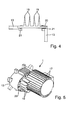
Fig. 2 bis 4 sind beispielhaft drei verschiedene Ausführungsformen zur Ausbildung der an dem Teilbereich 20 des Getriebedeckels 13 ausgebildeten Kühlrippen 19 dargestellt. - Bei der in
Fig. 2 dargestellten ersten Ausführungsform sind die Kühlrippen 19 als hohle dreieckförmige Ausbuchtungen und Einbuchtungen ausgebildet. - Im Falle der Ausbildung der Kühlrippen 19 als hohle Ausbuchtungen kann warmes Schmiermittel und warme Luft aus dem Schmiermittelspeicher 5 beziehungsweise dem Getrieberaum 4 in die hohlen Ausbuchtungen eintreten und über die große Oberfläche der Kühlrippen 19 Wärme an die kühlere Umgebung abgeben.
- Im Falle der Ausbildung der Kühlrippen als Einbuchtungen ragt die mit kühler Umgebungsluft gefüllte hohle Kühlrippe 19 in den warmen Getrieberaum 4 hinein und ermöglicht über die große Oberfläche der Kühlrippe 19, Wärme aus dem Inneren des warmen Getrieberaums 4 nach außen abzuleiten.
- Bei der in
Fig. 3 dargestellten zweiten Ausführungsform sind die Kühlrippen 19 ausschließlich als hohle dreieckförmige Ausbuchtungen ausgebildet. Hier erfolgt der Wärmeaustausch wie bereits zuvor beschrieben dadurch, dass warmes Schmiermittel und warme Luft aus dem Schmiermittelspeicher 5 beziehungsweise dem Getrieberaum 4 in die hohlen Ausbuchtungen eintritt und über die große Oberfläche der Kühlrippen 19 Wärme an die kühlere Umgebung abgeben wird. - Bei der in
Fig. 4 dargestellten dritten Ausführungsform sind die Kühlrippen 19 ebenfalls ausschließlich als dreieckförmige Ausbuchtungen ausgebildet, jedoch in diesem Falle nicht als Hohlrippen, sondern aus Vollmaterial bestehend. - Die Länge beziehungsweise Höhe einer aus Vollmaterial hergestellten Kühlrippe 19 ist deutlich geringer als die einer hohlen Rippe, da der durch Wärmeleitung herbeigeführte Wärmeaustausch mit der kühleren Umgebung nur über eine begrenzte Länge sinnvoll durchführbar ist.
- Die Kühlleistung des Lüfters 18 lässt sich insbesondere im Bereich des mit den Kühlrippen 19 versehenen Teilbereichs 20 des Getriebedeckels 13 dadurch steigern, dass der Luftstrom des Lüfters 18 über Leitbleche 22, wie in
Fig. 6 dargestellt, den auf dem Teilbereich 20 des Getriebedeckels 13 angeordneten Kühlrippen 19 zugeführt wird. - Alternativ zum Zuführen von kühler Luft hin zu den Kühlrippen 19 können die Leitbleche 22 auch als Luftleitkanal ausgebildet sein, um bei Bedarf mittels des Lüfters 18 über den Luftleitkanal warme Luft vom Gehäuse 2 fort abzusaugen.
- Die Form und Anzahl der Kühlrippen 17 und 19 sowie die Form der Leitbleche 22 ist jeweils an die individuellen Anforderungen der jeweiligen Vakuumpumpe 1 und deren Betriebssituation anpassbar. So ist es beispielsweise möglich, Löcher mit variablem Öffnungsquerschnitt in den Leitblechen 22 vorzusehen, um je nach Erfordernis mehr oder weniger Kaltluft zuführen zu können.
- Weiterhin ist es gemäß einer alternativen Ausführungsform selbstverständlich auch möglich, einen oder mehrere externe Lüfter vorzusehen, um insbesondere lokale Temperaturüberhöhungen abzuschwächen.
-
- 1
- Vakuumpumpe
- 2
- Gehäuse
- 3
- Gehäuseteil des Schöpfraumes
- 4
- Gehäuseteil des Getrieberaumes
- 5
- Schmiermittelspeicher
- 6
- Welle
- 7
- Welle
- 8
- Wälzlager
- 9
- Antrieb
- 10
- Getriebe
- 11
- Zahnrad
- 12
- Zahnrad
- 13
- Getriebedeckel
- 14
- Kolben
- 15
- Kolben
- 16
- Schleuderscheibe
- 17
- Kühlrippe
- 18
- Lüfter
- 19
- Kühlrippe
- 20
- Teilbereich
- 21
- Dichtungselement
- 22
- Leitblech
Claims (15)
- Vakuumpumpe mit einem Gehäuse, mindestens einer in dem Gehäuse angeordneten, über einen Antrieb drehbar angetriebenen Welle sowie mit einem mit der mindestens einen Welle gekoppelten Getriebe, wobei in einem das Getriebe aufweisenden Gehäuseteil des Gehäuses ein Schmiermittelspeicher zur Aufnahme eines Schmiermittels angeordnet ist und wobei der das Getriebe aufweisende Gehäuseteil über einen am übrigen Gehäuse festlegbaren Getriebedeckel gegenüber der Umgebung verschließbar ist,
dadurch gekennzeichnet, dass der Getriebedeckel (13) einen lösbar mit dem Getriebedeckel (13) verbindbaren Teilbereich (20) aufweist, der mit Kühlrippen (19) versehen ist. - Vakuumpumpe nach Anspruch 1, dadurch gekennzeichnet, dass die Kühlrippen (19) als Ausbuchtungen und/oder Einbuchtungen in dem Teilbereich (20) des Getriebedeckels (13) ausgebildet sind.
- Vakuumpumpe nach Anspruch 1 oder 2, dadurch gekennzeichnet, dass die Kühlrippen (19) ein hohes Aspektverhältnis aufweisen.
- Vakuumpumpe nach einem der Ansprüche 1 bis 3, dadurch gekennzeichnet, dass die Kühlrippen (19) im Querschnitt vieleckförmig oder ovalförmig ausgebildet sind.
- Vakuumpumpe nach Anspruch 4, dadurch gekennzeichnet, dass die Kühlrippen (19) im Querschnitt dreieckförmig ausgebildet sind.
- Vakuumpumpe nach einem der Ansprüche 2 bis 5, dadurch gekennzeichnet, dass die als Ausbuchtungen und/oder Einbuchtungen ausgebildeten Kühlrippen (19) hohl sind.
- Vakuumpumpe nach einem der Ansprüche 2 bis 5, dadurch gekennzeichnet, dass die als Ausbuchtungen ausgebildeten Kühlrippen (19) aus Vollmaterial bestehen.
- Vakuumpumpe nach einem der Ansprüche 1 bis 7, dadurch gekennzeichnet, dass der mit den Kühlrippen (19) versehene Teilbereich (20) des Getriebedeckels (13) über Dichtungselemente (21), vorzugsweise O-Ringe, gegenüber dem Getriebedeckel (13) abgedichtet ist.
- Vakuumpumpe nach Anspruch 8, dadurch gekennzeichnet, dass wenigstens ein Dichtungselement (21) als O-Ring ausgebildet ist.
- Vakuumpumpe nach einem der Ansprüche 1 bis 9, dadurch gekennzeichnet, dass auf der Außenseite des Gehäuses (2) mindestens ein Lüfter (18) zum Kühlen der Außenseite des Gehäuses (2) angeordnet ist.
- Vakuumpumpe nach Anspruch 10, dadurch gekennzeichnet, dass der Luftstrom des Lüfters (18) über Leitbleche (22) den auf dem Teilbereich (20) des Getriebedeckels (13) angeordneten Kühlrippen (19) zuführbar ist.
- Vakuumpumpe nach Anspruch 11, dadurch gekennzeichnet, dass mindestens ein Leitblech (22) als Luftleitkanal ausgebildet ist.
- Vakuumpumpe nach Anspruch 11, dadurch gekennzeichnet, dass wenigstens ein Leitblech (22) Öffnungen mit einem variablen Öffnungsquerschnitt aufweist.
- Vakuumpumpe nach Anspruch 12, dadurch gekennzeichnet, dass über den mindestens einen Luftleitkanal warme Luft vom Gehäuse (2) fort absaugbar ist.
- Vakuumpumpe nach einem der Ansprüche 1 bis 14, dadurch gekennzeichnet, dass der mit den Kühlrippen (19) versehene Teilbereich (20) des Getriebedeckels (13) aus einem Material mit einer hohen Wärmeleitfähigkeit besteht.
Applications Claiming Priority (1)
| Application Number | Priority Date | Filing Date | Title |
|---|---|---|---|
| DE102014107684.2A DE102014107684A1 (de) | 2014-06-02 | 2014-06-02 | Vakuumpumpe |
Publications (2)
| Publication Number | Publication Date |
|---|---|
| EP2952678A1 true EP2952678A1 (de) | 2015-12-09 |
| EP2952678B1 EP2952678B1 (de) | 2023-11-22 |
Family
ID=53008335
Family Applications (1)
| Application Number | Title | Priority Date | Filing Date |
|---|---|---|---|
| EP15164991.0A Active EP2952678B1 (de) | 2014-06-02 | 2015-04-24 | Vakuumpumpe mit kühlrippen |
Country Status (2)
| Country | Link |
|---|---|
| EP (1) | EP2952678B1 (de) |
| DE (1) | DE102014107684A1 (de) |
Cited By (4)
| Publication number | Priority date | Publication date | Assignee | Title |
|---|---|---|---|---|
| CN106989165A (zh) * | 2017-05-25 | 2017-07-28 | 贵州大学 | 一种用于液力变速器散热型壳体 |
| CN107061284A (zh) * | 2017-04-11 | 2017-08-18 | 浙江神工真空设备制造有限公司 | 一种罗茨真空泵 |
| EP3396163A1 (de) * | 2017-04-28 | 2018-10-31 | Pfeiffer Vacuum Gmbh | Vakuumpumpe mit schmiermittelpegel-begrenzungsvorrichtung |
| CN114458601A (zh) * | 2021-12-29 | 2022-05-10 | 中科仪(南通)半导体设备有限责任公司 | 一种罗茨真空泵润滑结构 |
Citations (2)
| Publication number | Priority date | Publication date | Assignee | Title |
|---|---|---|---|---|
| DE29522263U1 (de) | 1995-12-02 | 2001-08-02 | Pfeiffer Vacuum GmbH, 35614 Aßlar | Mehrwellenvakuumpumpe |
| JP2002115690A (ja) * | 2000-10-12 | 2002-04-19 | Toyota Industries Corp | 真空ポンプにおける冷却構造 |
Family Cites Families (3)
| Publication number | Priority date | Publication date | Assignee | Title |
|---|---|---|---|---|
| DE19820622A1 (de) * | 1998-05-09 | 1999-11-11 | Peter Frieden | Demontierbare Vielzweckpumpe oder -kompressor für Chemie-, Verfahrens-, Lebensmittel- und Vakuumtechnik |
| DE29904410U1 (de) * | 1999-03-10 | 2000-07-20 | GHH-RAND Schraubenkompressoren GmbH & Co. KG, 46145 Oberhausen | Schraubenkompressor |
| JP2007198153A (ja) * | 2006-01-24 | 2007-08-09 | Anest Iwata Corp | スクロール流体機械 |
-
2014
- 2014-06-02 DE DE102014107684.2A patent/DE102014107684A1/de active Pending
-
2015
- 2015-04-24 EP EP15164991.0A patent/EP2952678B1/de active Active
Patent Citations (2)
| Publication number | Priority date | Publication date | Assignee | Title |
|---|---|---|---|---|
| DE29522263U1 (de) | 1995-12-02 | 2001-08-02 | Pfeiffer Vacuum GmbH, 35614 Aßlar | Mehrwellenvakuumpumpe |
| JP2002115690A (ja) * | 2000-10-12 | 2002-04-19 | Toyota Industries Corp | 真空ポンプにおける冷却構造 |
Cited By (5)
| Publication number | Priority date | Publication date | Assignee | Title |
|---|---|---|---|---|
| CN107061284A (zh) * | 2017-04-11 | 2017-08-18 | 浙江神工真空设备制造有限公司 | 一种罗茨真空泵 |
| EP3396163A1 (de) * | 2017-04-28 | 2018-10-31 | Pfeiffer Vacuum Gmbh | Vakuumpumpe mit schmiermittelpegel-begrenzungsvorrichtung |
| CN106989165A (zh) * | 2017-05-25 | 2017-07-28 | 贵州大学 | 一种用于液力变速器散热型壳体 |
| CN114458601A (zh) * | 2021-12-29 | 2022-05-10 | 中科仪(南通)半导体设备有限责任公司 | 一种罗茨真空泵润滑结构 |
| CN114458601B (zh) * | 2021-12-29 | 2022-12-16 | 中科仪(南通)半导体设备有限责任公司 | 一种罗茨真空泵润滑结构 |
Also Published As
| Publication number | Publication date |
|---|---|
| EP2952678B1 (de) | 2023-11-22 |
| DE102014107684A1 (de) | 2015-12-03 |
Similar Documents
| Publication | Publication Date | Title |
|---|---|---|
| WO2013050182A1 (de) | Elektromotorische getriebevorrichtung | |
| EP3482106B1 (de) | Getriebe und verwendung eines ringkühlers | |
| DE102010008584A1 (de) | Elektrische Antriebseinheit | |
| DE102015214309A1 (de) | Hohlwellenkühlung für einen Antrieb eines Elektrofahrzeugs | |
| DE102018220496A1 (de) | Gemeinsames Gehäuse für E-Maschine und Getriebe | |
| EP2952678B1 (de) | Vakuumpumpe mit kühlrippen | |
| DE102016202886A1 (de) | Flüssigkeitsgekühlte elektrische Maschine | |
| DE102017203527A1 (de) | Vorrichtung zur Kühlung und Schmierung eines Getriebes für ein Fahrzeug | |
| EP2686582B1 (de) | Getriebevorrichtung | |
| DE102012112379A1 (de) | Antriebsachse mit zumindest einem elektrischen Fahrmotor | |
| DE102009061042A1 (de) | Zumindest teilweise mit Öl befülltes Getriebe | |
| DE1933287A1 (de) | Rotationsmaschine | |
| DE102016203550B4 (de) | Getriebe für ein Kraftfahrzeug, Kraftfahrzeug und Verfahren zum Temperieren eines Getriebefluids | |
| EP3614022B1 (de) | Hybridgetriebe | |
| DE102017128551A1 (de) | Rotor mit Kühlung | |
| DE102014215758A1 (de) | Elektrische Maschine mit einem ersten Kreislauf und einem zweiten Kreislauf | |
| DE102014011096A1 (de) | Vorrichtung zur Konditionierung des Schmieröls einer Drehmomentübertragungseinrichtung | |
| WO2012123045A1 (de) | Getriebevorrichtung | |
| DE102023206959A1 (de) | Kühlsystem für eine Antriebseinrichtung eines Hybrid- oder Elektrofahrzeugs und Antriebseinrichtung mit einem solchen Kühlsystem | |
| DE102018106799A1 (de) | Elektrischer Antrieb | |
| EP2686584A1 (de) | Getriebevorrichtung | |
| EP2902629B1 (de) | Vakuumpumpe mit schmiermittelkühlvorrichtung | |
| EP2394091B1 (de) | Tragelement mit einer antriebseinheit | |
| DE102016004936B4 (de) | Elektrische Maschine | |
| DE102014015827A1 (de) | Elektrogerät, insbesondere Umrichter, insbesondere Umrichter zur Speisung eines ein Getriebe antreibenden Elektromotors |
Legal Events
| Date | Code | Title | Description |
|---|---|---|---|
| PUAI | Public reference made under article 153(3) epc to a published international application that has entered the european phase |
Free format text: ORIGINAL CODE: 0009012 |
|
| AK | Designated contracting states |
Kind code of ref document: A1 Designated state(s): AL AT BE BG CH CY CZ DE DK EE ES FI FR GB GR HR HU IE IS IT LI LT LU LV MC MK MT NL NO PL PT RO RS SE SI SK SM TR |
|
| AX | Request for extension of the european patent |
Extension state: BA ME |
|
| 17P | Request for examination filed |
Effective date: 20160602 |
|
| RBV | Designated contracting states (corrected) |
Designated state(s): AL AT BE BG CH CY CZ DE DK EE ES FI FR GB GR HR HU IE IS IT LI LT LU LV MC MK MT NL NO PL PT RO RS SE SI SK SM TR |
|
| STAA | Information on the status of an ep patent application or granted ep patent |
Free format text: STATUS: EXAMINATION IS IN PROGRESS |
|
| 17Q | First examination report despatched |
Effective date: 20190529 |
|
| GRAP | Despatch of communication of intention to grant a patent |
Free format text: ORIGINAL CODE: EPIDOSNIGR1 |
|
| STAA | Information on the status of an ep patent application or granted ep patent |
Free format text: STATUS: GRANT OF PATENT IS INTENDED |
|
| INTG | Intention to grant announced |
Effective date: 20230718 |
|
| GRAS | Grant fee paid |
Free format text: ORIGINAL CODE: EPIDOSNIGR3 |
|
| GRAA | (expected) grant |
Free format text: ORIGINAL CODE: 0009210 |
|
| STAA | Information on the status of an ep patent application or granted ep patent |
Free format text: STATUS: THE PATENT HAS BEEN GRANTED |
|
| AK | Designated contracting states |
Kind code of ref document: B1 Designated state(s): AL AT BE BG CH CY CZ DE DK EE ES FI FR GB GR HR HU IE IS IT LI LT LU LV MC MK MT NL NO PL PT RO RS SE SI SK SM TR |
|
| REG | Reference to a national code |
Ref country code: GB Ref legal event code: FG4D Free format text: NOT ENGLISH |
|
| REG | Reference to a national code |
Ref country code: CH Ref legal event code: EP |
|
| REG | Reference to a national code |
Ref country code: DE Ref legal event code: R096 Ref document number: 502015016681 Country of ref document: DE |
|
| REG | Reference to a national code |
Ref country code: IE Ref legal event code: FG4D Free format text: LANGUAGE OF EP DOCUMENT: GERMAN |
|
| REG | Reference to a national code |
Ref country code: LT Ref legal event code: MG9D |
|
| REG | Reference to a national code |
Ref country code: NL Ref legal event code: MP Effective date: 20231122 |
|
| PG25 | Lapsed in a contracting state [announced via postgrant information from national office to epo] |
Ref country code: GR Free format text: LAPSE BECAUSE OF FAILURE TO SUBMIT A TRANSLATION OF THE DESCRIPTION OR TO PAY THE FEE WITHIN THE PRESCRIBED TIME-LIMIT Effective date: 20240223 |
|
| PG25 | Lapsed in a contracting state [announced via postgrant information from national office to epo] |
Ref country code: IS Free format text: LAPSE BECAUSE OF FAILURE TO SUBMIT A TRANSLATION OF THE DESCRIPTION OR TO PAY THE FEE WITHIN THE PRESCRIBED TIME-LIMIT Effective date: 20240322 |
|
| PG25 | Lapsed in a contracting state [announced via postgrant information from national office to epo] |
Ref country code: LT Free format text: LAPSE BECAUSE OF FAILURE TO SUBMIT A TRANSLATION OF THE DESCRIPTION OR TO PAY THE FEE WITHIN THE PRESCRIBED TIME-LIMIT Effective date: 20231122 |
|
| PG25 | Lapsed in a contracting state [announced via postgrant information from national office to epo] |
Ref country code: NL Free format text: LAPSE BECAUSE OF FAILURE TO SUBMIT A TRANSLATION OF THE DESCRIPTION OR TO PAY THE FEE WITHIN THE PRESCRIBED TIME-LIMIT Effective date: 20231122 |
|
| PG25 | Lapsed in a contracting state [announced via postgrant information from national office to epo] |
Ref country code: ES Free format text: LAPSE BECAUSE OF FAILURE TO SUBMIT A TRANSLATION OF THE DESCRIPTION OR TO PAY THE FEE WITHIN THE PRESCRIBED TIME-LIMIT Effective date: 20231122 |
|
| PG25 | Lapsed in a contracting state [announced via postgrant information from national office to epo] |
Ref country code: NL Free format text: LAPSE BECAUSE OF FAILURE TO SUBMIT A TRANSLATION OF THE DESCRIPTION OR TO PAY THE FEE WITHIN THE PRESCRIBED TIME-LIMIT Effective date: 20231122 Ref country code: LT Free format text: LAPSE BECAUSE OF FAILURE TO SUBMIT A TRANSLATION OF THE DESCRIPTION OR TO PAY THE FEE WITHIN THE PRESCRIBED TIME-LIMIT Effective date: 20231122 Ref country code: IS Free format text: LAPSE BECAUSE OF FAILURE TO SUBMIT A TRANSLATION OF THE DESCRIPTION OR TO PAY THE FEE WITHIN THE PRESCRIBED TIME-LIMIT Effective date: 20240322 Ref country code: GR Free format text: LAPSE BECAUSE OF FAILURE TO SUBMIT A TRANSLATION OF THE DESCRIPTION OR TO PAY THE FEE WITHIN THE PRESCRIBED TIME-LIMIT Effective date: 20240223 Ref country code: ES Free format text: LAPSE BECAUSE OF FAILURE TO SUBMIT A TRANSLATION OF THE DESCRIPTION OR TO PAY THE FEE WITHIN THE PRESCRIBED TIME-LIMIT Effective date: 20231122 Ref country code: BG Free format text: LAPSE BECAUSE OF FAILURE TO SUBMIT A TRANSLATION OF THE DESCRIPTION OR TO PAY THE FEE WITHIN THE PRESCRIBED TIME-LIMIT Effective date: 20240222 Ref country code: PT Free format text: LAPSE BECAUSE OF FAILURE TO SUBMIT A TRANSLATION OF THE DESCRIPTION OR TO PAY THE FEE WITHIN THE PRESCRIBED TIME-LIMIT Effective date: 20240322 |
|
| PG25 | Lapsed in a contracting state [announced via postgrant information from national office to epo] |
Ref country code: SE Free format text: LAPSE BECAUSE OF FAILURE TO SUBMIT A TRANSLATION OF THE DESCRIPTION OR TO PAY THE FEE WITHIN THE PRESCRIBED TIME-LIMIT Effective date: 20231122 Ref country code: RS Free format text: LAPSE BECAUSE OF FAILURE TO SUBMIT A TRANSLATION OF THE DESCRIPTION OR TO PAY THE FEE WITHIN THE PRESCRIBED TIME-LIMIT Effective date: 20231122 Ref country code: PL Free format text: LAPSE BECAUSE OF FAILURE TO SUBMIT A TRANSLATION OF THE DESCRIPTION OR TO PAY THE FEE WITHIN THE PRESCRIBED TIME-LIMIT Effective date: 20231122 Ref country code: NO Free format text: LAPSE BECAUSE OF FAILURE TO SUBMIT A TRANSLATION OF THE DESCRIPTION OR TO PAY THE FEE WITHIN THE PRESCRIBED TIME-LIMIT Effective date: 20240222 Ref country code: LV Free format text: LAPSE BECAUSE OF FAILURE TO SUBMIT A TRANSLATION OF THE DESCRIPTION OR TO PAY THE FEE WITHIN THE PRESCRIBED TIME-LIMIT Effective date: 20231122 Ref country code: HR Free format text: LAPSE BECAUSE OF FAILURE TO SUBMIT A TRANSLATION OF THE DESCRIPTION OR TO PAY THE FEE WITHIN THE PRESCRIBED TIME-LIMIT Effective date: 20231122 |
|
| PG25 | Lapsed in a contracting state [announced via postgrant information from national office to epo] |
Ref country code: DK Free format text: LAPSE BECAUSE OF FAILURE TO SUBMIT A TRANSLATION OF THE DESCRIPTION OR TO PAY THE FEE WITHIN THE PRESCRIBED TIME-LIMIT Effective date: 20231122 |
|
| PG25 | Lapsed in a contracting state [announced via postgrant information from national office to epo] |
Ref country code: SK Free format text: LAPSE BECAUSE OF FAILURE TO SUBMIT A TRANSLATION OF THE DESCRIPTION OR TO PAY THE FEE WITHIN THE PRESCRIBED TIME-LIMIT Effective date: 20231122 |
|
| PG25 | Lapsed in a contracting state [announced via postgrant information from national office to epo] |
Ref country code: SM Free format text: LAPSE BECAUSE OF FAILURE TO SUBMIT A TRANSLATION OF THE DESCRIPTION OR TO PAY THE FEE WITHIN THE PRESCRIBED TIME-LIMIT Effective date: 20231122 Ref country code: SK Free format text: LAPSE BECAUSE OF FAILURE TO SUBMIT A TRANSLATION OF THE DESCRIPTION OR TO PAY THE FEE WITHIN THE PRESCRIBED TIME-LIMIT Effective date: 20231122 Ref country code: RO Free format text: LAPSE BECAUSE OF FAILURE TO SUBMIT A TRANSLATION OF THE DESCRIPTION OR TO PAY THE FEE WITHIN THE PRESCRIBED TIME-LIMIT Effective date: 20231122 Ref country code: EE Free format text: LAPSE BECAUSE OF FAILURE TO SUBMIT A TRANSLATION OF THE DESCRIPTION OR TO PAY THE FEE WITHIN THE PRESCRIBED TIME-LIMIT Effective date: 20231122 Ref country code: DK Free format text: LAPSE BECAUSE OF FAILURE TO SUBMIT A TRANSLATION OF THE DESCRIPTION OR TO PAY THE FEE WITHIN THE PRESCRIBED TIME-LIMIT Effective date: 20231122 |
|
| REG | Reference to a national code |
Ref country code: DE Ref legal event code: R097 Ref document number: 502015016681 Country of ref document: DE |
|
| PLBE | No opposition filed within time limit |
Free format text: ORIGINAL CODE: 0009261 |
|
| STAA | Information on the status of an ep patent application or granted ep patent |
Free format text: STATUS: NO OPPOSITION FILED WITHIN TIME LIMIT |
|
| PG25 | Lapsed in a contracting state [announced via postgrant information from national office to epo] |
Ref country code: SI Free format text: LAPSE BECAUSE OF FAILURE TO SUBMIT A TRANSLATION OF THE DESCRIPTION OR TO PAY THE FEE WITHIN THE PRESCRIBED TIME-LIMIT Effective date: 20231122 |
|
| 26N | No opposition filed |
Effective date: 20240823 |
|
| PG25 | Lapsed in a contracting state [announced via postgrant information from national office to epo] |
Ref country code: SI Free format text: LAPSE BECAUSE OF FAILURE TO SUBMIT A TRANSLATION OF THE DESCRIPTION OR TO PAY THE FEE WITHIN THE PRESCRIBED TIME-LIMIT Effective date: 20231122 |
|
| PG25 | Lapsed in a contracting state [announced via postgrant information from national office to epo] |
Ref country code: MC Free format text: LAPSE BECAUSE OF FAILURE TO SUBMIT A TRANSLATION OF THE DESCRIPTION OR TO PAY THE FEE WITHIN THE PRESCRIBED TIME-LIMIT Effective date: 20231122 |
|
| PG25 | Lapsed in a contracting state [announced via postgrant information from national office to epo] |
Ref country code: MC Free format text: LAPSE BECAUSE OF FAILURE TO SUBMIT A TRANSLATION OF THE DESCRIPTION OR TO PAY THE FEE WITHIN THE PRESCRIBED TIME-LIMIT Effective date: 20231122 |
|
| REG | Reference to a national code |
Ref country code: CH Ref legal event code: PL |
|
| PG25 | Lapsed in a contracting state [announced via postgrant information from national office to epo] |
Ref country code: LU Free format text: LAPSE BECAUSE OF NON-PAYMENT OF DUE FEES Effective date: 20240424 |
|
| REG | Reference to a national code |
Ref country code: BE Ref legal event code: MM Effective date: 20240430 |
|
| PG25 | Lapsed in a contracting state [announced via postgrant information from national office to epo] |
Ref country code: LU Free format text: LAPSE BECAUSE OF NON-PAYMENT OF DUE FEES Effective date: 20240424 |
|
| PG25 | Lapsed in a contracting state [announced via postgrant information from national office to epo] |
Ref country code: BE Free format text: LAPSE BECAUSE OF NON-PAYMENT OF DUE FEES Effective date: 20240430 |
|
| PG25 | Lapsed in a contracting state [announced via postgrant information from national office to epo] |
Ref country code: FR Free format text: LAPSE BECAUSE OF NON-PAYMENT OF DUE FEES Effective date: 20240430 |
|
| PG25 | Lapsed in a contracting state [announced via postgrant information from national office to epo] |
Ref country code: FR Free format text: LAPSE BECAUSE OF NON-PAYMENT OF DUE FEES Effective date: 20240430 Ref country code: BE Free format text: LAPSE BECAUSE OF NON-PAYMENT OF DUE FEES Effective date: 20240430 Ref country code: CH Free format text: LAPSE BECAUSE OF NON-PAYMENT OF DUE FEES Effective date: 20240430 |
|
| PG25 | Lapsed in a contracting state [announced via postgrant information from national office to epo] |
Ref country code: IE Free format text: LAPSE BECAUSE OF NON-PAYMENT OF DUE FEES Effective date: 20240424 |
|
| REG | Reference to a national code |
Ref country code: AT Ref legal event code: MM01 Ref document number: 1634037 Country of ref document: AT Kind code of ref document: T Effective date: 20240424 |
|
| PG25 | Lapsed in a contracting state [announced via postgrant information from national office to epo] |
Ref country code: AT Free format text: LAPSE BECAUSE OF NON-PAYMENT OF DUE FEES Effective date: 20240424 |
|
| PG25 | Lapsed in a contracting state [announced via postgrant information from national office to epo] |
Ref country code: CY Free format text: LAPSE BECAUSE OF FAILURE TO SUBMIT A TRANSLATION OF THE DESCRIPTION OR TO PAY THE FEE WITHIN THE PRESCRIBED TIME-LIMIT; INVALID AB INITIO Effective date: 20150424 |
|
| PG25 | Lapsed in a contracting state [announced via postgrant information from national office to epo] |
Ref country code: HU Free format text: LAPSE BECAUSE OF FAILURE TO SUBMIT A TRANSLATION OF THE DESCRIPTION OR TO PAY THE FEE WITHIN THE PRESCRIBED TIME-LIMIT; INVALID AB INITIO Effective date: 20150424 |
|
| PG25 | Lapsed in a contracting state [announced via postgrant information from national office to epo] |
Ref country code: FI Free format text: LAPSE BECAUSE OF FAILURE TO SUBMIT A TRANSLATION OF THE DESCRIPTION OR TO PAY THE FEE WITHIN THE PRESCRIBED TIME-LIMIT Effective date: 20231122 |
|
| PGFP | Annual fee paid to national office [announced via postgrant information from national office to epo] |
Ref country code: GB Payment date: 20260311 Year of fee payment: 12 |
|
| PGFP | Annual fee paid to national office [announced via postgrant information from national office to epo] |
Ref country code: IT Payment date: 20260218 Year of fee payment: 12 |
|
| PGFP | Annual fee paid to national office [announced via postgrant information from national office to epo] |
Ref country code: CZ Payment date: 20260212 Year of fee payment: 12 |
|
| PG25 | Lapsed in a contracting state [announced via postgrant information from national office to epo] |
Ref country code: TR Free format text: LAPSE BECAUSE OF FAILURE TO SUBMIT A TRANSLATION OF THE DESCRIPTION OR TO PAY THE FEE WITHIN THE PRESCRIBED TIME-LIMIT Effective date: 20231122 |
|
| PGFP | Annual fee paid to national office [announced via postgrant information from national office to epo] |
Ref country code: DE Payment date: 20260219 Year of fee payment: 12 |