EP2952439A1 - Carrier - Google Patents
Carrier Download PDFInfo
- Publication number
- EP2952439A1 EP2952439A1 EP14170882.6A EP14170882A EP2952439A1 EP 2952439 A1 EP2952439 A1 EP 2952439A1 EP 14170882 A EP14170882 A EP 14170882A EP 2952439 A1 EP2952439 A1 EP 2952439A1
- Authority
- EP
- European Patent Office
- Prior art keywords
- receiving body
- base
- receiving
- composite
- projection
- Prior art date
- Legal status (The legal status is an assumption and is not a legal conclusion. Google has not performed a legal analysis and makes no representation as to the accuracy of the status listed.)
- Granted
Links
Images


Classifications
-
- B—PERFORMING OPERATIONS; TRANSPORTING
- B65—CONVEYING; PACKING; STORING; HANDLING THIN OR FILAMENTARY MATERIAL
- B65D—CONTAINERS FOR STORAGE OR TRANSPORT OF ARTICLES OR MATERIALS, e.g. BAGS, BARRELS, BOTTLES, BOXES, CANS, CARTONS, CRATES, DRUMS, JARS, TANKS, HOPPERS, FORWARDING CONTAINERS; ACCESSORIES, CLOSURES, OR FITTINGS THEREFOR; PACKAGING ELEMENTS; PACKAGES
- B65D19/00—Pallets or like platforms, with or without side walls, for supporting loads to be lifted or lowered
- B65D19/0002—Platforms, i.e. load supporting devices without provision for handling by a forklift
-
- B—PERFORMING OPERATIONS; TRANSPORTING
- B65—CONVEYING; PACKING; STORING; HANDLING THIN OR FILAMENTARY MATERIAL
- B65D—CONTAINERS FOR STORAGE OR TRANSPORT OF ARTICLES OR MATERIALS, e.g. BAGS, BARRELS, BOTTLES, BOXES, CANS, CARTONS, CRATES, DRUMS, JARS, TANKS, HOPPERS, FORWARDING CONTAINERS; ACCESSORIES, CLOSURES, OR FITTINGS THEREFOR; PACKAGING ELEMENTS; PACKAGES
- B65D19/00—Pallets or like platforms, with or without side walls, for supporting loads to be lifted or lowered
- B65D19/38—Details or accessories
- B65D19/385—Frames, corner posts or pallet converters, e.g. for facilitating stacking of charged pallets
-
- B—PERFORMING OPERATIONS; TRANSPORTING
- B65—CONVEYING; PACKING; STORING; HANDLING THIN OR FILAMENTARY MATERIAL
- B65D—CONTAINERS FOR STORAGE OR TRANSPORT OF ARTICLES OR MATERIALS, e.g. BAGS, BARRELS, BOTTLES, BOXES, CANS, CARTONS, CRATES, DRUMS, JARS, TANKS, HOPPERS, FORWARDING CONTAINERS; ACCESSORIES, CLOSURES, OR FITTINGS THEREFOR; PACKAGING ELEMENTS; PACKAGES
- B65D19/00—Pallets or like platforms, with or without side walls, for supporting loads to be lifted or lowered
- B65D19/38—Details or accessories
- B65D19/44—Elements or devices for locating articles on platforms
-
- B—PERFORMING OPERATIONS; TRANSPORTING
- B65—CONVEYING; PACKING; STORING; HANDLING THIN OR FILAMENTARY MATERIAL
- B65D—CONTAINERS FOR STORAGE OR TRANSPORT OF ARTICLES OR MATERIALS, e.g. BAGS, BARRELS, BOTTLES, BOXES, CANS, CARTONS, CRATES, DRUMS, JARS, TANKS, HOPPERS, FORWARDING CONTAINERS; ACCESSORIES, CLOSURES, OR FITTINGS THEREFOR; PACKAGING ELEMENTS; PACKAGES
- B65D2519/00—Pallets or like platforms, with or without side walls, for supporting loads to be lifted or lowered
- B65D2519/00004—Details relating to pallets
- B65D2519/00009—Materials
- B65D2519/00014—Materials for the load supporting surface
- B65D2519/00024—Metal
-
- B—PERFORMING OPERATIONS; TRANSPORTING
- B65—CONVEYING; PACKING; STORING; HANDLING THIN OR FILAMENTARY MATERIAL
- B65D—CONTAINERS FOR STORAGE OR TRANSPORT OF ARTICLES OR MATERIALS, e.g. BAGS, BARRELS, BOTTLES, BOXES, CANS, CARTONS, CRATES, DRUMS, JARS, TANKS, HOPPERS, FORWARDING CONTAINERS; ACCESSORIES, CLOSURES, OR FITTINGS THEREFOR; PACKAGING ELEMENTS; PACKAGES
- B65D2519/00—Pallets or like platforms, with or without side walls, for supporting loads to be lifted or lowered
- B65D2519/00004—Details relating to pallets
- B65D2519/00009—Materials
- B65D2519/00049—Materials for the base surface
- B65D2519/00059—Metal
-
- B—PERFORMING OPERATIONS; TRANSPORTING
- B65—CONVEYING; PACKING; STORING; HANDLING THIN OR FILAMENTARY MATERIAL
- B65D—CONTAINERS FOR STORAGE OR TRANSPORT OF ARTICLES OR MATERIALS, e.g. BAGS, BARRELS, BOTTLES, BOXES, CANS, CARTONS, CRATES, DRUMS, JARS, TANKS, HOPPERS, FORWARDING CONTAINERS; ACCESSORIES, CLOSURES, OR FITTINGS THEREFOR; PACKAGING ELEMENTS; PACKAGES
- B65D2519/00—Pallets or like platforms, with or without side walls, for supporting loads to be lifted or lowered
- B65D2519/00004—Details relating to pallets
- B65D2519/00009—Materials
- B65D2519/00223—Materials for the corner elements or corner frames
- B65D2519/00233—Metal
-
- B—PERFORMING OPERATIONS; TRANSPORTING
- B65—CONVEYING; PACKING; STORING; HANDLING THIN OR FILAMENTARY MATERIAL
- B65D—CONTAINERS FOR STORAGE OR TRANSPORT OF ARTICLES OR MATERIALS, e.g. BAGS, BARRELS, BOTTLES, BOXES, CANS, CARTONS, CRATES, DRUMS, JARS, TANKS, HOPPERS, FORWARDING CONTAINERS; ACCESSORIES, CLOSURES, OR FITTINGS THEREFOR; PACKAGING ELEMENTS; PACKAGES
- B65D2519/00—Pallets or like platforms, with or without side walls, for supporting loads to be lifted or lowered
- B65D2519/00004—Details relating to pallets
- B65D2519/00258—Overall construction
- B65D2519/00283—Overall construction of the load supporting surface
- B65D2519/00288—Overall construction of the load supporting surface made of one piece
-
- B—PERFORMING OPERATIONS; TRANSPORTING
- B65—CONVEYING; PACKING; STORING; HANDLING THIN OR FILAMENTARY MATERIAL
- B65D—CONTAINERS FOR STORAGE OR TRANSPORT OF ARTICLES OR MATERIALS, e.g. BAGS, BARRELS, BOTTLES, BOXES, CANS, CARTONS, CRATES, DRUMS, JARS, TANKS, HOPPERS, FORWARDING CONTAINERS; ACCESSORIES, CLOSURES, OR FITTINGS THEREFOR; PACKAGING ELEMENTS; PACKAGES
- B65D2519/00—Pallets or like platforms, with or without side walls, for supporting loads to be lifted or lowered
- B65D2519/00004—Details relating to pallets
- B65D2519/00258—Overall construction
- B65D2519/00283—Overall construction of the load supporting surface
- B65D2519/00308—Overall construction of the load supporting surface grid type, e.g. perforated plate
-
- B—PERFORMING OPERATIONS; TRANSPORTING
- B65—CONVEYING; PACKING; STORING; HANDLING THIN OR FILAMENTARY MATERIAL
- B65D—CONTAINERS FOR STORAGE OR TRANSPORT OF ARTICLES OR MATERIALS, e.g. BAGS, BARRELS, BOTTLES, BOXES, CANS, CARTONS, CRATES, DRUMS, JARS, TANKS, HOPPERS, FORWARDING CONTAINERS; ACCESSORIES, CLOSURES, OR FITTINGS THEREFOR; PACKAGING ELEMENTS; PACKAGES
- B65D2519/00—Pallets or like platforms, with or without side walls, for supporting loads to be lifted or lowered
- B65D2519/00004—Details relating to pallets
- B65D2519/00547—Connections
- B65D2519/00671—Connections structures connecting corner posts to the pallet
- B65D2519/00676—Structures intended to be disassembled
-
- B—PERFORMING OPERATIONS; TRANSPORTING
- B65—CONVEYING; PACKING; STORING; HANDLING THIN OR FILAMENTARY MATERIAL
- B65D—CONTAINERS FOR STORAGE OR TRANSPORT OF ARTICLES OR MATERIALS, e.g. BAGS, BARRELS, BOTTLES, BOXES, CANS, CARTONS, CRATES, DRUMS, JARS, TANKS, HOPPERS, FORWARDING CONTAINERS; ACCESSORIES, CLOSURES, OR FITTINGS THEREFOR; PACKAGING ELEMENTS; PACKAGES
- B65D2519/00—Pallets or like platforms, with or without side walls, for supporting loads to be lifted or lowered
- B65D2519/00004—Details relating to pallets
- B65D2519/00736—Details
- B65D2519/0081—Elements or devices for locating articles
- B65D2519/00815—Elements or devices for locating articles on the pallet
-
- B—PERFORMING OPERATIONS; TRANSPORTING
- B65—CONVEYING; PACKING; STORING; HANDLING THIN OR FILAMENTARY MATERIAL
- B65D—CONTAINERS FOR STORAGE OR TRANSPORT OF ARTICLES OR MATERIALS, e.g. BAGS, BARRELS, BOTTLES, BOXES, CANS, CARTONS, CRATES, DRUMS, JARS, TANKS, HOPPERS, FORWARDING CONTAINERS; ACCESSORIES, CLOSURES, OR FITTINGS THEREFOR; PACKAGING ELEMENTS; PACKAGES
- B65D2519/00—Pallets or like platforms, with or without side walls, for supporting loads to be lifted or lowered
- B65D2519/00004—Details relating to pallets
- B65D2519/00736—Details
- B65D2519/00935—Details with special means for nesting or stacking
- B65D2519/00955—Details with special means for nesting or stacking stackable
- B65D2519/00965—Details with special means for nesting or stacking stackable when loaded
- B65D2519/0097—Details with special means for nesting or stacking stackable when loaded through corner posts
Definitions
- the invention relates to a recording medium according to the preamble of claim 1.
- Such recording media which can be clipped into grid sheets or carrier plates, for example, the EP 2 570 234 B1 be removed.
- the recording media are oriented to the grid plate or in the carrier plate, in which a plurality of receiving openings are incorporated to install.
- two U-shaped incisions are incorporated into the respective receiving openings in the lattice plates or support plates and on the projecting from the bottom of the receiving body base projecting retaining pillars are provided, which are inserted into the slots or slots of the receiving openings.
- By rotating the receiving body creates a relative movement between the support pillars of the base and the cuts in the receiving opening of the grid plate.
- V-shaped notches are provided on the support pillars, between which the grid plate extends, so that they are engaged for example between two adjacent holding pillars and consequently the respective receiving body is fixed against rotation in the receiving opening of the grid plate or the support plate.
- the receiving body are usually produced by plastic injection molding and represent a mass-produced, whose production costs are kept as low as possible. Often the outer circumference of the respective receiving body to the distances of the receiving openings in the grid plates or carrier plates adapted so that a certain number of receiving bodies can be mounted on a respective grid plate.
- the isolated receiving body are separately attached to the grid plate, so that their installation a considerable amount of time is scheduled, through which the assembly of the grid plate is costly.
- each receiving body on a production-related parting plane which specifies the two positive and negative forms.
- This parting plane extends in the longitudinal direction of the receiving body, because the retaining pillars integrally formed on the base hinder a dissolution of the two molded parts from one another in the direction of the longitudinal axis of the receiving body. Consequently, it is disadvantageous that only receiving bodies arranged in series can be produced in a single injection molding process step. However, this production-related specification in the production of the receiving body makes them more expensive.
- the respective projection is advantageously designed as a partial ring segment with an opening angle of 1 ° to 20 °. The greater the segment of the projections is designed, the greater the resistance, which is opposite from the projections during insertion into the receiving opening, or which is to be overcome during the insertion process.
- leg of the projections facing the respective support plate has an angled or curved surface structure, because this allows the side walls of the respective receiving openings of the support plate to be optimally encompassed, so that the composite of the receiving body is fixed in a position-oriented manner on the support plate.
- This surface structure of the projections in this case has a downwardly inclined in the direction of the base and approximately in the middle of the leg of the projections outwardly inclined surface, so that the Einschnappvorgang the projections by the corresponding curved or angled contour of the support plate facing surface is simplified ,
- the arrangement of the base is usually adapted to the arrangement of the receiving openings in the support plate, so that advantageously by only one Insertion process all receiving body can be connected to the carrier plate.
- either one or more further base may be provided on the composite of the receiving body, or at least one rotation is attached to the bottom of the composite of the receiving body, which are inserted in one of the receiving openings. Consequently, the composite of the receiving body can be mounted against rotation on the support plate.
- FIG. 1 a holding device 1 can be seen, which consists of at least two stackable support plates 3, which are supported by means of four spacers 4, which are arranged in the corner regions of the support plate 3 and fixed there, to each other.
- a plurality of receiving openings 5 are incorporated, in each of which a receiving body 2 can be clipped or inserted.
- the receiving body 2 is to be attached to the support plate 3 in a position-oriented manner and by means of this, isolated objects 6, for example screws, nuts, tools or the like, are to be held and stored for transport and processing purposes.
- two opposing slots 16 may be provided which cooperate with the receiving body 2, as will be explained in more detail below.
- the respective receiving body 2 and this is in particular the Figures 2 . 3a . 3b 4a and 4b, essentially consists of a bottom 7, on which four perpendicularly projecting from this holding fingers 9 are attached.
- the retaining fingers 9 and the bottom 7 include an externally accessible space into which the respective objects 6 can be inserted.
- one or more circumferential Support ribs may be provided so that the retaining fingers 9 are mutually supported against each other and therefore can not bend inward or outward.
- a base 10 is formed in the bottom 7, namely opposite to the region from which protrude the retaining fingers 9, which has a substantially subdivided into three sections shell surface.
- the base 10 has three differently shaped outer contours.
- annular receiving groove is provided, whose outer diameter corresponds to the inner diameter of the respective receiving opening 5 of the support plate 3.
- the outer contour of the base 10 consists of a V-shaped projection 11 with respect to the longitudinal axis 8 of the receiving body 2, which accordingly has a first and second legs 12, 13.
- the pointing in the direction of the free end of the base 10 leg 14 of the base 10 is dimensioned smaller than the grid plate or the support plate 3 facing leg 13 in the mounted or inserted state of the receiving body 2 on the support plate.
- the angular range of the thus configured outer contour of the projections 11 on the base 10 is configured segment-like and substantially has an opening angle which is smaller than 20 °, because this ensures that when inserting the base 10, the existing projections 11 through the increasing cross-sectional structure are pressed together and in the manner of a latching in the receiving opening 5 of the support plate 3 are clipped.
- the third section of the base 10 extends immediately adjacent to the underside of the support plate 3 and is assigned to the second base 12. It is essential that the adjacent to the base 10 extending inclined surface of the leg 13 increases from the inside outward and drops approximately in the region of the edge of the receiving opening 5 from the inside out.
- This angled structure of the leg 13 of the base 10 is in fact achieved that the receiving body. 2 is reliably fixed to the support plate 3 without the receiving body 2 wobble or can be twisted.
- the base 10 Due to the configuration of the base 10 on which thus at least two opposing projections 11 are formed, which have the V-shaped outer contour and thus form a first and a second leg 13, 14, through which the outer periphery of the base 10 in the longitudinal direction 8 from below initially enlarged above and reduced from a certain section, the base 10 can be inserted into the respective receiving opening 5 and locked in this.
- This embodiment of the base 10 does not create any undercuts, so that in the production of such receiving body 2 a composite with any number and in any direction can be produced.
- the parting plane of the receiving body 2 may be selected such that it runs exactly in the angled region of the first and second leg 13, 14, so that the two mold parts 21, 22 in the longitudinal direction 8 of the receiving body 2 can be pulled apart. Consequently, a plurality of receiving bodies 2 can be molded together in two perpendicular directions in a single manufacturing step.
- the composite of receiving bodies 2 produced in this way is adapted to the grid structure of the carrier plate 3, so that each of the receiving openings 5 can be equipped with a receiving body 2 with a single clipping process. Consequently, not only the manufacturing costs in the production of such composites of receiving bodies 2 are reduced but also the assembly time or the assembly costs for equipping the individual support plates 3 is considerably reduced, since only by a single Einklipsvorganges the placement of the support plates 3.
- each receiving body 2 carries a base 10 designed in this way, only one base 10 is required for a combination of receiving bodies 2.
- the respective base 10 is in accordance with the embodiments in the Figures 1 to 3b designed.
- the lugs 17 are adapted with their outer contour to the structural design of the inner contour of the slots 16 so that the lugs 17 engage in the assembled state in the slots 16 and are held against rotation. Consequently, the composite of receiving bodies 2 can no longer be rotated about its own axis.
- the base 10 is formed of four locking feet 10 ', which are spaced apart and parallel to the longitudinal axis 8 of the receiving body 2.
- one of the V-shaped projections 11 are integrally formed on two of the locking feet 10 'and on the other two locking feet 10' are two opposing projections 19 are provided.
- the distance between the projections 11 and 19 is adapted to the thickness of the support plate 3, so that the projections 11 and 19 abut in the mounted state of the receiving body 2 at the top and bottom of the support plate 3.
- the projection 11 is in the embodiments shown the FIGS. 1 to 6 shown in two V-shaped connected legs 13 and 14, wherein the carrier plate 3 facing the first leg 13 has an angled or curved surface structure;
- the first leg 13 as a planar contact surface and to provide a 90 ° angle between the first leg 13 and the second leg 14, so that the outer contour 12 of the base 11 is designed L-shaped.
Abstract
Verbund aus mindestens vier Aufnahmekörpern (2), die gemeinsam in einem Spritzgussverfahren hergestellt sind und eine Baueinheit zur Halterung von vereinzelten Gegenständen (6) bilden, wobei jeder Aufnahmekörper (2) aus einem Boden (7) und mindestens einem Haltefinger (9) besteht und an dem Verbund von Aufnahmekörpern (2) mindestens ein Sockel (10) angeformt ist, wobei dessen Querschnittskontur in Längsrichtung des Aufnahmekörpers (2) L- oder V-förmig ausgestaltet ist oder an dem Sockel (10) ein L- oder V-förmiger Vorsprung (11) angeformt ist, wodurch der Verbund von Aufnahmekörpern (2) an einer Trägerplatte (3) arretierbar ist.Composite of at least four receiving bodies (2), which are produced together in an injection molding process and form a structural unit for supporting isolated objects (6), each receiving body (2) consists of a bottom (7) and at least one retaining finger (9) and on the composite of receiving bodies (2) at least one base (10) is formed, wherein the cross-sectional contour in the longitudinal direction of the receiving body (2) L- or V-shaped configured or on the base (10) has an L- or V-shaped projection (11) is formed, whereby the composite of receiving bodies (2) on a support plate (3) can be locked.
Description
Die Erfindung bezieht sich auf einen Aufnahmeträger nach dem Oberbegriff des Patentanspruches 1.The invention relates to a recording medium according to the preamble of
Solche Aufnahmeträger, die in Gitterbleche oder Trägerplatten einklipsbar sind, können beispielsweise der
Zur Arretierung der jeweiligen Aufnahmekörper sind in die jeweiligen Aufnahmeöffnungen in den Gitterblechen oder Trägerplatten zwei U-förmige Einschnitte eingearbeitet und an dem von dem Boden des Aufnahmekörpers abstehenden Sockel sind abstehende Haltepfeiler vorgesehen, die in die Einschnitte oder Schlitze der Aufnahmeöffnungen eingesteckt sind. Durch Verdrehen des Aufnahmekörpers entsteht eine Relativbewegung zwischen den Haltepfeilern des Sockels und den Einschnitten in der Aufnahmeöffnung des Gitterbleches. Zusätzlich sind an den Haltepfeilern V-förmige Einkerbungen vorgesehen, zwischen denen das Gitterblech verläuft, so dass diese beispielsweise zwischen zwei benachbarten Haltepfeilern eingerastet sind und folglich der jeweilige Aufnahmekörper verdrehsicher in der Aufnahmeöffnung des Gitterbleches oder der Trägerplatte fixiert ist.To lock the respective receiving body two U-shaped incisions are incorporated into the respective receiving openings in the lattice plates or support plates and on the projecting from the bottom of the receiving body base projecting retaining pillars are provided, which are inserted into the slots or slots of the receiving openings. By rotating the receiving body creates a relative movement between the support pillars of the base and the cuts in the receiving opening of the grid plate. In addition, V-shaped notches are provided on the support pillars, between which the grid plate extends, so that they are engaged for example between two adjacent holding pillars and consequently the respective receiving body is fixed against rotation in the receiving opening of the grid plate or the support plate.
Die Aufnahmekörper werden üblicherweise im Kunststoffspritzgussverfahren hergestellt und stellen einen Massenartikel dar, dessen Produktionskosten möglichst gering zu halten sind. Oftmals ist der Außenumfang des jeweiligen Aufnahmekörpers an die Abstände der Aufnahmeöffnungen in den Gitterblechen oder Trägerplatten angepasst, so dass eine bestimmte Anzahl von Aufnahmekörpern an ein jeweiliges Gitterblech montierbar ist.The receiving body are usually produced by plastic injection molding and represent a mass-produced, whose production costs are kept as low as possible. Often the outer circumference of the respective receiving body to the distances of the receiving openings in the grid plates or carrier plates adapted so that a certain number of receiving bodies can be mounted on a respective grid plate.
Nachteiligerweise sind die vereinzelten Aufnahmekörper separat an das Gitterblech zu befestigen, so dass für deren Montage ein erheblicher Zeitaufwand einzuplanen ist, durch den die Bestückung des Gitterbleches kostenintensiv ist.Disadvantageously, the isolated receiving body are separately attached to the grid plate, so that their installation a considerable amount of time is scheduled, through which the assembly of the grid plate is costly.
Aufgrund der konstruktiven Ausgestaltung der Haltepfeiler mit einer V-förmigen Außenkontur weist jeder Aufnahmekörper eine herstellungsbedingte Trennebene auf, die die beiden positiven und negativen Formen vorgibt. Diese Trennebene verläuft in Längsrichtung des Aufnahmekörpers, denn die an dem Sockel angeformten Haltepfeiler behindern eine Auflösung der beiden Formteile voneinander in Richtung der Längsachse des Aufnahmekörpers. Es können folglich nachteiligerweise lediglich in Reihe angeordnete Aufnahmekörper in einem einzigen Spritzgussverfahrensschritt hergestellt werden. Diese herstellungsbedingte Vorgabe bei der Fertigung der Aufnahmekörper verteuert diese jedoch.Due to the structural design of the retaining pillars with a V-shaped outer contour, each receiving body on a production-related parting plane, which specifies the two positive and negative forms. This parting plane extends in the longitudinal direction of the receiving body, because the retaining pillars integrally formed on the base hinder a dissolution of the two molded parts from one another in the direction of the longitudinal axis of the receiving body. Consequently, it is disadvantageous that only receiving bodies arranged in series can be produced in a single injection molding process step. However, this production-related specification in the production of the receiving body makes them more expensive.
Es ist daher Aufgabe der Erfindung, den eingangs genannten Aufnahmekörper derart weiterzubilden, dass dieser in einer beliebigen Anzahl und einer nahezu beliebigen räumlichen Ausdehnung in einem einzigen Kunststoffspritzgussverfahrensschritt herstellbar ist, und dass gleichzeitig der Aufnahmekörper zuverlässig und verdrehsicher in einem oder mehreren der Aufnahmeöffnungen, die in das Gitterblech oder die Trägerplatte eingearbeitet sind, arretierbar ist, um sowohl die Herstellung als auch die Montagekosten zu reduzieren.It is therefore an object of the invention to develop the above-mentioned receiving body such that it can be produced in any number and an almost arbitrary spatial extent in a single injection molding process step, and that at the same time the receiving body reliable and secure against rotation in one or more of the receiving openings in the grid plate or the carrier plate are incorporated, can be locked in order to reduce both the production and the installation costs.
Diese Aufgabe ist erfindungsgemäß durch die Merkmale des kennzeichnenden Teils von Patentanspruch 1 gelöst.This object is achieved by the features of the characterizing part of
Weitere vorteilhafte Weiterbildungen der Erfindung ergeben sich aus den Unteransprüchen.Further advantageous developments of the invention will become apparent from the dependent claims.
Dadurch, dass mindestens vier der Aufnahmekörper gemeinsam in einem Spritzgussverfahren hergestellt sind, dass der derart geschaffene Verbund von Aufnahmekörpern eine Baueinheit bildet, dass mindestens einer der zylinderförmigen Sockeln an dem Verbund der Aufnahmekörper vorgesehen ist, dass die Querschnittskontur der jeweiligen Sockel als V-förmiger Vorsprung, der in Längsrichtung verläuft, ausgestaltet ist, kann ein Verbund von mehreren Aufnahmekörpern, beispielsweise ein Vielfaches von der natürlichen Zahl vier, in einer nahezu beliebigen Ausrichtung und Anordnung zueinander im Spritzgussverfahren in einer einheitlichen Form hergestellt werden und die Einrastung und Arretierung des Verbundes der Aufnahmekörper in das Gitterblech oder die Trägerplatte mit Gitterstrukturen oder Aufnahmeöffnungen ist gewährleistet.Characterized in that at least four of the receiving body are made together in an injection molding process, that the thus created composite of receiving bodies forms a structural unit that at least one of the cylindrical sockets is provided on the composite of the receiving body that the cross-sectional contour of the respective base is designed as a V-shaped projection extending in the longitudinal direction, a composite of a plurality of receiving bodies, for example, a multiple of the natural number four, in an almost arbitrary orientation and Arrangement to each other by injection molding in a uniform shape and the latching and locking of the composite of the receiving body in the grid plate or the support plate with grid structures or receiving openings is guaranteed.
Aufgrund der V-förmigen Außenkontur der Vorsprünge, die an der Außenmantelfläche des Sockels angeformt oder angebracht sind, entsteht beim Einführen in die Aufnahmeöffnung, die in die Trageplatte eingearbeitet sind, eine Verrastung, durch die der Verbund der Aufnahmekörper an der Trägerplatte gehalten ist. Beim Einführen des Sockels in die Aufnahmeöffnung werden die Vorsprünge zusammengedrückt und schnappen, nachdem diese die Aufnahmeöffnung durchdrungen haben, in ihre Ausgangslage zurück. Dabei ist vorteilhafterweise der jeweilige Vorsprung als Teilringsegment ausgestaltet mit einem Öffnungswinkel von 1° bis 20°. Je größer dabei das Segment der Vorsprünge ausgestaltet ist, desto größer ist die Widerstandskraft, die von den Vorsprüngen beim Einführen in die Aufnahmeöffnung entgegengesetzt ist, bzw. die während des Einführvorgangs zu überwinden ist.Due to the V-shaped outer contour of the projections, which are integrally formed or attached to the outer lateral surface of the base, is formed during insertion into the receiving opening, which are incorporated in the support plate, a latch, by which the composite of the receiving body is held on the support plate. When inserting the base in the receiving opening, the projections are compressed and snap after they have penetrated the receiving opening, back to their original position. In this case, the respective projection is advantageously designed as a partial ring segment with an opening angle of 1 ° to 20 °. The greater the segment of the projections is designed, the greater the resistance, which is opposite from the projections during insertion into the receiving opening, or which is to be overcome during the insertion process.
Es ist besonders vorteilhaft, wenn die der jeweiligen Tragplatte zugewandte Schenkel der Vorsprünge eine gewinkelte oder gebogene Oberflächenstruktur aufweist, denn dadurch können die Seitenwände der jeweiligen Aufnahmeöffnungen der Trägerplatte optimal umgriffen werden, so dass der Verbund der Aufnahmekörper lageorientiert an der Trägerplatte fixiert ist. Diese Oberflächenstruktur der Vorsprünge weist dabei eine in Richtung des Sockels nach unten geneigte und etwa in der Mitte des Schenkels der Vorsprünge nach außen geneigte Oberfläche auf, so dass auch der Einschnappvorgang der Vorsprünge durch die entsprechend gekrümmte oder abgewinkelte Kontur der der Trägerplatte zugewandten Oberfläche vereinfacht ist.It is particularly advantageous if the leg of the projections facing the respective support plate has an angled or curved surface structure, because this allows the side walls of the respective receiving openings of the support plate to be optimally encompassed, so that the composite of the receiving body is fixed in a position-oriented manner on the support plate. This surface structure of the projections in this case has a downwardly inclined in the direction of the base and approximately in the middle of the leg of the projections outwardly inclined surface, so that the Einschnappvorgang the projections by the corresponding curved or angled contour of the support plate facing surface is simplified ,
Die Anordnung der Sockel ist üblicherweise an die Anordnung der Aufnahmeöffnungen in der Trägerplatte angepasst, so dass vorteilhafterweise durch lediglich einen Einführvorgang sämtliche Aufnahmekörper mit der Trägerplatte verbunden werden können.The arrangement of the base is usually adapted to the arrangement of the receiving openings in the support plate, so that advantageously by only one Insertion process all receiving body can be connected to the carrier plate.
Zudem ist es möglich, lediglich einen Sockel für einen Verbund von Aufnahmekörpern vorzusehen, durch den folglich der Verbund der Aufnahmekörper mit der Trägerplatte fixiert ist. Um ein Verdrehen der Aufnahmekörper, also eine Relativbewegung zwischen der Trägerplatte und dem Verbund der Aufnahmekörper zu verhindern, können entweder ein oder mehrere weitere Sockel an dem Verbund der Aufnahmekörper vorgesehen sein, oder es ist zumindest eine Verdrehsicherung an dem Boden des Verbundes der Aufnahmekörper angebracht, die in einen der Aufnahmeöffnungen eingeführt sind. Folglich kann der Verbund der Aufnahmekörper verdrehsicher an der Trägerplatte angebracht werden.In addition, it is possible to provide only one base for a composite of receiving bodies, by which consequently the composite of the receiving body is fixed to the support plate. In order to prevent a rotation of the receiving body, so a relative movement between the support plate and the composite of the receiving body, either one or more further base may be provided on the composite of the receiving body, or at least one rotation is attached to the bottom of the composite of the receiving body, which are inserted in one of the receiving openings. Consequently, the composite of the receiving body can be mounted against rotation on the support plate.
In der Zeichnung ist ein erfindungsgemäßes Ausführungsbeispiel einer Haltevorrichtung mit einem Verbund von Aufnahmekörpern dargestellt, das nachfolgend näher erläutert ist:
- Im Einzelnen zeigt:
Figur 1- eine Haltevorrichtung, bestehend aus zwei Gitter- oder Trägerplatten, in denen eine Vielzahl von Aufnahmeöffnungen eingearbeitet sind, um in diesen jeweils ein Verbund von Aufnahmekörpern abzustützen, in den mehrere Gegenstand eingesetzt sind, in perspektivischer Ansicht,
Figur 2- eine vergrößerte Darstellung des Verbundes von Aufnahmeköpern gemäß
Figur 1 - Figur 3a
- den Verbund der Aufnahmekörper gemäß
Figur 2 - Figur 3b
- den Verbund der Aufnahmekörper gemäß
Figur 3a entlang der Schnittlinie IIIb-IIIb, - Figur 4a
- einen der Aufnahmekörper gemäß
Figur 1 - Figur 4b
- einen der Aufnahmekörper gemäß
Figur 1 Figur 5- eine weitere Ausgestaltung eines Aufnahmekörpers nach
Figur 1 Figur 6- zwei Formteile, mit deren Hilfe ein Verbund von Aufnahmekörpern gemäß
Figur 1
- In detail shows:
- FIG. 1
- a holding device, consisting of two grid or carrier plates, in which a plurality of receiving openings are incorporated in order to support in each of these a composite of receiving bodies in which a plurality of objects are inserted, in perspective view,
- FIG. 2
- an enlarged view of the composite of Aufnahmeköpern according to
FIG. 1 . - FIG. 3a
- the composite of the receiving body according to
FIG. 2 , from above, - FIG. 3b
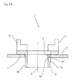
- the composite of the receiving body according to
FIG. 3a along the section line IIIb-IIIb, - FIG. 4a
- one of the receiving body according to
FIG. 1 with a different base as a locking device and two anti-rotation, in side view, - FIG. 4b
- one of the receiving body according to
FIG. 1 with a different attachment or locking device, - FIG. 5
- a further embodiment of a receiving body according to
FIG. 1 and - FIG. 6
- two moldings, with the help of a composite of receiving bodies according to
FIG. 1 can be produced.
In
In die jeweilige Aufnahmeöffnung 5 können zwei gegenüberliegende Schlitze 16 vorgesehen sein, die mit dem Aufnahmekörper 2, wie dies nachfolgend noch näher erläutert ist, zusammenwirken.In the
Der jeweilige Aufnahmekörper 2, und dies ist insbesondere den
Zur Befestigung des Aufnahmekörpers 2 sind in dem Boden 7, und zwar gegenüberliegend zu dem Bereich von dem die Haltefinger 9 abstehen, ein Sockel 10 angeformt, der im Wesentlichen eine in drei Abschnitten unterteilte Mantelfläche aufweist.For fixing the receiving
Gemäß
Desweiteren besteht die Außenkontur des Sockels 10 aus einem V-förmig ausgestalteten Vorsprung 11 bezogen auf die Längsachse 8 des Aufnahmekörpers 2, die demnach einen ersten und zweiten Schenkel 12, 13 aufweist. Die in Richtung des freien Endes des Sockels 10 weisenden Schenkel 14 des Sockels 10 ist dabei kleiner bemessen als die dem Gitterblech oder der Trägerplatte 3 zugewandten Schenkel 13 im montierten bzw. eingesteckten Zustand des Aufnahmekörpers 2 an der Trägerplatte 3.Furthermore, the outer contour of the
Insbesondere aus
Der dritte Teilabschnitt des Sockels 10 verläuft unmittelbar benachbart zu der Unterseite der Trägerplatte 3 und ist dem zweiten Sockel 12 zuzuordnen. Dabei ist wesentlich, dass die benachbart zu dem Sockel 10 verlaufende Schrägfläche des Schenkels 13 von innen nach außen ansteigt und etwa im Bereich des Randes der Aufnahmeöffnung 5 von innen nach außen abfällt. Durch diese gewinkelte Struktur des Schenkels 13 des Sockels 10 ist nämlich erreicht, dass der Aufnahmekörper 2 zuverlässig an der Trägerplatte 3 fixiert ist, ohne dass der Aufnahmekörper 2 wackelt oder verdreht werden kann.The third section of the
Aufgrund der Ausgestaltung des Sockels 10 an dem somit mindestens zwei gegenüberliegende Vorsprünge 11 angeformt sind, die die V-förmige Außenkontur aufweisen und folglich einen ersten und einen zweiten Schenkel 13, 14 bilden, durch die der Außenumfang des Sockels 10 in Längsrichtung 8 von unten nach oben zunächst vergrößert und ab einem bestimmten Abschnitt verkleinert ist, kann der Sockel 10 in die jeweilige Aufnahmeöffnung 5 eingesteckt und in dieser arretiert sein.Due to the configuration of the base 10 on which thus at least two
Durch diese Ausgestaltung des Sockels 10 entstehen keine Hinterschneidungen, so dass bei der Herstellung solcher Aufnahmekörper 2 ein Verbund mit einer beliebigen Anzahl und in einer beliebigen Richtung herstellbar sind. Gemäß
In den
In
Die Rastfüße 10' gehen übergangslos in die Haltefinger 9 über und bilden demnach eine gemeinsame Baueinheit. Zwischen den Rastfüßen 10' bzw. den Haltefingern 9 können Stützrippen 20 vorgesehen sein, durch die die benachbarten Rastfüße 10' bzw. die Haltefinger 9 gegenseitig abgestützt sind, um den Aufnahmekörper 2 zu versteifen.The locking feet 10 'merge seamlessly into the retaining
Der Vorsprung 11 ist zwar in den gezeigten Ausführungsvarianten der
Claims (11)
dass mindestens vier der Aufnahmekörper (2) gemeinsam in einem Spritzgussverfahren hergestellt sind, dass der derart geschaffene Verbund von Aufnahmekörper (2) eine Baueinheit bildet, dass mindestens einer der Sockel (10) an dem Verbund der Aufnahmekörper (2) vorgesehen ist, dass die Querschnittskontur der jeweiligen Sockel (10) in Längsrichtung des Aufnahmekörpers (2) L- oder V-förmig ausgestaltet ist, oder dass an dem Sockel (10) ein L- oder V-förmiger Vorsprung (11) angeformt ist.Receiving body (2) for holding isolated objects (6), for example of workpieces, for their processing and transport, consisting of
in that at least four of the receiving bodies (2) are manufactured together in an injection molding process such that the composite of receiving body (2) created in this way forms an assembly that at least one of the bases (10) is provided on the composite of the receiving bodies (2) Cross-sectional contour of the respective base (10) in the longitudinal direction of the receiving body (2) L- or V-shaped configuration, or that on the base (10) an L- or V-shaped projection (11) is integrally formed.
dadurch gekennzeichnet,
dass an dem Verbund der Aufnahmekörper (2) mindestens eine Verdrehsicherung (15) vorgesehen oder angearbeitet ist, durch die der Verbund der Aufnahmekörper (2) lageorientiert in einer Trägerplatte (3) oder gehalten ist.A receiving body according to claim 1,
characterized,
in that at least one anti-twist device (15) is provided or worked on the composite of the receiving body (2), by means of which the composite of the receiving body (2) is oriented or held in a carrier plate (3).
dadurch gekennzeichnet,
dass der Vorsprung (11) als Teilring-Segment mit einem Öffnungswinkel von 1° bis 20° ausgestaltet ist.A receiving body according to claim 1 or 2,
characterized,
that the projection (11) is designed as a partial ring segment with an opening angle of 1 ° to 20 °.
dadurch gekennzeichnet,
dass der der Trägerplatte (3) im montierten Zustand zugewandte Schenkel (13) der Vorsprünge (11) eine gewinkelte, gekrümmte oder gebogene Oberfläche aufweist, die in Richtung des Sockels (10) abfällt und in Richtung des Außenumfangs des Vorsprungs (11) abfällt.Housing according to one of the preceding claims,
characterized,
in that the leg (13) of the projections (11) facing the carrier plate (3) in the assembled state has an angled, curved or curved surface which drops in the direction of the base (10) and falls in the direction of the outer circumference of the projection (11).
dadurch gekennzeichnet,
dass der Boden (7) den Außenumfang des Sockels (10) überragt und dass zwischen dem Boden (7) und dem Vorsprung (11) ein zylinderförmiger Einschnitt (18) vorgesehen ist.Housing according to one of the preceding claims,
characterized,
in that the base (7) projects beyond the outer circumference of the base (10) and in that a cylindrical recess (18) is provided between the base (7) and the projection (11).
dadurch gekennzeichnet,
dass der Außendurchmesser des Einschnitts (18) etwas kleiner oder gleichgroß bemessen ist wie der Innendurchmesser der Aufnahmeöffnung (5) bzw. dass die Außenkontur des Einschnitts (18) an die Innenkontur der Aufnahmeöffnung (5) angepasst ist.A receiving body according to claim 5,
characterized,
that the outer diameter of the incision (18) is slightly smaller or of equal size as the inner diameter of the receiving opening (5) and that the outer contour of the recess (18) to the inner contour of the receiving opening (5) is adapted.
dadurch gekennzeichnet,
dass der Sockel (10) aus vier voneinander beabstandeten und parallel zu der Längsrichtung (8) des Aufnahmekörpers (2) ausgerichteten Rastfüßen (10') gebildet ist.Housing according to one of the preceding claims,
characterized,
in that the base (10) is formed from four latching feet (10 ') which are spaced apart and aligned parallel to the longitudinal direction (8) of the receiving body (2).
dadurch gekennzeichnet,
dass an zwei Rastfüßen (10') einer der Vorsprünge (11) angeformt ist und dass an den beiden anderen Rastfüßen (10') ein dazu gegenüberliegender Vorsprung (19) vorgesehen ist.A receiving body according to claim 7,
characterized,
in that one of the projections (11) is integrally formed on two latching feet (10 ') and that an opposing projection (19) is provided on the other two latching feet (10').
dadurch gekennzeichnet,
dass der Abstand von zwei gegenüberliegenden Vorsprüngen (11 und 19) derart bemessen ist, dass beide an der ober- bzw. Unterseite der Trägerplatte (3) im montierten Zustand des Aufnahmekörpers (2) an diesen anliegen.A receiving body according to claim 8,
characterized,
that the spacing of two opposite projections (11 and 19) is dimensioned such that both at the top and bottom of the carrier plate (3) applied to these in the assembled state of the receiving body (2).
dadurch gekennzeichnet,
dass zwischen zwei benachbarten Rastfüßen (11') mindestens eine Stützrippe (20) angeformt ist.A receiving body according to any one of claims 7 to 9,
characterized,
that between two adjacent locking feet (11 ') at least one support rib (20) is integrally formed.
dadurch gekennzeichnet,
dass die Rastfüße (10') in die Haltefinger (9) übergehen.A receiving body according to claim 9 or 10,
characterized,
that the locking feet (10 ') pass into the retaining fingers (9).
Priority Applications (2)
| Application Number | Priority Date | Filing Date | Title |
|---|---|---|---|
| EP14170882.6A EP2952439B1 (en) | 2014-06-03 | 2014-06-03 | Carrier assembly |
| EP15166236.8A EP2952440B1 (en) | 2014-06-03 | 2015-05-04 | Receiving body, holding device comprising receiving bodies and device comprising groups of receiving bodies |
Applications Claiming Priority (1)
| Application Number | Priority Date | Filing Date | Title |
|---|---|---|---|
| EP14170882.6A EP2952439B1 (en) | 2014-06-03 | 2014-06-03 | Carrier assembly |
Publications (2)
| Publication Number | Publication Date |
|---|---|
| EP2952439A1 true EP2952439A1 (en) | 2015-12-09 |
| EP2952439B1 EP2952439B1 (en) | 2016-08-24 |
Family
ID=50884717
Family Applications (2)
| Application Number | Title | Priority Date | Filing Date |
|---|---|---|---|
| EP14170882.6A Active EP2952439B1 (en) | 2014-06-03 | 2014-06-03 | Carrier assembly |
| EP15166236.8A Active EP2952440B1 (en) | 2014-06-03 | 2015-05-04 | Receiving body, holding device comprising receiving bodies and device comprising groups of receiving bodies |
Family Applications After (1)
| Application Number | Title | Priority Date | Filing Date |
|---|---|---|---|
| EP15166236.8A Active EP2952440B1 (en) | 2014-06-03 | 2015-05-04 | Receiving body, holding device comprising receiving bodies and device comprising groups of receiving bodies |
Country Status (1)
| Country | Link |
|---|---|
| EP (2) | EP2952439B1 (en) |
Cited By (8)
| Publication number | Priority date | Publication date | Assignee | Title |
|---|---|---|---|---|
| EP3434611A2 (en) | 2017-07-28 | 2019-01-30 | Ferremi Luca Srl a Socio Unico | Piece holding system for industrial use |
| CN112996729A (en) * | 2018-05-08 | 2021-06-18 | 林志隆 | Separator and separator plate |
| DE102019135183A1 (en) * | 2019-12-19 | 2021-06-24 | Oerlikon Surface Solutions Ag, Pfäffikon | Holding system for holding substrates |
| USD945735S1 (en) | 2019-05-15 | 2022-03-08 | Chep Technology Pty Limited | Part for a pallet |
| USD949509S1 (en) | 2019-05-15 | 2022-04-19 | Chep Technology Pty Limited | Part for a pallet |
| USD951580S1 (en) | 2019-05-15 | 2022-05-10 | Chep Technology Pty Limited | Part for a pallet |
| US11542062B2 (en) | 2017-11-16 | 2023-01-03 | Chep Technology Pty Limited | Pallet with support modules |
| WO2023104979A1 (en) * | 2021-12-08 | 2023-06-15 | Zell Systemtechnik Gmbh | Workpiece support |
Families Citing this family (1)
| Publication number | Priority date | Publication date | Assignee | Title |
|---|---|---|---|---|
| CN109367968A (en) * | 2018-12-05 | 2019-02-22 | 盐城远大金属科技有限公司 | A kind of cam special tooling |
Citations (3)
| Publication number | Priority date | Publication date | Assignee | Title |
|---|---|---|---|---|
| DE202012103711U1 (en) * | 2012-09-27 | 2012-11-15 | Ingo Zell | Support plate of a workpiece carrier system and workpiece carrier system |
| EP2570234A1 (en) * | 2011-09-13 | 2013-03-20 | Alwa GmbH Konstruktion & Formenbau | Carrier |
| EP2687454A1 (en) * | 2012-07-17 | 2014-01-22 | ALWA GmbH & Co. KG Konstruktion & Formenbau | Device for stacking at least two carrier plates |
Family Cites Families (4)
| Publication number | Priority date | Publication date | Assignee | Title |
|---|---|---|---|---|
| FR1365477A (en) * | 1963-05-22 | 1964-07-03 | Vitherm | Advanced bottle rack |
| US5660279A (en) * | 1992-07-29 | 1997-08-26 | Rehrig Pacific Company, Inc. | Stackable low depth bottle case |
| DE102012020591A1 (en) * | 2012-10-22 | 2014-04-24 | Fischer-Draht Gmbh | Workpiece carrier e.g. pallet used in industrial sectors for storage of workpiece, has workpiece receiving portion that is held on mounting interface of base portion, by pivoting rotary latch of locking device below base portion |
| EP2810887A1 (en) * | 2013-06-05 | 2014-12-10 | ALWA GmbH & Co. KG Konstruktion & Formenbau | Device for receiving and holding objects and transport device |
-
2014
- 2014-06-03 EP EP14170882.6A patent/EP2952439B1/en active Active
-
2015
- 2015-05-04 EP EP15166236.8A patent/EP2952440B1/en active Active
Patent Citations (4)
| Publication number | Priority date | Publication date | Assignee | Title |
|---|---|---|---|---|
| EP2570234A1 (en) * | 2011-09-13 | 2013-03-20 | Alwa GmbH Konstruktion & Formenbau | Carrier |
| EP2570234B1 (en) | 2011-09-13 | 2013-11-20 | ALWA GmbH & Co. KG Konstruktion & Formenbau | Carrier |
| EP2687454A1 (en) * | 2012-07-17 | 2014-01-22 | ALWA GmbH & Co. KG Konstruktion & Formenbau | Device for stacking at least two carrier plates |
| DE202012103711U1 (en) * | 2012-09-27 | 2012-11-15 | Ingo Zell | Support plate of a workpiece carrier system and workpiece carrier system |
Cited By (12)
| Publication number | Priority date | Publication date | Assignee | Title |
|---|---|---|---|---|
| EP3434611A2 (en) | 2017-07-28 | 2019-01-30 | Ferremi Luca Srl a Socio Unico | Piece holding system for industrial use |
| US11542062B2 (en) | 2017-11-16 | 2023-01-03 | Chep Technology Pty Limited | Pallet with support modules |
| US11912462B2 (en) | 2017-11-16 | 2024-02-27 | Chep Technology Pty Limited | Support module |
| CN112996729A (en) * | 2018-05-08 | 2021-06-18 | 林志隆 | Separator and separator plate |
| US20210229866A1 (en) * | 2018-05-08 | 2021-07-29 | Choon Sen David Lam | A divider and divider plate |
| EP3814241A4 (en) * | 2018-05-08 | 2022-01-19 | Liew, Yat Fang | A divider and divider plate |
| US11952171B2 (en) * | 2018-05-08 | 2024-04-09 | Yat Fang Liew | Divider and divider plate |
| USD945735S1 (en) | 2019-05-15 | 2022-03-08 | Chep Technology Pty Limited | Part for a pallet |
| USD949509S1 (en) | 2019-05-15 | 2022-04-19 | Chep Technology Pty Limited | Part for a pallet |
| USD951580S1 (en) | 2019-05-15 | 2022-05-10 | Chep Technology Pty Limited | Part for a pallet |
| DE102019135183A1 (en) * | 2019-12-19 | 2021-06-24 | Oerlikon Surface Solutions Ag, Pfäffikon | Holding system for holding substrates |
| WO2023104979A1 (en) * | 2021-12-08 | 2023-06-15 | Zell Systemtechnik Gmbh | Workpiece support |
Also Published As
| Publication number | Publication date |
|---|---|
| EP2952440A1 (en) | 2015-12-09 |
| EP2952440B1 (en) | 2017-07-19 |
| EP2952439B1 (en) | 2016-08-24 |
Similar Documents
| Publication | Publication Date | Title |
|---|---|---|
| EP2952439B1 (en) | Carrier assembly | |
| EP3124391B1 (en) | Support assembly | |
| EP2860127B1 (en) | Device for holding objects and corresponding connecting device | |
| EP2860126B1 (en) | Device for holding objects and corresponding connecting device | |
| EP3330196B1 (en) | Device for receiving objects and corresponding connector | |
| EP2965998B1 (en) | Support plate | |
| EP2546528A1 (en) | Wall ring for an axial ventilator | |
| EP2570234B1 (en) | Carrier | |
| DE2346154A1 (en) | PREFABRICATED CONNECTING ELEMENT WITH SCREW AND WASHER AND PROCESS FOR ITS MANUFACTURING | |
| EP2588766B1 (en) | Fastening device | |
| EP2930289A1 (en) | Locking cylinder and installation device | |
| DE102006030769B3 (en) | Motor vehicle jack accommodating device, has set of locking sections deformed in area of another set of sections, where former set of sections locks latter set of sections when bolt is moved from releasing into locking position | |
| EP3473496A1 (en) | Holding device and assembly comprising a holding device | |
| EP3508737A1 (en) | Connection assembly for headlamp components | |
| EP2660411A2 (en) | Key bow cover | |
| WO2017037247A1 (en) | Closure unit for an air passage | |
| EP3045617B1 (en) | Rosette and assembly of a door or window handle and a rosette on a receiving opening of a door leaf, a window leaf or the like | |
| EP3067495B1 (en) | Holder element of a fitting part of an espagnolette fitting | |
| DE102016115548B4 (en) | Indexed rotary switch | |
| DE202011109215U1 (en) | Basket coil for wire, in particular for welding wire | |
| EP2690729A1 (en) | Electrical installation system and dry wall box for electric installation | |
| EP2821285B1 (en) | Connecting element for fastening trims on a bumper | |
| DE102012011023A1 (en) | Object retention system | |
| EP2486827A1 (en) | Spring element | |
| EP3470689B1 (en) | Fixing device and method for mounting a sensor in an opening |
Legal Events
| Date | Code | Title | Description |
|---|---|---|---|
| PUAI | Public reference made under article 153(3) epc to a published international application that has entered the european phase |
Free format text: ORIGINAL CODE: 0009012 |
|
| 17P | Request for examination filed |
Effective date: 20150122 |
|
| AK | Designated contracting states |
Kind code of ref document: A1 Designated state(s): AL AT BE BG CH CY CZ DE DK EE ES FI FR GB GR HR HU IE IS IT LI LT LU LV MC MK MT NL NO PL PT RO RS SE SI SK SM TR |
|
| AX | Request for extension of the european patent |
Extension state: BA ME |
|
| GRAP | Despatch of communication of intention to grant a patent |
Free format text: ORIGINAL CODE: EPIDOSNIGR1 |
|
| RIC1 | Information provided on ipc code assigned before grant |
Ipc: B65D 19/44 20060101AFI20151215BHEP Ipc: B23Q 7/14 20060101ALN20151215BHEP Ipc: B65D 19/38 20060101ALN20151215BHEP |
|
| INTG | Intention to grant announced |
Effective date: 20160108 |
|
| GRAS | Grant fee paid |
Free format text: ORIGINAL CODE: EPIDOSNIGR3 |
|
| GRAA | (expected) grant |
Free format text: ORIGINAL CODE: 0009210 |
|
| AK | Designated contracting states |
Kind code of ref document: B1 Designated state(s): AL AT BE BG CH CY CZ DE DK EE ES FI FR GB GR HR HU IE IS IT LI LT LU LV MC MK MT NL NO PL PT RO RS SE SI SK SM TR |
|
| REG | Reference to a national code |
Ref country code: GB Ref legal event code: FG4D Free format text: NOT ENGLISH |
|
| REG | Reference to a national code |
Ref country code: CH Ref legal event code: EP |
|
| REG | Reference to a national code |
Ref country code: AT Ref legal event code: REF Ref document number: 822833 Country of ref document: AT Kind code of ref document: T Effective date: 20160915 |
|
| REG | Reference to a national code |
Ref country code: IE Ref legal event code: FG4D Free format text: LANGUAGE OF EP DOCUMENT: GERMAN |
|
| REG | Reference to a national code |
Ref country code: DE Ref legal event code: R096 Ref document number: 502014001296 Country of ref document: DE |
|
| REG | Reference to a national code |
Ref country code: LT Ref legal event code: MG4D |
|
| REG | Reference to a national code |
Ref country code: NL Ref legal event code: MP Effective date: 20160824 |
|
| PG25 | Lapsed in a contracting state [announced via postgrant information from national office to epo] |
Ref country code: HR Free format text: LAPSE BECAUSE OF FAILURE TO SUBMIT A TRANSLATION OF THE DESCRIPTION OR TO PAY THE FEE WITHIN THE PRESCRIBED TIME-LIMIT Effective date: 20160824 Ref country code: RS Free format text: LAPSE BECAUSE OF FAILURE TO SUBMIT A TRANSLATION OF THE DESCRIPTION OR TO PAY THE FEE WITHIN THE PRESCRIBED TIME-LIMIT Effective date: 20160824 Ref country code: NL Free format text: LAPSE BECAUSE OF FAILURE TO SUBMIT A TRANSLATION OF THE DESCRIPTION OR TO PAY THE FEE WITHIN THE PRESCRIBED TIME-LIMIT Effective date: 20160824 Ref country code: FI Free format text: LAPSE BECAUSE OF FAILURE TO SUBMIT A TRANSLATION OF THE DESCRIPTION OR TO PAY THE FEE WITHIN THE PRESCRIBED TIME-LIMIT Effective date: 20160824 Ref country code: LT Free format text: LAPSE BECAUSE OF FAILURE TO SUBMIT A TRANSLATION OF THE DESCRIPTION OR TO PAY THE FEE WITHIN THE PRESCRIBED TIME-LIMIT Effective date: 20160824 Ref country code: NO Free format text: LAPSE BECAUSE OF FAILURE TO SUBMIT A TRANSLATION OF THE DESCRIPTION OR TO PAY THE FEE WITHIN THE PRESCRIBED TIME-LIMIT Effective date: 20161124 |
|
| PG25 | Lapsed in a contracting state [announced via postgrant information from national office to epo] |
Ref country code: ES Free format text: LAPSE BECAUSE OF FAILURE TO SUBMIT A TRANSLATION OF THE DESCRIPTION OR TO PAY THE FEE WITHIN THE PRESCRIBED TIME-LIMIT Effective date: 20160824 Ref country code: LV Free format text: LAPSE BECAUSE OF FAILURE TO SUBMIT A TRANSLATION OF THE DESCRIPTION OR TO PAY THE FEE WITHIN THE PRESCRIBED TIME-LIMIT Effective date: 20160824 Ref country code: SE Free format text: LAPSE BECAUSE OF FAILURE TO SUBMIT A TRANSLATION OF THE DESCRIPTION OR TO PAY THE FEE WITHIN THE PRESCRIBED TIME-LIMIT Effective date: 20160824 Ref country code: GR Free format text: LAPSE BECAUSE OF FAILURE TO SUBMIT A TRANSLATION OF THE DESCRIPTION OR TO PAY THE FEE WITHIN THE PRESCRIBED TIME-LIMIT Effective date: 20161125 Ref country code: PT Free format text: LAPSE BECAUSE OF FAILURE TO SUBMIT A TRANSLATION OF THE DESCRIPTION OR TO PAY THE FEE WITHIN THE PRESCRIBED TIME-LIMIT Effective date: 20161226 |
|
| PG25 | Lapsed in a contracting state [announced via postgrant information from national office to epo] |
Ref country code: EE Free format text: LAPSE BECAUSE OF FAILURE TO SUBMIT A TRANSLATION OF THE DESCRIPTION OR TO PAY THE FEE WITHIN THE PRESCRIBED TIME-LIMIT Effective date: 20160824 Ref country code: RO Free format text: LAPSE BECAUSE OF FAILURE TO SUBMIT A TRANSLATION OF THE DESCRIPTION OR TO PAY THE FEE WITHIN THE PRESCRIBED TIME-LIMIT Effective date: 20160824 |
|
| REG | Reference to a national code |
Ref country code: DE Ref legal event code: R097 Ref document number: 502014001296 Country of ref document: DE |
|
| PG25 | Lapsed in a contracting state [announced via postgrant information from national office to epo] |
Ref country code: SM Free format text: LAPSE BECAUSE OF FAILURE TO SUBMIT A TRANSLATION OF THE DESCRIPTION OR TO PAY THE FEE WITHIN THE PRESCRIBED TIME-LIMIT Effective date: 20160824 Ref country code: PL Free format text: LAPSE BECAUSE OF FAILURE TO SUBMIT A TRANSLATION OF THE DESCRIPTION OR TO PAY THE FEE WITHIN THE PRESCRIBED TIME-LIMIT Effective date: 20160824 Ref country code: BG Free format text: LAPSE BECAUSE OF FAILURE TO SUBMIT A TRANSLATION OF THE DESCRIPTION OR TO PAY THE FEE WITHIN THE PRESCRIBED TIME-LIMIT Effective date: 20161124 Ref country code: SK Free format text: LAPSE BECAUSE OF FAILURE TO SUBMIT A TRANSLATION OF THE DESCRIPTION OR TO PAY THE FEE WITHIN THE PRESCRIBED TIME-LIMIT Effective date: 20160824 Ref country code: CZ Free format text: LAPSE BECAUSE OF FAILURE TO SUBMIT A TRANSLATION OF THE DESCRIPTION OR TO PAY THE FEE WITHIN THE PRESCRIBED TIME-LIMIT Effective date: 20160824 Ref country code: DK Free format text: LAPSE BECAUSE OF FAILURE TO SUBMIT A TRANSLATION OF THE DESCRIPTION OR TO PAY THE FEE WITHIN THE PRESCRIBED TIME-LIMIT Effective date: 20160824 |
|
| REG | Reference to a national code |
Ref country code: FR Ref legal event code: PLFP Year of fee payment: 4 |
|
| PLBE | No opposition filed within time limit |
Free format text: ORIGINAL CODE: 0009261 |
|
| STAA | Information on the status of an ep patent application or granted ep patent |
Free format text: STATUS: NO OPPOSITION FILED WITHIN TIME LIMIT |
|
| 26N | No opposition filed |
Effective date: 20170526 |
|
| PG25 | Lapsed in a contracting state [announced via postgrant information from national office to epo] |
Ref country code: SI Free format text: LAPSE BECAUSE OF FAILURE TO SUBMIT A TRANSLATION OF THE DESCRIPTION OR TO PAY THE FEE WITHIN THE PRESCRIBED TIME-LIMIT Effective date: 20160824 |
|
| PG25 | Lapsed in a contracting state [announced via postgrant information from national office to epo] |
Ref country code: MC Free format text: LAPSE BECAUSE OF FAILURE TO SUBMIT A TRANSLATION OF THE DESCRIPTION OR TO PAY THE FEE WITHIN THE PRESCRIBED TIME-LIMIT Effective date: 20160824 |
|
| REG | Reference to a national code |
Ref country code: CH Ref legal event code: PL |
|
| REG | Reference to a national code |
Ref country code: IE Ref legal event code: MM4A |
|
| PG25 | Lapsed in a contracting state [announced via postgrant information from national office to epo] |
Ref country code: LI Free format text: LAPSE BECAUSE OF NON-PAYMENT OF DUE FEES Effective date: 20170630 Ref country code: CH Free format text: LAPSE BECAUSE OF NON-PAYMENT OF DUE FEES Effective date: 20170630 Ref country code: IE Free format text: LAPSE BECAUSE OF NON-PAYMENT OF DUE FEES Effective date: 20170603 Ref country code: LU Free format text: LAPSE BECAUSE OF NON-PAYMENT OF DUE FEES Effective date: 20170603 |
|
| REG | Reference to a national code |
Ref country code: BE Ref legal event code: MM Effective date: 20170630 |
|
| REG | Reference to a national code |
Ref country code: FR Ref legal event code: PLFP Year of fee payment: 5 |
|
| PG25 | Lapsed in a contracting state [announced via postgrant information from national office to epo] |
Ref country code: BE Free format text: LAPSE BECAUSE OF NON-PAYMENT OF DUE FEES Effective date: 20170630 |
|
| PGFP | Annual fee paid to national office [announced via postgrant information from national office to epo] |
Ref country code: FR Payment date: 20180625 Year of fee payment: 5 |
|
| PG25 | Lapsed in a contracting state [announced via postgrant information from national office to epo] |
Ref country code: MT Free format text: LAPSE BECAUSE OF FAILURE TO SUBMIT A TRANSLATION OF THE DESCRIPTION OR TO PAY THE FEE WITHIN THE PRESCRIBED TIME-LIMIT Effective date: 20160824 |
|
| PG25 | Lapsed in a contracting state [announced via postgrant information from national office to epo] |
Ref country code: AL Free format text: LAPSE BECAUSE OF FAILURE TO SUBMIT A TRANSLATION OF THE DESCRIPTION OR TO PAY THE FEE WITHIN THE PRESCRIBED TIME-LIMIT Effective date: 20160824 |
|
| PGFP | Annual fee paid to national office [announced via postgrant information from national office to epo] |
Ref country code: IT Payment date: 20180622 Year of fee payment: 5 |
|
| GBPC | Gb: european patent ceased through non-payment of renewal fee |
Effective date: 20180603 |
|
| PG25 | Lapsed in a contracting state [announced via postgrant information from national office to epo] |
Ref country code: GB Free format text: LAPSE BECAUSE OF NON-PAYMENT OF DUE FEES Effective date: 20180603 |
|
| PG25 | Lapsed in a contracting state [announced via postgrant information from national office to epo] |
Ref country code: HU Free format text: LAPSE BECAUSE OF FAILURE TO SUBMIT A TRANSLATION OF THE DESCRIPTION OR TO PAY THE FEE WITHIN THE PRESCRIBED TIME-LIMIT; INVALID AB INITIO Effective date: 20140603 |
|
| PG25 | Lapsed in a contracting state [announced via postgrant information from national office to epo] |
Ref country code: CY Free format text: LAPSE BECAUSE OF FAILURE TO SUBMIT A TRANSLATION OF THE DESCRIPTION OR TO PAY THE FEE WITHIN THE PRESCRIBED TIME-LIMIT Effective date: 20160824 |
|
| PG25 | Lapsed in a contracting state [announced via postgrant information from national office to epo] |
Ref country code: MK Free format text: LAPSE BECAUSE OF FAILURE TO SUBMIT A TRANSLATION OF THE DESCRIPTION OR TO PAY THE FEE WITHIN THE PRESCRIBED TIME-LIMIT Effective date: 20160824 |
|
| PG25 | Lapsed in a contracting state [announced via postgrant information from national office to epo] |
Ref country code: TR Free format text: LAPSE BECAUSE OF FAILURE TO SUBMIT A TRANSLATION OF THE DESCRIPTION OR TO PAY THE FEE WITHIN THE PRESCRIBED TIME-LIMIT Effective date: 20160824 |
|
| PG25 | Lapsed in a contracting state [announced via postgrant information from national office to epo] |
Ref country code: IT Free format text: LAPSE BECAUSE OF NON-PAYMENT OF DUE FEES Effective date: 20190603 |
|
| PG25 | Lapsed in a contracting state [announced via postgrant information from national office to epo] |
Ref country code: FR Free format text: LAPSE BECAUSE OF NON-PAYMENT OF DUE FEES Effective date: 20190630 |
|
| PG25 | Lapsed in a contracting state [announced via postgrant information from national office to epo] |
Ref country code: IS Free format text: LAPSE BECAUSE OF FAILURE TO SUBMIT A TRANSLATION OF THE DESCRIPTION OR TO PAY THE FEE WITHIN THE PRESCRIBED TIME-LIMIT Effective date: 20161224 |
|
| REG | Reference to a national code |
Ref country code: AT Ref legal event code: MM01 Ref document number: 822833 Country of ref document: AT Kind code of ref document: T Effective date: 20190603 |
|
| PG25 | Lapsed in a contracting state [announced via postgrant information from national office to epo] |
Ref country code: AT Free format text: LAPSE BECAUSE OF NON-PAYMENT OF DUE FEES Effective date: 20190603 |
|
| REG | Reference to a national code |
Ref country code: DE Ref legal event code: R082 Ref document number: 502014001296 Country of ref document: DE Representative=s name: GEITZ PATENTANWAELTE PARTG MBB, DE Ref country code: DE Ref legal event code: R082 Ref document number: 502014001296 Country of ref document: DE Representative=s name: GEITZ TRUCKENMUELLER LUCHT CHRIST PATENTANWAEL, DE |
|
| P01 | Opt-out of the competence of the unified patent court (upc) registered |
Effective date: 20230512 |
|
| PGFP | Annual fee paid to national office [announced via postgrant information from national office to epo] |
Ref country code: DE Payment date: 20230620 Year of fee payment: 10 |