EP2570234A1 - Carrier - Google Patents
Carrier Download PDFInfo
- Publication number
- EP2570234A1 EP2570234A1 EP11181000A EP11181000A EP2570234A1 EP 2570234 A1 EP2570234 A1 EP 2570234A1 EP 11181000 A EP11181000 A EP 11181000A EP 11181000 A EP11181000 A EP 11181000A EP 2570234 A1 EP2570234 A1 EP 2570234A1
- Authority
- EP
- European Patent Office
- Prior art keywords
- recording medium
- medium according
- retaining
- fingers
- holding
- Prior art date
- Legal status (The legal status is an assumption and is not a legal conclusion. Google has not performed a legal analysis and makes no representation as to the accuracy of the status listed.)
- Granted
Links
- 239000004033 plastic Substances 0.000 claims abstract description 5
- 229920003023 plastic Polymers 0.000 claims abstract description 5
- 238000001746 injection moulding Methods 0.000 claims abstract description 4
- 239000000463 material Substances 0.000 claims abstract description 4
- 239000000969 carrier Substances 0.000 claims description 4
- 238000012545 processing Methods 0.000 claims description 4
- 238000000465 moulding Methods 0.000 claims 1
- 238000004140 cleaning Methods 0.000 description 10
- 239000011248 coating agent Substances 0.000 description 8
- 239000012459 cleaning agent Substances 0.000 description 7
- 238000000576 coating method Methods 0.000 description 3
- 238000003780 insertion Methods 0.000 description 3
- 230000037431 insertion Effects 0.000 description 3
- 238000013461 design Methods 0.000 description 2
- 238000011161 development Methods 0.000 description 2
- 230000018109 developmental process Effects 0.000 description 2
- 238000004519 manufacturing process Methods 0.000 description 2
- 238000000034 method Methods 0.000 description 2
- 230000008719 thickening Effects 0.000 description 2
- 230000001419 dependent effect Effects 0.000 description 1
- 230000005484 gravity Effects 0.000 description 1
- 238000002347 injection Methods 0.000 description 1
- 239000007924 injection Substances 0.000 description 1
- 238000003754 machining Methods 0.000 description 1
- 239000002245 particle Substances 0.000 description 1
- 239000002689 soil Substances 0.000 description 1
- 230000000087 stabilizing effect Effects 0.000 description 1
- 229910001220 stainless steel Inorganic materials 0.000 description 1
- 239000010935 stainless steel Substances 0.000 description 1
Images


Classifications
-
- B—PERFORMING OPERATIONS; TRANSPORTING
- B65—CONVEYING; PACKING; STORING; HANDLING THIN OR FILAMENTARY MATERIAL
- B65D—CONTAINERS FOR STORAGE OR TRANSPORT OF ARTICLES OR MATERIALS, e.g. BAGS, BARRELS, BOTTLES, BOXES, CANS, CARTONS, CRATES, DRUMS, JARS, TANKS, HOPPERS, FORWARDING CONTAINERS; ACCESSORIES, CLOSURES, OR FITTINGS THEREFOR; PACKAGING ELEMENTS; PACKAGES
- B65D19/00—Pallets or like platforms, with or without side walls, for supporting loads to be lifted or lowered
- B65D19/0002—Platforms, i.e. load supporting devices without provision for handling by a forklift
-
- B—PERFORMING OPERATIONS; TRANSPORTING
- B65—CONVEYING; PACKING; STORING; HANDLING THIN OR FILAMENTARY MATERIAL
- B65D—CONTAINERS FOR STORAGE OR TRANSPORT OF ARTICLES OR MATERIALS, e.g. BAGS, BARRELS, BOTTLES, BOXES, CANS, CARTONS, CRATES, DRUMS, JARS, TANKS, HOPPERS, FORWARDING CONTAINERS; ACCESSORIES, CLOSURES, OR FITTINGS THEREFOR; PACKAGING ELEMENTS; PACKAGES
- B65D19/00—Pallets or like platforms, with or without side walls, for supporting loads to be lifted or lowered
- B65D19/38—Details or accessories
- B65D19/44—Elements or devices for locating articles on platforms
-
- B—PERFORMING OPERATIONS; TRANSPORTING
- B65—CONVEYING; PACKING; STORING; HANDLING THIN OR FILAMENTARY MATERIAL
- B65D—CONTAINERS FOR STORAGE OR TRANSPORT OF ARTICLES OR MATERIALS, e.g. BAGS, BARRELS, BOTTLES, BOXES, CANS, CARTONS, CRATES, DRUMS, JARS, TANKS, HOPPERS, FORWARDING CONTAINERS; ACCESSORIES, CLOSURES, OR FITTINGS THEREFOR; PACKAGING ELEMENTS; PACKAGES
- B65D2519/00—Pallets or like platforms, with or without side walls, for supporting loads to be lifted or lowered
- B65D2519/00004—Details relating to pallets
- B65D2519/00009—Materials
- B65D2519/00014—Materials for the load supporting surface
- B65D2519/00024—Metal
-
- B—PERFORMING OPERATIONS; TRANSPORTING
- B65—CONVEYING; PACKING; STORING; HANDLING THIN OR FILAMENTARY MATERIAL
- B65D—CONTAINERS FOR STORAGE OR TRANSPORT OF ARTICLES OR MATERIALS, e.g. BAGS, BARRELS, BOTTLES, BOXES, CANS, CARTONS, CRATES, DRUMS, JARS, TANKS, HOPPERS, FORWARDING CONTAINERS; ACCESSORIES, CLOSURES, OR FITTINGS THEREFOR; PACKAGING ELEMENTS; PACKAGES
- B65D2519/00—Pallets or like platforms, with or without side walls, for supporting loads to be lifted or lowered
- B65D2519/00004—Details relating to pallets
- B65D2519/00009—Materials
- B65D2519/00049—Materials for the base surface
- B65D2519/00059—Metal
-
- B—PERFORMING OPERATIONS; TRANSPORTING
- B65—CONVEYING; PACKING; STORING; HANDLING THIN OR FILAMENTARY MATERIAL
- B65D—CONTAINERS FOR STORAGE OR TRANSPORT OF ARTICLES OR MATERIALS, e.g. BAGS, BARRELS, BOTTLES, BOXES, CANS, CARTONS, CRATES, DRUMS, JARS, TANKS, HOPPERS, FORWARDING CONTAINERS; ACCESSORIES, CLOSURES, OR FITTINGS THEREFOR; PACKAGING ELEMENTS; PACKAGES
- B65D2519/00—Pallets or like platforms, with or without side walls, for supporting loads to be lifted or lowered
- B65D2519/00004—Details relating to pallets
- B65D2519/00258—Overall construction
- B65D2519/00263—Overall construction of the pallet
- B65D2519/00268—Overall construction of the pallet made of one piece
-
- B—PERFORMING OPERATIONS; TRANSPORTING
- B65—CONVEYING; PACKING; STORING; HANDLING THIN OR FILAMENTARY MATERIAL
- B65D—CONTAINERS FOR STORAGE OR TRANSPORT OF ARTICLES OR MATERIALS, e.g. BAGS, BARRELS, BOTTLES, BOXES, CANS, CARTONS, CRATES, DRUMS, JARS, TANKS, HOPPERS, FORWARDING CONTAINERS; ACCESSORIES, CLOSURES, OR FITTINGS THEREFOR; PACKAGING ELEMENTS; PACKAGES
- B65D2519/00—Pallets or like platforms, with or without side walls, for supporting loads to be lifted or lowered
- B65D2519/00004—Details relating to pallets
- B65D2519/00258—Overall construction
- B65D2519/00283—Overall construction of the load supporting surface
- B65D2519/00288—Overall construction of the load supporting surface made of one piece
-
- B—PERFORMING OPERATIONS; TRANSPORTING
- B65—CONVEYING; PACKING; STORING; HANDLING THIN OR FILAMENTARY MATERIAL
- B65D—CONTAINERS FOR STORAGE OR TRANSPORT OF ARTICLES OR MATERIALS, e.g. BAGS, BARRELS, BOTTLES, BOXES, CANS, CARTONS, CRATES, DRUMS, JARS, TANKS, HOPPERS, FORWARDING CONTAINERS; ACCESSORIES, CLOSURES, OR FITTINGS THEREFOR; PACKAGING ELEMENTS; PACKAGES
- B65D2519/00—Pallets or like platforms, with or without side walls, for supporting loads to be lifted or lowered
- B65D2519/00004—Details relating to pallets
- B65D2519/00258—Overall construction
- B65D2519/00283—Overall construction of the load supporting surface
- B65D2519/00308—Overall construction of the load supporting surface grid type, e.g. perforated plate
-
- B—PERFORMING OPERATIONS; TRANSPORTING
- B65—CONVEYING; PACKING; STORING; HANDLING THIN OR FILAMENTARY MATERIAL
- B65D—CONTAINERS FOR STORAGE OR TRANSPORT OF ARTICLES OR MATERIALS, e.g. BAGS, BARRELS, BOTTLES, BOXES, CANS, CARTONS, CRATES, DRUMS, JARS, TANKS, HOPPERS, FORWARDING CONTAINERS; ACCESSORIES, CLOSURES, OR FITTINGS THEREFOR; PACKAGING ELEMENTS; PACKAGES
- B65D2519/00—Pallets or like platforms, with or without side walls, for supporting loads to be lifted or lowered
- B65D2519/00004—Details relating to pallets
- B65D2519/00258—Overall construction
- B65D2519/00313—Overall construction of the base surface
- B65D2519/00318—Overall construction of the base surface made of one piece
-
- B—PERFORMING OPERATIONS; TRANSPORTING
- B65—CONVEYING; PACKING; STORING; HANDLING THIN OR FILAMENTARY MATERIAL
- B65D—CONTAINERS FOR STORAGE OR TRANSPORT OF ARTICLES OR MATERIALS, e.g. BAGS, BARRELS, BOTTLES, BOXES, CANS, CARTONS, CRATES, DRUMS, JARS, TANKS, HOPPERS, FORWARDING CONTAINERS; ACCESSORIES, CLOSURES, OR FITTINGS THEREFOR; PACKAGING ELEMENTS; PACKAGES
- B65D2519/00—Pallets or like platforms, with or without side walls, for supporting loads to be lifted or lowered
- B65D2519/00004—Details relating to pallets
- B65D2519/00258—Overall construction
- B65D2519/00313—Overall construction of the base surface
- B65D2519/00328—Overall construction of the base surface shape of the contact surface of the base
- B65D2519/00343—Overall construction of the base surface shape of the contact surface of the base contact surface being substantially in the form of a panel
-
- B—PERFORMING OPERATIONS; TRANSPORTING
- B65—CONVEYING; PACKING; STORING; HANDLING THIN OR FILAMENTARY MATERIAL
- B65D—CONTAINERS FOR STORAGE OR TRANSPORT OF ARTICLES OR MATERIALS, e.g. BAGS, BARRELS, BOTTLES, BOXES, CANS, CARTONS, CRATES, DRUMS, JARS, TANKS, HOPPERS, FORWARDING CONTAINERS; ACCESSORIES, CLOSURES, OR FITTINGS THEREFOR; PACKAGING ELEMENTS; PACKAGES
- B65D2519/00—Pallets or like platforms, with or without side walls, for supporting loads to be lifted or lowered
- B65D2519/00004—Details relating to pallets
- B65D2519/00736—Details
- B65D2519/0081—Elements or devices for locating articles
- B65D2519/00815—Elements or devices for locating articles on the pallet
Definitions
- the invention relates to a recording medium for holding individual workpieces for their processing and transport according to the preamble of claim 1 and 2.
- a carrier plate made of stainless steel in which a plurality of holes are incorporated with one or more radially extending grooves.
- a round Anformung is provided at the bottom of the receiving carrier, on the opposite side, on which a web spaced and parallel to the bottom.
- the Anformung can be screwed into the bore of the support plate in the manner of a bayonet catch or undercut.
- one of the receiving carriers can be fixed in each bore, so that a large number of receiving carriers can be arranged on a common carrier plate.
- the carrier plate can then be supplied together with the receiving carriers and the workpieces inserted therein a cleaning station or a coating center.
- the cleaning agent or the particles forming the coating pass through the intermediate spaces which are present between two adjacent holding fingers and the open end face opposite the bottom, into the interior and thus in the direction of the workpiece.
- the plastic material of the holding fingers and the bottom is resistant to the often aggressive cleaning and coating agents and therefore has a long service life.
- the holding fingers lose their stability and leach after a certain period of use.
- the cleaning and coating agents acting on the workpiece often exert a considerable pressure on the holding fingers, which causes them to be bent out of their initial position.
- the individual recording media are to be encompassed. This is done for example by means of robots which exert a corresponding force on the retaining fingers, so that the dimensional stability of the retaining fingers is also reduced by these processing and treatment forces.
- the holding fingers no longer assume their original position, the workpiece wobbles inside the receiving carrier and is not held reliably by it. This can lead to damage or improper coating and cleaning of the workpiece.
- a recording medium is to be made available, which can be arranged as close as possible to other recording media on a support plate, so that no unnecessary space between the adjacent recording media. Furthermore, it is an object of the invention to develop a recording medium of the type mentioned in such a way that the space enclosed by the holding fingers and the bottom space for receiving the workpiece on the outer contour is adjustable in order to adjust the volume of the space optimally to the volume of the workpiece can and to facilitate the insertion of the workpiece.
- the recording medium is thus configured in the form of a cage.
- the support ribs may be arranged in a common or in mutually different height levels. It is particularly advantageous if a plurality of support ribs are arranged concentrically on a common height level about the longitudinal axis of the receiving carrier and if a plurality of such levels spaced support ribs from the support ribs are mounted on the retaining fingers to stabilize them at several positions in their predetermined position.
- the holding fingers have an oblique or from the horizontal in the same directions inclined to each other slip planes, so that the outer contour of the hexagonal profile of the workpiece at the sliding plane in the direction of the gap, which extends between two adjacent retaining fingers, slips so that the workpiece is rotated and carried out by the rotation of the workpiece insertion of the workpiece in the recording medium, without the aid of this are to be used.
- the support ribs may be provided between the adjacent retaining fingers; However, then the support rib is to be arranged on the outer circumference of the respective retaining finger, so that the hexagon of the workpiece is not hindered by the support ribs during the slipping process.
- the recording media can be positioned adjacent to other recording media adjacent to one another on a carrier plate. Thus, no space is created between the adjacent recording media and the positioning surface provided by the carrier plate is optimally utilized.
- a rail-shaped Anformung is provided in the corner regions of the receiving carrier, which reduces the volume of the retaining fingers and the ground formed space, so that the volume of the space is optimally adapted to the workpiece inserted into this.
- the recording media can be engaged in a recess which is incorporated in the support plate in the manner of an undercut, because the locking device consists of two or more holding pillars, between each an air gap is present.
- the air gap in this case has a V-shaped or U-shaped inner contour through which the retaining fingers are pushed radially, ie in the direction of the longitudinal axis of the receiving carrier to adjust the outer periphery of the retaining pillars to the inner diameter of the recess of the support plate, so that the retaining pillars the recess in a simple way fürdrückbar and are reliably held in the recess after Verrastungsvorgang.
- the retaining pillars have a thickening from outside to inside outer contour, so that upon insertion of the receiving pillars in the recess of the support plate, the retaining pillars are compressed in the direction of the center of the soil and as soon as the retaining pillars leave the recess, spring back outward, thereby a reliable attachment of the recording medium is secured to the support plate. Accordingly, the retaining pillars can be inserted vertically from above into the recess of the carrier plate, so that the bottom can have a rectangular outer contour, because a rotation of the receiving carrier is no longer required. Consequently, the outer surfaces of the retaining fingers come into abutment with the outer surfaces of retaining fingers of the adjacent receiving carrier, so that there is no gap between them.
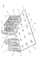
- FIG. 1 is a support plate 9 for holding rectangular recording media 1 and round recording media 1 'shown by the cleaned or coated to be cleaned workpieces 5 are isolated.
- the recording media 1 and 1 ' consist of a bottom 2 and of four perpendicular and parallel to each other holding fingers 3.
- the longitudinal axis of the respective recording medium 1 and 1' is marked by the reference numeral 3 'and corresponds substantially perpendicular to the Floor 2 protruding normals 6.
- the bottom 2 and the holding fingers 3 define a space 4, in which the workpiece 5 is inserted. Since between two adjacent retaining fingers 3, a gap 24 is provided and the bottom 2 opposite end face of the receiving carrier 1 is designed to be open, cleaning or coating agent can penetrate in the direction of the workpiece 5 through these openings.
- the workpiece 5 facing the top of the bottom 2 is provided with the reference numeral 7 and the opposite bottom of the bottom 2 by the reference numeral 8.
- a locking device 14 is mounted on the underside 8 of the bottom 2, which is explained in more detail below.
- a support rib 11 is provided between two adjacent retaining fingers 3, which run concentrically around and perpendicular to the longitudinal axis 3 'of the receiving carrier 1. It is particularly advantageous if the support ribs 11 in the region of the externally accessible openings between the retaining fingers 3, ie in the region of the free ends of the retaining fingers 3, are arranged and when the support ribs 11 run on a common height level, because this ensures that the free ends of the retaining fingers 3 are mutually supported. In order to further increase the stability of the retaining fingers 3, further support ribs 11 extending parallel to one another are provided between two adjacent retaining fingers 3. Between the support ribs 11 and the retaining fingers 3, the intermediate spaces 24 are present through which a sufficient amount of cleaning and / or coating agent enters the space 4 in the direction of the workpieces 5.
- a recess 10 is incorporated in this, in which two radially outwardly projecting grooves 12 are provided.
- the locking device 14 of the rectangular recording medium 1 consists essentially of four retaining pillars 16, which are arranged in an equally large distance from the center 15 of the bottom 2. Between the holding pillars 16, an air gap 25 is provided crosswise in each case.
- the retaining pillars 16 have a thickening from outside to inside outer contour, so that between the underside of the bottom 2 and the largest cross section of the retaining pillar 16, a contact surface 17 is created, which rests on the underside of the support plate 9 in the locked state.
- the design of the retaining pillars 16 and their operation can be seen. Namely, when the four retaining pillars 16 is pressed through the recess 10 of the support plate 9, they are thus radially compressed in the direction of the center 15, so that they slip through the recess 10. The existing air gap 25 thus allows this movement. As soon as the retaining pillars 16 with the contact surface 17 are pressed through the recess 10, the retaining pillars 16 snap back into their starting position, whereby the contact surface 17 on the underside of the support plate 9 and thereby the receiving carrier 1 is fixed to the support plate 9. The distance between the contact surface 17 and the bottom 8 of the bottom 2 is dimensioned such that the thickness of the support plate 9 coincides with this distance. To remove the recording medium 1 from the respective recess 10 is a certain, perpendicular to the top acting force required by the retaining pillars 16 are compressed by the recess 10.
- the outer contour of the bottom 2 is configured rectangular and the side lengths of the recording medium 1 are adapted to the distances of the recesses 10, a plurality of recording media 1 can be fixed without abutting each other on the support plate 9. In addition, the recording medium 1 can be latched vertically from above into the respective recess 10.
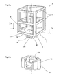
- the round receiving carrier 1 ' is provided with a locking device 14, which is in the manner of a bayonet lock in the recess 10 of the support plate 9 is used.
- a locking device 14 namely a Anformung 22 is attached to a web 19 which is parallel to the bottom 8 of the bottom 2 and spaced from this.
- the Anformung 22 and the web 19 are inserted into the recess 10 and the radially projecting grooves 12 and as soon as the web 19 is arranged on the underside of the support plate 9, the recording medium 1 'can be rotated to the aligned coincidence of the web 19 with the Groove 12 dissolve so that the web 19 comes to rest on the underside of the support plate 9 and thereby the respective recording medium 1 'is reliably fixed to the support plate 9.
- FIGS. 2b and 2c The structural design of the locking device 14 of the round receiving carrier 1 'is the FIGS. 2b and 2c refer to.
- a rail-shaped projection 13 is provided in the corner regions of the receiving carrier 1.
- the rail-shaped Anformung 13 can be injection molded in the injection molding process directly in the production of the recording medium 1 to the respective inner side of the retaining fingers 3.
- the diameter of this Anformung 13 may be configured differently sized to reduce the volume of the space 4. It is also conceivable, the Anformung 13 as a holding rail to use for a politicianschiebende rail 23.
- This rail 23 may be dimensioned to be different in size to adapt the space 4 to the outer contour of the workpiece 5 to be used.
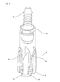
- FIG. 5 a development of the variants of a previous recording medium is shown with a round bottom 2, which is identified by the reference numeral 1 "
- the upwardly projecting retaining fingers 3 have an inclined, ie inclined, sliding plane 26 which is inclined from the horizontal and are consequently rectified Accordingly, if a workpiece 5 with a polygonal profile 27, for example a hexagon, is inserted into the receiving carrier 1 "from above, the outer edges of the polygonal profile 27 projecting outwardly from the workpiece 5 reach either the intermediate space 24 or When the polygonal profiles 27 impinge on the sliding plane 26, they slide along the sliding plane 26 in the direction of the nearest intermediate space 24.
- the polygonal profiles 27 rotate about the longitudinal axis of the workpiece 5, so that this without jamming due to Gravity in the recording carrier 1 "falls. Since the intermediate space 24 exerts no holding forces on the workpiece 5, the workpieces 5 are inserted by turning and a subsequent linear movement into the interior of the receiving carrier 1 "without aids.
- the retaining fingers 3 are bent inwards and adapted to the outer edges of the bottom 2.
- the retaining fingers 3 can also be configured rectangular.
- the slip planes 26 are inclined at an angle of 20 ° to 45 ° from the horizontal.
- the number of retaining fingers 3 is adapted to the pitch of the polygonal profile 27 of the workpiece 5, in such a way that the number of spaces 24 corresponds to the number of corners of the polygonal profile 27 or adapted thereto multiples. This means that if a hexagonal profile 27 is formed on the workpiece 5, the number of intermediate spaces 24 must be limited to six or twelve.
- FIG. 6a is a round recording medium 1'dar hire, on which only a support rib 3 is integrally formed perpendicular to the bottom 2.
- a support rib 3 is integrally formed perpendicular to the bottom 2.
- two support ribs 11 are provided, whose contour are aligned exactly aligned with the outer periphery of the bottom 2, so that the bottom 2, the retaining fingers 3 and the two attached to the retaining fingers 3 supporting ribs 11 include the space 4, in which the workpiece 5 - as already described - is used from above.
- one of the support ribs 11 is provided with an air gap 28, so that this support rib 11 is divided into two parts. It is understood that the support ribs 11 may optionally be completely closed or provided with one of the air gaps 28.
- the air gap 28 causes the aligned facing free ends of the two-part support rib 11 have a resilient property. For example, if a slightly larger sized workpiece 5 or a very soft and thus sensitive workpiece 5 is inserted into the space 4, or if the workpiece 5 is not aligned exactly aligned with the space 4, the support ribs 11 can yield without the workpiece 5 damage and at the same time it is ensured that the workpiece 5 enters the room 4.
- FIG. 6b is the recording medium 1 'provided with a rectangular, preferably square bottom 2 and integrally formed on the retaining finger 3 supporting ribs 11 are the outer contours of the bottom 2 modeled so that the support ribs 11 form a rectangular, preferably square outer and inner contour.
- the rectangular support ribs 11 can also be provided with the air gap 28 be, according to both the embodiment of the FIG. 6a as well as after FIG. 6b in alignment opposite to the one holding finger 3 extends.
Landscapes
- Engineering & Computer Science (AREA)
- Mechanical Engineering (AREA)
- Packaging For Recording Disks (AREA)
- Moulds For Moulding Plastics Or The Like (AREA)
Abstract
Description
Die Erfindung bezieht sich auf einen Aufnahmeträger zur Halterung von vereinzelten Werkstücken zu deren Bearbeitung und Transport nach dem Oberbegriff der Patentanspruches 1 und 2.The invention relates to a recording medium for holding individual workpieces for their processing and transport according to the preamble of
Es ist bekannt, diverse Werkstücke, beispielsweise Schrauben, rotations- oder nichtrotationsymmetrische Wellen, Rohre, Zapfen oder dgl., zu vereinzeln, um diese nach der spanabhebenden Bearbeitung zu reinigen, zu beschichten oder zu transportieren. Zu diesem Zweck werden insbesondere von der Kunststoffindustrie runde Körbe zur Verfügung gestellt, in die das jeweilige Werkstück einlegbar ist. Diese Körbe, die als Aufnahmeträger dienen, weisen einen geschlossenen Boden auf, an dem drei oder mehrere Haltefinger senkrecht abstehen. Üblicherweise ist der Boden rund ausgestaltet und die Haltefinger sind in einem gleich groß bemessenen Abstand zueinander an dem Boden angeformt.It is known to separate a variety of workpieces, such as screws, rotationally or non-rotationally symmetrical shafts, tubes, pins or the like., To clean them after machining, to coat or to transport. For this purpose round baskets are made available in particular by the plastics industry, in which the respective workpiece can be inserted. These baskets, which serve as receiving media, have a closed bottom, on which three or more retaining fingers project vertically. Usually, the bottom is designed around and the holding fingers are integrally formed in a same sized distance from each other on the ground.
Um den Transportvorgang der einzelnen Aufnahmeträger zu vereinfachen, ist eine aus Edelstahl gefertigte Trägerplatte vorgesehen, in die eine Vielzahl von Bohrungen mit einer oder mehreren radial verlaufenden Nuten eingearbeitet sind. An dem Boden des Aufnahmeträgers ist auf der gegenüberliegenden Seite eine runde Anformung vorgesehen, an der ein Steg beabstandet und parallel zu dem Boden verläuft. Somit kann die Anformung in die Bohrung der Trägerplatte nach Art eines Bajonettverschlusses oder Hinterschneidung eingedreht werden. In jeder Bohrung ist somit einer der Aufnahmeträger fixierbar, so dass eine Vielzahl von Aufnahmeträgern auf einer gemeinsamen Trägerplatte angeordnet werden können.In order to simplify the transport process of the individual recording media, a carrier plate made of stainless steel is provided, in which a plurality of holes are incorporated with one or more radially extending grooves. At the bottom of the receiving carrier, a round Anformung is provided on the opposite side, on which a web spaced and parallel to the bottom. Thus, the Anformung can be screwed into the bore of the support plate in the manner of a bayonet catch or undercut. Thus, one of the receiving carriers can be fixed in each bore, so that a large number of receiving carriers can be arranged on a common carrier plate.
Die Trägerplatte kann dann zusammen mit den Aufnahmeträgern und den darin eingesetzten Werkstücken einer Reinigungsstation oder einem Beschichtungszentrum zugeführt werden. Das Reinigungsmittel bzw. die die Beschichtung bildenden Partikel gelangen durch die Zwischenräume, die zwischen zwei benachbarten Haltefingern und der geöffneten dem Boden gegenüberliegenden Stirnseite vorhanden sind, in das Innere und somit in Richtung des Werkstückes. Das Kunststoffmaterial der Haltefinger und des Bodens ist gegenüber den oftmals aggressiven Reinigungs- und Beschichtungsmitteln resistent und weist daher eine hohe Lebensdauer auf.The carrier plate can then be supplied together with the receiving carriers and the workpieces inserted therein a cleaning station or a coating center. The cleaning agent or the particles forming the coating pass through the intermediate spaces which are present between two adjacent holding fingers and the open end face opposite the bottom, into the interior and thus in the direction of the workpiece. The plastic material of the holding fingers and the bottom is resistant to the often aggressive cleaning and coating agents and therefore has a long service life.
Als nachteilig hat sich zunächst herausgestellt, dass die runde Kontur des Bodens dazu führt, dass die auf der Trägerplatte vorhandenen Platzangebote nicht ausreichend und optimal ausgenützt sind, denn da die Aufnahmeträger durch Verdrehen in die Trägerplatte nach Art des Bajonettverschlusses einzurasten sind, können benachbarte Aufnahmeträger nicht unmittelbar aneinander anliegen. Folglich entsteht zwischen den benachbarten Aufnahmeträgern ein Zwischenraum.A disadvantage has initially been found that the round contour of the floor causes the space available on the support plate are not sufficiently and optimally utilized, because as the recording media are to be engaged by twisting in the carrier plate on the type of bayonet lock, adjacent recording media not lie directly against each other. As a result, a space is created between the adjacent recording media.
Darüber hinaus hat sich herausgestellt, dass die Haltefinger nach einer bestimmten Verwendungsdauer ihre Stabilität verlieren und ausleiern. Die auf das Werkstück einwirkenden Reinigungs- und Beschichtungsmittel üben nämlich oftmals einen erheblichen Druck auf die Haltefinger aus, der dazu führt, dass diese aus ihrer Ausgangslage verbogen sind. Des Weiteren sind die einzelnen Aufnahmeträger zu umgreifen. Dies erfolgt beispielsweise mittels Robotern, die eine entsprechende Kraft auf die Haltefinger ausüben, so dass auch durch diese Bearbeitungs- und Behandlungskräfte die Formstabilität der Haltefinger reduziert ist. Wenn jedoch die Haltefinger ihre ursprüngfiche Position nicht länger einnehmen, dann wackelt das Werkstück im Inneren des Aufnahmeträgers und wird durch dieses nicht zuverlässig gehalten. Dies kann zu Beschädigungen oder zu einer unsachgemäßen Beschichtung und Reinigung des Werkstückes führen.In addition, it has been found that the holding fingers lose their stability and leach after a certain period of use. The cleaning and coating agents acting on the workpiece often exert a considerable pressure on the holding fingers, which causes them to be bent out of their initial position. Furthermore, the individual recording media are to be encompassed. This is done for example by means of robots which exert a corresponding force on the retaining fingers, so that the dimensional stability of the retaining fingers is also reduced by these processing and treatment forces. However, when the holding fingers no longer assume their original position, the workpiece wobbles inside the receiving carrier and is not held reliably by it. This can lead to damage or improper coating and cleaning of the workpiece.
Es ist daher Aufgabe der Erfindung, einen Aufnahmeträger der eingangs genannten Gattung bereitzustellen, der zum einen als Massenartikel auf einfache und kostengünstige Weise herstellbar ist und der zum anderen eine lange Lebensdauer sowie eine hohe Formstabilität, insbesondere für die Haltefinger, aufweist.It is therefore an object of the invention to provide a recording medium of the type mentioned, on the one hand as a mass-produced in a simple and cost-effective manner and on the other a long life and high dimensional stability, especially for the holding fingers has.
Darüber hinaus soll ein Aufnahmeträger zur Verfügung gestellt werden, der möglichst unmittelbar benachbart zu anderen Aufnahmeträgern auf einer Trägerplatte angeordnet werden kann, so dass zwischen den benachbarten Aufnahmeträgern kein unnötiger Zwischenraum entsteht. Ferner ist es Aufgabe der Erfindung, einen Aufnahmeträger der eingangs genannten Gattung derart weiterzubilden, dass der von den Haltefingern und dem Boden eingeschlossene Raum zur Aufnahme des Werkstückes an dessen Außenkontur anpassbar ist, um das Volumen des Raumes optimal auf das Volumen des Werkstückes einstellen zu können und um das Einführen des Werkstückes zu erleichtern.In addition, a recording medium is to be made available, which can be arranged as close as possible to other recording media on a support plate, so that no unnecessary space between the adjacent recording media. Furthermore, it is an object of the invention to develop a recording medium of the type mentioned in such a way that the space enclosed by the holding fingers and the bottom space for receiving the workpiece on the outer contour is adjustable in order to adjust the volume of the space optimally to the volume of the workpiece can and to facilitate the insertion of the workpiece.
Diese Aufgaben sind erfindungsgemäß durch die Merkmale der kennzeichnenden Teile der Patentansprüche 1 und 2 gelöst.These objects are achieved by the features of the characterizing parts of
Weitere vorteilhafte Weiterbildungen der Erfindung ergeben sich aus den Unteransprüchen.Further advantageous developments of the invention will become apparent from the dependent claims.
Es ist besonders zweckmäßig, die Formstabilität von zwei benachbarten Haltefingern durch die Anbringung einer oder mehrer voneinander beabstandeten Stützrippen zu erhöhen, die senkrecht zu der Längsachse des Aufnahmeträgers verlaufen, denn dadurch ist gewährleistet, dass die Haltefinger mittels der Stützrippen auch dann in ihrer Position fixiert sind, wenn Kräfte auf die Haltefinger, beispielsweise durch Reinigungs- und Beschichtungsmittel oder durch Betätigungskräfte von Roboterhänden, einwirken. Wenn dabei die Stützrippen im Bereich der geöffneten Stirnseite des Aufnahmeträgers angeordnet sind, werden die Haltefinger im Bereich dieser Stirnseite gegenseitig abgestützt, so dass ein Ausknicken einzelner Haltefinger vermieden werden kann, da die Formstabilität aller Haltefinger wesentlich größer ist als die Formstabilität eines einzelnen auskragenden Haltefingers. Der Aufnahmeträger ist folglich in Form eines Käfigs ausgestaltet.It is particularly useful to increase the dimensional stability of two adjacent retaining fingers by the attachment of one or more spaced apart support ribs, which are perpendicular to the longitudinal axis of the receiving carrier, because this ensures that the holding fingers are then fixed by the support ribs in position when forces act on the holding fingers, for example by cleaning and coating agents or by actuating forces of robot hands. If in this case the support ribs are arranged in the region of the open end side of the receiving carrier, the holding fingers are mutually supported in the region of this end face, so that buckling of individual holding fingers can be avoided, since the dimensional stability of all holding fingers is substantially greater than the dimensional stability of a single cantilevered holding finger. The recording medium is thus configured in the form of a cage.
Die Stützrippen können in einem gemeinsamen oder in unterschiedlich zueinander verlaufenden Höhenniveaus angeordnet sein. Es ist besonders vorteilhaft, wenn mehrere Stützrippen auf einem gemeinsamen Höhenniveau konzentrisch um die Längsachse des Aufnahmeträgers angeordnet sind und wenn mehrere solcher Ebenen von Stützrippen zueinander beabstandet an den Haltefingern angebracht sind, um diese an mehreren Positionen in ihrer vorgegebenen Lage zu stabilisieren.The support ribs may be arranged in a common or in mutually different height levels. It is particularly advantageous if a plurality of support ribs are arranged concentrically on a common height level about the longitudinal axis of the receiving carrier and if a plurality of such levels spaced support ribs from the support ribs are mounted on the retaining fingers to stabilize them at several positions in their predetermined position.
Für Werkstücke, an denen beispielsweise ein Sechskant angebracht ist, dessen Außenkontur von der Längsachse des Werkstückes den größten Abstand einnimmt, sind Aufnahmeträger vorgesehen, deren Haltefingern eine schiefe bzw. aus der Horizontalen in gleichen Richtungen zueinander geneigte Gleitebenen aufweisen, so dass die Außenkontur des Sechskantprofiles des Werkstückes an der Gleitebene in Richtung des Zwischenraumes, der sich zwischen zwei benachbarten Haltefingern erstreckt, abrutscht, so dass sich das Werkstück verdreht und durch die Verdrehung des Werkstückes eine Einführung des Werkstückes in den Aufnahmeträger erfolgt, ohne dass hierfür Hilfsmittel zu verwenden sind. Auch für eine solche Ausgestaltung des Aufnahmeträgers können die Stützrippen zwischen den benachbarten Haltefingern vorgesehen sein; jedoch ist dann die Stützrippe auf dem Außenumfang des jeweiligen Haltefingers anzuordnen, so dass der Sechskant des Werkstückes durch die Stützrippen während des Abrutschvorganges nicht behindert ist.For workpieces on which, for example, a hexagon is attached, the outer contour of which occupies the greatest distance from the longitudinal axis of the workpiece, recording media are provided, the holding fingers have an oblique or from the horizontal in the same directions inclined to each other slip planes, so that the outer contour of the hexagonal profile of the workpiece at the sliding plane in the direction of the gap, which extends between two adjacent retaining fingers, slips so that the workpiece is rotated and carried out by the rotation of the workpiece insertion of the workpiece in the recording medium, without the aid of this are to be used. Also for such a configuration of the receiving carrier, the support ribs may be provided between the adjacent retaining fingers; However, then the support rib is to be arranged on the outer circumference of the respective retaining finger, so that the hexagon of the workpiece is not hindered by the support ribs during the slipping process.
Die Herstellungskosten solcher in Massenproduktion gefertigten Aufnahmeträger können im Kunststoff-Spritzgußverfahren erheblich reduziert werden, denn dann ist der Boden, die Haltefinger und die Stützrippen aus einem gemeinsamen Werkstoff gefertigt. Zudem können unterschiedlich große Aufnahmeträger mit entsprechenden Bodenabmessungen bzw. Längen von Haltefingern an unterschiedlich groß bemessene Werkstücke bereits im Herstellungsverfahren angepasst werden, so dass in Abhängigkeit von der Größe des aufzunehmenden Werkstückes der entsprechende Aufnahmeträger einsetzbar ist.The cost of producing such mass-produced recording media can be significantly reduced in the plastic injection molding process, because then the bottom, the retaining fingers and the support ribs made of a common material. In addition, differently sized recording media with corresponding bottom dimensions or lengths of holding fingers can be adapted to differently sized workpieces already in the manufacturing process, so that depending on the size of the male workpiece the corresponding recording medium can be used.
Dadurch, dass die Böden der Aufnahmeträger eine rechteckförmige, vorzugsweise quadratische, Kontur aufweisen, können die Aufnahmeträger zu anderen Aufnahmeträgern unmittelbar benachbart aneinanderliegend auf einer Trägerplatte positioniert werden. Somit entsteht zwischen den benachbarten Aufnahmeträgern kein Zwischenraum und die von der Trägerplatte zur Verfügung gestellte Positionierungsfläche ist optimal ausgenutzt.Due to the fact that the bottoms of the receiving media have a rectangular, preferably square, contour, the recording media can be positioned adjacent to other recording media adjacent to one another on a carrier plate. Thus, no space is created between the adjacent recording media and the positioning surface provided by the carrier plate is optimally utilized.
Darüber hinaus ist es besonders vorteilhaft, wenn in den Eckbereichen des Aufnahmeträgers eine schienenförmige Anformung vorgesehen ist, die das Volumen von den Haltefingern und dem Boden gebildeten Raumes reduziert, so dass das Volumen des Raumes optimal an das in dieses eingesetzte Werkstück anpassbar ist.Moreover, it is particularly advantageous if a rail-shaped Anformung is provided in the corner regions of the receiving carrier, which reduces the volume of the retaining fingers and the ground formed space, so that the volume of the space is optimally adapted to the workpiece inserted into this.
Gleichzeitig ist ein ausreichend groß bemessener Zwischenraum sowohl zwischen den Haltefingern als auch zwischen den parallel zueinander verlaufenden Stützrippen vorgesehen, durch den Reinigungs- oder Beschichtungsmittel in das Innere des Raumes und damit in Richtung des Werkstückes gelangen.At the same time, a sufficiently large space between the retaining fingers and between the mutually parallel support ribs is provided, pass through the cleaning or coating agent into the interior of the room and thus in the direction of the workpiece.
Mittels der Arretierungseinrichtung, die auf der dem Innenraum abgewandten Stirnseite des Bodens angebracht ist, können die Aufnahmeträger in eine Aussparung, die in der Trägerplatte eingearbeitet ist, nach Art einer Hinterschneidung eingerastet werden, denn die Arretierungseinrichtung besteht aus zwei oder mehreren Haltepfeilern, zwischen denen jeweils ein Luftspalt vorhanden ist.By means of the locking device, which is mounted on the side facing away from the interior of the bottom, the recording media can be engaged in a recess which is incorporated in the support plate in the manner of an undercut, because the locking device consists of two or more holding pillars, between each an air gap is present.
Der Luftspalt weist dabei eine V-förmige oder U-förmige Innenkontur auf, durch die die Haltefinger radial, also in Richtung der Längsachse des Aufnahmeträgers weggedrückt sind, um den Außenumfang der Haltepfeiler an den Innendurchmesser der Aussparung der Trägerplatte anzupassen, so dass die Haltepfeiler durch die Aussparung auf einfache Art durchdrückbar und nach dem Verrastungsvorgang zuverlässig in der Aussparung gehalten sind.The air gap in this case has a V-shaped or U-shaped inner contour through which the retaining fingers are pushed radially, ie in the direction of the longitudinal axis of the receiving carrier to adjust the outer periphery of the retaining pillars to the inner diameter of the recess of the support plate, so that the retaining pillars the recess in a simple way durchdrückbar and are reliably held in the recess after Verrastungsvorgang.
Des Weiteren weisen die Haltepfeiler eine von außen nach innen sich verdickende Außenkontur auf, so dass beim Einführen der Aufnahmepfeiler in die Aussparung der Trägerplatte die Haltepfeiler in Richtung des Zentrum des Bodens zusammengedrückt sind und sobald die Haltepfeiler die Aussparung verlassen, wieder nach außen federn, wodurch eine zuverlässige Befestigung der Aufnahmeträger an der Trägerplatte sichergestellt ist. Die Haltepfeiler können demnach senkrecht von oben in die Aussparung der Trägerplatte eingesetzt werden, so dass der Boden eine rechteckförmige Außenkontur aufweisen kann, denn ein Verdrehen der Aufnahmeträger ist nicht länger erforderlich. Folglich gelangen die Außenflächen der Haltefinger in Anlage mit den Außenflächen von Haltefingern der benachbarten Aufnahmeträger, so dass zwischen diesen kein Zwischenraum entsteht.Furthermore, the retaining pillars have a thickening from outside to inside outer contour, so that upon insertion of the receiving pillars in the recess of the support plate, the retaining pillars are compressed in the direction of the center of the soil and as soon as the retaining pillars leave the recess, spring back outward, thereby a reliable attachment of the recording medium is secured to the support plate. Accordingly, the retaining pillars can be inserted vertically from above into the recess of the carrier plate, so that the bottom can have a rectangular outer contour, because a rotation of the receiving carrier is no longer required. Consequently, the outer surfaces of the retaining fingers come into abutment with the outer surfaces of retaining fingers of the adjacent receiving carrier, so that there is no gap between them.
In der Zeichnung sind drei erfindungsgemäße Ausführungsbeispiele eines Aufnahmeträgers dargestellt, die nachfolgend näher erläutert sind. Im Einzelnen zeigt:
Figur 1- vier rechteckförmige Aufnahmeträger als erstes Ausführungsbeispiel, in denen ein Werkstück zu Transport- und Reinigungszwecken eingesetzt ist sowie zwei runde Aufnahmeträger als zweite Ausführungsbeispiele, die jeweils an einer Trägerplatte fixiert sind, in perspektivischer Ansicht,
- Figur 2a
- den rechteckförmigen Aufnahmeträger gemäß
Figur 1 - Figur 2b
- den Aufnahmeträger gemäß
Figur 2a mit einer verrast- oder einklipsbaren Arretiervorrichtung , entlang der Schnittlinie IIb-IIb, - Figur 2c
- den runden Aufnahmeträger mit einer nach Art eines Bajonettver schlusses ausgestalteten Arretiervorrichtung gemäß
Figur 1 Figur 3- den Aufnahmeträger gemäß
Figur 2a , von unten, Figur 4- den Aufnahmeträger gemäß
Figur 2a , von oben, mit darin eingeschobenen Anformungen zur Stabilisierung der eingesetzten Werkstücke, Figur 5- den runden Aufnahmeträger gemäß
Figur 1 - Figur 6a
- ein drittes Ausführungsbeispiel eines Aufnahmeträgers mit einem senkrecht von dem Boden abstehenden Haltefinger, an den eine geschlossene und eine geschlitzte Stützrippe angeformt ist, in perspektivischer Ansicht und
- Figur 6b
- einen rechteckförmigen Aufnahmeträger mit einem rechteckförmigen Boden und zwei Stützrippen, die jeweils geschlitzt ausgestaltet sind.
- FIG. 1
- Four rectangular recording medium as the first embodiment, in which a workpiece is used for transport and cleaning purposes and two round recording media as second embodiments, which are each fixed to a support plate, in perspective view,
- FIG. 2a
- the rectangular recording medium according to
FIG. 1 in an enlarged view, - FIG. 2b
- the recording medium according to
FIG. 2a with a latching or clip-on locking device, along the section line IIb-IIb, - Figure 2c
- the round recording medium with a closure designed in the manner of a bayonet lock according to
FIG. 1 in an enlarged view, - FIG. 3
- the recording medium according to
FIG. 2a , from underneath, - FIG. 4
- the recording medium according to
FIG. 2a , from above, with inserted projections for stabilizing the inserted workpieces, - FIG. 5
- the round recording medium according to
FIG. 1 with six retaining fingers, the free end of which in each case has a sliding plane inclined from the horizontal for the rotatable introduction of the workpiece, - FIG. 6a
- a third embodiment of a recording medium with a vertically projecting from the bottom retaining fingers to which a closed and a slotted support rib is formed, in perspective view and
- FIG. 6b
- a rectangular receiving carrier with a rectangular bottom and two support ribs, which are each designed slotted.
In
Die Aufnahmeträger 1 bzw. 1' bestehen aus einem Boden 2 und aus vier an diesem senkrecht und parallel zueinander verlaufenden Haltefingern 3. Die Längsachse der jeweiligen Aufnahmeträger 1 bzw. 1' ist mit der Bezugsziffer 3' gekennzeichnet und entspricht im Wesentlichen der senkrecht von dem Boden 2 abstehenden Normalen 6.The
Der Boden 2 und die Haltefinger 3 begrenzen einen Raum 4, in dem das Werkstück 5 eingesetzt ist. Da zwischen zwei benachbarten Haltefingern 3 ein Zwischenraum 24 vorgesehen ist und die dem Boden 2 gegenüberliegende Stirnseite des Aufnahmeträgers 1 offen ausgestaltet ist, kann durch diese Öffnungen Reinigungs- oder Beschichtungsmittel in Richtung des Werkstückes 5 eindringen.The
Die dem Werkstück 5 zugewandte Oberseite des Bodens 2 ist mit der Bezugsziffer 7 und die gegenüberliegende Unterseite des Bodens 2 mit der Bezugsziffer 8 versehen.The
Zur Fixierung des jeweiligen Aufnahmeträgers 1 bzw. 1' an der Trägerplatte 9 ist auf der Unterseite 8 des Bodens 2 eine Arretierungseinrichtung 14 angebracht, die nachfolgend näher erläutert ist.To fix the
Um die Stabilität der Haltefinger 3, insbesondere durch auf diese einwirkenden Kräfte zu erhöhen, ist zwischen zwei benachbarten Haltefingern 3 jeweils eine Stützrippe 11 vorgesehen, die konzentrisch um und senkrecht zu der Längsachse 3' des Aufnahmeträgers 1 verlaufen. Es ist besonders vorteilhaft, wenn die Stützrippen 11 im Bereich der von außen zugänglichen Öffnungen zwischen den Haltefingern 3, also im Bereich der freien Enden der Haltefinger 3, angeordnet sind und wenn die Stützrippen 11 auf einem gemeinsamen Höhenniveau verlaufen, denn dadurch ist gewährleistet, dass die freien Enden der Haltefinger 3 gegenseitig abgestützt sind. Um die Stabilität der Haltefinger 3 weiter zu erhöhen, sind weitere parallel zueinander verlaufende Stützrippen 11 zwischen zwei benachbarten Haltefingern 3 vorgesehen. Zwischen den Stützrippen 11 und den Haltefingern 3 sind die Zwischenräume 24 vorhanden, durch die eine ausreichende Menge von Reinigungs- und/oder Beschichtungsmittel in den Raum 4 in Richtung der Werkstücke 5 gelangt.In order to increase the stability of the retaining
Um die Aufnahmeträger 1 bzw. 1' an der Trägerplatte 9 zu fixieren, ist in diese eine Aussparung 10 eingearbeitet, in die zwei radial nach außen abstehende Nuten 12 vorgesehen sind.In order to fix the receiving
Die Arretiereinrichtung 14 des rechteckförmigen Aufnahmeträgers 1 besteht nämlich im Wesentlichen aus vier Haltepfeilern 16, die in einem gleich groß bemessenen Abstand zu dem Zentrum 15 des Bodens 2 angeordnet sind. Zwischen den Haltepfeilern 16 ist kreuzweise jeweils ein Luftspalt 25 vorhanden. Die Haltepfeiler 16 weisen eine von außen nach innen sich verdickende Außenkontur auf, so dass zwischen der Unterseite des Bodens 2 und dem größten Querschnitt des Haltepfeilers 16 eine Anlagefläche 17 geschaffen ist, die auf der Unterseite der Trageplatte 9 im eingerasteten Zustand anliegt.The locking
Insbesondere aus den
Da die Außenkontur des Bodens 2 rechteckförmig ausgestaltet ist und die Seitenlängen der Aufnahmeträger 1 an die Abstände der Aussparungen 10 angepasst sind, können mehrere der Aufnahmeträger 1 ohne Zwischenraum aneinander anliegend auf der Trägerplatte 9 fixiert werden. Zudem sind die Aufnahmeträger 1 senkrecht von oben in die jeweilige Aussparung 10 einrastbar.Since the outer contour of the
Im Gegensatz dazu ist der runde Aufnahmeträger 1' mit einer Arretiereinrichtung 14 versehen, die nach Art eines Bajonettverschlusses in die Aussparung 10 der Trägerplatte 9 einsetzbar ist. An der Arretiereinrichtung 14 ist nämlich eine Anformung 22 mit einem Steg 19 angebracht, der parallel zu der Unterseite 8 des Bodens 2 und beabstandet zu diesem verläuft. Die Anformung 22 und der Steg 19 werden in die Aussparung 10 und den radial abstehenden Nuten 12 eingeführt und sobald der Steg 19 auf der Unterseite der Trägerplatte 9 angeordnet ist, kann der Aufnahmeträger 1' verdreht werden, um die fluchtende Übereinstimmung des Steges 19 mit der Nut 12 aufzulösen, so dass der Steg 19 auf der Unterseite der Trägerplatte 9 zur Anlage gelangt und dadurch der jeweilige Aufnahmeträger 1' zuverlässig mit der Trägerplatte 9 fixiert ist.In contrast, the round receiving carrier 1 'is provided with a
Die konstruktive Ausgestaltung der Arretiereinrichtung 14 des runden Aufnahmeträgers 1' ist den
Um zu verhindern, dass das in den Raum 4 des Aufnahmeträgers 1 eingesetzte Werkstück 5 während des Reinigungs- oder Beschichtungsvorganges zwischen den Haltefingern 3 hin und her schlägt, ist in den Eckbereichen des Aufnahmeträgers 1 eine schienenförmige Anformung 13 vorgesehen. Die schienenförmige Anformung 13 kann dabei im Spritzgußverfahren unmittelbar bei der Herstellung des Aufnahmeträgers 1 an die jeweilige Innenseite der Haltefinger 3 angespritzt sein. Es ist jedoch auch möglich, wie dies in
In
Die Haltefinger 3 sind nach innen gebogen und an die Außenkanten des Bodens 2 angepasst. Die Haltefinger 3 können auch rechteckförmig ausgestaltet sein.The retaining
An den Aufnahmeträger 1 " können auch die Stützrippen 11 angeformt sein, die zwischen zwei benachbarten Haltefingern 3 verlaufen. Es ist jedoch darauf zu achten, dass der Abstand der Stützrippen 11 von der Längsachse 3' einen derart groß bemessenen Abstand einnimmt, dass dadurch die Rutschbewegung des Werkstückes 5 in dem Zwischenraum 24 nicht behindert ist. Wenn demnach die Stützrippen 11 auf den Außenseiten der Haltefinger 3 angeordnet sind, ist ein solcher Abstand gewährleistet, dass das Werkstück 5 in den Aufnahmeträger 1 " ein- und ausschiebbar ist. Dies ist mit Hilfe eines Bewegungspfeils in
Die Gleitebenen 26 sind in einem Winkel von 20° bis 45° aus der Horizontalen geneigt. Darüberhinaus ist die Anzahl der Haltefinger 3 an die Teilung des Mehrkantprofiles 27 des Werkstückes 5 angepasst, und zwar derart, dass die Anzahl der Zwischenräume 24 der Anzahl der Ecken des Mehrkantprofiles 27 oder einem daran angepassten Vielfachen entspricht. Dies bedeutet, wenn an dem Werkstück 5 ein Sechskantprofil 27 angeformt ist, dann ist die Anzahl der Zwischenräume 24 auf sechs oder zwölf zu begrenzen.The slip planes 26 are inclined at an angle of 20 ° to 45 ° from the horizontal. Moreover, the number of retaining
In
Desweiteren ist einer der Stützrippen 11 mit einem Luftspalt 28 ausgestattet, so dass diese Stützrippe 11 zweigeteilt ist. Es versteht sich, dass die Stützrippen 11 wahlweise vollständig geschlossen oder mit einem der Luftspalte 28 versehen sein können. Der Luftspalt 28 bewirkt, dass die sich fluchtend gegenüberstehenden freien Enden der zweigeteilten Stützrippe 11 eine federnde Eigenschaft aufweisen. Wenn beispielsweise ein etwas größer bemessenes Werkstück 5 oder ein sehr weiches und damit empfindliches Werkstück 5 in den Raum 4 eingesetzt wird, bzw. wenn das Werkstück 5 nicht exakt fluchtend zu dem Raum 4 ausgerichtet ist, können die Stützrippen 11 nachgeben, ohne dabei das Werkstück 5 zu beschädigen und gleichzeitig ist gewährleistet, dass das Werkstück 5 in den Raum 4 gelangt.Furthermore, one of the
In
Claims (15)
dadurch gekennzeichnet,
dass an mindestens einem der Haltefinger (3) eine oder mehrere Stützrippen (11) angeformt ist bzw. sind, die senkrecht zu der Längsachse (3') des Haltefingers (3) und beabstandet zueinander verlaufen, und dass der oder die Haltefinger (3), der Boden (2) und die jeweiligen Stützrippen (11) aus einem gemeinsamen Kunststoffmaterial, vorzugsweise im Spritzgußverfahren, gefertigt sind.Recording medium (1, 1 ') for holding individual workpieces (5) for their processing and transport, consisting of a bottom (2) and at least one holding finger (3) attached thereto and projecting perpendicularly in one direction, or which, together with the base (2), enclose a space (4) which is accessible from the outside (2) for the positioning of the workpiece (5) from the outside (7),
characterized,
in that at least one of the retaining fingers (3) has one or more support ribs (11) which are perpendicular to the longitudinal axis (3 ') of the retaining finger (3) and spaced from one another, and in that the retaining finger or fingers (3) in that the bottom (2) and the respective support ribs (11) are made of a common plastic material, preferably by injection molding.
dadurch gekennzeichnet,
dass an jedem freien nach außen ragenden Ende der Haltefinger (3) eine aus der Horizontalen geneigte Gleitebene (26) vorgesehen ist, die zueinander unter einem gleichgroß bemessenen Winkel und in eine identische Richtung ausgerichtet sind, und dass zwischen zwei Haltefingern (3) ein Zwischenraum (24) vorgesehen ist, durch den ein an dem Werkstück (5) angearbeitetes Mehrkantprofil (27) linear geführt gehalten ist.Recording medium (1 ") for holding individual workpieces (5) for their processing and transport, consisting of a bottom (2) and at least three holding fingers (3) mounted thereon and perpendicularly projecting them in one direction, which are spaced apart from each other and which together with the bottom (2) enclose a space (4) which faces from an end face (7) opposite the bottom (2). from the outside for positioning of the workpiece (5) is accessible,
characterized,
in that at each free outwardly projecting end of the retaining fingers (3) there is provided a sliding plane (26) inclined from the horizontal, aligned with each other at an equally sized angle and in an identical direction, and between two retaining fingers (3) (24) is provided, by which a on the workpiece (5) worked polygonal profile (27) is held linearly guided.
dadurch gekennzeichnet,
dass die Stützrippen (11) im Bereich der freien Enden der Haltefinger (3) angeordnet sind.Recording medium according to claim 1 or 2
characterized,
that the supporting ribs (11) are arranged in the region of the free ends of the holding fingers (3).
dadurch gekennzeichnet,
dass die Stützrippen (11) auf einem oder mehreren Höhenniveaus verlaufen und dass die Stützrippen (11) von unterschiedlichen Höhenniveaus zueinander beabstandet sind.Recording medium according to one of the preceding claims,
characterized,
in that the support ribs (11) extend at one or more height levels and that the support ribs (11) are spaced from each other by different height levels.
dadurch gekennzeichnet,
dass der Boden (2) eine rechteckförmige Außenkontur aufweist und dass die Haltefinger (3) in einem gleich groß bemessenen Abstand zueinander an dem Boden (2), vorzugsweise in dessen Eckbereichen, angeordnet sind.Recording medium according to one of the preceding claims,
characterized,
in that the base (2) has a rectangular outer contour and in that the retaining fingers (3) are arranged at an equally large distance from one another on the base (2), preferably in its corner regions.
dadurch gekennzeichnet,
dass an jedem Haltefinger (3) eine in Richtung des Zentrums des Raumes (4) gerichtete schienenförmige Anformung (13) vorgesehen ist, durch die das Volumen des Raumes (4) veränderbar ist.Recording medium according to one of the preceding claims,
characterized,
in that a rail-shaped projection (13) directed towards the center of the space (4) is provided on each retaining finger (3), by means of which the volume of the space (4) can be changed.
dadurch gekennzeichnet,
dass die Anformung (13) lösbar mit dem jeweiligen Haltefinger (3) verbunden ist und dass unterschiedlich groß bemessene Anformungen (13) mit dem jeweiligen Haltefinger (3) zur Volumenanpassung des Raumes (4) an das Werkstück (5) einsetzbar sind.Recording medium according to claim 6,
characterized,
that the Anformung (13) is detachably connected to the respective holding finger (3) and that different sized projections (13) with the respective holding finger (3) for volume adjustment of the space (4) to the workpiece (5) can be used.
dadurch gekennzeichnet,
dass an der dem Raum (4) abgewandten Stirnseite (8) des Bodens (2) eine Arretierungseinrichtung (14) vorgesehen ist, die aus zwei oder mehreren voneinander beabstandeten Haltepfeilern (16) gebildet ist und dass das jeweilige freie Ende der Haltepfeiler (16) eine sich von außen nach innen verdickende Außenkontur aufweist.Recording medium according to one of the preceding claims,
characterized,
in that a locking device (14) is provided on the end face (8) of the base (2) facing away from the space (4), which locking device is formed from two or more holding pillars (16) spaced apart from one another and the respective free end of the retaining pillars (16). has an externally thickened outer contour.
dadurch gekennzeichnet,
dass die Haltepfeiler (16) gleichmäßig um das Zentrum (15) des Bodens (2) angeordnet sind.Recording medium according to claim 8,
characterized,
that the support pillar (16) uniformly around the center (15) of the bottom (2) are arranged.
dadurch gekennzeichnet,
dass in eine Trägerplatte (9) eine Vielzahl von Aussparungen (10) eingearbeitet sind, in die jeweils einer der Aufnahmeträger (1, 1 1"), mittels der die Arretierungseinrichtung (14) nach Art einer Hinterschneidung einsetzbar ist und dass die Arretierungseinrichtung (14) auf der Aussparung (10) der Trägerplatte (9) aufrastbar ist.Recording medium according to claim 8,
characterized,
in that in each case one of the receiving carriers (1, 11 "), by means of which the arresting device (14) can be inserted in the manner of an undercut, and in that the arresting device (14th) is incorporated into a carrier plate (9) ) on the recess (10) of the support plate (9) can be latched.
dadurch gekennzeichnet,
dass die jeweilige Außenseite der Haltefinger (3) zu Haltefingern (3) von benachbarten auf der Transportplatte (20) aufgerasteten Aufnahmeträgern (1) spielfrei anliegt.Recording medium according to claim 10,
characterized,
that the respective outer side of the retaining fingers (3) to retaining fingers (3) of adjacent on the transport plate (20) ratcheted recording media (1) rests without play.
dadurch gekennzeichnet,
dass der Boden (2') des Aufnahmeträgers (1') rund oder oval ausgebildet ist und dass die Haltefinger (3) in einem identischen Abstand zueinander und parallel zu der Normalen (6) des (2) Bodens verlaufen.Recording medium according to claim 1, 2 or 3,
characterized,
that the bottom (2 ') of the recording medium (1') is round or oval and extend that the retaining fingers (3) to one another in an identical pitch and in parallel with the normal (6) of the (2) base.
dadurch gekennzeichnet, dass an dem Boden (2) eine runde von diesem senkrecht abstehende Anformung (22) angebracht ist, dass an der Anformung (22) mindestens ein Steg (19) vorgesehen ist, der parallel und beabstandet zu dem Boden (2) ausgerichtet ist, und dass in eine Trägerplatte (20) eine Vielzahl von Aussparungen (21) eingearbeitet ist, in der jeweils mindestens eine radial verlaufende Nut (18) vorgesehen ist und dass die Anformung (22) und der Steg (18) in die Aussparung (21) und die Nut (18) einsetzbar und nach Art eines Bajonettverschlusses in diese durch Verdrehen arretierbar ist.Recording medium according to claim 12,
characterized, in that a round projection (22) projecting perpendicularly from said base (2) is provided such that at least one web (19), which is aligned parallel and spaced from the bottom (2), is provided on the molding (22), and that in a support plate (20) has a plurality of recesses (21) is incorporated, in each of which at least one radially extending groove (18) is provided and that the Anformung (22) and the web (18) in the recess (21) and the groove (18) can be inserted and locked in the manner of a bayonet lock in this by twisting.
dadurch gekennzeichnet,
dass die Stützrippen (11) auf der Außenseite der Haltefinger (3) angeordnet sind, und dass der zwischen zwei benachbarten Haltefingern (3) vorhandene Zwischenraum (24) zur Aufnahme von an den Werkstücken (5) angearbeiteten Mehrkantprofilen (27) frei zugänglich ist.Recording medium according to claim 2,
characterized,
in that the support ribs (11) are arranged on the outside of the retaining fingers (3), and that the intermediate space (24) between two adjacent retaining fingers (3) is freely accessible for receiving polygonal profiles (27) machined on the workpieces (5).
dadurch gekennzeichnet,
dass die an den einzelnen Haltefingern (3) angeformten Stützrippen (11) an die jeweilige Außenkontur des Bodens (2) angepasst sind und dass die Stützrippen (11) geschlossen sind oder mit einem Luftspalt (28) versehen sind, der vorzugsweise gegenüberliegend zu den Haltefingern (3) angeordnet ist.Recording medium according to claim 1,
characterized,
in that the supporting ribs (11) integrally formed on the individual retaining fingers (3) are adapted to the respective outer contour of the base (2) and that the supporting ribs (11) are closed or provided with an air gap (28) which is preferably opposite the retaining fingers (3) is arranged.
Priority Applications (1)
| Application Number | Priority Date | Filing Date | Title |
|---|---|---|---|
| EP11181000.8A EP2570234B1 (en) | 2011-09-13 | 2011-09-13 | Carrier |
Applications Claiming Priority (1)
| Application Number | Priority Date | Filing Date | Title |
|---|---|---|---|
| EP11181000.8A EP2570234B1 (en) | 2011-09-13 | 2011-09-13 | Carrier |
Publications (2)
| Publication Number | Publication Date |
|---|---|
| EP2570234A1 true EP2570234A1 (en) | 2013-03-20 |
| EP2570234B1 EP2570234B1 (en) | 2013-11-20 |
Family
ID=44582665
Family Applications (1)
| Application Number | Title | Priority Date | Filing Date |
|---|---|---|---|
| EP11181000.8A Active EP2570234B1 (en) | 2011-09-13 | 2011-09-13 | Carrier |
Country Status (1)
| Country | Link |
|---|---|
| EP (1) | EP2570234B1 (en) |
Cited By (7)
| Publication number | Priority date | Publication date | Assignee | Title |
|---|---|---|---|---|
| DE202012013024U1 (en) | 2012-07-17 | 2014-07-01 | Alwa Gmbh & Co. Kg Konstruktion & Formenbau | Device for stacking at least two carrier plates |
| EP2810887A1 (en) | 2013-06-05 | 2014-12-10 | ALWA GmbH & Co. KG Konstruktion & Formenbau | Device for receiving and holding objects and transport device |
| EP2860126A1 (en) | 2013-10-11 | 2015-04-15 | ALWA GmbH & Co. KG Konstruktion & Formenbau | Device for receiving and retaining objects and corresponding connecting device |
| EP2860127A1 (en) | 2013-10-11 | 2015-04-15 | ALWA GmbH & Co. KG Konstruktion & Formenbau | Device for holding objects and corresponding connecting device |
| EP2886482A1 (en) * | 2013-12-19 | 2015-06-24 | ALWA GmbH & Co. KG Konstruktion & Formenbau | Device for stacking at least two carrier plates and spacer |
| EP2952440A1 (en) * | 2014-06-03 | 2015-12-09 | ALWA GmbH & Co. KG Konstruktion & Formenbau | Receiving body, holding device and composite receiving body |
| EP3919405A1 (en) * | 2020-06-04 | 2021-12-08 | ALWA GmbH & Co. KG Konstruktion & Formenbau | Device for holding objects |
Citations (7)
| Publication number | Priority date | Publication date | Assignee | Title |
|---|---|---|---|---|
| US3407717A (en) * | 1965-07-12 | 1968-10-29 | Eastman Kodak Co | One-piece moldable camera socket for detachably holding a multilamp photoflash package |
| JPH03207333A (en) * | 1990-01-10 | 1991-09-10 | Mitsubishi Electric Home Appliance Co Ltd | Tableware drying machine |
| US5660784A (en) * | 1994-01-27 | 1997-08-26 | Cruce; Christopher J. | Method of making plastic open frame basket construction |
| CN2312183Y (en) * | 1998-03-02 | 1999-03-31 | 张永华 | Structure combination type stack pallet and cage for contg. things |
| US20030034231A1 (en) * | 2001-08-20 | 2003-02-20 | Alden Palisca | Preform carrier |
| EP1413242A1 (en) * | 2002-10-25 | 2004-04-28 | FRIES PLANUNGS- UND MARKETINGGESELLSCHAFT m.b.H. | Stackable basket for dish-washing machine |
| JP2010083522A (en) * | 2008-09-30 | 2010-04-15 | Japan Pallet Rental Corp | Roll box pallet for transportation |
-
2011
- 2011-09-13 EP EP11181000.8A patent/EP2570234B1/en active Active
Patent Citations (7)
| Publication number | Priority date | Publication date | Assignee | Title |
|---|---|---|---|---|
| US3407717A (en) * | 1965-07-12 | 1968-10-29 | Eastman Kodak Co | One-piece moldable camera socket for detachably holding a multilamp photoflash package |
| JPH03207333A (en) * | 1990-01-10 | 1991-09-10 | Mitsubishi Electric Home Appliance Co Ltd | Tableware drying machine |
| US5660784A (en) * | 1994-01-27 | 1997-08-26 | Cruce; Christopher J. | Method of making plastic open frame basket construction |
| CN2312183Y (en) * | 1998-03-02 | 1999-03-31 | 张永华 | Structure combination type stack pallet and cage for contg. things |
| US20030034231A1 (en) * | 2001-08-20 | 2003-02-20 | Alden Palisca | Preform carrier |
| EP1413242A1 (en) * | 2002-10-25 | 2004-04-28 | FRIES PLANUNGS- UND MARKETINGGESELLSCHAFT m.b.H. | Stackable basket for dish-washing machine |
| JP2010083522A (en) * | 2008-09-30 | 2010-04-15 | Japan Pallet Rental Corp | Roll box pallet for transportation |
Cited By (9)
| Publication number | Priority date | Publication date | Assignee | Title |
|---|---|---|---|---|
| DE202012013024U1 (en) | 2012-07-17 | 2014-07-01 | Alwa Gmbh & Co. Kg Konstruktion & Formenbau | Device for stacking at least two carrier plates |
| EP2810887A1 (en) | 2013-06-05 | 2014-12-10 | ALWA GmbH & Co. KG Konstruktion & Formenbau | Device for receiving and holding objects and transport device |
| EP2860126A1 (en) | 2013-10-11 | 2015-04-15 | ALWA GmbH & Co. KG Konstruktion & Formenbau | Device for receiving and retaining objects and corresponding connecting device |
| EP2860127A1 (en) | 2013-10-11 | 2015-04-15 | ALWA GmbH & Co. KG Konstruktion & Formenbau | Device for holding objects and corresponding connecting device |
| EP2886482A1 (en) * | 2013-12-19 | 2015-06-24 | ALWA GmbH & Co. KG Konstruktion & Formenbau | Device for stacking at least two carrier plates and spacer |
| EP2952440A1 (en) * | 2014-06-03 | 2015-12-09 | ALWA GmbH & Co. KG Konstruktion & Formenbau | Receiving body, holding device and composite receiving body |
| EP2952439A1 (en) * | 2014-06-03 | 2015-12-09 | ALWA GmbH & Co. KG Konstruktion & Formenbau | Carrier |
| EP3919405A1 (en) * | 2020-06-04 | 2021-12-08 | ALWA GmbH & Co. KG Konstruktion & Formenbau | Device for holding objects |
| US11535422B2 (en) | 2020-06-04 | 2022-12-27 | Alwa Gmbh & Co. Kg Konstruktion & Formenbau | Device for holding objects |
Also Published As
| Publication number | Publication date |
|---|---|
| EP2570234B1 (en) | 2013-11-20 |
Similar Documents
| Publication | Publication Date | Title |
|---|---|---|
| EP2570234B1 (en) | Carrier | |
| DE3613489C2 (en) | ||
| EP1777042B1 (en) | Device for receiving bits | |
| CH625315A5 (en) | ||
| CH666427A5 (en) | METAL INJECTION MOLD. | |
| EP2952439B1 (en) | Carrier assembly | |
| EP3480128B1 (en) | Device for holding and locking objects and corresponding support frame | |
| EP2860127B1 (en) | Device for holding objects and corresponding connecting device | |
| DE3930056A1 (en) | BASKET FOR TREATING THIN PLATES | |
| DE102015107337A1 (en) | Die changer with adapted replaceable die and die dome as well as method for removing and inserting the replaceable die | |
| EP3330196B1 (en) | Device for receiving objects and corresponding connector | |
| EP2860126A1 (en) | Device for receiving and retaining objects and corresponding connecting device | |
| EP3909477A1 (en) | Curtain hook | |
| DE202017100778U1 (en) | Hole Saw | |
| EP2810887A1 (en) | Device for receiving and holding objects and transport device | |
| DE202015006861U1 (en) | Protection Profile System | |
| EP2687454A1 (en) | Device for stacking at least two carrier plates | |
| CH685747A5 (en) | Honing mandrel. | |
| EP3649067B1 (en) | System for guiding containers on a conveyor | |
| EP2304250B1 (en) | Screw clip | |
| EP4047219B1 (en) | Assembly unit with at least one mounting rail and at least one retaining clip | |
| DE102018203781B4 (en) | Pin cylinder key system and keys therefor | |
| WO1995030974A1 (en) | Coin-operated lock | |
| EP2476351A2 (en) | Device for suspending a curtain or similar | |
| DE19525000C1 (en) | Injection mold for the production of a box made of plastic |
Legal Events
| Date | Code | Title | Description |
|---|---|---|---|
| PUAI | Public reference made under article 153(3) epc to a published international application that has entered the european phase |
Free format text: ORIGINAL CODE: 0009012 |
|
| AK | Designated contracting states |
Kind code of ref document: A1 Designated state(s): AL AT BE BG CH CY CZ DE DK EE ES FI FR GB GR HR HU IE IS IT LI LT LU LV MC MK MT NL NO PL PT RO RS SE SI SK SM TR |
|
| AX | Request for extension of the european patent |
Extension state: BA ME |
|
| GRAP | Despatch of communication of intention to grant a patent |
Free format text: ORIGINAL CODE: EPIDOSNIGR1 |
|
| 17P | Request for examination filed |
Effective date: 20130513 |
|
| INTG | Intention to grant announced |
Effective date: 20130624 |
|
| GRAS | Grant fee paid |
Free format text: ORIGINAL CODE: EPIDOSNIGR3 |
|
| GRAA | (expected) grant |
Free format text: ORIGINAL CODE: 0009210 |
|
| RAP1 | Party data changed (applicant data changed or rights of an application transferred) |
Owner name: ALWA GMBH & CO. KG KONSTRUKTION & FORMENBAU |
|
| AK | Designated contracting states |
Kind code of ref document: B1 Designated state(s): AL AT BE BG CH CY CZ DE DK EE ES FI FR GB GR HR HU IE IS IT LI LT LU LV MC MK MT NL NO PL PT RO RS SE SI SK SM TR |
|
| REG | Reference to a national code |
Ref country code: GB Ref legal event code: FG4D Free format text: NOT ENGLISH |
|
| REG | Reference to a national code |
Ref country code: CH Ref legal event code: EP |
|
| REG | Reference to a national code |
Ref country code: AT Ref legal event code: REF Ref document number: 641301 Country of ref document: AT Kind code of ref document: T Effective date: 20131215 |
|
| REG | Reference to a national code |
Ref country code: IE Ref legal event code: FG4D Free format text: LANGUAGE OF EP DOCUMENT: GERMAN |
|
| REG | Reference to a national code |
Ref country code: DE Ref legal event code: R096 Ref document number: 502011001673 Country of ref document: DE Effective date: 20140116 |
|
| REG | Reference to a national code |
Ref country code: NL Ref legal event code: VDEP Effective date: 20131120 |
|
| REG | Reference to a national code |
Ref country code: LT Ref legal event code: MG4D |
|
| PG25 | Lapsed in a contracting state [announced via postgrant information from national office to epo] |
Ref country code: LT Free format text: LAPSE BECAUSE OF FAILURE TO SUBMIT A TRANSLATION OF THE DESCRIPTION OR TO PAY THE FEE WITHIN THE PRESCRIBED TIME-LIMIT Effective date: 20131120 Ref country code: FI Free format text: LAPSE BECAUSE OF FAILURE TO SUBMIT A TRANSLATION OF THE DESCRIPTION OR TO PAY THE FEE WITHIN THE PRESCRIBED TIME-LIMIT Effective date: 20131120 Ref country code: NL Free format text: LAPSE BECAUSE OF FAILURE TO SUBMIT A TRANSLATION OF THE DESCRIPTION OR TO PAY THE FEE WITHIN THE PRESCRIBED TIME-LIMIT Effective date: 20131120 Ref country code: SE Free format text: LAPSE BECAUSE OF FAILURE TO SUBMIT A TRANSLATION OF THE DESCRIPTION OR TO PAY THE FEE WITHIN THE PRESCRIBED TIME-LIMIT Effective date: 20131120 Ref country code: NO Free format text: LAPSE BECAUSE OF FAILURE TO SUBMIT A TRANSLATION OF THE DESCRIPTION OR TO PAY THE FEE WITHIN THE PRESCRIBED TIME-LIMIT Effective date: 20140220 Ref country code: HR Free format text: LAPSE BECAUSE OF FAILURE TO SUBMIT A TRANSLATION OF THE DESCRIPTION OR TO PAY THE FEE WITHIN THE PRESCRIBED TIME-LIMIT Effective date: 20131120 Ref country code: IS Free format text: LAPSE BECAUSE OF FAILURE TO SUBMIT A TRANSLATION OF THE DESCRIPTION OR TO PAY THE FEE WITHIN THE PRESCRIBED TIME-LIMIT Effective date: 20140320 |
|
| PG25 | Lapsed in a contracting state [announced via postgrant information from national office to epo] |
Ref country code: RS Free format text: LAPSE BECAUSE OF FAILURE TO SUBMIT A TRANSLATION OF THE DESCRIPTION OR TO PAY THE FEE WITHIN THE PRESCRIBED TIME-LIMIT Effective date: 20131120 Ref country code: LV Free format text: LAPSE BECAUSE OF FAILURE TO SUBMIT A TRANSLATION OF THE DESCRIPTION OR TO PAY THE FEE WITHIN THE PRESCRIBED TIME-LIMIT Effective date: 20131120 Ref country code: ES Free format text: LAPSE BECAUSE OF FAILURE TO SUBMIT A TRANSLATION OF THE DESCRIPTION OR TO PAY THE FEE WITHIN THE PRESCRIBED TIME-LIMIT Effective date: 20131120 |
|
| PG25 | Lapsed in a contracting state [announced via postgrant information from national office to epo] |
Ref country code: PT Free format text: LAPSE BECAUSE OF FAILURE TO SUBMIT A TRANSLATION OF THE DESCRIPTION OR TO PAY THE FEE WITHIN THE PRESCRIBED TIME-LIMIT Effective date: 20140320 |
|
| PG25 | Lapsed in a contracting state [announced via postgrant information from national office to epo] |
Ref country code: EE Free format text: LAPSE BECAUSE OF FAILURE TO SUBMIT A TRANSLATION OF THE DESCRIPTION OR TO PAY THE FEE WITHIN THE PRESCRIBED TIME-LIMIT Effective date: 20131120 |
|
| REG | Reference to a national code |
Ref country code: DE Ref legal event code: R097 Ref document number: 502011001673 Country of ref document: DE |
|
| PG25 | Lapsed in a contracting state [announced via postgrant information from national office to epo] |
Ref country code: CZ Free format text: LAPSE BECAUSE OF FAILURE TO SUBMIT A TRANSLATION OF THE DESCRIPTION OR TO PAY THE FEE WITHIN THE PRESCRIBED TIME-LIMIT Effective date: 20131120 Ref country code: SK Free format text: LAPSE BECAUSE OF FAILURE TO SUBMIT A TRANSLATION OF THE DESCRIPTION OR TO PAY THE FEE WITHIN THE PRESCRIBED TIME-LIMIT Effective date: 20131120 Ref country code: RO Free format text: LAPSE BECAUSE OF FAILURE TO SUBMIT A TRANSLATION OF THE DESCRIPTION OR TO PAY THE FEE WITHIN THE PRESCRIBED TIME-LIMIT Effective date: 20131120 Ref country code: PL Free format text: LAPSE BECAUSE OF FAILURE TO SUBMIT A TRANSLATION OF THE DESCRIPTION OR TO PAY THE FEE WITHIN THE PRESCRIBED TIME-LIMIT Effective date: 20131120 |
|
| PLBE | No opposition filed within time limit |
Free format text: ORIGINAL CODE: 0009261 |
|
| STAA | Information on the status of an ep patent application or granted ep patent |
Free format text: STATUS: NO OPPOSITION FILED WITHIN TIME LIMIT |
|
| PG25 | Lapsed in a contracting state [announced via postgrant information from national office to epo] |
Ref country code: DK Free format text: LAPSE BECAUSE OF FAILURE TO SUBMIT A TRANSLATION OF THE DESCRIPTION OR TO PAY THE FEE WITHIN THE PRESCRIBED TIME-LIMIT Effective date: 20131120 |
|
| 26N | No opposition filed |
Effective date: 20140821 |
|
| REG | Reference to a national code |
Ref country code: DE Ref legal event code: R097 Ref document number: 502011001673 Country of ref document: DE Effective date: 20140821 |
|
| PG25 | Lapsed in a contracting state [announced via postgrant information from national office to epo] |
Ref country code: SI Free format text: LAPSE BECAUSE OF FAILURE TO SUBMIT A TRANSLATION OF THE DESCRIPTION OR TO PAY THE FEE WITHIN THE PRESCRIBED TIME-LIMIT Effective date: 20131120 |
|
| PG25 | Lapsed in a contracting state [announced via postgrant information from national office to epo] |
Ref country code: LU Free format text: LAPSE BECAUSE OF FAILURE TO SUBMIT A TRANSLATION OF THE DESCRIPTION OR TO PAY THE FEE WITHIN THE PRESCRIBED TIME-LIMIT Effective date: 20140913 Ref country code: MC Free format text: LAPSE BECAUSE OF FAILURE TO SUBMIT A TRANSLATION OF THE DESCRIPTION OR TO PAY THE FEE WITHIN THE PRESCRIBED TIME-LIMIT Effective date: 20131120 |
|
| REG | Reference to a national code |
Ref country code: CH Ref legal event code: PL |
|
| REG | Reference to a national code |
Ref country code: IE Ref legal event code: MM4A |
|
| REG | Reference to a national code |
Ref country code: FR Ref legal event code: ST Effective date: 20150529 |
|
| PG25 | Lapsed in a contracting state [announced via postgrant information from national office to epo] |
Ref country code: BE Free format text: LAPSE BECAUSE OF NON-PAYMENT OF DUE FEES Effective date: 20140930 |
|
| PG25 | Lapsed in a contracting state [announced via postgrant information from national office to epo] |
Ref country code: CH Free format text: LAPSE BECAUSE OF NON-PAYMENT OF DUE FEES Effective date: 20140930 Ref country code: LI Free format text: LAPSE BECAUSE OF NON-PAYMENT OF DUE FEES Effective date: 20140930 |
|
| PG25 | Lapsed in a contracting state [announced via postgrant information from national office to epo] |
Ref country code: IE Free format text: LAPSE BECAUSE OF NON-PAYMENT OF DUE FEES Effective date: 20140913 Ref country code: IT Free format text: LAPSE BECAUSE OF FAILURE TO SUBMIT A TRANSLATION OF THE DESCRIPTION OR TO PAY THE FEE WITHIN THE PRESCRIBED TIME-LIMIT Effective date: 20131120 Ref country code: FR Free format text: LAPSE BECAUSE OF NON-PAYMENT OF DUE FEES Effective date: 20140930 |
|
| PG25 | Lapsed in a contracting state [announced via postgrant information from national office to epo] |
Ref country code: SM Free format text: LAPSE BECAUSE OF FAILURE TO SUBMIT A TRANSLATION OF THE DESCRIPTION OR TO PAY THE FEE WITHIN THE PRESCRIBED TIME-LIMIT Effective date: 20131120 |
|
| GBPC | Gb: european patent ceased through non-payment of renewal fee |
Effective date: 20150913 |
|
| PG25 | Lapsed in a contracting state [announced via postgrant information from national office to epo] |
Ref country code: BG Free format text: LAPSE BECAUSE OF FAILURE TO SUBMIT A TRANSLATION OF THE DESCRIPTION OR TO PAY THE FEE WITHIN THE PRESCRIBED TIME-LIMIT Effective date: 20131120 Ref country code: GR Free format text: LAPSE BECAUSE OF FAILURE TO SUBMIT A TRANSLATION OF THE DESCRIPTION OR TO PAY THE FEE WITHIN THE PRESCRIBED TIME-LIMIT Effective date: 20140221 Ref country code: MT Free format text: LAPSE BECAUSE OF FAILURE TO SUBMIT A TRANSLATION OF THE DESCRIPTION OR TO PAY THE FEE WITHIN THE PRESCRIBED TIME-LIMIT Effective date: 20131120 Ref country code: CY Free format text: LAPSE BECAUSE OF FAILURE TO SUBMIT A TRANSLATION OF THE DESCRIPTION OR TO PAY THE FEE WITHIN THE PRESCRIBED TIME-LIMIT Effective date: 20131120 |
|
| PG25 | Lapsed in a contracting state [announced via postgrant information from national office to epo] |
Ref country code: TR Free format text: LAPSE BECAUSE OF FAILURE TO SUBMIT A TRANSLATION OF THE DESCRIPTION OR TO PAY THE FEE WITHIN THE PRESCRIBED TIME-LIMIT Effective date: 20131120 Ref country code: GB Free format text: LAPSE BECAUSE OF NON-PAYMENT OF DUE FEES Effective date: 20150913 Ref country code: HU Free format text: LAPSE BECAUSE OF FAILURE TO SUBMIT A TRANSLATION OF THE DESCRIPTION OR TO PAY THE FEE WITHIN THE PRESCRIBED TIME-LIMIT; INVALID AB INITIO Effective date: 20110913 |
|
| REG | Reference to a national code |
Ref country code: AT Ref legal event code: MM01 Ref document number: 641301 Country of ref document: AT Kind code of ref document: T Effective date: 20160913 |
|
| PG25 | Lapsed in a contracting state [announced via postgrant information from national office to epo] |
Ref country code: AT Free format text: LAPSE BECAUSE OF NON-PAYMENT OF DUE FEES Effective date: 20160913 |
|
| PG25 | Lapsed in a contracting state [announced via postgrant information from national office to epo] |
Ref country code: MK Free format text: LAPSE BECAUSE OF FAILURE TO SUBMIT A TRANSLATION OF THE DESCRIPTION OR TO PAY THE FEE WITHIN THE PRESCRIBED TIME-LIMIT Effective date: 20131120 |
|
| PG25 | Lapsed in a contracting state [announced via postgrant information from national office to epo] |
Ref country code: AL Free format text: LAPSE BECAUSE OF FAILURE TO SUBMIT A TRANSLATION OF THE DESCRIPTION OR TO PAY THE FEE WITHIN THE PRESCRIBED TIME-LIMIT Effective date: 20131120 |
|
| REG | Reference to a national code |
Ref country code: DE Ref legal event code: R082 Ref document number: 502011001673 Country of ref document: DE Representative=s name: GEITZ PATENTANWAELTE PARTG MBB, DE Ref country code: DE Ref legal event code: R082 Ref document number: 502011001673 Country of ref document: DE Representative=s name: GEITZ TRUCKENMUELLER LUCHT CHRIST PATENTANWAEL, DE |
|
| P01 | Opt-out of the competence of the unified patent court (upc) registered |
Effective date: 20230512 |
|
| PGFP | Annual fee paid to national office [announced via postgrant information from national office to epo] |
Ref country code: DE Payment date: 20230919 Year of fee payment: 13 |